EP2141076A1 - Foldably collapsible plastic tray - Google Patents
Foldably collapsible plastic tray Download PDFInfo
- Publication number
- EP2141076A1 EP2141076A1 EP08380190A EP08380190A EP2141076A1 EP 2141076 A1 EP2141076 A1 EP 2141076A1 EP 08380190 A EP08380190 A EP 08380190A EP 08380190 A EP08380190 A EP 08380190A EP 2141076 A1 EP2141076 A1 EP 2141076A1
- Authority
- EP
- European Patent Office
- Prior art keywords
- tray
- faces
- smaller
- base
- larger
- Prior art date
- Legal status (The legal status is an assumption and is not a legal conclusion. Google has not performed a legal analysis and makes no representation as to the accuracy of the status listed.)
- Withdrawn
Links
- 230000003313 weakening effect Effects 0.000 claims abstract description 5
- 239000000463 material Substances 0.000 claims abstract description 4
- 238000012856 packing Methods 0.000 claims 1
- 238000004806 packaging method and process Methods 0.000 abstract description 3
- 208000029152 Small face Diseases 0.000 description 2
- 230000000295 complement effect Effects 0.000 description 1
- 238000000465 moulding Methods 0.000 description 1
- 230000002093 peripheral effect Effects 0.000 description 1
Images


Classifications
-
- B—PERFORMING OPERATIONS; TRANSPORTING
- B65—CONVEYING; PACKING; STORING; HANDLING THIN OR FILAMENTARY MATERIAL
- B65D—CONTAINERS FOR STORAGE OR TRANSPORT OF ARTICLES OR MATERIALS, e.g. BAGS, BARRELS, BOTTLES, BOXES, CANS, CARTONS, CRATES, DRUMS, JARS, TANKS, HOPPERS, FORWARDING CONTAINERS; ACCESSORIES, CLOSURES, OR FITTINGS THEREFOR; PACKAGING ELEMENTS; PACKAGES
- B65D1/00—Rigid or semi-rigid containers having bodies formed in one piece, e.g. by casting metallic material, by moulding plastics, by blowing vitreous material, by throwing ceramic material, by moulding pulped fibrous material or by deep-drawing operations performed on sheet material
- B65D1/22—Boxes or like containers with side walls of substantial depth for enclosing contents
- B65D1/225—Collapsible boxes
Definitions
- the purpose of the invention that is protected by this patent consists of a "Container tray for assembleable or stackable products", which is comprised of lateral walls of a certain height and a lower height for the introduction of the products when two or more of them are stacked, so that the four main faces that make it up form a single plane before being assembled or folded.
- plastic drawers of this type that are manufactured up to now are made of a single piece obtained by moulding. Their inconvenience is the space or volume that they require for their storage, transport, points of sale, etc.; with the novelty of the tray subject of this patent consisting of the fact that the four faces that make it up can be folded; that is, that for transport, storing, etc., it is transformed into a single horizontal plane.
- the purpose of the invention that constitutes the subject of this patent is the improvement of the structural inconveniences of the known object, having been designed and developed according to this priority objective.
- the four faces that make up the tray are related to the base or bottom by means of weakening lines of the plastic material, so that in practice they act like hinges.
- the first phase for forming the tray when it is completely unfolded consists of pressing vertically the larger lateral faces onto the bottom; subsequently the same is done with the smaller faces.
- the two larger lateral faces and the one that makes up the back face of the tray fit into the base thanks to the projections that they have on their lateral edges that are introduced in box holes contained in the three faces described; the assembly of the tray is completed by introducing the projections of the smaller face in the box holes contained in the coinciding edge of the larger faces.
- the tray for its packaging, presentation and transport folds the smaller faces underneath the tray base; being held thanks to one of the smaller sides having tabs that fit in the holes in the bottom of the tray, with the smaller face that forms the back part of the package being supported by the other smaller face.
- the four faces (1, 2, 3 and 4) that make up the tray are related to the base or bottom by weakening lines (5) of the plastic material, so that in practice they act like hinges.
- the first phase for setting up the tray consists of vertically pressing the larger faces (1 and 2) on the base and then doing the same with the smaller faces (3 and 4).
- the base of the tray has projections (12) on its lateral edge that are introduced in the box holes (13) that the two larger faces (1 and 2) and the back face (3) of the tray have for this purpose; completing the assembly of the tray by introducing the projections (11) of the smaller face (4) in the box holes (8) that the coinciding side (9) of the larger faces has for this purpose.
- the smaller faces (3 and 4) are folded underneath the base; being fastened thanks to one of the small faces having tabs (14) that fit into holes (15) in the bottom of the tray, with one smaller face (3), the back part of the tray, being supported by the other smaller face (4).
Landscapes
- Engineering & Computer Science (AREA)
- Ceramic Engineering (AREA)
- Mechanical Engineering (AREA)
- Stackable Containers (AREA)
- Cartons (AREA)
Abstract
Description
- The purpose of the invention that is protected by this patent consists of a "Container tray for assembleable or stackable products", which is comprised of lateral walls of a certain height and a lower height for the introduction of the products when two or more of them are stacked, so that the four main faces that make it up form a single plane before being assembled or folded.
- The plastic drawers of this type that are manufactured up to now are made of a single piece obtained by moulding. Their inconvenience is the space or volume that they require for their storage, transport, points of sale, etc.; with the novelty of the tray subject of this patent consisting of the fact that the four faces that make it up can be folded; that is, that for transport, storing, etc., it is transformed into a single horizontal plane.
- Because of all the inconveniences described above, the creation is necessary of a tray that through its structure it occupies the minimum space possible when it is not in use. Furthermore, when it is necessary to use the tray, its assembly is simple and quick. The reduction in transport and storage costs can be taken into account since it occupies must less space when it is not assembled.
- The purpose of the invention that constitutes the subject of this patent is the improvement of the structural inconveniences of the known object, having been designed and developed according to this priority objective.
- The four faces that make up the tray are related to the base or bottom by means of weakening lines of the plastic material, so that in practice they act like hinges.
- The first phase for forming the tray when it is completely unfolded consists of pressing vertically the larger lateral faces onto the bottom; subsequently the same is done with the smaller faces.
- The fitting in the vertical position between the larger and smaller lateral faces is achieved thanks to lateral box holes that the larger faces have on both sides, into which projections of the smaller faces are fastened by pressure.
- The two larger lateral faces and the one that makes up the back face of the tray fit into the base thanks to the projections that they have on their lateral edges that are introduced in box holes contained in the three faces described; the assembly of the tray is completed by introducing the projections of the smaller face in the box holes contained in the coinciding edge of the larger faces.
- In practice, the tray, for its packaging, presentation and transport folds the smaller faces underneath the tray base; being held thanks to one of the smaller sides having tabs that fit in the holes in the bottom of the tray, with the smaller face that forms the back part of the package being supported by the other smaller face.
- To complement the description of the invention and to facilitate the interpretation of the structural and functional characteristics of its purpose, drawings are attached that outline the preferred realisation of the container tray for products to be assembled and stacked that constitutes the subject of this patent. In these drawings:
-
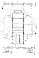
Figure 1 represents a ground plan view of the tray completely disassembled. -
Figure 2 shows a lateral view of the tray. -
Figure 3 illustrates a section offigure 1 by A-A'. -
Figure 4 corresponds to a close-up of one of the peripheral projections of the base of the tray, the slot where it fits and the weakening line. -
Figure 5 shows a close-up of the hole where the tabs fit for the folding of the tray. -
Figure 5 shows an underside view of the tray, were the smaller faces have been folded. -
Figure 7 illustrates an upper view of the tray with the small faces folded. -
Figure 8 corresponds to a section offigure 6 by B-B'. -
Figure 9 shows a close-up of one of the projects that the base of the tray has. -
Figure 10 shows one of the tabs that fit into the holes in the base of the tray. -
Figure 11 illustrates the tray completely assembled. -
Figures 12 and 13 show different close-ups where the fitting of the larger, smaller faces and base of the tray can be observed. - To show clearly the nature and scope of the advantageous application of the container tray for assembleable and stackable products, which constitutes the purpose of the claimed invention, its structure is described below, referring to the drawings that, by showing a preferred realisation of said object, with an informative character, they must be considered in their broadest sense and not as limitations of the application and the content of the claimed invention.
- The four faces (1, 2, 3 and 4) that make up the tray are related to the base or bottom by weakening lines (5) of the plastic material, so that in practice they act like hinges.
- The first phase for setting up the tray consists of vertically pressing the larger faces (1 and 2) on the base and then doing the same with the smaller faces (3 and 4).
- The fitting together of the larger faces (1 and 2) and the smaller ones (3 and 4) is achieved through the lateral box holes (6) that the larger faces (1 and 2) have on their straight edge (7) and the lateral box holes (8) that these larger faces (1 and 2) have on their other edge (9). The projections (10 and 11) that the smaller faces (3 and 4) have for this purpose fit into these box holes (6 and 8) by pressure.
- The base of the tray has projections (12) on its lateral edge that are introduced in the box holes (13) that the two larger faces (1 and 2) and the back face (3) of the tray have for this purpose; completing the assembly of the tray by introducing the projections (11) of the smaller face (4) in the box holes (8) that the coinciding side (9) of the larger faces has for this purpose.
- In practice, for its packaging, presentation and transport, the smaller faces (3 and 4) are folded underneath the base; being fastened thanks to one of the small faces having tabs (14) that fit into holes (15) in the bottom of the tray, with one smaller face (3), the back part of the tray, being supported by the other smaller face (4).
Claims (2)
- "Container tray for products that can be assembled and stacked", characterised by the four faces (1, 2, 3 and 4) that make up the tray being related to the base or bottom by weakening lines (5) of the plastic material, acting in practice like hinges, so that the shape of the tray when it is completely unfolded consists of the vertical pressing of the larger sides (1 and 2) and the smaller sides (3 and 4) onto the base, fitting them together by using the lateral box holes (6) of the larger faces (1 and 2) in its straight side (7) and lateral box holes (8) that these larger faces (1 and 2) have in their other side (9), fitting into them the tabs (10 and 11) that the smaller faces (3 and 4) have, and with the base of the tray having projections (12) on its lateral edge in which the box holes are introduced (13) which the two larger side faces (1 and 2) and the back face (3) of the tray have for this purpose; completing the assembly of the tray by introducing the projections (11) of the smaller face in box holes (8) that the coinciding side (9) of the larger faces have for this purpose.
- "Container tray for products that can be assembled and stacked", according to claim 1, characterised by the folding, for packing, presentation and transport, of the smaller sides (3 and 4) to the bottom but on the under side; being adhered thanks to one of its faces having tabs (14) that fit into the holes (15) of the base of the tray, with one smaller face (3), which makes up the back side of the tray, being supported by the other smaller face (4).
Priority Applications (1)
| Application Number | Priority Date | Filing Date | Title |
|---|---|---|---|
| EP08380190A EP2141076A1 (en) | 2008-07-02 | 2008-07-02 | Foldably collapsible plastic tray |
Applications Claiming Priority (1)
| Application Number | Priority Date | Filing Date | Title |
|---|---|---|---|
| EP08380190A EP2141076A1 (en) | 2008-07-02 | 2008-07-02 | Foldably collapsible plastic tray |
Publications (1)
| Publication Number | Publication Date |
|---|---|
| EP2141076A1 true EP2141076A1 (en) | 2010-01-06 |
Family
ID=39926523
Family Applications (1)
| Application Number | Title | Priority Date | Filing Date |
|---|---|---|---|
| EP08380190A Withdrawn EP2141076A1 (en) | 2008-07-02 | 2008-07-02 | Foldably collapsible plastic tray |
Country Status (1)
| Country | Link |
|---|---|
| EP (1) | EP2141076A1 (en) |
Citations (3)
| Publication number | Priority date | Publication date | Assignee | Title |
|---|---|---|---|---|
| EP0659650A1 (en) * | 1993-12-21 | 1995-06-28 | Proplast-A. Hatzopoylos-G. Antonaras O.E. | Folding box |
| DE9218977U1 (en) * | 1992-01-17 | 1996-08-08 | Schoeller-Plast S.A., Romont | Containers made of plastic, in particular vegetable containers, with foldable side walls |
| WO1999002410A1 (en) * | 1997-07-11 | 1999-01-21 | Vitaliano Raiola | A collapsible plastic box |
-
2008
- 2008-07-02 EP EP08380190A patent/EP2141076A1/en not_active Withdrawn
Patent Citations (3)
| Publication number | Priority date | Publication date | Assignee | Title |
|---|---|---|---|---|
| DE9218977U1 (en) * | 1992-01-17 | 1996-08-08 | Schoeller-Plast S.A., Romont | Containers made of plastic, in particular vegetable containers, with foldable side walls |
| EP0659650A1 (en) * | 1993-12-21 | 1995-06-28 | Proplast-A. Hatzopoylos-G. Antonaras O.E. | Folding box |
| WO1999002410A1 (en) * | 1997-07-11 | 1999-01-21 | Vitaliano Raiola | A collapsible plastic box |
Similar Documents
| Publication | Publication Date | Title |
|---|---|---|
| US20090314661A1 (en) | Convertible display carton | |
| US8602212B2 (en) | Stackable display container with box portion and reinforcing layer | |
| EP3184459B1 (en) | Shipping container convertible into a display configuration | |
| MX2014011303A (en) | Display tray. | |
| JP6423239B2 (en) | Assembly box | |
| US20040232039A1 (en) | Multi-purpose shipping and display container | |
| US20110147442A1 (en) | Package for food prodcuts | |
| US8033448B2 (en) | Tray insert movable between collapsed and erected positions | |
| CN103380059A (en) | Medical product package | |
| KR101705019B1 (en) | Packaging container | |
| US9205947B1 (en) | Multi-component container with air cell end panel reinforcements | |
| EP0940345A1 (en) | Carton with product dividers | |
| US6789726B2 (en) | Multi-purpose packing, shipping and display container | |
| JP2014156276A (en) | Packing box | |
| CA2876989C (en) | Packaging | |
| US20060144910A1 (en) | Container and container blank usable with a liquid impermeable bag | |
| US20150023614A1 (en) | Flexible Pouches for Goods on a Roll | |
| CN106660660A (en) | Package assembly comprising inner and outer containers, method of manufacturing thereof, methods of storing/displaying products therewith and blank for forming the outer container thereof | |
| US20160120345A1 (en) | Item of Food Packaging | |
| KR20070045931A (en) | Card file | |
| CN207536332U (en) | A kind of milk powder machine carton | |
| CZ28287U1 (en) | Sales package and sales wrapper | |
| GB2530339A (en) | Tilting Packaging | |
| JP2011042376A (en) | Packaging box | |
| EP1746034A1 (en) | Transport and display container |
Legal Events
| Date | Code | Title | Description |
|---|---|---|---|
| PUAI | Public reference made under article 153(3) epc to a published international application that has entered the european phase |
Free format text: ORIGINAL CODE: 0009012 |
|
| AK | Designated contracting states |
Kind code of ref document: A1 Designated state(s): AT BE BG CH CY CZ DE DK EE ES FI FR GB GR HR HU IE IS IT LI LT LU LV MC MT NL NO PL PT RO SE SI SK TR |
|
| AX | Request for extension of the european patent |
Extension state: AL BA MK RS |
|
| 17P | Request for examination filed |
Effective date: 20100705 |
|
| AKX | Designation fees paid |
Designated state(s): AT BE BG CH CY CZ DE DK EE ES FI FR GB GR HR HU IE IS IT LI LT LU LV MC MT NL NO PL PT RO SE SI SK TR |
|
| 17Q | First examination report despatched |
Effective date: 20100813 |
|
| STAA | Information on the status of an ep patent application or granted ep patent |
Free format text: STATUS: THE APPLICATION IS DEEMED TO BE WITHDRAWN |
|
| 18D | Application deemed to be withdrawn |
Effective date: 20111025 |