EP2140164B1 - Spacer element and braking device - Google Patents
Spacer element and braking device Download PDFInfo
- Publication number
- EP2140164B1 EP2140164B1 EP08734809A EP08734809A EP2140164B1 EP 2140164 B1 EP2140164 B1 EP 2140164B1 EP 08734809 A EP08734809 A EP 08734809A EP 08734809 A EP08734809 A EP 08734809A EP 2140164 B1 EP2140164 B1 EP 2140164B1
- Authority
- EP
- European Patent Office
- Prior art keywords
- brake
- braking device
- spacer element
- braking
- flange
- Prior art date
- Legal status (The legal status is an assumption and is not a legal conclusion. Google has not performed a legal analysis and makes no representation as to the accuracy of the status listed.)
- Not-in-force
Links
Images


Classifications
-
- F—MECHANICAL ENGINEERING; LIGHTING; HEATING; WEAPONS; BLASTING
- F16—ENGINEERING ELEMENTS AND UNITS; GENERAL MEASURES FOR PRODUCING AND MAINTAINING EFFECTIVE FUNCTIONING OF MACHINES OR INSTALLATIONS; THERMAL INSULATION IN GENERAL
- F16D—COUPLINGS FOR TRANSMITTING ROTATION; CLUTCHES; BRAKES
- F16D65/00—Parts or details
- F16D65/02—Braking members; Mounting thereof
- F16D65/12—Discs; Drums for disc brakes
- F16D65/122—Discs; Drums for disc brakes adapted for mounting of friction pads
-
- F—MECHANICAL ENGINEERING; LIGHTING; HEATING; WEAPONS; BLASTING
- F16—ENGINEERING ELEMENTS AND UNITS; GENERAL MEASURES FOR PRODUCING AND MAINTAINING EFFECTIVE FUNCTIONING OF MACHINES OR INSTALLATIONS; THERMAL INSULATION IN GENERAL
- F16D—COUPLINGS FOR TRANSMITTING ROTATION; CLUTCHES; BRAKES
- F16D65/00—Parts or details
- F16D65/38—Slack adjusters
- F16D65/40—Slack adjusters mechanical
- F16D65/42—Slack adjusters mechanical non-automatic
-
- F—MECHANICAL ENGINEERING; LIGHTING; HEATING; WEAPONS; BLASTING
- F16—ENGINEERING ELEMENTS AND UNITS; GENERAL MEASURES FOR PRODUCING AND MAINTAINING EFFECTIVE FUNCTIONING OF MACHINES OR INSTALLATIONS; THERMAL INSULATION IN GENERAL
- F16D—COUPLINGS FOR TRANSMITTING ROTATION; CLUTCHES; BRAKES
- F16D65/00—Parts or details
- F16D65/38—Slack adjusters
- F16D65/40—Slack adjusters mechanical
- F16D65/52—Slack adjusters mechanical self-acting in one direction for adjusting excessive play
- F16D65/54—Slack adjusters mechanical self-acting in one direction for adjusting excessive play by means of direct linear adjustment
-
- F—MECHANICAL ENGINEERING; LIGHTING; HEATING; WEAPONS; BLASTING
- F16—ENGINEERING ELEMENTS AND UNITS; GENERAL MEASURES FOR PRODUCING AND MAINTAINING EFFECTIVE FUNCTIONING OF MACHINES OR INSTALLATIONS; THERMAL INSULATION IN GENERAL
- F16D—COUPLINGS FOR TRANSMITTING ROTATION; CLUTCHES; BRAKES
- F16D69/00—Friction linings; Attachment thereof; Selection of coacting friction substances or surfaces
- F16D69/04—Attachment of linings
- F16D69/0408—Attachment of linings specially adapted for plane linings
-
- F—MECHANICAL ENGINEERING; LIGHTING; HEATING; WEAPONS; BLASTING
- F16—ENGINEERING ELEMENTS AND UNITS; GENERAL MEASURES FOR PRODUCING AND MAINTAINING EFFECTIVE FUNCTIONING OF MACHINES OR INSTALLATIONS; THERMAL INSULATION IN GENERAL
- F16D—COUPLINGS FOR TRANSMITTING ROTATION; CLUTCHES; BRAKES
- F16D55/00—Brakes with substantially-radial braking surfaces pressed together in axial direction, e.g. disc brakes
- F16D2055/0004—Parts or details of disc brakes
- F16D2055/0058—Fully lined, i.e. braking surface extending over the entire disc circumference
-
- F—MECHANICAL ENGINEERING; LIGHTING; HEATING; WEAPONS; BLASTING
- F16—ENGINEERING ELEMENTS AND UNITS; GENERAL MEASURES FOR PRODUCING AND MAINTAINING EFFECTIVE FUNCTIONING OF MACHINES OR INSTALLATIONS; THERMAL INSULATION IN GENERAL
- F16D—COUPLINGS FOR TRANSMITTING ROTATION; CLUTCHES; BRAKES
- F16D2121/00—Type of actuator operation force
- F16D2121/18—Electric or magnetic
- F16D2121/20—Electric or magnetic using electromagnets
- F16D2121/22—Electric or magnetic using electromagnets for releasing a normally applied brake
Definitions
- the invention relates to a braking device with a spacer element.
- Such safety brakes are often designed as so-called electromagnetic spring pressure brakes, in which the brake disk assembly is clamped under spring action between two brake flanges.
- the brake disk assembly is non-rotatably mounted on a shaft end, which is coupled for example with an electric motor or a transmission to be braked.
- brakes are for example from the EP-A-1 452 764 or the DE-U-85 19 223 known.
- the brake discs are covered with brake pads, which are mounted in a conventional manner on the radial surfaces of the brake disc (for example, by soldering, gluing or mechanical fasteners such as rivets or screws).
- brake pads are mounted in a conventional manner on the radial surfaces of the brake disc (for example, by soldering, gluing or mechanical fasteners such as rivets or screws).
- Such brake discs must be completely replaced when worn brake pads. This means that even if only the brake pads are worn and the actual brake disc is still completely intact, this component must be renewed.
- Brake disc assemblies with worn brake pads can indeed, be recycled by replacing the worn pads with new pads. However, this is expensive, since solder joints must be solved and reworked or difficult to detach fasteners (rivets) must be removed.
- Such a brake pad assembly is usually suitable only for a limited number of reprocessing cycles
- the brake disc assembly is as floating as possible between the brake flanges, i. must be arranged in the axial direction movable on the shaft end to be braked. Only in this way can it be ensured that a uniform braking effect can be achieved on both brake disk sides, especially in the case of heavily worn brake linings. So it is relatively accurate and expensive shaft-hub connections between the brake disc and the shaft end required, which allow such an axial displacement.
- stepped discs adjustments known to be distributed over the circumference of the brake elements (brake flanges, brake disc).
- the step discs have on their circumference different thickness edge portions which are clamped, for example, between magnet pot and the brake housing to determine the strength of the air gap.
- stepped discs must be individually released, adjusted and fixed. There is a risk of incorrect settings or the risk that different degrees border areas are set at different stages discs.
- a wear adjustment is known in which a threaded axially adjustable housing cover, which also serves as a brake pad carrier. Brake pad wear can be compensated by unscrewing the cover either on or off the housing. About locking screws, the lid is locked in a continuously selectable rotational position.
- the object of the present invention is to provide a brake disk assembly or a brake assembly in which the wear, the maintenance and the adjustment properties are at least partially improved.
- the braking device according to claim 1 with a spacer element or actuator, over which without disassembly of the braking device, the wear can be gradually compensated.
- the adjustable spacer which acts in a position between the brake flange and the stop, can reduce the air gap by a certain dimension D and thus compensate for a corresponding wear of the brake lining elements.
- the release or brake gap can be readjusted step by step and without extensive adjustments to wear.
- this measure increases the life or the service life of the brake lining elements, and the required maintenance intervals for replacement of the brake elements are extended. This in turn reduces the operating costs of a corresponding brake device.
- a single spacer acts with its edge regions between all stops and the corresponding brake flange.
- the braking device can be readjusted according to wear in a single operation.
- a fixing is provided which fixes the spacer element in its first and / or second position on the brake flange.
- the spacer element is to be adjusted in a direction of adjustment, which extends transversely to an axis extending in the brake force direction axis. That is to adjust the spacer is simply moved on the brake flange.
- the spacer element according to claim 5 as around the axis 14 - that is formed in the circumferential direction - adjustable rotary ring.
- the brake lining elements are arranged in the brake disc passing through openings. That is, the brake pads are no longer arranged on or on the surface of the radial surfaces of the brake disc, but protrude on both sides axially from corresponding openings in the brake disc out.
- the openings in this case comprise the brake lining elements wholly or partially, so that they are positively fixed radially and circumferentially to the brake disc.
- the end faces on the protruding from the brake disc surfaces ends of the brake pad elements act as braking surfaces on the corresponding mating surfaces of the brake flanges.
- the axial braking force generates a retarding frictional force in the circumferential direction at the interfaces, which is transmitted via the brake disc on the shaft end to be braked. If the brake lining elements wear out, it is not necessary to replace the entire brake disc, but it is sufficient to replace the worn brake lining elements with new brake lining elements.
- the brake lining elements are namely arranged "floating" and self-centering in the brake disc and are directed to the brake flanges acting on them, largely independent of the axial position of the brake disc itself.
- the brake disc can thus be fixed with relatively large axial tolerances on the shaft end to be braked ,
- the embodiment according to claim 8 allows a particularly good power transmission between the brake lining elements and the brake disc.
- the special embodiment according to claim 9 a manufacturing technology particularly favorable form.
- both the brake lining elements and the receiving openings in the brake disc can be made particularly easy and accurate tolerable.
- the kidney shape allows a large braking surface with comparatively few braking elements.
- Another advantage of the disclosed brake disc assemblies is that they can be installed in virtually any position, i. the axis can be horizontal, oblique or vertical. Nevertheless, it is ensured that the brake lining elements do not grind or only minimally on the brake flanges, even when the brake is released. This effect is achieved in that when releasing the brake, the brake disc is set back in rotation, while the brake lining elements arranged in the openings are pressed by the centrifugal force to the outside in the corresponding receiving openings. The occurring centrifugal force causes such a strong friction between brake disc openings and brake lining elements that they can no longer move under their own weight in the axial direction in the openings.
- the bremsflanschston tending forces in the circumferential direction via guide elements are transmitted non-positively to a body, which in turn can be supported on a fixed relative to the braked shaft end housing.
- the braking force itself is applied via a spring arrangement, which counteracts a magnetic force which is applied via a corresponding anchor ring arrangement.
- a spring arrangement between the two brake flanges is provided, which pushes them apart when the brake device is released and thus exposes the end faces of the brake lining elements regardless of the installation position of the braking device.
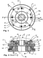
- the brake device 1 can be flanged to the housing of a drive unit via a base body 2 and fastening screws 4 (housing and drive unit are not shown).
- a shaft end protrudes from the drive unit through the base body 2 into the hub 8 of the brake disk 10, which is non-rotatably connected to the shaft end via a feather key connection 12.
- the brake disc is also fixed in the axial direction of the main axis 14 on the shaft end.
- the brake disk 10 lies with its flange region 16 between the brake flanges 18 and 20, which are arranged coaxially to the main body 2.
- the brake flanges 18 and 20 sit axially displaceable on stud bolts 22 which are fixed by threads in the base body 2.
- the axial movement range of the brake flanges 18 and 20 is fixed on the one hand by the transmission-facing end face of the main body 2 and the end faces of the stop nuts 24 facing the transmission.
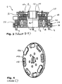
- brake springs 26 are provided, which are supported between the pressure plate 28 and the brake flange 18.
- the position of the brake springs 26 is defined by corresponding recesses (not shown) in the pressure plate 28 and in the brake flange 18.
- the axial position of the pressure plate 28 is adjustable via an adjusting nut 30 which is coupled via a thread to the base body 2.
- suitable fixing elements for example screws
- the braking force is via the axial adjustment the adjusting nut 30 and thus the pressure plate 28 adjustable by the bias of the brake springs is changed accordingly.
- a plurality of through holes 32 are provided in the cylindrical brake lining elements 34 are used.
- the end faces of the brake lining elements run between the mutually facing radial surfaces 19 and 21 of the brake flanges 18 and 20. These radial surfaces 19 and 21 together with the end faces the friction pairings, which lead to the braking effect.
- the brake lining elements 34 can move axially in the through bores 32, so that no axial forces are transmitted to the flange region 16 of the brake disk 10.
- the brake pad elements 34 are clamped between the brake flanges 18 and 20 and thus put over their peripheral surfaces which are positively coupled to the through holes 32 of the flange portion 16 of the brake disc 10, the brake disc 10 and thus via the hub 8 and the feather key 12 to be braked shaft end firmly.
- the occurring circumferential forces on the brake flanges 18 and 20 are via anti-rotation 36 ( Fig. 3 ), with are screwed to the base body 2, transmitted to the base body 2 and the fastening screws 4 on the transmission housing.
- the studs 22 and the corresponding through holes in the brake flanges 18 and 20 are dimensioned so that no circumferential forces are transmitted here. That is, the studs 22 transmit only the actual braking force in the axial direction, while the resulting braking torque is transmitted via the anti-rotation 36.
- an electrically energizable armature coil 38 is provided in the base body 2, which magnetizes the base body 2 upon application of a corresponding voltage such that it attracts the brake flange 18 by overcoming the braking force and removes the frictional action between the radial surfaces 19 and 21 and the brake lining elements ,
- the stud bolts 22 surrounding coil springs 40 are provided between the brake flanges 18 and 20, which presses the brake flange 20 against the stop nuts 24 when dissolved (released brake).
- the brake flange 20 thus assumes regardless of the operating state (braked, loosened) and of the installation position of the brake device 1 always a defined axial position on the stop nuts 24 a.
- the brake disk 10 When the brake is released, the brake disk 10 is rotated again via the driven shaft end. As a result, the brake pad elements 34 are pressed by the centrifugal forces occurring outwardly into the through holes 32. The friction thus constructed prevents axial movement of the brake pad members 34 in the through holes 32. That is, the brake device 1 can be installed in any position without the braking or wear properties by different positions of the Brake lining elements 34 to the brake flanges 18 and 20 and the radial surfaces 19 and 21 would change.
- the brake lining elements 34 wear. That is, the original distance B between the end faces decreases with time to the distance b. Thus, the original brake gap s is greater and grows to the amount S (see Fig. 5 ). By this effect, the braking distance is extended and the brake springs 26 must continue to expand to overcome the brake gap S. This reduces the braking force and increases the brake application time. Both effects are undesirable.
- an adjustable spacer ring 42 is arranged on the outer surface of the brake flange 21, which is fastened fittingly via fastening screws 44 on the brake flange.
- keyhole-like recesses 46 are provided which surround the stop nuts 24 in its initial position (with new brake lining elements 34) with its wide portion 46 a. In this position, the brake flange 20 is supported with its outer radial surface in the region of the studs 22 directly on the stop nut 24.
- the spacer ring 42 can be achieved via the fastening elements 44 when the drive shaft is stationary and the brake is released. Subsequently, the brake flange 20 is pressed together with the spacer ring 42 overcoming the force applied by the coil springs 40 spreading force inside. In this case, also the brake lining elements 34 move axially in the through holes 32 and reduce the air gap to the brake flange 18. With appropriate wear is an axial displacement so far as possible that the spacer ring 42 with its outer radial surface completely so far "passes under" the stop nuts 24 that the spacer ring 42 is rotatable in the circumferential direction, so that its narrow portion 46 b can be moved under the stop nuts 24.
- the spacer ring 42 is rotatable in the circumferential direction.
- a spacer element (not shown) can be provided, which is formed transversely to the axis of rotation 14 slidably. Such a design may be easier to adjust in operation.
- brake disk 110 shows an alternative embodiment of the brake lining elements 134, which are not cylindrical here but prismatic, kidney-shaped and sit in corresponding through holes 106.
- the effective friction surface can be increased.
- other cross-sectional shapes of the brake lining elements can be realized.
- the in the 6 and 7 shown embodiment relates to a brake device 1 ', in which brake pads 34' are arranged on the brake flanges 18 'and 20', which act on an uncoated brake disc 10 '.
- This embodiment also shows an alternative coupling of the brake disc 10 'via a Dahlkant with the shaft end.
- the brake disc 10 'itself must be arranged axially displaceable on the shaft end to prevent constraining forces during braking.
- the wear compensation takes place here analogously via a corresponding spacer ring 42 ', ie, the compensation mechanism is suitable for braking devices 1', which have no axially displaceable brake lining elements 34, 134.
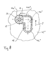
- Fig. 8 shows one of several adjustment of a spacer 42 "with a rectangular opening 46".
- a multi-stage readjustment can also be realized with a spacer element 42 "which can be linearly adjusted transversely to the axis of rotation.
- the recess 46 is formed as an angular guide slot of the stud bolt 22, so that a displacement in two different directions (transverse In this case, a first compensation can take place in a first displacement direction Z and a second compensation can take place in a second displacement direction Y (perpendicular to the first) .
- This embodiment allows a two-stage defined adjustment in which the respective adjustment process is in each case by a defined displacement.
- the adjustment is made one after the other from position 1 ( Fig. 8 ) in the position 2 against the stop of the transverse portion of the recess 42 "and then in position 3 against the end of this recess.
- the stud bolt 22 and the stop nut 24 are arranged in the region of the recess 46a "in position 1. In this position, the spacer element 42" does not act between the stop nuts 24 and the flange 18. Rather, the flange 18 itself bears against the stop nut.
- the spacer element 42 In position 2, the spacer element 42 "is displaced towards the stud bolts 22 and the stop nuts 24 in the direction Z, that the region 46b" below the stop nut 24 is arranged or, in other words, between the flange 18 and the surface facing the Stop nut 24 is located.
- the region 46b has a thickness D by which the air gap is reduced in this position.
- the spacer 42 " is displaced from the position 2 in the direction Y to the position 3.
- the region 46c" passes under the stop nut 24.
- the region 46c " has a thickness D 'which is greater as the thickness D in the region 46b ".
- the spacer ring 42, 42 'in the region of the openings 46, 46' may also be stepped, so that the Lsymmetrical spaltnachwolf can be done in several steps. It can also spacer rings 42, 42 'are used with different thicknesses D, which may also be used in combination.
Landscapes
- Engineering & Computer Science (AREA)
- General Engineering & Computer Science (AREA)
- Mechanical Engineering (AREA)
- Braking Arrangements (AREA)
- Valve Device For Special Equipments (AREA)
Abstract
Description
Die Erfindung betrifft eine Bremsvorrichtung mit einem Distanzelement.The invention relates to a braking device with a spacer element.
Bekannte Bremsvorrichtungen dienen auch als Sicherheitsbremsen. Solche Sicherheitsbremsen sind oft als sogenannte elektromagnetische Federdruckbremsen ausgebildet, bei denen die Bremsscheibenanordnung unter Federwirkung zwischen zwei Bremsflanschen eingeklemmt wird. Die Bremsscheibenanordnung sitzt dabei drehfest auf einem Wellenende, das beispielsweise mit einem abzubremsenden Elektromotor oder einem Getriebe gekoppelt ist.Known brake devices also serve as safety brakes. Such safety brakes are often designed as so-called electromagnetic spring pressure brakes, in which the brake disk assembly is clamped under spring action between two brake flanges. The brake disk assembly is non-rotatably mounted on a shaft end, which is coupled for example with an electric motor or a transmission to be braked.
Zum Lösen (Lüften) der Bremse wird die Bremswirkung meist elektromagnetisch aufgehoben und die Bremsscheibenanordnung freigestellt. Solche Bremsen sind beispielsweise aus der
Ein weiteres Problem besteht darin, dass die Bremsscheibenanordnung möglichst schwimmend zwischen den Bremsflanschen, d.h. in axialer Richtung beweglich auf dem abzubremsenden Wellenende angeordnet sein muss. Nur so kann sichergestellt werden, dass insbesondere bei stärker abgenutzten Bremsbelägen auf beiden Bremsscheibenseiten eine gleichmäßige Bremswirkung erzielt werden kann. Es sind also relativ genaue und aufwendige Welle-Nabe-Verbindungen zwischen Bremsscheibe und dem Wellenende erforderlich, die so eine Axialverschiebung zulassen.Another problem is that the brake disc assembly is as floating as possible between the brake flanges, i. must be arranged in the axial direction movable on the shaft end to be braked. Only in this way can it be ensured that a uniform braking effect can be achieved on both brake disk sides, especially in the case of heavily worn brake linings. So it is relatively accurate and expensive shaft-hub connections between the brake disc and the shaft end required, which allow such an axial displacement.
Aus der
Durch den Verschleiß der aktiven Bremsflächen an den Bremsflanschen und insbesondere der Bremsbeläge selbst verändert sich mit zunehmender Betriebsdauer der beim Bremsen zu überwindende Lüftspalt; er wird größer. Damit erhöht sich die Einfallzeit einer solchen Bremse und die Bremswirkung verzögert sich mit zunehmendem Verschleiß. Um dies auszugleichen, können verstellbare Anschläge vorgesehen werden, die den Lüftspalt festlegen. Bei ringförmigen Bremselementen müssen jedoch in der Regel mehrere solcher Anschläge in sehr genau definierter Weise verstellt werden, um über den gesamten Wirkbereich (in Umfangsrichtung) der Bremselemente konstante Bremseigenschaften und damit einen konstanten Verschleiß zu gewährleisten. Die Einzelverstellung der Anschläge ist meist vor Ort - also bei montierter Bremse - nicht oder nur sehr schwer möglich.Due to the wear of the active braking surfaces on the brake flanges and in particular the brake pads themselves changes with increasing operating time of the brake gap to be overcome; he is getting bigger. This increases the incidence of such a brake and the braking effect is delayed with increasing wear. To compensate for this, adjustable stops can be provided which define the air gap. In the case of annular brake elements, however, as a rule several such stops must be adjusted in a very precisely defined manner so as to be able to pass over the whole Effective range (in the circumferential direction) of the brake elements constant braking properties and thus to ensure a constant wear. The individual adjustment of the attacks is usually on site - ie with mounted brake - not possible or only with great difficulty.
Um das Nachstellen zu vereinfachen, sind z.B. aus der
Aus der
Davon ausgehend besteht die Aufgabe der vorliegenden Erfindung darin, eine Bremsscheibenanordnung bzw. eine Bremsanordnung bereitzustellen, bei der die Verschleiß-, die Wartungs- und die Justiereigenschaften wenigstens teilweise verbessert sind.Based on this, the object of the present invention is to provide a brake disk assembly or a brake assembly in which the wear, the maintenance and the adjustment properties are at least partially improved.
Diese Aufgabe löst die Bremsvorrichtung gemäß Anspruch 1 mit einem Distanzelement oder Stellelement, über das ohne Demontage der Bremsvorrichtung der Verschleiß stufenweise ausgeglichen werden kann. Das verstellbare Distanzelement, das in einer Stellung zwischen Bremsflansch und dem Anschlag wirkt, kann den Lüftspalt um eine bestimmte Dimension D verringern und so einen entsprechenden Verschleiß der Bremsbelagelemente ausgleichen. Damit kann der Lüft- bzw. Bremsspalt stufenweise und ohne aufwendige Einstellarbeiten dem Verschleiß entsprechend nachjustiert werden. Gleichzeitig erhöht diese Maßnahme die Lebensdauer bzw. die Betriebsdauer der Bremsbelagelemente, und die erforderlichen Wartungsintervalle zum Austausch der Bremselemente werden verlängert. Dies wiederum senkt die Betriebskosten einer entsprechenden Bremsvorrichtung.This object is achieved by the braking device according to
Gemäß Anspruch 2 wirkt ein einziges Distanzelement mit seinen Randbereichen zwischen allen Anschlägen und dem entsprechenden Bremsflansch. Die Bremsvorrichtung kann in einem einzigen Arbeitsgang dem Verschleiß entsprechend nachgestellt werden.According to
Gemäß Anspruch 3 ist eine Fixierung vorgesehen, die das Distanzelement in seiner ersten und/oder zweiten Stellung am Bremsflansch fixiert.According to claim 3, a fixing is provided which fixes the spacer element in its first and / or second position on the brake flange.
Gemäß Anspruch 4 ist das Distanzelement in einer Stellrichtung zu verstellen, die quer zu einer in Bremskraftrichtung verlaufenden Achse verläuft. Das heißt zum Verstellen wird das Distanzelement einfach auf dem Bremsflansch verschoben. Dabei ist das Distanzelement gemäß Anspruch 5 als um die Achse 14 - also in Umfangsrichtung - verstellbarer Drehring ausgebildet.In accordance with
Nach Anspruch 6 sind die Bremsbelagelemente in die Bremsscheibe durchsetzenden Öffnungen angeordnet sind. Das heißt, die Bremsbeläge sind nicht mehr auf bzw. an der Oberfläche der Radialflächen der Bremsscheibe angeordnet, sondern ragen jeweils beidseitig axial aus entsprechenden Öffnungen in der Bremsscheibe heraus. Die Öffnungen umfassen dabei die Bremsbelagelemente ganz oder teilweise, so dass diese formschlüssig radial und in Umfangsrichtung zur Bremsscheibe fixiert sind. Die Stirnflächen an den aus den Bremsscheibenoberflächen herausragenden Enden der Bremsbelagelemente wirken als Bremsflächen an den entsprechenden Gegenflächen der Bremsflansche. Die axiale Bremskraft erzeugt eine verzögernde Reibkraft in Umfangsrichtung an den Grenzflächen, die über die Bremsscheibe auf das abzubremsende Wellenende übertragen wird. Bei Verschleiß der Bremsbelagelemente muss nicht die gesamte Bremsscheibe ausgetauscht werden, sondern es genügt, die verschlissenen Bremsbelagelemente gegen neue Bremsbelagelemente zu ersetzen.According to
Dabei erlaubt die Ausführung gemäß Anspruch 7, bei der die Bremsbelagelemente in Richtung der Bremskraft verschieblich angeordnet sind, eine montagetechnisch besonders günstige Ausführung. Die Bremsbelagelemente sind nämlich "schwimmend" und selbstzentrierend in der Bremsscheibe angeordnet und richten sich an den auf sie einwirkenden Bremsflanschen aus, und zwar weitgehend unabhängig von der axialen Lage der Bremsscheibe selbst. Die Bremsscheibe kann also mit relativ großen axialen Toleranzen am abzubremsenden Wellenende fixiert werden.In this case, the embodiment according to claim 7, wherein the brake lining elements are arranged displaceably in the direction of the braking force, a mounting technology particularly favorable design. The brake lining elements are namely arranged "floating" and self-centering in the brake disc and are directed to the brake flanges acting on them, largely independent of the axial position of the brake disc itself. The brake disc can thus be fixed with relatively large axial tolerances on the shaft end to be braked ,
Die Ausführung gemäß Anspruch 8 erlaubt eine besonders gute Kraftübertragung zwischen Bremsbelagelementen und Bremsscheibe. Und die spezielle Ausführung gemäß Anspruch 9 eine fertigungstechnisch besonders günstige Form. Dabei können sowohl die Bremsbelagelemente als auch die aufnehmenden Öffnungen in der Bremsscheibe besonders einfach und genau tolerierbar ausgeführt werden. Gleichzeitig ermöglicht die Nierenform eine große Bremswirkfläche mit vergleichsweise wenigen Bremselementen.The embodiment according to
Ein weiterer Vorteil der angegebenen Bremsscheibenanordnungen besteht darin, dass sie praktisch in jeder Lage eingebaut werden können, d.h. die Achse kann waagerecht, schräg oder senkrecht verlaufen. Es ist trotzdem sichergestellt, dass sich die Bremsbelagelemente auch bei gelöster Bremse nicht oder nur minimal an den Bremsflanschen schleifen. Dieser Effekt wird dadurch erzielt, dass beim Lösen der Bremse die Bremsscheibe wieder in Rotation versetzt wird, dabei werden die in den Öffnungen angeordneten Bremsbelagelemente durch die Zentrifugalkraft nach außen in die entsprechenden Aufnahmeöffnungen gedrückt. Die auftretende Zentrifugalkraft bewirkt eine so starke Reibkopplung zwischen Bremsscheibenöffnungen und Bremsbelagelementen, dass sich diese unter ihrem Eigengewicht nicht mehr in axialer Richtung in den Öffnungen verschieben können. Damit ist sichergestellt, dass die Bremsbelagelemente bei ungebremstem Betrieb, also bei gelüfteter Bremse, an den Bremsflanschen anliegen. Dieser Effekt ist durch eine verschieblich auf einem Wellenende angeordnete Bremsscheibe und an der Bremsscheibe bzw. den Bremsflanschen fixierten Bremsbelägen nicht erzielbar, da hier zwischen der Bremsscheibennabe und der angetriebenen Welle keine stabilisierenden Zentrifugalkräfte wirken.Another advantage of the disclosed brake disc assemblies is that they can be installed in virtually any position, i. the axis can be horizontal, oblique or vertical. Nevertheless, it is ensured that the brake lining elements do not grind or only minimally on the brake flanges, even when the brake is released. This effect is achieved in that when releasing the brake, the brake disc is set back in rotation, while the brake lining elements arranged in the openings are pressed by the centrifugal force to the outside in the corresponding receiving openings. The occurring centrifugal force causes such a strong friction between brake disc openings and brake lining elements that they can no longer move under their own weight in the axial direction in the openings. This ensures that the brake lining elements rest on the brake flanges during unrestrained operation, ie when the brake is released. This effect can not be achieved by a brake disk arranged displaceably on a shaft end and brake linings fixed to the brake disk or the brake flanges, since no stabilizing centrifugal forces act here between the brake disk hub and the driven shaft.
Bei weiteren Ausführungen werden die bremsflanschseitig wirkenden Kräfte in Umfangsrichtung über Führungselemente kraftschlüssig auf einen Grundkörper übertragen, welcher sich wiederum an einem gegenüber dem abzubremsenden Wellenende fixierten Gehäuse abstützen kann. Die Bremskraft selbst wird über eine Federanordnung aufgebracht, der eine Magnetkraft entgegenwirkt, die über eine entsprechende Ankerringanordnung aufgebracht wird.In further embodiments, the bremsflanschseitig acting forces in the circumferential direction via guide elements are transmitted non-positively to a body, which in turn can be supported on a fixed relative to the braked shaft end housing. The braking force itself is applied via a spring arrangement, which counteracts a magnetic force which is applied via a corresponding anchor ring arrangement.
Zusätzlich kann eine Federanordnung zwischen den beiden Bremsflanschen vorgesehen, die diese bei gelüfteter Bremsvorrichtung auseinanderdrückt und somit die Stirnflächen der Bremsbelagelemente unabhängig von der Einbaulage der Bremsvorrichtung freilegt.In addition, a spring arrangement between the two brake flanges is provided, which pushes them apart when the brake device is released and thus exposes the end faces of the brake lining elements regardless of the installation position of the braking device.
Ein Ausführungsbeispiel der vorliegenden Erfindung wird nun anhand der Zeichnungen beschrieben. Dabei zeigen:
- Fig. 1
- eine Vorderansicht einer erfindungsgemä- ßen Bremsvorrichtung,
- Fig. 2
- den Schnitt A-A aus
Fig. 1 , - Fig. 3
- den Schnitts B-B aus
Fig. 1 , - Fig. 4
- eine perspektivische Ansicht einer Brems- scheibe mit Bremskörpern,
- Fig. 5
- eine vergrößerte Darstellung des Bereichs C aus
Fig. 2 , - Fig. 6
- eine alternative Bremsvorrichtung,
- Fig. 7
- den Schnitts D-D aus
Fig. 6 und - Fig. 8
- einen alternativen Verstellbereich.
- Fig. 1
- a front view of a brake device according to the invention,
- Fig. 2
- the cut AA
Fig. 1 . - Fig. 3
- the cut BB off
Fig. 1 . - Fig. 4
- a perspective view of a brake disc with brake bodies,
- Fig. 5
- an enlarged view of the area C from
Fig. 2 . - Fig. 6
- an alternative braking device,
- Fig. 7
- the cut DD off
Fig. 6 and - Fig. 8
- an alternative adjustment range.
Aufbau und Funktion einer erfindungsgemäßen Bremsvorrichtung sind in den
Die Bremsflansche 18 und 20 sitzen axial verschieblich auf Stehbolzen 22, die über Gewinde im Grundkörper 2 fixiert sind. Der axiale Bewegungsbereich der Bremsflansche 18 und 20 wird zum einen durch die Getriebe-abgewandte Stirnseite des Grundkörpers 2 und die dem Getriebe zugewandten Stirnflächen der Anschlagmuttern 24 festgelegt.The brake flanges 18 and 20 sit axially displaceable on
Zum Aufbringen der Bremskraft sind Bremsfedern 26 vorgesehen, die sich zwischen der Druckplatte 28 und dem Bremsflansch 18 abstutzen. Die Lage der Bremsfedern 26 ist durch entsprechende Ausnehmungen (nicht dargestellt) in der Druckplatte 28 bzw. im Bremsflansch 18 vorgegeben. Die axiale Lage der Druckplatte 28 ist über eine Verstellmutter 30, die über ein Gewinde mit dem Grundkörper 2 gekoppelt ist, verstellbar. Zur Sicherung der axialen Verstelllage der Verstellmutter 30 können geeignete Fixierelemente (zum Beispiel Schrauben) vorgesehen sein. Die Bremskraft ist über die axiale Verstellung der Verstellmutter 30 und damit der Druckplatte 28 einstellbar, indem die Vorspannung der Bremsfedern entsprechend verändert wird.To apply the braking force brake springs 26 are provided, which are supported between the
Im Flanschbereich 16 sind mehrere Durchgangsbohrungen 32 vorgesehen, in die zylindrische Bremsbelagelemente 34 eingesetzt sind. Die Stirnflächen der Bremsbelagelemente verlaufen dabei zwischen den einander zugewandten Radialflächen 19 und 21 der Bremsflansche 18 und 20. Diese Radialflächen 19 und 21 bilden zusammen mit den Stirnflächen die Reibpaarungen, die zur Bremswirkung führen.In the flange portion 16 a plurality of through
Beim Bremsen drücken die Bremsfedern 26 den Flansch 18 axial mit seiner Radialfläche 19 gegen die entsprechenden Stirnflächen der Bremsbelagelemente 34. Diese wiederum übertragen die Bremskraft über ihre gegenüberliegenden Stirnflächen auf die Stirnfläche 21 des Bremsflansches 20, der sich an den Stirnflächen der Anschlagmuttern 24 abstützt, die wiederum die Bremskraft über eine Zugbeanspruchung der Stehbolzen 22 auf den Grundkörper 2 überträgt.When braking the brake springs 26 press the
Beim Bremsen können sich die Bremsbelagelemente 34 in den Durchgangsbohrungen 32 axial verschieben, so dass keine Axialkräfte auf den Flanschbereich 16 der Bremsscheibe 10 übertragen werden. Die Bremsbelagelemente 34 sind so zwischen den Bremsflanschen 18 und 20 eingeklemmt und legen damit über ihre Umfangsflächen, die formschlüssig mit den Durchgangsbohrungen 32 des Flanschbereichs 16 der Bremsscheibe 10 gekoppelt sind, die Bremsscheibe 10 und damit über die Nabe 8 und die Passfederverbindung 12 das abzubremsende Wellenende fest.During braking, the
Die dabei auftretenden Umfangskräfte an den Bremsflanschen 18 und 20 werden über Verdrehsicherungen 36 (
Zum Lüften der Bremse ist im Grundkörper 2 eine elektrisch erregbare Ankerspule 38 vorgesehen, die beim Anlegen einer entsprechenden Spannung den Grundkörper 2 so magnetisiert, dass dieser den Bremsflansch 18 unter Überwindung der Bremskraft anzieht und die Reibwirkung zwischen den Radialflächen 19 und 21 und den Bremsbelagelementen aufhebt. Dabei sind zwischen den Bremsflanschen 18 und 20 die Stehbolzen 22 umgebende Schraubenfedern 40 vorgesehen, die bei gelöster (gelüfteter Bremse) den Bremsflansch 20 gegen die Anschlagmuttern 24 drückt. Der Bremsflansch 20 nimmt damit unabhängig vom Betriebszustand (gebremst, gelöst) und von der Einbaulage der Bremsvorrichtung 1 immer eine definierte axiale Lage an den Anschlagmuttern 24 ein.To release the brake, an electrically
Bei gelöster Bremse wird die Bremsscheibe 10 über das angetriebene Wellenende wieder in Rotation versetzt. Dadurch werden die Bremsbelagelemente 34 durch die auftretenden Zentrifugalkräfte nach außen in die Durchgangsbohrungen 32 gedrückt. Der so aufgebaute Reibschluss verhindert eine Axialbewegung der Bremsbelagelemente 34 in den Durchgangsbohrungen 32. Das heißt, die Bremsvorrichtung 1 kann in jeder beliebigen Lage eingebaut werden, ohne dass sich die Brems- bzw. Verschleißeigenschaften durch unterschiedliche Stellungen der Bremsbelagelemente 34 zu den Bremsflanschen 18 und 20 bzw. deren Radialflächen 19 und 21 verändern würde.When the brake is released, the
Mit zunehmender Betriebsdauer der Bremsvorrichtung nutzen sich die Bremsbelagelemente 34 ab. Das heißt, der ursprüngliche Abstand B zwischen den Stirnflächen verringert sich mit der Zeit auf den Abstand b. Damit wird der ursprüngliche Bremsspalt s größer und wächst auf den Betrag S (siehe
Zum Ausgleich ist an der Außenfläche des Bremsflansches 21 ein verstellbarer Distanzring 42 angeordnet, der über Befestigungsschrauben 44 am Bremsflansch anliegend befestigt ist. Im Distanzring 42 sind schlüssellochartig ausgebildete Ausnehmungen 46 vorgesehen, die in ihrer Ausgangslage (bei neuen Bremsbelagelementen 34) mit ihrem weiten Abschnitt 46a die Anschlagmuttern 24 umgeben. In dieser Stellung stützt sich der Bremsflansch 20 mit seiner außenliegenden Radialfläche im Bereich der Stehbolzen 22 direkt an der Anschlagmutter 24 ab.For compensation, an
Bei zunehmendem Verschleiß der Bremsbelagelemente 34 kann bei stillstehender Antriebswelle und gelüfteter Bremse der Distanzring 42 über die Befestigungselemente 44 gelöst werden. Anschließend wird der Bremsflansch 20 zusammen mit dem Distanzring 42 unter Überwindung der durch die Schraubenfedern 40 aufgebrachten Spreizkraft nach innen gedrückt. Dabei verschieben sich ebenfalls die Bremsbelagelemente 34 axial in den Durchgangsbohrungen 32 und verringern den Lüftspalt zum Bremsflansch 18. Bei entsprechender Abnutzung ist eine Axialverschiebung so weit möglich, dass der Distanzring 42 mit seiner außenliegenden Radialfläche vollständig so weit "unter" die Anschlagmuttern 24 gelangt, dass der Distanzring 42 in Umfangsrichtung verdrehbar ist, so dass sein enger Abschnitt 46b unter die Anschlagmuttern 24 verschoben werden kann. In dieser Stellung werden die Befestigungselemente 44 wieder fixiert und der Distanzring ist wieder am Bremsflansch 20 befestigt. In dieser Stellung befindet sich der Distanzring 42 zwischen Anschlagmuttern 24 und Bremsflansch 20 und der Lüftspalt ist um die Dimension D (die Dicke des Distanzrings 42) verringert. Diese Nachstellmöglichkeit erlaubt eine schrittweise Kompensation der Abnutzung der Bremsbelagelemente 34, ohne dass dazu die Vorspannung der Bremsfedern 26 nachgestellt oder verändert werden müsste und ohne dass die Anschlagmuttern 24 verstellt werden müssten.With increasing wear of the
Im dargestellten Ausführungsbeispiel ist der Distanzring 42 in Umfangsrichtung verdrehbar ausgebildet. In anderen Ausführungen kann auch anstatt des Distanzrings 42 ein Distanzelement (nicht dargestellt) vorgesehen werden, das quer zur Rotationsachse 14 verschiebbar ausgebildet ist. So eine Ausführung ist unter Umständen im Betrieb leichter verstellbar.In the illustrated embodiment, the
Die in
Die in den
Die Nachstellung erfolgt nacheinander aus der Stellung 1 (
In der Stellung 2 ist das Distanzelement 42" so zu den Stehbolzen 22 und den Anschlagmuttern 24 in Richtung Z verschoben, dass der Bereich 46b" unter der Anschlagmutter 24 angeordnet ist oder, in anderen Worten, zwischen dem Flansch 18 und der diesem zugewandten Fläche der Anschlagmutter 24 liegt. Der Bereich 46b" weist eine Stärke D auf, um die der Lüftspalt in dieser Stellung verringert ist.In
Um eine weitere Nachstellung zu realisieren, wird das Distanzstück 42" aus der Stellung 2 in Richtung Y in die Stellung 3 verschoben. Dabei gelangt der Bereich 46c" unter die Anschlagmutter 24. Der Bereich 46c" weist eine Dicke D' auf, die größer ist als die Dicke D im Bereich 46b". Durch den zweiten Nachstellvorgang kann ein weiterer Verschleiß ausgeglichen werden und der Lüftspalt kann entsprechend nachgestellt werden. Der in
In anderen Ausführungen kann auch der Distanzring 42, 42' im Bereich der Öffnungen 46, 46' auch gestuft ausgebildet sein, so dass die Lüftspaltnachstellung in mehreren Schritten erfolgen kann. Es können auch Distanzringe 42, 42' mit unterschiedlichen Stärken D verwendet werden, die ggf. auch kombiniert einsetzbar sind.In other embodiments, the
Weitere Ausführungen und Varianten der vorliegenden Erfindung ergeben sich im Rahmen der anhängenden Ansprüche.Further embodiments and variants of the present invention will become apparent within the scope of the appended claims.
Claims (9)
- A braking device (1, 1') with a brake-disc arrangement in which brake-pad elements (34; 134; 34') are arranged between a first and a second brake flange (18, 20; 18', 20') and an air gap (S) is capable of being set by way of a plurality of stops (22, 24), and a spacer element (42; 42'; 42") which is adjustable transversely to the direction of the braking force and is capable of being set so as to act in the direction of the air gap, characterized in that the spacer element (42; 42'; 42") is designed in such a way that it is adjustable between a first position not acting upon the stop (22, 24; 22', 24') and a second position acting between the stop (22, 24; 22', 24') and the brake flange (18, 20; 18', 20') in the direction of the braking force and in the direction of the air gap respectively, so that in its second position the air gap (S) is reduced by a dimension (D; D') of the spacer element, and a corresponding wear of a brake-pad element (34; 134; 34') is capable of being compensated in this way.
- A braking device (1, 1') according to claim 1, in which the spacer element (42; 42'; 42") is constructed in one piece and has one recess (46; 46'; 46") in each case in the region of the stops (22, 24), wherein the recesses (46; 46'; 46") in the first position surround the stops (22, 24) with a region (46a; 46a'; 46a") and in the second position an edge region (46b; 46b'; 46b"; 46c") of the recess (46; 46'; 46") with the thickness (D; D') is arranged axially between the stop (22, 24) and the brake flange (18, 20; 18', 20').
- A braking device (1, 1') according to claim 1 or 2, in which the spacer element (42; 42'; 42") is arranged and designed in such a way that in its first and/or second position it is capable of being coupled to the brake flange (18, 20; 18', 20') by way of a fastening element (44) for fixing purposes.
- A braking device (1, 1') according to claim 1, 2 or 3, in which the spacer element (42; 42'; 42") is designed to be adjustable in a setting direction (Y, Z) transversely to an axis (14) extending in the direction of the braking force.
- A braking device (1, 1') according to claim 4, in which the spacer element (42; 42'; 42") is designed in the form of a turning ring (42; 42') adjustable about the axis (14).
- A braking device (1, 1') according to any one of claims 1 to 5, which has a brake disc (10, 110) with a plurality of brake-pad elements (34; 134) which are arranged in openings (32; 132) passing through the brake disc (10, 110).
- A braking device (1, 1') according to claim 6, in which the brake-pad elements (34; 134) are arranged so as to be displaceable in the direction of a braking force.
- A braking device (1, 1') according to any one of claims 6 or 7, in which the brake-pad elements (34; 134) and the openings (32; 132) have a mutually corresponding prismatic shape.
- A braking device (1, 1') according to claim 8, in which the brake-pad elements (34) are made kidney-shaped.
Applications Claiming Priority (2)
| Application Number | Priority Date | Filing Date | Title |
|---|---|---|---|
| DE102007014654A DE102007014654A1 (en) | 2007-03-27 | 2007-03-27 | Brake disc arrangement |
| PCT/EP2008/002422 WO2008116651A1 (en) | 2007-03-27 | 2008-03-27 | Spacer element and braking device |
Publications (2)
| Publication Number | Publication Date |
|---|---|
| EP2140164A1 EP2140164A1 (en) | 2010-01-06 |
| EP2140164B1 true EP2140164B1 (en) | 2010-08-18 |
Family
ID=39493327
Family Applications (1)
| Application Number | Title | Priority Date | Filing Date |
|---|---|---|---|
| EP08734809A Not-in-force EP2140164B1 (en) | 2007-03-27 | 2008-03-27 | Spacer element and braking device |
Country Status (4)
| Country | Link |
|---|---|
| EP (1) | EP2140164B1 (en) |
| AT (1) | ATE478273T1 (en) |
| DE (2) | DE102007014654A1 (en) |
| WO (1) | WO2008116651A1 (en) |
Families Citing this family (3)
| Publication number | Priority date | Publication date | Assignee | Title |
|---|---|---|---|---|
| IT1391331B1 (en) * | 2008-10-03 | 2011-12-05 | Rossi Motoriduttori S P A | SPRING ELECTROMAGNETIC BRAKE |
| EP3480483A1 (en) * | 2017-11-07 | 2019-05-08 | Ratier-Figeac SAS | Brake with dust retaining assembly |
| WO2019097416A1 (en) * | 2017-11-15 | 2019-05-23 | Gianluca Valieri | Disc brake system |
Family Cites Families (14)
| Publication number | Priority date | Publication date | Assignee | Title |
|---|---|---|---|---|
| SE333663B (en) * | 1966-11-14 | 1971-03-22 | Asea Ab | |
| DE1964534U (en) * | 1967-04-18 | 1967-07-20 | Norddeutsche Bremsbandwerke Em | FRICTION BLOCK FOR BRAKES AND CLUTCHES. |
| DD111969A1 (en) * | 1974-06-24 | 1975-03-12 | ||
| DD148250A1 (en) * | 1979-12-21 | 1981-05-13 | Heinrich Gebers | ELECTROMAGNETIC SWITCHING FRICTION BRAKE |
| DE3338289C2 (en) | 1983-10-21 | 1987-05-07 | Maschinenfabrik Stromag Gmbh, 4750 Unna | Spring-operated and electromagnetically released friction brake |
| DE8519223U1 (en) | 1985-07-03 | 1985-10-31 | ABM Adam Baumüller GmbH Fabrik für Elektrotechnik in Marktredwitz, 8590 Marktredwitz | Two-stage magnetic brake for an electric motor |
| CH682910A5 (en) | 1990-04-19 | 1993-12-15 | Bobst Sa | Device register by longitudinal and lateral aligning sheet in a machine for producing packaging. |
| JPH09100850A (en) * | 1995-10-04 | 1997-04-15 | Ogura Clutch Co Ltd | Non-exciting operating type electromagnetic brake |
| DE19819141C2 (en) * | 1997-05-01 | 2001-03-29 | Stromag Ag | Electromagnetic spring pressure brake |
| DE19737485C1 (en) | 1997-08-28 | 1999-06-17 | Stromag Ag | Electromagnetically-operated brake |
| EP1409885A1 (en) * | 2001-02-21 | 2004-04-21 | Group Newtech International Inc. | Brake wear compensator |
| DE20303060U1 (en) * | 2003-02-25 | 2004-07-08 | Bubenzer Bremsen Gerhard Bubenzer Ing. Gmbh | Motor mounting brake |
| WO2005038287A1 (en) * | 2003-10-22 | 2005-04-28 | Groupe Newtech International Inc. | Wear compensation system for a disk brake assembly |
| DE202004020250U1 (en) * | 2004-12-31 | 2005-03-10 | Lenze Drive Systems Gmbh | Electromagnetically vented spring force brake comprises a stator with an excitation coil, a rotor connected to a shaft and braced against a brake abutment, and an elastic stop damper protruding toward an anchor disk |
-
2007
- 2007-03-27 DE DE102007014654A patent/DE102007014654A1/en not_active Ceased
-
2008
- 2008-03-27 DE DE502008001168T patent/DE502008001168D1/en active Active
- 2008-03-27 WO PCT/EP2008/002422 patent/WO2008116651A1/en active Application Filing
- 2008-03-27 EP EP08734809A patent/EP2140164B1/en not_active Not-in-force
- 2008-03-27 AT AT08734809T patent/ATE478273T1/en active
Also Published As
| Publication number | Publication date |
|---|---|
| DE502008001168D1 (en) | 2010-09-30 |
| ATE478273T1 (en) | 2010-09-15 |
| WO2008116651A1 (en) | 2008-10-02 |
| DE102007014654A1 (en) | 2008-10-09 |
| EP2140164A1 (en) | 2010-01-06 |
Similar Documents
| Publication | Publication Date | Title |
|---|---|---|
| DE19830669B4 (en) | Brake disc, in particular for a motor vehicle | |
| EP1238204A1 (en) | Brake disk/hub assembly for vehicle disk brakes | |
| DE19733169A1 (en) | Electromagnetically released friction safety-brake for lift | |
| EP3830436B1 (en) | Bearing assembly | |
| EP0374268B1 (en) | Automatic device for taking up play in an electro-magnetically actuated clutch and/or brake unit | |
| EP0639246A1 (en) | Actuator with automatic readjustment for disk brakes, in particular for lorries and buses. | |
| EP2776732A1 (en) | Disk brake, and pressure plate and brake pad for such a disk brake | |
| EP2140164B1 (en) | Spacer element and braking device | |
| DE10236295B4 (en) | High-torsionally flexible shaft coupling and method for its production | |
| EP1512881B1 (en) | Clutch assembly | |
| EP2333249B1 (en) | Center housing of a turbocharger | |
| DE10254110B4 (en) | Brake disc with a friction ring made of a substantially non-metallic material | |
| EP1452764B1 (en) | Spring actuated brake with electromagnetic release | |
| DE102014112662B4 (en) | Adjustment device for a lever-operated disc brake, and disc brake with such an adjusting device | |
| WO2013110257A1 (en) | Coupling device | |
| EP2410198A1 (en) | Disc brake for a commercial vehicle | |
| DE4211847C2 (en) | Brake disc for disc brakes, in particular of rail vehicles | |
| EP3623655A1 (en) | Bearing arrangement with a braking device | |
| DE102005031753A1 (en) | Brake support arrangement for vehicle brake has mounting element with number of identical shape-locking elements on its periphery for shape-locking with brake support | |
| EP1907718A1 (en) | Lever arrangement for a friction clutch, and friction clutch having a lever arrangement of said type | |
| WO2003029675A1 (en) | Pressure plate assembly for a friction clutch | |
| EP0054734A1 (en) | Self adjusting device for the play in an electromagnetically and spring-actuated clutch and/or brake assembly | |
| WO2015127933A1 (en) | Housing-like component, in particular clutch cover, of a friction clutch having a connecting rod for improving rigidity | |
| DE102013212315B4 (en) | Process for manufacturing an actuatable clutch | |
| EP3494321A1 (en) | Clutch for simplified installation |
Legal Events
| Date | Code | Title | Description |
|---|---|---|---|
| PUAI | Public reference made under article 153(3) epc to a published international application that has entered the european phase |
Free format text: ORIGINAL CODE: 0009012 |
|
| 17P | Request for examination filed |
Effective date: 20091015 |
|
| AK | Designated contracting states |
Kind code of ref document: A1 Designated state(s): AT BE BG CH CY CZ DE DK EE ES FI FR GB GR HR HU IE IS IT LI LT LU LV MC MT NL NO PL PT RO SE SI SK TR |
|
| GRAP | Despatch of communication of intention to grant a patent |
Free format text: ORIGINAL CODE: EPIDOSNIGR1 |
|
| DAX | Request for extension of the european patent (deleted) | ||
| GRAS | Grant fee paid |
Free format text: ORIGINAL CODE: EPIDOSNIGR3 |
|
| GRAA | (expected) grant |
Free format text: ORIGINAL CODE: 0009210 |
|
| AK | Designated contracting states |
Kind code of ref document: B1 Designated state(s): AT BE BG CH CY CZ DE DK EE ES FI FR GB GR HR HU IE IS IT LI LT LU LV MC MT NL NO PL PT RO SE SI SK TR |
|
| REG | Reference to a national code |
Ref country code: GB Ref legal event code: FG4D Free format text: NOT ENGLISH |
|
| REG | Reference to a national code |
Ref country code: CH Ref legal event code: NV Representative=s name: E. BLUM & CO. AG PATENT- UND MARKENANWAELTE VSP Ref country code: CH Ref legal event code: EP |
|
| REG | Reference to a national code |
Ref country code: IE Ref legal event code: FG4D Free format text: LANGUAGE OF EP DOCUMENT: GERMAN |
|
| REF | Corresponds to: |
Ref document number: 502008001168 Country of ref document: DE Date of ref document: 20100930 Kind code of ref document: P |
|
| REG | Reference to a national code |
Ref country code: SE Ref legal event code: TRGR |
|
| REG | Reference to a national code |
Ref country code: NL Ref legal event code: T3 |
|
| LTIE | Lt: invalidation of european patent or patent extension |
Effective date: 20100818 |
|
| PG25 | Lapsed in a contracting state [announced via postgrant information from national office to epo] |
Ref country code: NO Free format text: LAPSE BECAUSE OF FAILURE TO SUBMIT A TRANSLATION OF THE DESCRIPTION OR TO PAY THE FEE WITHIN THE PRESCRIBED TIME-LIMIT Effective date: 20101118 Ref country code: LT Free format text: LAPSE BECAUSE OF FAILURE TO SUBMIT A TRANSLATION OF THE DESCRIPTION OR TO PAY THE FEE WITHIN THE PRESCRIBED TIME-LIMIT Effective date: 20100818 |
|
| PG25 | Lapsed in a contracting state [announced via postgrant information from national office to epo] |
Ref country code: BG Free format text: LAPSE BECAUSE OF FAILURE TO SUBMIT A TRANSLATION OF THE DESCRIPTION OR TO PAY THE FEE WITHIN THE PRESCRIBED TIME-LIMIT Effective date: 20101118 Ref country code: PL Free format text: LAPSE BECAUSE OF FAILURE TO SUBMIT A TRANSLATION OF THE DESCRIPTION OR TO PAY THE FEE WITHIN THE PRESCRIBED TIME-LIMIT Effective date: 20100818 Ref country code: HR Free format text: LAPSE BECAUSE OF FAILURE TO SUBMIT A TRANSLATION OF THE DESCRIPTION OR TO PAY THE FEE WITHIN THE PRESCRIBED TIME-LIMIT Effective date: 20100818 Ref country code: SI Free format text: LAPSE BECAUSE OF FAILURE TO SUBMIT A TRANSLATION OF THE DESCRIPTION OR TO PAY THE FEE WITHIN THE PRESCRIBED TIME-LIMIT Effective date: 20100818 Ref country code: IS Free format text: LAPSE BECAUSE OF FAILURE TO SUBMIT A TRANSLATION OF THE DESCRIPTION OR TO PAY THE FEE WITHIN THE PRESCRIBED TIME-LIMIT Effective date: 20101218 Ref country code: CY Free format text: LAPSE BECAUSE OF FAILURE TO SUBMIT A TRANSLATION OF THE DESCRIPTION OR TO PAY THE FEE WITHIN THE PRESCRIBED TIME-LIMIT Effective date: 20100818 |
|
| REG | Reference to a national code |
Ref country code: IE Ref legal event code: FD4D |
|
| PG25 | Lapsed in a contracting state [announced via postgrant information from national office to epo] |
Ref country code: LV Free format text: LAPSE BECAUSE OF FAILURE TO SUBMIT A TRANSLATION OF THE DESCRIPTION OR TO PAY THE FEE WITHIN THE PRESCRIBED TIME-LIMIT Effective date: 20100818 Ref country code: GR Free format text: LAPSE BECAUSE OF FAILURE TO SUBMIT A TRANSLATION OF THE DESCRIPTION OR TO PAY THE FEE WITHIN THE PRESCRIBED TIME-LIMIT Effective date: 20101119 |
|
| PG25 | Lapsed in a contracting state [announced via postgrant information from national office to epo] |
Ref country code: IE Free format text: LAPSE BECAUSE OF FAILURE TO SUBMIT A TRANSLATION OF THE DESCRIPTION OR TO PAY THE FEE WITHIN THE PRESCRIBED TIME-LIMIT Effective date: 20100818 Ref country code: DK Free format text: LAPSE BECAUSE OF FAILURE TO SUBMIT A TRANSLATION OF THE DESCRIPTION OR TO PAY THE FEE WITHIN THE PRESCRIBED TIME-LIMIT Effective date: 20100818 |
|
| PG25 | Lapsed in a contracting state [announced via postgrant information from national office to epo] |
Ref country code: EE Free format text: LAPSE BECAUSE OF FAILURE TO SUBMIT A TRANSLATION OF THE DESCRIPTION OR TO PAY THE FEE WITHIN THE PRESCRIBED TIME-LIMIT Effective date: 20100818 Ref country code: RO Free format text: LAPSE BECAUSE OF FAILURE TO SUBMIT A TRANSLATION OF THE DESCRIPTION OR TO PAY THE FEE WITHIN THE PRESCRIBED TIME-LIMIT Effective date: 20100818 Ref country code: SK Free format text: LAPSE BECAUSE OF FAILURE TO SUBMIT A TRANSLATION OF THE DESCRIPTION OR TO PAY THE FEE WITHIN THE PRESCRIBED TIME-LIMIT Effective date: 20100818 Ref country code: CZ Free format text: LAPSE BECAUSE OF FAILURE TO SUBMIT A TRANSLATION OF THE DESCRIPTION OR TO PAY THE FEE WITHIN THE PRESCRIBED TIME-LIMIT Effective date: 20100818 |
|
| PLBE | No opposition filed within time limit |
Free format text: ORIGINAL CODE: 0009261 |
|
| STAA | Information on the status of an ep patent application or granted ep patent |
Free format text: STATUS: NO OPPOSITION FILED WITHIN TIME LIMIT |
|
| PG25 | Lapsed in a contracting state [announced via postgrant information from national office to epo] |
Ref country code: ES Free format text: LAPSE BECAUSE OF FAILURE TO SUBMIT A TRANSLATION OF THE DESCRIPTION OR TO PAY THE FEE WITHIN THE PRESCRIBED TIME-LIMIT Effective date: 20101129 |
|
| 26N | No opposition filed |
Effective date: 20110519 |
|
| REG | Reference to a national code |
Ref country code: DE Ref legal event code: R097 Ref document number: 502008001168 Country of ref document: DE Effective date: 20110519 |
|
| BERE | Be: lapsed |
Owner name: PINTSCH BUBENZER G.M.B.H. Effective date: 20110331 |
|
| PG25 | Lapsed in a contracting state [announced via postgrant information from national office to epo] |
Ref country code: MC Free format text: LAPSE BECAUSE OF NON-PAYMENT OF DUE FEES Effective date: 20110331 |
|
| PG25 | Lapsed in a contracting state [announced via postgrant information from national office to epo] |
Ref country code: BE Free format text: LAPSE BECAUSE OF NON-PAYMENT OF DUE FEES Effective date: 20110331 Ref country code: MT Free format text: LAPSE BECAUSE OF FAILURE TO SUBMIT A TRANSLATION OF THE DESCRIPTION OR TO PAY THE FEE WITHIN THE PRESCRIBED TIME-LIMIT Effective date: 20100818 |
|
| REG | Reference to a national code |
Ref country code: DE Ref legal event code: R082 Ref document number: 502008001168 Country of ref document: DE Representative=s name: MFG PATENTANWAELTE MEYER-WILDHAGEN MEGGLE-FREU, DE |
|
| PGFP | Annual fee paid to national office [announced via postgrant information from national office to epo] |
Ref country code: IT Payment date: 20120329 Year of fee payment: 5 |
|
| PGFP | Annual fee paid to national office [announced via postgrant information from national office to epo] |
Ref country code: FR Payment date: 20130329 Year of fee payment: 6 Ref country code: DE Payment date: 20130320 Year of fee payment: 6 Ref country code: SE Payment date: 20130319 Year of fee payment: 6 Ref country code: FI Payment date: 20130318 Year of fee payment: 6 Ref country code: GB Payment date: 20130318 Year of fee payment: 6 Ref country code: CH Payment date: 20130319 Year of fee payment: 6 |
|
| PG25 | Lapsed in a contracting state [announced via postgrant information from national office to epo] |
Ref country code: LU Free format text: LAPSE BECAUSE OF NON-PAYMENT OF DUE FEES Effective date: 20110327 |
|
| PGFP | Annual fee paid to national office [announced via postgrant information from national office to epo] |
Ref country code: NL Payment date: 20130318 Year of fee payment: 6 |
|
| PGFP | Annual fee paid to national office [announced via postgrant information from national office to epo] |
Ref country code: AT Payment date: 20130318 Year of fee payment: 6 |
|
| PG25 | Lapsed in a contracting state [announced via postgrant information from national office to epo] |
Ref country code: PT Free format text: LAPSE BECAUSE OF NON-PAYMENT OF DUE FEES Effective date: 20100818 |
|
| PG25 | Lapsed in a contracting state [announced via postgrant information from national office to epo] |
Ref country code: TR Free format text: LAPSE BECAUSE OF FAILURE TO SUBMIT A TRANSLATION OF THE DESCRIPTION OR TO PAY THE FEE WITHIN THE PRESCRIBED TIME-LIMIT Effective date: 20100818 |
|
| PG25 | Lapsed in a contracting state [announced via postgrant information from national office to epo] |
Ref country code: HU Free format text: LAPSE BECAUSE OF FAILURE TO SUBMIT A TRANSLATION OF THE DESCRIPTION OR TO PAY THE FEE WITHIN THE PRESCRIBED TIME-LIMIT Effective date: 20100818 |
|
| REG | Reference to a national code |
Ref country code: DE Ref legal event code: R119 Ref document number: 502008001168 Country of ref document: DE |
|
| REG | Reference to a national code |
Ref country code: NL Ref legal event code: V1 Effective date: 20141001 |
|
| PG25 | Lapsed in a contracting state [announced via postgrant information from national office to epo] |
Ref country code: FI Free format text: LAPSE BECAUSE OF NON-PAYMENT OF DUE FEES Effective date: 20140327 |
|
| REG | Reference to a national code |
Ref country code: CH Ref legal event code: PL |
|
| REG | Reference to a national code |
Ref country code: SE Ref legal event code: EUG |
|
| REG | Reference to a national code |
Ref country code: AT Ref legal event code: MM01 Ref document number: 478273 Country of ref document: AT Kind code of ref document: T Effective date: 20140327 |
|
| GBPC | Gb: european patent ceased through non-payment of renewal fee |
Effective date: 20140327 |
|
| PG25 | Lapsed in a contracting state [announced via postgrant information from national office to epo] |
Ref country code: SE Free format text: LAPSE BECAUSE OF NON-PAYMENT OF DUE FEES Effective date: 20140328 |
|
| REG | Reference to a national code |
Ref country code: FR Ref legal event code: ST Effective date: 20141128 |
|
| REG | Reference to a national code |
Ref country code: DE Ref legal event code: R119 Ref document number: 502008001168 Country of ref document: DE Effective date: 20141001 |
|
| PG25 | Lapsed in a contracting state [announced via postgrant information from national office to epo] |
Ref country code: DE Free format text: LAPSE BECAUSE OF NON-PAYMENT OF DUE FEES Effective date: 20141001 Ref country code: FR Free format text: LAPSE BECAUSE OF NON-PAYMENT OF DUE FEES Effective date: 20140331 Ref country code: LI Free format text: LAPSE BECAUSE OF NON-PAYMENT OF DUE FEES Effective date: 20140331 Ref country code: GB Free format text: LAPSE BECAUSE OF NON-PAYMENT OF DUE FEES Effective date: 20140327 Ref country code: CH Free format text: LAPSE BECAUSE OF NON-PAYMENT OF DUE FEES Effective date: 20140331 |
|
| PG25 | Lapsed in a contracting state [announced via postgrant information from national office to epo] |
Ref country code: AT Free format text: LAPSE BECAUSE OF NON-PAYMENT OF DUE FEES Effective date: 20140327 Ref country code: NL Free format text: LAPSE BECAUSE OF NON-PAYMENT OF DUE FEES Effective date: 20141001 |
|
| PG25 | Lapsed in a contracting state [announced via postgrant information from national office to epo] |
Ref country code: IT Free format text: LAPSE BECAUSE OF NON-PAYMENT OF DUE FEES Effective date: 20140327 |