EP2139687B1 - Pad printing machine - Google Patents
Pad printing machine Download PDFInfo
- Publication number
- EP2139687B1 EP2139687B1 EP08719375.1A EP08719375A EP2139687B1 EP 2139687 B1 EP2139687 B1 EP 2139687B1 EP 08719375 A EP08719375 A EP 08719375A EP 2139687 B1 EP2139687 B1 EP 2139687B1
- Authority
- EP
- European Patent Office
- Prior art keywords
- machine
- pad printing
- printing machine
- work board
- intake zone
- Prior art date
- Legal status (The legal status is an assumption and is not a legal conclusion. Google has not performed a legal analysis and makes no representation as to the accuracy of the status listed.)
- Active
Links
- 238000007649 pad printing Methods 0.000 title claims description 50
- 230000003287 optical effect Effects 0.000 claims description 30
- 238000007639 printing Methods 0.000 claims description 19
- 230000004888 barrier function Effects 0.000 claims description 11
- 239000003086 colorant Substances 0.000 claims description 8
- 239000000976 ink Substances 0.000 description 9
- 230000000284 resting effect Effects 0.000 description 3
- 239000011521 glass Substances 0.000 description 2
- 238000003780 insertion Methods 0.000 description 2
- 230000037431 insertion Effects 0.000 description 2
- 230000000903 blocking effect Effects 0.000 description 1
- 230000001419 dependent effect Effects 0.000 description 1
- 229910052736 halogen Inorganic materials 0.000 description 1
- 150000002367 halogens Chemical class 0.000 description 1
- 239000004973 liquid crystal related substance Substances 0.000 description 1
- 238000000034 method Methods 0.000 description 1
- 238000003908 quality control method Methods 0.000 description 1
Images


Classifications
-
- B—PERFORMING OPERATIONS; TRANSPORTING
- B41—PRINTING; LINING MACHINES; TYPEWRITERS; STAMPS
- B41F—PRINTING MACHINES OR PRESSES
- B41F17/00—Printing apparatus or machines of special types or for particular purposes, not otherwise provided for
- B41F17/001—Pad printing apparatus or machines
-
- B—PERFORMING OPERATIONS; TRANSPORTING
- B41—PRINTING; LINING MACHINES; TYPEWRITERS; STAMPS
- B41F—PRINTING MACHINES OR PRESSES
- B41F33/00—Indicating, counting, warning, control or safety devices
- B41F33/0018—Protection means against injury to the operator
Definitions
- the present invention relates to a pad printing machine fitted with a work board and defined in the preamble of claim 1.
- Pad printing machines are known for instance from WO2004/113075 A1 and EP 1 053 882 B1 .
- EP-A-0581096 discloses a pad printing machine comprising an optical display operationally connected to a control unit of the pad printing machine in order to optically display the instantaneous machine states of at least two predetermined machine states.
- Pad printing machines may be designed to be manually fed, the workpieces to be printed being manually inserted into, and removed from, the printing machine.
- the pad printing machines may be automated, the workpieces to be printed being fed to and removed from them in automated manner. Frequently enough, particular workpieces must be removed manually from such automated machines during operation, or be reinserted manually, for instance for quality control.
- the objective of the present invention is to make easier manual work for a pad printing machine operator.
- Fig. 1 is a schematic sideview of a pad printing machine fitted with a work board
- Fig. 2 is a schematic topview of the pad printing machine and the work board of Fig. 1 ,
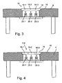
- Fig. 3 is a vertical section of the work board along the plane III-III of Fig. 2 ,
- Fig. 4 is a cross-section of a further embodiment mode of a pad printing machine's work board similar to Fig. 3 of the present invention
- Fig. 5 is a cross-section similar to that of Fig. 3 of a further embodiment mode of the present invention.
- Figs. 6, 7, 8 show the principle of the pad printing procedure, where Fig. 6 shows inking a print image on a printing block, Fig. 7 shows the ink transfer of the print image from the printing block to a pad and Fig. 8 the transfer of the print image from the pad to a workpiece to be printed.
- the pad printing machine 2 shown in Figs. 1 and 2 is fitted with a work board 4 configured in such manner in front of the printing machine that an operator 6 being in a work position before the work board 4 can reach across and over the work board 4 into a front insertion zone 8 of said printing machine to place workpieces from the work board 4 into the pad printing machine or remove them from it and put them on the work board.
- the insertion zone 8 in general may be an access zone in the pad printing machine also allowing checking or exchanging tools (for instance printing blocks, pads) and/or operational elements (for instance inks or ink cups).
- Fig. 1 shows the pad printing machine 2 resting on a base 2-2 and the work board 4 resting on legs 4-2.
- the pad printing machine 2 may rest on the work board 4 illustratively between the base 2-2 and the pad printing machine 2 and projecting forward.
- Another embodiment also is practical, namely the work board 4 being leg-less but instead being supported by the pad printing machine 2.
- a display 12 is operationally connected to a control unit 14 of the pad printing machine 2 either in hard-wired or wireless manner for the purpose of automatically displaying the particular printing machine status of at least two different machine states of the pad printing machine.
- the optical display 12 comprises an optical display area 16 configured on the work board 4 between the pad printing machine 2 and the operational position of the operator 6 running the pad printing machine across the work board 4 and within the field of view of this operator. In the preferred embodiment mode, the optic display 12 is integrated into the work board 4.
- the optical display area 16 preferably shall be flush with the surface 18 of the work board 4.
- the optical display area 16 per se may be part of the surface 18 of the work board 4.
- optical signals of the said display area may be a legible script and/or graphics and/or signal colors.
- the display 12 is designed to generate at least one optical signal for the machine state "machine intake zone 8 is accessible” and to one optical signal for the machine state "machine intake zone 8 is closed.
- the display 12 displays the signal color green denoting the machine state "machine intake zone 8 is accessible” in the optical display area 16 and the signal color red for the machine state "machine intake zone 8 is closed".
- the optical display 12 is designed to display further machine information in the optical display area 16, illustratively when a workpiece to be printed is properly positioned, or positioned and affixed, in the pad printing machine 2 and therefore is ready for printing.
- Another signal color may be used for such a purpose, for instance blue, or a combination of two or more colors.
- the optical display 16 may comprise a display strip 16-1 for instance for a red signal color, a display strip 16-2 for instance for a blue signal color and a display strip 16-3 for instance for a green signal color.
- all optical data, for instance signal colors may be displayed consecutively alternatingly in the same or in a single display strip.
- the signal colors may be generated in a number of ways, Illustratively the state of the art includes luminous sources of diverse colors such as incandescent bulbs or fluorescent lamps or halogen bulbs. Also light transparent glass or plastic elements of different colors are available.
- Fig. 3 cross-sectionally shows an optical display area in the form of light transmitting, transparent or white glass or plastic plate.
- an illustratively red bulb 20-1 below its display strip 16-2 a bulb 20-2 transmitting another signal color, for instance blue, and below the third display strip 16-3 a bulb 20-3 transmitting, another signal color, for instance green, all bulbs being part of the display 12.
- the optical display area 16 consists of three optical display strips of different colors, for instance one red light transmitting display strip 16-1, one blue light transmitting display strip 16-2 and one green light transmitting display strip 16-3, each above a bulb respectively 20-1, 20-2 and 20-3 each generating the same color light, for instance white, while being luminous at the surfaces of the display area 16 in the color of the particular display strip 16-1, 16-2 or 16-3.
- the pad printing machine of Figs. 1 and 2 may be fitted with a light beam barrier 40 in all embodiment modes, said light beam barrier being configured in the intake zone 8 where the operator 6 my insert the workpieces 10 into the pad printing machine 2 respectively retrieve them from it.
- the light beam barrier closes the intake zone 8 and thereby implements the operational state "machine intake zone closed", stopping the pad printing machine when the light barrier's beam is interrupted, for instance by a hand of the operator 6 blocking it.
- the light beam barrier 40 allows access to the intake zone 8 when the pad printing machine is not printing, that is in the operational state "machine intake zone is accessible”.
- Fig. 2 is a schematic topview of a light transmitter 42 and a light receiver 44 and the light barrier beam 46 of the light beam barrier 40.
- the light beam barrier 40 is operationally connected to the control unit 14 of the pad printing machine 2.
- Fig. 5 shows another preferred embodiment mode of the present invention.
- the optical display 212 consists of a display panel, for instance a flat monitor screen of which the light emitting elements may be driven by the control unit 14 of the pad printing machine to optically display the particular machine state in the optical display area 16 of the display panel.
- a number of applications are allowed by this design.
- One application consists in displaying various machine states in different display area strips 16-1, 16-2 and/or 16/3.
- Another consists in always displaying the particular machine state at the same site of the optical display area 16.
- the light generating elements may be LED's (Light Emitting Diodes), LCD's (Liquid Crystal Displays) or elements containing a gas or plasma.
- the optical display area 16 is mounted flush with the surface 18 of the work board 4.
- Figs, 6, 7 and 8 illustrate printing a workpiece 50 awaiting printing.
- ink from an ink cup 52 is deposited on the print image engraved or etched into the printing block 54 resting on a printing block support 58 in an ink receiving position retracted to the right as regards the drawings.
- Fig. 7 the printing block 54 is situated in an ink transfer position offset toward the left, wherein a pad 60 absorbs ink from the printing block print picture 56.
- Fig. 8 shows the printing block once more in the position of Fig. 6 and the pad 60 in a position where the workpiece 50 is being printed.
- Figs. 6, 7 and 8 denote those elements which are connected to each other by an omitted machine frame.
Landscapes
- Inking, Control Or Cleaning Of Printing Machines (AREA)
- Printing Methods (AREA)
Description
- The present invention relates to a pad printing machine fitted with a work board and defined in the preamble of claim 1.
- Pad printing machines are known for instance from
WO2004/113075 A1 andEP 1 053 882 B1 .EP-A-0581096 discloses a pad printing machine comprising an optical display operationally connected to a control unit of the pad printing machine in order to optically display the instantaneous machine states of at least two predetermined machine states. - Pad printing machines may be designed to be manually fed, the workpieces to be printed being manually inserted into, and removed from, the printing machine.
- Moreover the pad printing machines may be automated, the workpieces to be printed being fed to and removed from them in automated manner. Frequently enough, particular workpieces must be removed manually from such automated machines during operation, or be reinserted manually, for instance for quality control.
- Again tools and printing accessories such as printing blocks/plates, pads and ink cups sometimes must be checked or exchanged.
- The objective of the present invention is to make easier manual work for a pad printing machine operator.
- This problem is solved by the features of claim 1 of the present invention.
- Further features of this invention are defined in the dependent claims.
- The present invention is elucidated below and in relation to the appended drawings by means of preferred embodiment modes disclosing further features.
-
Fig. 1 is a schematic sideview of a pad printing machine fitted with a work board, -
Fig. 2 is a schematic topview of the pad printing machine and the work board ofFig. 1 , -
Fig. 3 is a vertical section of the work board along the plane III-III ofFig. 2 , -
Fig. 4 is a cross-section of a further embodiment mode of a pad printing machine's work board similar toFig. 3 of the present invention, -
Fig. 5 is a cross-section similar to that ofFig. 3 of a further embodiment mode of the present invention. -
Figs. 6, 7, 8 show the principle of the pad printing procedure, whereFig. 6 shows inking a print image on a printing block,Fig. 7 shows the ink transfer of the print image from the printing block to a pad andFig. 8 the transfer of the print image from the pad to a workpiece to be printed. - The
pad printing machine 2 shown inFigs. 1 and 2 is fitted with awork board 4 configured in such manner in front of the printing machine that anoperator 6 being in a work position before thework board 4 can reach across and over thework board 4 into afront insertion zone 8 of said printing machine to place workpieces from thework board 4 into the pad printing machine or remove them from it and put them on the work board. Theinsertion zone 8 in general may be an access zone in the pad printing machine also allowing checking or exchanging tools (for instance printing blocks, pads) and/or operational elements (for instance inks or ink cups). -
Fig. 1 shows thepad printing machine 2 resting on a base 2-2 and thework board 4 resting on legs 4-2. In another embodiment mode of the invention, thepad printing machine 2 may rest on thework board 4 illustratively between the base 2-2 and thepad printing machine 2 and projecting forward. Another embodiment also is practical, namely thework board 4 being leg-less but instead being supported by thepad printing machine 2. - A
display 12 is operationally connected to acontrol unit 14 of thepad printing machine 2 either in hard-wired or wireless manner for the purpose of automatically displaying the particular printing machine status of at least two different machine states of the pad printing machine. - The
optical display 12 comprises anoptical display area 16 configured on thework board 4 between thepad printing machine 2 and the operational position of theoperator 6 running the pad printing machine across thework board 4 and within the field of view of this operator. In the preferred embodiment mode, theoptic display 12 is integrated into thework board 4. - The
optical display area 16 preferably shall be flush with thesurface 18 of thework board 4. Theoptical display area 16 per se may be part of thesurface 18 of thework board 4. - The optical signals of the said display area may be a legible script and/or graphics and/or signal colors.
- In the preferred embodiment of the present invention, the
display 12 is designed to generate at least one optical signal for the machine state "machine intake zone 8 is accessible" and to one optical signal for the machine state "machine intake zone 8 is closed". - In a preferred embodiment mode of the present invention, the
display 12 displays the signal color green denoting the machine state "machine intake zone 8 is accessible" in theoptical display area 16 and the signal color red for the machine state "machine intake zone 8 is closed". - In a further preferred embodiment mode of the present invention, the
optical display 12 is designed to display further machine information in theoptical display area 16, illustratively when a workpiece to be printed is properly positioned, or positioned and affixed, in thepad printing machine 2 and therefore is ready for printing. Another signal color may be used for such a purpose, for instance blue, or a combination of two or more colors. - As shown by the topview of
Fig. 2 , theoptical display 16 may comprise a display strip 16-1 for instance for a red signal color, a display strip 16-2 for instance for a blue signal color and a display strip 16-3 for instance for a green signal color. In another embodiment mode, all optical data, for instance signal colors, may be displayed consecutively alternatingly in the same or in a single display strip. - The signal colors may be generated in a number of ways, Illustratively the state of the art includes luminous sources of diverse colors such as incandescent bulbs or fluorescent lamps or halogen bulbs. Also light transparent glass or plastic elements of different colors are available.
-
Fig. 3 cross-sectionally shows an optical display area in the form of light transmitting, transparent or white glass or plastic plate. Below said plate's display strip 16-1 is situated an illustratively red bulb 20-1, below its display strip 16-2 a bulb 20-2 transmitting another signal color, for instance blue, and below the third display strip 16-3 a bulb 20-3 transmitting, another signal color, for instance green, all bulbs being part of thedisplay 12. - In a further embodiment mode of the present invention shown in
Fig. 4 , theoptical display area 16 consists of three optical display strips of different colors, for instance one red light transmitting display strip 16-1, one blue light transmitting display strip 16-2 and one green light transmitting display strip 16-3, each above a bulb respectively 20-1, 20-2 and 20-3 each generating the same color light, for instance white, while being luminous at the surfaces of thedisplay area 16 in the color of the particular display strip 16-1, 16-2 or 16-3. - The pad printing machine of
Figs. 1 and 2 may be fitted with alight beam barrier 40 in all embodiment modes, said light beam barrier being configured in theintake zone 8 where theoperator 6 my insert theworkpieces 10 into thepad printing machine 2 respectively retrieve them from it. The light beam barrier closes theintake zone 8 and thereby implements the operational state "machine intake zone closed", stopping the pad printing machine when the light barrier's beam is interrupted, for instance by a hand of theoperator 6 blocking it. On the other hand thelight beam barrier 40 allows access to theintake zone 8 when the pad printing machine is not printing, that is in the operational state "machine intake zone is accessible". -
Fig. 2 is a schematic topview of alight transmitter 42 and alight receiver 44 and the light barrier beam 46 of thelight beam barrier 40. Thelight beam barrier 40 is operationally connected to thecontrol unit 14 of thepad printing machine 2. -
Fig. 5 shows another preferred embodiment mode of the present invention. In this embodiment mode, theoptical display 212 consists of a display panel, for instance a flat monitor screen of which the light emitting elements may be driven by thecontrol unit 14 of the pad printing machine to optically display the particular machine state in theoptical display area 16 of the display panel. A number of applications are allowed by this design. One application consists in displaying various machine states in different display area strips 16-1, 16-2 and/or 16/3. Another consists in always displaying the particular machine state at the same site of theoptical display area 16. The light generating elements may be LED's (Light Emitting Diodes), LCD's (Liquid Crystal Displays) or elements containing a gas or plasma. Preferably theoptical display area 16 is mounted flush with thesurface 18 of thework board 4. -
Figs, 6, 7 and 8 illustrate printing aworkpiece 50 awaiting printing. InFig. 6 , ink from anink cup 52 is deposited on the print image engraved or etched into theprinting block 54 resting on aprinting block support 58 in an ink receiving position retracted to the right as regards the drawings. - In
Fig. 7 theprinting block 54 is situated in an ink transfer position offset toward the left, wherein apad 60 absorbs ink from the printingblock print picture 56. -
Fig. 8 shows the printing block once more in the position ofFig. 6 and thepad 60 in a position where theworkpiece 50 is being printed. - The obliquely shaded portions shown in
Figs. 6, 7 and 8 denote those elements which are connected to each other by an omitted machine frame.
Claims (9)
- A pad printing machine fitted with a work board (4) that runs in front of the printing machine (2) in a manner that an operator situated before the work board (4) in a work position can reach beyond the work board (4) into the pad printing machine (2) for instance to move workpieces (10) from and above the work board (4) into the pad printing machine (2) or remove them from it and place them on the work board (4),
characterized
by comprising an optical display (12) operationally connected to a control unit (14) of the pad printing machine (2) in order to optically display the instantaneous machine states of at least two predetermined machine states, and by the optical display (12) comprising an optical display area (16) configured on the work board (4) between the pad printing machine (2) and the operational position of the operator (6) operating the pad printing machine (2) across the work board (4) within the field of view of this operator (6). - Pad printing machine as claimed in claim 1, characterized in that the optical display (12) is integrated into the work board (4).
- Pad printing machine as claimed in claim 2, characterized in that the optical display area (16) is configured in the surface (18) of the work board (4) and flush with said board's surface.
- Pad printing machine as claimed in one of the above claims, characterized by an optical signal for the machine state "machine intake zone is accessible" and by another optical signal for the machine state "machine intake zone is closed".
- Pad printing machine as claimed in claim 4, characterized by a further optical signal for at least one further machine state.
- Pad printing machine as claimed in claim 5, characterized in that the further optical signal relates to a machine state arising when a workpiece (10) is in a position to be processed in the pad printing machine (2).
- Pad printing machine as claimed in one of the above claims, characterized in that the optical display (16) is designed to display different luminous signal colors, a different signal color or color combination being assigned to each machine state.
- Pad printing machine as claimed in claim 7, characterized in that the color green is assigned to the machine state "machine intake zone is accessible" and the color red is assigned to the machine state "machine intake zone is closed".
- Pad printing machine as claimed in one of claims 4 through 8, characterized in that the pad printing machine (2) is fitted with a light beam barrier (40) operationally connected with the control unit (14) and configured in front of the intake zone (8) to monitor it, said operator (6) being able to place workpieces (10) into the pad printing machine (2) or remove them from it, the light beam barrier (40) closing the machine intake zone (8) during operation of the pad printing machine (2), thus being in the operational state "machine intake zone closed", and, when the light beam (46) is interrupted by someone, it shall automatically stop operation of the pad printing machine (2) by means of the control unit (14), the light beam barrier (40) opening the machine intake zone (8) when the pad printing machine (2) is shut down, namely in the operational state "machine intake zone open".
Applications Claiming Priority (2)
| Application Number | Priority Date | Filing Date | Title |
|---|---|---|---|
| DE200710018965 DE102007018965B4 (en) | 2007-04-21 | 2007-04-21 | Pad Printing Machine |
| PCT/IB2008/000730 WO2008129375A1 (en) | 2007-04-21 | 2008-03-27 | Pad printing machine |
Publications (2)
| Publication Number | Publication Date |
|---|---|
| EP2139687A1 EP2139687A1 (en) | 2010-01-06 |
| EP2139687B1 true EP2139687B1 (en) | 2014-12-17 |
Family
ID=39620219
Family Applications (1)
| Application Number | Title | Priority Date | Filing Date |
|---|---|---|---|
| EP08719375.1A Active EP2139687B1 (en) | 2007-04-21 | 2008-03-27 | Pad printing machine |
Country Status (4)
| Country | Link |
|---|---|
| US (1) | US8863658B2 (en) |
| EP (1) | EP2139687B1 (en) |
| DE (1) | DE102007018965B4 (en) |
| WO (1) | WO2008129375A1 (en) |
Family Cites Families (13)
| Publication number | Priority date | Publication date | Assignee | Title |
|---|---|---|---|---|
| US5136948A (en) * | 1990-10-31 | 1992-08-11 | Kabushiki Kaisha Shinkawa | Marking method and apparatus |
| US5392706A (en) | 1992-07-30 | 1995-02-28 | Markem Corporation | Pad transfer printing method |
| DE4239052C1 (en) * | 1992-11-20 | 1994-06-01 | Kba Planeta Ag | Sheet guide on printing machine - has grippers on cylinders and drums for sheet guide and format adjustment devices |
| US6748860B2 (en) * | 1994-04-15 | 2004-06-15 | Heidelberger Druckmaschinen Ag | Operating panel for a printing machine, inking control system for a printing machine, and inking control method |
| US6276266B1 (en) * | 1999-05-20 | 2001-08-21 | Illinois Tool Works, Inc. | Multicolor pad printing system |
| US6823780B2 (en) * | 2002-04-01 | 2004-11-30 | Atkins & Pearce, Inc. | Labeling system for a candlewick |
| AU2003287727A1 (en) * | 2002-11-13 | 2004-06-03 | Ackley Machine Corporation | Laser unit, inspection unit, method for inspecting pellet-shaped articles and pharmaceutical article |
| CN100382962C (en) * | 2003-06-20 | 2008-04-23 | Itw莫克洛有限公司 | Movable pad holder for pad printing machines |
| US6975827B2 (en) * | 2003-07-28 | 2005-12-13 | Wessells Philip G | Apparatus and method for image capture and pad transfer |
| US6983688B1 (en) * | 2003-08-26 | 2006-01-10 | The Gem Group, Inc. | Decoration for bags and cases and method for applying the same |
| DE10341007B4 (en) * | 2003-09-05 | 2005-12-08 | Leuze Lumiflex Gmbh + Co. Kg | Light barrier arrangement |
| US7474983B2 (en) * | 2005-01-05 | 2009-01-06 | Massachusetts Institute Of Technology | Method for object identification and sensing in a bounded interaction space |
| JP2006235157A (en) * | 2005-02-24 | 2006-09-07 | Seiko Epson Corp | Image display device, image display method, and program |
-
2007
- 2007-04-21 DE DE200710018965 patent/DE102007018965B4/en active Active
-
2008
- 2008-03-27 WO PCT/IB2008/000730 patent/WO2008129375A1/en not_active Ceased
- 2008-03-27 EP EP08719375.1A patent/EP2139687B1/en active Active
- 2008-03-27 US US12/529,256 patent/US8863658B2/en active Active
Also Published As
| Publication number | Publication date |
|---|---|
| DE102007018965B4 (en) | 2011-02-10 |
| EP2139687A1 (en) | 2010-01-06 |
| WO2008129375A1 (en) | 2008-10-30 |
| US8863658B2 (en) | 2014-10-21 |
| DE102007018965A1 (en) | 2008-10-23 |
| US20100031836A1 (en) | 2010-02-11 |
Similar Documents
| Publication | Publication Date | Title |
|---|---|---|
| US20120133716A1 (en) | Ultraviolet irradiation device and printing device | |
| US10408432B2 (en) | Backlit display assembly | |
| US6979114B2 (en) | Liquid crystal display and light source device thereof | |
| TW200619773A (en) | Backlight device and transmissive liquid crystal display device | |
| JPH02501011A (en) | For example, an indicator device with a liquid crystal cell for automobiles | |
| CN102170975A (en) | Device for measuring the relative positioning of the image-forming point of a laser-displacement sensor and the outlet port of the nozzle of a head unit, paste dispenser to which this device for measuring relative positioning is fitted, and a method | |
| EP3535620B1 (en) | Display apparatus | |
| EP2139687B1 (en) | Pad printing machine | |
| RU2471222C2 (en) | Method and apparatus for detecting and eliminating malfunctions in machines | |
| ITMO20090317A1 (en) | PORTABLE DEVICE AND METHOD FOR READING CODIFIED INFORMATION | |
| US20070059991A1 (en) | Electronic device and liquid crystal display device | |
| US11642904B2 (en) | Electronic hand stamp | |
| CN211867951U (en) | Drilling machine | |
| CN210513014U (en) | Online TV backplate vision inspection machine | |
| TW200606523A (en) | Liquid crystal display and reflecting member for the same | |
| ES2258686T3 (en) | TRANSPARENT PLASTIC PRINTED DISPLAY INSERT FOR THE DISPLAY SUPPORT OF AN APPLIANCES. | |
| CN216435328U (en) | Double-layer color display device for automobile instrument panel | |
| KR20140075324A (en) | Pattern image projector | |
| CN218209060U (en) | Brightening stroboscopic multispectral strip-shaped light source | |
| CN216623622U (en) | Color display device for automobile instrument panel | |
| KR100750515B1 (en) | Flat Panel Display Screen Printer Unit | |
| CN212584792U (en) | Multi-pattern spotlight | |
| US9057515B2 (en) | Illuminating device for machine tool | |
| KR20150112456A (en) | Virtual Traffic Sign Display Device | |
| JP3191621U (en) | Ink zone operation panel with touch screen |
Legal Events
| Date | Code | Title | Description |
|---|---|---|---|
| PUAI | Public reference made under article 153(3) epc to a published international application that has entered the european phase |
Free format text: ORIGINAL CODE: 0009012 |
|
| 17P | Request for examination filed |
Effective date: 20090814 |
|
| AK | Designated contracting states |
Kind code of ref document: A1 Designated state(s): AT BE BG CH CY CZ DE DK EE ES FI FR GB GR HR HU IE IS IT LI LT LU LV MC MT NL NO PL PT RO SE SI SK TR |
|
| DAX | Request for extension of the european patent (deleted) | ||
| GRAP | Despatch of communication of intention to grant a patent |
Free format text: ORIGINAL CODE: EPIDOSNIGR1 |
|
| INTG | Intention to grant announced |
Effective date: 20140819 |
|
| GRAS | Grant fee paid |
Free format text: ORIGINAL CODE: EPIDOSNIGR3 |
|
| GRAA | (expected) grant |
Free format text: ORIGINAL CODE: 0009210 |
|
| AK | Designated contracting states |
Kind code of ref document: B1 Designated state(s): AT BE BG CH CY CZ DE DK EE ES FI FR GB GR HR HU IE IS IT LI LT LU LV MC MT NL NO PL PT RO SE SI SK TR |
|
| REG | Reference to a national code |
Ref country code: GB Ref legal event code: FG4D |
|
| REG | Reference to a national code |
Ref country code: CH Ref legal event code: EP |
|
| REG | Reference to a national code |
Ref country code: IE Ref legal event code: FG4D |
|
| REG | Reference to a national code |
Ref country code: AT Ref legal event code: REF Ref document number: 701574 Country of ref document: AT Kind code of ref document: T Effective date: 20150115 |
|
| REG | Reference to a national code |
Ref country code: DE Ref legal event code: R096 Ref document number: 602008035874 Country of ref document: DE Effective date: 20150129 |
|
| PG25 | Lapsed in a contracting state [announced via postgrant information from national office to epo] |
Ref country code: FI Free format text: LAPSE BECAUSE OF FAILURE TO SUBMIT A TRANSLATION OF THE DESCRIPTION OR TO PAY THE FEE WITHIN THE PRESCRIBED TIME-LIMIT Effective date: 20141217 Ref country code: NO Free format text: LAPSE BECAUSE OF FAILURE TO SUBMIT A TRANSLATION OF THE DESCRIPTION OR TO PAY THE FEE WITHIN THE PRESCRIBED TIME-LIMIT Effective date: 20150317 Ref country code: LT Free format text: LAPSE BECAUSE OF FAILURE TO SUBMIT A TRANSLATION OF THE DESCRIPTION OR TO PAY THE FEE WITHIN THE PRESCRIBED TIME-LIMIT Effective date: 20141217 |
|
| REG | Reference to a national code |
Ref country code: LT Ref legal event code: MG4D |
|
| PG25 | Lapsed in a contracting state [announced via postgrant information from national office to epo] |
Ref country code: LV Free format text: LAPSE BECAUSE OF FAILURE TO SUBMIT A TRANSLATION OF THE DESCRIPTION OR TO PAY THE FEE WITHIN THE PRESCRIBED TIME-LIMIT Effective date: 20141217 Ref country code: HR Free format text: LAPSE BECAUSE OF FAILURE TO SUBMIT A TRANSLATION OF THE DESCRIPTION OR TO PAY THE FEE WITHIN THE PRESCRIBED TIME-LIMIT Effective date: 20141217 Ref country code: GR Free format text: LAPSE BECAUSE OF FAILURE TO SUBMIT A TRANSLATION OF THE DESCRIPTION OR TO PAY THE FEE WITHIN THE PRESCRIBED TIME-LIMIT Effective date: 20150318 Ref country code: SE Free format text: LAPSE BECAUSE OF FAILURE TO SUBMIT A TRANSLATION OF THE DESCRIPTION OR TO PAY THE FEE WITHIN THE PRESCRIBED TIME-LIMIT Effective date: 20141217 |
|
| REG | Reference to a national code |
Ref country code: AT Ref legal event code: MK05 Ref document number: 701574 Country of ref document: AT Kind code of ref document: T Effective date: 20141217 |
|
| PG25 | Lapsed in a contracting state [announced via postgrant information from national office to epo] |
Ref country code: NL Free format text: LAPSE BECAUSE OF FAILURE TO SUBMIT A TRANSLATION OF THE DESCRIPTION OR TO PAY THE FEE WITHIN THE PRESCRIBED TIME-LIMIT Effective date: 20141217 |
|
| PG25 | Lapsed in a contracting state [announced via postgrant information from national office to epo] |
Ref country code: EE Free format text: LAPSE BECAUSE OF FAILURE TO SUBMIT A TRANSLATION OF THE DESCRIPTION OR TO PAY THE FEE WITHIN THE PRESCRIBED TIME-LIMIT Effective date: 20141217 Ref country code: CZ Free format text: LAPSE BECAUSE OF FAILURE TO SUBMIT A TRANSLATION OF THE DESCRIPTION OR TO PAY THE FEE WITHIN THE PRESCRIBED TIME-LIMIT Effective date: 20141217 Ref country code: SK Free format text: LAPSE BECAUSE OF FAILURE TO SUBMIT A TRANSLATION OF THE DESCRIPTION OR TO PAY THE FEE WITHIN THE PRESCRIBED TIME-LIMIT Effective date: 20141217 Ref country code: RO Free format text: LAPSE BECAUSE OF FAILURE TO SUBMIT A TRANSLATION OF THE DESCRIPTION OR TO PAY THE FEE WITHIN THE PRESCRIBED TIME-LIMIT Effective date: 20141217 Ref country code: ES Free format text: LAPSE BECAUSE OF FAILURE TO SUBMIT A TRANSLATION OF THE DESCRIPTION OR TO PAY THE FEE WITHIN THE PRESCRIBED TIME-LIMIT Effective date: 20141217 |
|
| PG25 | Lapsed in a contracting state [announced via postgrant information from national office to epo] |
Ref country code: AT Free format text: LAPSE BECAUSE OF FAILURE TO SUBMIT A TRANSLATION OF THE DESCRIPTION OR TO PAY THE FEE WITHIN THE PRESCRIBED TIME-LIMIT Effective date: 20141217 Ref country code: PL Free format text: LAPSE BECAUSE OF FAILURE TO SUBMIT A TRANSLATION OF THE DESCRIPTION OR TO PAY THE FEE WITHIN THE PRESCRIBED TIME-LIMIT Effective date: 20141217 Ref country code: IS Free format text: LAPSE BECAUSE OF FAILURE TO SUBMIT A TRANSLATION OF THE DESCRIPTION OR TO PAY THE FEE WITHIN THE PRESCRIBED TIME-LIMIT Effective date: 20150417 |
|
| REG | Reference to a national code |
Ref country code: DE Ref legal event code: R097 Ref document number: 602008035874 Country of ref document: DE |
|
| PLBE | No opposition filed within time limit |
Free format text: ORIGINAL CODE: 0009261 |
|
| STAA | Information on the status of an ep patent application or granted ep patent |
Free format text: STATUS: NO OPPOSITION FILED WITHIN TIME LIMIT |
|
| PG25 | Lapsed in a contracting state [announced via postgrant information from national office to epo] |
Ref country code: MC Free format text: LAPSE BECAUSE OF FAILURE TO SUBMIT A TRANSLATION OF THE DESCRIPTION OR TO PAY THE FEE WITHIN THE PRESCRIBED TIME-LIMIT Effective date: 20141217 Ref country code: DK Free format text: LAPSE BECAUSE OF FAILURE TO SUBMIT A TRANSLATION OF THE DESCRIPTION OR TO PAY THE FEE WITHIN THE PRESCRIBED TIME-LIMIT Effective date: 20141217 Ref country code: LU Free format text: LAPSE BECAUSE OF FAILURE TO SUBMIT A TRANSLATION OF THE DESCRIPTION OR TO PAY THE FEE WITHIN THE PRESCRIBED TIME-LIMIT Effective date: 20150327 |
|
| REG | Reference to a national code |
Ref country code: CH Ref legal event code: PL |
|
| 26N | No opposition filed |
Effective date: 20150918 |
|
| GBPC | Gb: european patent ceased through non-payment of renewal fee |
Effective date: 20150327 |
|
| REG | Reference to a national code |
Ref country code: IE Ref legal event code: MM4A |
|
| PG25 | Lapsed in a contracting state [announced via postgrant information from national office to epo] |
Ref country code: GB Free format text: LAPSE BECAUSE OF NON-PAYMENT OF DUE FEES Effective date: 20150327 Ref country code: IE Free format text: LAPSE BECAUSE OF NON-PAYMENT OF DUE FEES Effective date: 20150327 Ref country code: CH Free format text: LAPSE BECAUSE OF NON-PAYMENT OF DUE FEES Effective date: 20150331 Ref country code: LI Free format text: LAPSE BECAUSE OF NON-PAYMENT OF DUE FEES Effective date: 20150331 |
|
| PG25 | Lapsed in a contracting state [announced via postgrant information from national office to epo] |
Ref country code: SI Free format text: LAPSE BECAUSE OF FAILURE TO SUBMIT A TRANSLATION OF THE DESCRIPTION OR TO PAY THE FEE WITHIN THE PRESCRIBED TIME-LIMIT Effective date: 20141217 |
|
| REG | Reference to a national code |
Ref country code: FR Ref legal event code: PLFP Year of fee payment: 9 |
|
| PG25 | Lapsed in a contracting state [announced via postgrant information from national office to epo] |
Ref country code: BE Free format text: LAPSE BECAUSE OF FAILURE TO SUBMIT A TRANSLATION OF THE DESCRIPTION OR TO PAY THE FEE WITHIN THE PRESCRIBED TIME-LIMIT Effective date: 20141217 |
|
| PG25 | Lapsed in a contracting state [announced via postgrant information from national office to epo] |
Ref country code: MT Free format text: LAPSE BECAUSE OF FAILURE TO SUBMIT A TRANSLATION OF THE DESCRIPTION OR TO PAY THE FEE WITHIN THE PRESCRIBED TIME-LIMIT Effective date: 20141217 |
|
| REG | Reference to a national code |
Ref country code: FR Ref legal event code: PLFP Year of fee payment: 10 |
|
| PG25 | Lapsed in a contracting state [announced via postgrant information from national office to epo] |
Ref country code: BG Free format text: LAPSE BECAUSE OF FAILURE TO SUBMIT A TRANSLATION OF THE DESCRIPTION OR TO PAY THE FEE WITHIN THE PRESCRIBED TIME-LIMIT Effective date: 20141217 Ref country code: HU Free format text: LAPSE BECAUSE OF FAILURE TO SUBMIT A TRANSLATION OF THE DESCRIPTION OR TO PAY THE FEE WITHIN THE PRESCRIBED TIME-LIMIT; INVALID AB INITIO Effective date: 20080327 |
|
| PG25 | Lapsed in a contracting state [announced via postgrant information from national office to epo] |
Ref country code: CY Free format text: LAPSE BECAUSE OF FAILURE TO SUBMIT A TRANSLATION OF THE DESCRIPTION OR TO PAY THE FEE WITHIN THE PRESCRIBED TIME-LIMIT Effective date: 20141217 |
|
| PG25 | Lapsed in a contracting state [announced via postgrant information from national office to epo] |
Ref country code: PT Free format text: LAPSE BECAUSE OF FAILURE TO SUBMIT A TRANSLATION OF THE DESCRIPTION OR TO PAY THE FEE WITHIN THE PRESCRIBED TIME-LIMIT Effective date: 20150417 |
|
| PG25 | Lapsed in a contracting state [announced via postgrant information from national office to epo] |
Ref country code: TR Free format text: LAPSE BECAUSE OF FAILURE TO SUBMIT A TRANSLATION OF THE DESCRIPTION OR TO PAY THE FEE WITHIN THE PRESCRIBED TIME-LIMIT Effective date: 20141217 |
|
| REG | Reference to a national code |
Ref country code: FR Ref legal event code: PLFP Year of fee payment: 11 |
|
| P01 | Opt-out of the competence of the unified patent court (upc) registered |
Effective date: 20231101 |
|
| PGFP | Annual fee paid to national office [announced via postgrant information from national office to epo] |
Ref country code: DE Payment date: 20250327 Year of fee payment: 18 |
|
| PGFP | Annual fee paid to national office [announced via postgrant information from national office to epo] |
Ref country code: FR Payment date: 20250325 Year of fee payment: 18 |
|
| PGFP | Annual fee paid to national office [announced via postgrant information from national office to epo] |
Ref country code: IT Payment date: 20250319 Year of fee payment: 18 |