EP2139607B1 - Dispensing device - Google Patents
Dispensing device Download PDFInfo
- Publication number
- EP2139607B1 EP2139607B1 EP07747292.6A EP07747292A EP2139607B1 EP 2139607 B1 EP2139607 B1 EP 2139607B1 EP 07747292 A EP07747292 A EP 07747292A EP 2139607 B1 EP2139607 B1 EP 2139607B1
- Authority
- EP
- European Patent Office
- Prior art keywords
- foam
- pump
- inlet
- dispensing
- dispensing device
- Prior art date
- Legal status (The legal status is an assumption and is not a legal conclusion. Google has not performed a legal analysis and makes no representation as to the accuracy of the status listed.)
- Not-in-force
Links
- 239000007788 liquid Substances 0.000 claims description 67
- 239000006260 foam Substances 0.000 claims description 50
- 239000000463 material Substances 0.000 claims description 8
- 238000000034 method Methods 0.000 claims description 6
- 238000004891 communication Methods 0.000 claims description 4
- 239000012530 fluid Substances 0.000 claims description 4
- 239000000203 mixture Substances 0.000 description 7
- 238000010276 construction Methods 0.000 description 2
- 239000000344 soap Substances 0.000 description 2
- 230000001131 transforming effect Effects 0.000 description 2
- 230000015572 biosynthetic process Effects 0.000 description 1
- 238000004140 cleaning Methods 0.000 description 1
- 230000006835 compression Effects 0.000 description 1
- 238000007906 compression Methods 0.000 description 1
- 230000003247 decreasing effect Effects 0.000 description 1
- 230000009977 dual effect Effects 0.000 description 1
- 239000006261 foam material Substances 0.000 description 1
- 239000011148 porous material Substances 0.000 description 1
- 238000003825 pressing Methods 0.000 description 1
- 238000007789 sealing Methods 0.000 description 1
- 239000002453 shampoo Substances 0.000 description 1
- 238000004904 shortening Methods 0.000 description 1
- 230000009466 transformation Effects 0.000 description 1
- 238000011144 upstream manufacturing Methods 0.000 description 1
- XLYOFNOQVPJJNP-UHFFFAOYSA-N water Substances O XLYOFNOQVPJJNP-UHFFFAOYSA-N 0.000 description 1
Images
Classifications
-
- B—PERFORMING OPERATIONS; TRANSPORTING
- B05—SPRAYING OR ATOMISING IN GENERAL; APPLYING FLUENT MATERIALS TO SURFACES, IN GENERAL
- B05B—SPRAYING APPARATUS; ATOMISING APPARATUS; NOZZLES
- B05B7/00—Spraying apparatus for discharge of liquids or other fluent materials from two or more sources, e.g. of liquid and air, of powder and gas
- B05B7/0018—Spraying apparatus for discharge of liquids or other fluent materials from two or more sources, e.g. of liquid and air, of powder and gas with devices for making foam
-
- B—PERFORMING OPERATIONS; TRANSPORTING
- B05—SPRAYING OR ATOMISING IN GENERAL; APPLYING FLUENT MATERIALS TO SURFACES, IN GENERAL
- B05B—SPRAYING APPARATUS; ATOMISING APPARATUS; NOZZLES
- B05B11/00—Single-unit hand-held apparatus in which flow of contents is produced by the muscular force of the operator at the moment of use
- B05B11/01—Single-unit hand-held apparatus in which flow of contents is produced by the muscular force of the operator at the moment of use characterised by the means producing the flow
- B05B11/10—Pump arrangements for transferring the contents from the container to a pump chamber by a sucking effect and forcing the contents out through the dispensing nozzle
- B05B11/1028—Pumps having a pumping chamber with a deformable wall
- B05B11/1035—Pumps having a pumping chamber with a deformable wall the pumping chamber being a bellow
-
- B—PERFORMING OPERATIONS; TRANSPORTING
- B05—SPRAYING OR ATOMISING IN GENERAL; APPLYING FLUENT MATERIALS TO SURFACES, IN GENERAL
- B05B—SPRAYING APPARATUS; ATOMISING APPARATUS; NOZZLES
- B05B11/00—Single-unit hand-held apparatus in which flow of contents is produced by the muscular force of the operator at the moment of use
- B05B11/01—Single-unit hand-held apparatus in which flow of contents is produced by the muscular force of the operator at the moment of use characterised by the means producing the flow
- B05B11/10—Pump arrangements for transferring the contents from the container to a pump chamber by a sucking effect and forcing the contents out through the dispensing nozzle
- B05B11/1087—Combination of liquid and air pumps
-
- B—PERFORMING OPERATIONS; TRANSPORTING
- B05—SPRAYING OR ATOMISING IN GENERAL; APPLYING FLUENT MATERIALS TO SURFACES, IN GENERAL
- B05B—SPRAYING APPARATUS; ATOMISING APPARATUS; NOZZLES
- B05B11/00—Single-unit hand-held apparatus in which flow of contents is produced by the muscular force of the operator at the moment of use
- B05B11/01—Single-unit hand-held apparatus in which flow of contents is produced by the muscular force of the operator at the moment of use characterised by the means producing the flow
- B05B11/10—Pump arrangements for transferring the contents from the container to a pump chamber by a sucking effect and forcing the contents out through the dispensing nozzle
- B05B11/1098—Air being permanently entrapped or sucked into the liquid pump chamber
-
- B—PERFORMING OPERATIONS; TRANSPORTING
- B05—SPRAYING OR ATOMISING IN GENERAL; APPLYING FLUENT MATERIALS TO SURFACES, IN GENERAL
- B05B—SPRAYING APPARATUS; ATOMISING APPARATUS; NOZZLES
- B05B15/00—Details of spraying plant or spraying apparatus not otherwise provided for; Accessories
- B05B15/30—Dip tubes
-
- B—PERFORMING OPERATIONS; TRANSPORTING
- B05—SPRAYING OR ATOMISING IN GENERAL; APPLYING FLUENT MATERIALS TO SURFACES, IN GENERAL
- B05B—SPRAYING APPARATUS; ATOMISING APPARATUS; NOZZLES
- B05B7/00—Spraying apparatus for discharge of liquids or other fluent materials from two or more sources, e.g. of liquid and air, of powder and gas
- B05B7/0018—Spraying apparatus for discharge of liquids or other fluent materials from two or more sources, e.g. of liquid and air, of powder and gas with devices for making foam
- B05B7/0025—Spraying apparatus for discharge of liquids or other fluent materials from two or more sources, e.g. of liquid and air, of powder and gas with devices for making foam with a compressed gas supply
- B05B7/0031—Spraying apparatus for discharge of liquids or other fluent materials from two or more sources, e.g. of liquid and air, of powder and gas with devices for making foam with a compressed gas supply with disturbing means promoting mixing, e.g. balls, crowns
- B05B7/0037—Spraying apparatus for discharge of liquids or other fluent materials from two or more sources, e.g. of liquid and air, of powder and gas with devices for making foam with a compressed gas supply with disturbing means promoting mixing, e.g. balls, crowns including sieves, porous members or the like
-
- B—PERFORMING OPERATIONS; TRANSPORTING
- B05—SPRAYING OR ATOMISING IN GENERAL; APPLYING FLUENT MATERIALS TO SURFACES, IN GENERAL
- B05B—SPRAYING APPARATUS; ATOMISING APPARATUS; NOZZLES
- B05B7/00—Spraying apparatus for discharge of liquids or other fluent materials from two or more sources, e.g. of liquid and air, of powder and gas
- B05B7/0018—Spraying apparatus for discharge of liquids or other fluent materials from two or more sources, e.g. of liquid and air, of powder and gas with devices for making foam
- B05B7/005—Spraying apparatus for discharge of liquids or other fluent materials from two or more sources, e.g. of liquid and air, of powder and gas with devices for making foam wherein ambient air is aspirated by a liquid flow
-
- Y—GENERAL TAGGING OF NEW TECHNOLOGICAL DEVELOPMENTS; GENERAL TAGGING OF CROSS-SECTIONAL TECHNOLOGIES SPANNING OVER SEVERAL SECTIONS OF THE IPC; TECHNICAL SUBJECTS COVERED BY FORMER USPC CROSS-REFERENCE ART COLLECTIONS [XRACs] AND DIGESTS
- Y10—TECHNICAL SUBJECTS COVERED BY FORMER USPC
- Y10T—TECHNICAL SUBJECTS COVERED BY FORMER US CLASSIFICATION
- Y10T29/00—Metal working
- Y10T29/49—Method of mechanical manufacture
- Y10T29/49826—Assembling or joining
Definitions
- the present invention relates to a dispensing device and a method for providing a dispensing device. Furthermore, the invention relates to a foam-forming device to be mounted in a dispensing device.
- a foam-forming device and a method for providing a foam dispensing device is known from US 4932567 which forms a basis for claims 1 and 13.
- Dispensing devices for liquid comprising a container and a dispensing assembly mounted on or in an opening of the container are well-known.
- the dispensing assembly which usually is to be operated by hand comprises a pump having an inlet and an outlet.
- the inlet is in fluid communication with the interior of the container, for instance via a dip tube, one end of the dip tube being connected to the inlet, the other end being arranged in a bottom portion of the interior of the container.
- liquid is drawn into the pump, and dispensed via the outlet through a dispensing opening.
- Such dispensing devices are applied for numerous applications, such as soap, shampoo, cleaning liquids, etc.
- foam dispensing devices for the dispensing of liquid, propellant-free foam dispensers.
- foam dispensing devices comprise an air pump and a liquid pump which can simultaneously be actuated by a common operating button.
- liquid and air pump Upon actuation of the liquid and air pump, by a common actuation device, liquid and air are mixed in a mixing chamber and formed into a foam, which foam is dispensed through a dispensing opening.
- foam dispensing device is for instance disclosed in US 5,271,530 or EP 565 713 .
- a disadvantage of these known foam dispensers is that for the provision of two separate pumps, a relatively large number of parts is needed, and the construction is rather complex. Furthermore, some difficulties may occur with respect to the sealing of the outlets of both pumps. Also, the air pump, in particular a piston air pump may be sensitive for the presence of water and/or soap.
- GB 821793 another foam dispensing device is disclosed.
- a single liquid bellows pump is used for the dispensing of foam.
- the liquid supply channel i.e. the liquid path from the liquid held in the container to the inlet of the pump
- a chamber is provided in this chamber.
- an air inlet opening is provided by means of an air conduit connected to the environment outside the foam dispensing device.
- the foam dispensing device as disclosed in GB 821793 provides a less complex alternative for the known dual pump foam dispensing device, it comprises a number of practical disadvantages with the result that the dispensing device has not been successfully introduced on the market.
- the aim of the present invention is to provide a dispensing device for the dispensing of a foam, which provides advantages over prior art foam dispensing devices.
- the present invention provides a dispensing device according to claim 2.
- a dispensing device having a single pump and being capable of dispensing a foam.
- the presence of a one-way valve in the channel upstream of the air inlet opening is advantageous as the liquid which is present in the channel may be held in the channel after dispensing of a foam.
- the pump does not again have to draw liquid in the channel up to the one-way valve.
- the liquid can directly.be pumped out of the channel, mixed with air and drawn into the pump chamber of the pump, and subsequently be dispensed through the dispensing opening. This reduces the number of pump strokes to be made with the pump before actually dispensing foam after the first use of the foam dispensing device. This is an important advantage as the user may be annoyed by idle pump strokes of the dispensing device.
- the one-way valve is preferably arranged at or above half the height of said channel, more preferably at or above 75% of the height of said channel.
- the dispensing device comprises a foam-forming device defining at least a part of said channel and defining at least partially said air inlet opening.
- the foam-forming device is a device which makes it possible to form a foam using a liquid pump. The forming of the foam does not have to actually take place in the foam-forming device.
- the foam-forming device defines at least partially the air inlet opening so that mounting of the foam-forming device provides the air inlet.opening in the channel running to the inlet of the pump.
- the foam-forming device comprises said one-way valve.
- the dispensing assembly comprises a dip tube defining at least a part of said channel.
- the dip tube may be used to bridge the distance between the inlet of the pump and the bottom portion of the interior of the container so that in an upright position of the dispensing device the container can be emptied via the dip tube.
- the foam-forming device is arranged between said pump inlet and said dip tube.
- Dip tubes are often used in dispensing devices. By designing the foam-forming device in such a way that it can placed between the pump inlet and the dip tube of an existing liquid dispensing device, the liquid dispensing device can be easily transformed into a foam dispensing device without the need to make any fundamental changes to the liquid dispensing device except the mounting of the foam-dispensing device and shortening the dip tube.
- the dip tube may however also be integrally provided on the foam-forming device, or another dip tube may be provided.
- a sponge or sponge-like material is arranged in a pump chamber of said pump.
- the sponge or sponge-like material can hold an amount of liquid and air pumped into the pump chamber of the pump, but not yet dispensed through the outlet of the pump.
- the sponge or sponge-like material may substantially improve the forming of foam in the dispensing device, in particular since it is squeezed every time the pump is actuated.
- the pump of the dispensing device may be a bellows pump, piston pump or any other type of pump suitable for the dispensing of a foamable liquid.
- the pump is preferably manually actuable.
- two or more air inlet openings may be provided in said channel.
- the two or more inlet openings are preferably evenly distributed about the circumference of the channel.
- the invention also relates to a method for providing a foam dispensing device according to claim 13.
- the invention also relates to a foam-forming device (according to claim 1) mountable on or in an inlet of a liquid pump, defining at least a part of a liquid supply channel, said foam forming assembly further comprising a one-way valve and defining at least partially an air inlet opening, said air inlet opening being provided between said inlet and said one-way valve.
- FIG. 1 shows a foam dispensing device according to the invention generally indicated with the reference numeral 1.
- the foam dispensing device 1 comprises a container 2 (In Figure 1 only the top part is shown) holding a quantity of foamable liquid 3.
- a dispensing assembly 4 is mounted in the container 2 in Figure 1 .
- the dispensing assembly 4 comprises a bellows type pump 5 having an inlet 6, a pump chamber 7 and an outlet 8. In the inlet 6 an inlet valve 9 is provided, and in the outlet 8 an outlet valve 10 is provided.
- the top portion 11 of the bellows pump 5 serves as actuation button and can be actuated manually and reciprocally in vertical direction by pressing the top portion downwards.
- the cylindrical bellows side 12 is designed to bias the top portion 11 back in the top position as shown in Figure 1 , when no downwards pressure is exerted on the top portion 11. This biasing may be provided by the elasticity of the bellows material itself or may be provided by a spring, for instance embedded in the bellows material.
- the inlet 6 of the pump 5 is connected to a top side of a foam-forming device 14.
- the bottom side of the foam-forming device 14 is connected to a dip tube 15.
- the foam-forming device and the dip tube 15 define a channel 16 which runs from a bottom portion of the interior of the container 2 to the inlet 6 of the pump 5.
- the dip tube may be an integral part of the foam-forming device 14.
- a separate dip tube has the advantage that the foam-forming device 14 can easily be adapted for different kinds of containers by providing dip tubes with different shapes and/or heights.
- the dip tube may be integral with the foam-forming device, and optionally a dip tube of suitable length may be connected to the dip tube to adapt the height of the channel 16 to the container.
- the foam-forming device 14 defines an air inlet opening 17 which provides an air path between the channel 16 and an air containing top portion of the interior of the container 2.
- a sponge 19 is arranged, which is for instance made of a closed or open cell foam material. Any other sponge-like material may also be applied.
- This sponge 19 is compressible and may contain a quantity of liquid-air mixture.
- the sponge 19 is sized in such a way that during the compressing stroke of the bellows pump 5, the sponge 19 is compressed, and during the upwards movement the sponge 19 may decompress to substantially its original size. This compressing and decompressing of the sponge 19 improves substantially the.quality of the foam dispensed by the foam dispensing device 1.
- a one-way valve 20 is provided in channel 16. This one-way valve 20 allows a liquid flow in the direction of the pump, but does not allow a flow in the opposite direction. Thus, when no liquid is drawn to the pump chamber 7, the one-way valve 20 will close the channel 16. As a result, it is possible to maintain the liquid column in the channel 16 avoiding the need of the extra strokes to pump the liquid back into the channel.
- the one-way valve 20 may be provided in the dip tube.
- the one-way valve 20 may be any passive or active valve which substantially avoids that liquid present in the channel 16 under the one-way valve 20 will not run back into the container 2.
- the foam-forming device 14 comprises a tube shaped top end 21 which can be mounted on or in the inlet 6 of the pump.
- a tube shaped bottom end 22 of the foam-forming device 14 is connected to the dip tube 15.
- the tube shaped top end 21 of the foam-forming device 14 has substantially the same shape as the top end of the dip tube 15, and/or that the tube shaped bottom end 22 of the foam-forming device 14 of the container has substantially the same shape as the inlet 6 of the pump 5.
- the foam-forming device 14 can simply be placed between the inlet 6 of a liquid pump and the dip tube of said pump therewith transforming a known liquid dispensing device into a foam dispensing device.
- a known liquid dispensing device suitable for such transformation is for instance disclosed in WO03/035274 A1 . In this publication the functioning of this liquid dispensing device is explained in more detail.
- the dip tube 15 of the known dispensing device may be too long for the dispensing device due to the height of the foam-forming device. In such case the dip tube 15 may be shortened or replaced by another one. Also a dip tube may be integrally provided on the foam-forming device 14.
- the foam-forming device 14 further comprises a number of grooves 23.
- the presence of the grooves 23 in the foam-forming device 14 define when the foam-forming device 14 is placed on the inlet 6 of the pump 5 the one or more air inlet openings 17 required for the provision of air into the liquid flow.
- through-going holes may be provided in the foam-forming device 14 running from the outer surface 24 of the foam-forming device to the channel 16 at least partially defined by the inner surface 25 of the foam-forming device 14.
- air inlet conduits may be provided which run from the channel 16 to the environment outside the dispensing device. Such air inlet conduits may be advantageous in the case the container is a compressible container which is not aerated, or any other type of container which does not comprise air. Such containers are for instance used for liquids which easily oxidize or are easily contaminated.
- the transverse dimension of the air inlet openings 17 is not greater than about 1 mm, more preferably smaller than 0,25 mm.
- grooves may be provided on the inlet 6 or both the inlet 6 and the foam-forming device 14 to provide the air inlet openings 17 for forming a foam.
- the air inlet openings may be formed as generally described in WO 91/01259 .
- An exemplary embodiment of such foam-forming device is shown in figure 3 .
- This foam-forming device.30 comprises an end surface 31 which is provided with grooves 32.
- the end surface 31 abuts, when mounted on the inlet 6 of a liquid pump, against an end surface 33 of the inlet 6 of the liquid pump.
- the grooves 32 and the end surface 33 define horizontal air channels 34.
- the foam-forming device further comprises a cylindrical shoulder 35 which is at the inside also provided with vertical grooves 36.
- The.outer surface of the inlet 6 and the vertical grooves 36 define vertical air channels 37 connected to the horizontal air channels 34.
- the horizontal air channels 34 and vertical air channels 37 form a channel to the air inlet openings to introduce air into the liquid flow when liquid is pumped by the liquid pump.
- the foam-forming device 30 comprises a plurality of horizontal and vertical.grooves to provide a plurality of air inlet openings distributed evenly about the circumference of the channel 16.
- the dispensing device comprises two parts having abutting end surfaces, at least one of said end surfaces being provided with grooves to define air channels as air inlet openings.
- the two parts may both be part of the foam-forming device, or for example one part may be part of the foam-forming device and the other part may be the inlet of a pump as shown in Figure 3 .
- an opening 38 is provided in which a dip tube 15 is arranged.
- a ball 39 is held in this opening above the dip tube 15.
- the upper inside rim of the dip tube forms a seat 40 for the ball.
- the combination of ball 39 and seat 40 provides a one-way valve. Other embodiments of the one-way valve may also be applied.
Landscapes
- Containers And Packaging Bodies Having A Special Means To Remove Contents (AREA)
Description
- The present invention relates to a dispensing device and a method for providing a dispensing device. Furthermore, the invention relates to a foam-forming device to be mounted in a dispensing device. A foam-forming device and a method for providing a foam dispensing device is known from
US 4932567 which forms a basis forclaims 1 and 13. - Dispensing devices for liquid comprising a container and a dispensing assembly mounted on or in an opening of the container are well-known. The dispensing assembly which usually is to be operated by hand comprises a pump having an inlet and an outlet. The inlet is in fluid communication with the interior of the container, for instance via a dip tube, one end of the dip tube being connected to the inlet, the other end being arranged in a bottom portion of the interior of the container. By actuating the pump, liquid is drawn into the pump, and dispensed via the outlet through a dispensing opening. Such dispensing devices are applied for numerous applications, such as soap, shampoo, cleaning liquids, etc.
- Next to dispensing devices for the dispensing of liquid, propellant-free foam dispensers are known. State of the art foam dispensing devices comprise an air pump and a liquid pump which can simultaneously be actuated by a common operating button. Upon actuation of the liquid and air pump, by a common actuation device, liquid and air are mixed in a mixing chamber and formed into a foam, which foam is dispensed through a dispensing opening. Such foam dispensing device is for instance disclosed in
US 5,271,530 orEP 565 713 - A disadvantage of these known foam dispensers is that for the provision of two separate pumps, a relatively large number of parts is needed, and the construction is rather complex. Furthermore, some difficulties may occur with respect to the sealing of the outlets of both pumps. Also, the air pump, in particular a piston air pump may be sensitive for the presence of water and/or soap.
- In
GB 821793 - Although the foam dispensing device as disclosed in
GB 821793 - The aim of the present invention is to provide a dispensing device for the dispensing of a foam, which provides advantages over prior art foam dispensing devices.
- The present invention provides a dispensing device according to
claim 2. - By providing an air inlet opening between the inlet valve and the one-way valve, air can be drawn into the liquid flow which is pumped through the channel. The mixture of liquid and air is formed into a foam and dispensed through a dispensing opening of the dispensing device. With the relative simple construction a dispensing device is provided having a single pump and being capable of dispensing a foam.
- The presence of a one-way valve in the channel upstream of the air inlet opening is advantageous as the liquid which is present in the channel may be held in the channel after dispensing of a foam. When the dispensing device is actuated the pump does not again have to draw liquid in the channel up to the one-way valve. The liquid can directly.be pumped out of the channel, mixed with air and drawn into the pump chamber of the pump, and subsequently be dispensed through the dispensing opening. This reduces the number of pump strokes to be made with the pump before actually dispensing foam after the first use of the foam dispensing device. This is an important advantage as the user may be annoyed by idle pump strokes of the dispensing device.
- To hold as much liquid as possible in the channel under the one-way valve, the one-way valve is preferably arranged at or above half the height of said channel, more preferably at or above 75% of the height of said channel.
- In an embodiment, the dispensing device comprises a foam-forming device defining at least a part of said channel and defining at least partially said air inlet opening. The foam-forming device is a device which makes it possible to form a foam using a liquid pump. The forming of the foam does not have to actually take place in the foam-forming device. The foam-forming device defines at least partially the air inlet opening so that mounting of the foam-forming device provides the air inlet.opening in the channel running to the inlet of the pump. In an embodiment, the foam-forming device comprises said one-way valve.
- In an embodiment, the dispensing assembly comprises a dip tube defining at least a part of said channel. The dip tube may be used to bridge the distance between the inlet of the pump and the bottom portion of the interior of the container so that in an upright position of the dispensing device the container can be emptied via the dip tube.
- In an embodiment, the foam-forming device is arranged between said pump inlet and said dip tube. Dip tubes are often used in dispensing devices. By designing the foam-forming device in such a way that it can placed between the pump inlet and the dip tube of an existing liquid dispensing device, the liquid dispensing device can be easily transformed into a foam dispensing device without the need to make any fundamental changes to the liquid dispensing device except the mounting of the foam-dispensing device and shortening the dip tube. The dip tube may however also be integrally provided on the foam-forming device, or another dip tube may be provided.
- In an embodiment, a sponge or sponge-like material is arranged in a pump chamber of said pump. The sponge or sponge-like material can hold an amount of liquid and air pumped into the pump chamber of the pump, but not yet dispensed through the outlet of the pump. The sponge or sponge-like material may substantially improve the forming of foam in the dispensing device, in particular since it is squeezed every time the pump is actuated.
- The pump of the dispensing device may be a bellows pump, piston pump or any other type of pump suitable for the dispensing of a foamable liquid. The pump is preferably manually actuable.
- In an embodiment, two or more air inlet openings may be provided in said channel. By providing two or more air inlet openings the introduction of air into the liquid flow and therewith the formation of foam may be substantially increased. The two or more inlet openings are preferably evenly distributed about the circumference of the channel.
- The invention also relates to a method for providing a foam dispensing device according to claim 13.
- The invention also relates to a foam-forming device (according to claim 1) mountable on or in an inlet of a liquid pump, defining at least a part of a liquid supply channel, said foam forming assembly further comprising a one-way valve and defining at least partially an air inlet opening, said air inlet opening being provided between said inlet and said one-way valve.
- Further characteristics and advantages will now be described in relation to an embodiment of the present invention, whereby Reference will be made to the appended drawings, in which:
-
Figure 1 shows a first embodiment of a foam dispensing device according to the present invention; -
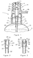
Figure 2 shows the foam-forming assembly ofFigure 1 in more detail; and -
Figure 3 shows an alternative embodiment of a foam-forming assembly arranged on an inlet of a pump. -
Figure 1 shows a foam dispensing device according to the invention generally indicated with thereference numeral 1. Thefoam dispensing device 1 comprises a container 2 (InFigure 1 only the top part is shown) holding a quantity of foamable liquid 3. In thecontainer 2 an opening is provided on which adispensing assembly 4 is mounted. - The
dispensing assembly 4 comprises a bellows type pump 5 having aninlet 6, apump chamber 7 and anoutlet 8. In theinlet 6 aninlet valve 9 is provided, and in theoutlet 8 anoutlet valve 10 is provided. Thetop portion 11 of the bellows pump 5 serves as actuation button and can be actuated manually and reciprocally in vertical direction by pressing the top portion downwards. The cylindrical bellowsside 12 is designed to bias thetop portion 11 back in the top position as shown inFigure 1 , when no downwards pressure is exerted on thetop portion 11. This biasing may be provided by the elasticity of the bellows material itself or may be provided by a spring, for instance embedded in the bellows material. - The
inlet 6 of the pump 5 is connected to a top side of a foam-formingdevice 14. The bottom side of the foam-formingdevice 14 is connected to adip tube 15. The foam-forming device and thedip tube 15 define achannel 16 which runs from a bottom portion of the interior of thecontainer 2 to theinlet 6 of the pump 5. - In an alternative embodiment the dip tube may be an integral part of the foam-forming
device 14. A separate dip tube has the advantage that the foam-formingdevice 14 can easily be adapted for different kinds of containers by providing dip tubes with different shapes and/or heights. In another embodiment, the dip tube may be integral with the foam-forming device, and optionally a dip tube of suitable length may be connected to the dip tube to adapt the height of thechannel 16 to the container. - The foam-forming
device 14 defines an air inlet opening 17 which provides an air path between thechannel 16 and an air containing top portion of the interior of thecontainer 2. - When the top portion of the bellows pump 5 is pressed downwards the volume of the
pump chamber 7 is decreased. As no liquid is present in thepump chamber 7, no liquid or foam will be dispensed. - When the bellows pump 5 is released, liquid 3 will be drawn from the
container 2 through thechannel 16 into thepump chamber 7. While liquid is being sucked up from thecontainer 2, simultaneously air will be drawn through the air inlet opening 17 into the liquid flow in thechannel 16. As a result, a mixture of liquid and air is drawn into thepump chamber 7. Due to the drawing of the mixture of liquid and air into thepump chamber 7, in particular due to the turbulence in the flow, a foam may already come into existence. - When the
top portion 11 is again in the top position, a liquid-air mixture/foam is present in thepump chamber 7. In a next compression stroke of the bellows pump 5, the liquid-air mixture will be (further) formed into a foam which is dispensed through theoutlet 8 and the dispensingopening 18. - When
top portion 11 is released the bellows pump will again be urged to the decompressed top position therewith again drawing liquid and air into thepump chamber 7 which can be dispensed in the form of a foam by further actuation of the bellows pump 5. - In the pump chamber 7 a
sponge 19 is arranged, which is for instance made of a closed or open cell foam material. Any other sponge-like material may also be applied. Thissponge 19 is compressible and may contain a quantity of liquid-air mixture. Thesponge 19 is sized in such a way that during the compressing stroke of the bellows pump 5, thesponge 19 is compressed, and during the upwards movement thesponge 19 may decompress to substantially its original size. This compressing and decompressing of thesponge 19 improves substantially the.quality of the foam dispensed by thefoam dispensing device 1. - As an alternative or in addition to the sponge or sponge-
like material 19 other devices improving the forming of foam such as sieves or porous material in the dispensing path, for instance in the dispensingopening 18 may be provided - When the
dispensing device 1 is not used for a certain time, liquid in thechannel 16 will have the tendency to run back into thecontainer 2, in particular since air may enter thechannel 16 through theair inlet opening 17. When the dispensing device is actuated, first liquid has to be pumped into the channel before foam can be dispensed by the dispensing device. This will require at least one extra, but in practice often more than one actuation stroke before foam is actually dispensed. It has shown that users find these extra strokes for dispensing a foam a significant disadvantage in the use of a foam dispensing device. - To avoid the running of liquid out of the
channel 16, a one-way valve 20 is provided inchannel 16. This one-way valve 20 allows a liquid flow in the direction of the pump, but does not allow a flow in the opposite direction. Thus, when no liquid is drawn to thepump chamber 7, the one-way valve 20 will close thechannel 16. As a result, it is possible to maintain the liquid column in thechannel 16 avoiding the need of the extra strokes to pump the liquid back into the channel. - In an alternative embodiment the one-
way valve 20 may be provided in the dip tube. The one-way valve 20 may be any passive or active valve which substantially avoids that liquid present in thechannel 16 under the one-way valve 20 will not run back into thecontainer 2. - In
figure 2 the foam-formingdevice 14 is shown in more detail. The foam-formingdevice 14 comprises a tube shapedtop end 21 which can be mounted on or in theinlet 6 of the pump. A tube shapedbottom end 22 of the foam-formingdevice 14 is connected to thedip tube 15. - It is advantageous that the tube shaped
top end 21 of the foam-formingdevice 14 has substantially the same shape as the top end of thedip tube 15, and/or that the tube shapedbottom end 22 of the foam-formingdevice 14 of the container has substantially the same shape as theinlet 6 of the pump 5. - In such embodiment the foam-forming
device 14 can simply be placed between theinlet 6 of a liquid pump and the dip tube of said pump therewith transforming a known liquid dispensing device into a foam dispensing device. A known liquid dispensing device suitable for such transformation is for instance disclosed inWO03/035274 A1 - When actually transforming a known liquid dispensing device into a foam-forming device, the
dip tube 15 of the known dispensing device may be too long for the dispensing device due to the height of the foam-forming device. In such case thedip tube 15 may be shortened or replaced by another one. Also a dip tube may be integrally provided on the foam-formingdevice 14. - The foam-forming
device 14 further comprises a number ofgrooves 23. The presence of thegrooves 23 in the foam-formingdevice 14 define when the foam-formingdevice 14 is placed on theinlet 6 of the pump 5 the one or moreair inlet openings 17 required for the provision of air into the liquid flow. - In an alternative embodiment through-going holes may be provided in the foam-forming
device 14 running from theouter surface 24 of the foam-forming device to thechannel 16 at least partially defined by theinner surface 25 of the foam-formingdevice 14. Also, air inlet conduits may be provided which run from thechannel 16 to the environment outside the dispensing device. Such air inlet conduits may be advantageous in the case the container is a compressible container which is not aerated, or any other type of container which does not comprise air. Such containers are for instance used for liquids which easily oxidize or are easily contaminated. - It may be advantageous to provide more than one
air inlet openings 17 in thechannel 16 as this may substantially improve the forming of foam in the air-liquid mixture flow. Furthermore, it is desirable to make theair inlet openings 17 relatively small. In view of this it may be advantageous to provide grooves on the inner surface of the foam-formingdevice 14 to provide theair inlet openings 17 instead of through-going openings, as grooves may be more easily and accurately manufactured. In the embodiment ofFigures 1 and 2 three vertical grooves 23 (only two shown) are provided in the foam-forming device, the grooves being equidistantly being arranged on the cylindricalinner surface 25 of the foam-formingdevice 14. Thesegrooves 23 provide when mounted on theinlet 6 theair inlet openings 17. More than three grooves may be provided to obtain a plurality of air inlet openings about the circumference of thechannel 16. - Preferably, the transverse dimension of the
air inlet openings 17 is not greater than about 1 mm, more preferably smaller than 0,25 mm. - In an alternative embodiment grooves may be provided on the
inlet 6 or both theinlet 6 and the foam-formingdevice 14 to provide theair inlet openings 17 for forming a foam. - In another alternative embodiment of a foam-forming device according to the invention the air inlet openings may be formed as generally described in
WO 91/01259 figure 3 . - This foam-forming device.30 comprises an
end surface 31 which is provided withgrooves 32. Theend surface 31 abuts, when mounted on theinlet 6 of a liquid pump, against anend surface 33 of theinlet 6 of the liquid pump. Thegrooves 32 and theend surface 33 definehorizontal air channels 34. The foam-forming device further comprises acylindrical shoulder 35 which is at the inside also provided withvertical grooves 36. The.outer surface of theinlet 6 and thevertical grooves 36 definevertical air channels 37 connected to thehorizontal air channels 34. Thehorizontal air channels 34 andvertical air channels 37 form a channel to the air inlet openings to introduce air into the liquid flow when liquid is pumped by the liquid pump. - As can been seen in
Figure 3 the foam-formingdevice 30 comprises a plurality of horizontal and vertical.grooves to provide a plurality of air inlet openings distributed evenly about the circumference of thechannel 16. - In alternative embodiments only the horizontal grooves may be provided. In general, the dispensing device comprises two parts having abutting end surfaces, at least one of said end surfaces being provided with grooves to define air channels as air inlet openings. The two parts may both be part of the foam-forming device, or for example one part may be part of the foam-forming device and the other part may be the inlet of a pump as shown in
Figure 3 . - At the bottom side of the foam-forming device an
opening 38 is provided in which adip tube 15 is arranged. Aball 39 is held in this opening above thedip tube 15. The upper inside rim of the dip tube forms aseat 40 for the ball. The combination ofball 39 andseat 40 provides a one-way valve. Other embodiments of the one-way valve may also be applied.
Claims (14)
- A foam-forming device (14) mountable on or in an inlet (6) of a liquid pump, defining at least a part of a liquid supply channel (16), said foam forming device further comprising a one-way valve (20) and defining at least partially an air inlet opening (17), said air inlet opening being provided between said inlet (6) and said one-way valve (20).
- A dispensing device (1) for dispensing a foam, comprising:- a container (2) for holding a liquid (3) having an opening, and- a dispensing assembly (4) mountable on or in said opening, said dispensing assembly comprising:characterized in that, the dispensing device (1) comprises a foam-forming device (14) as claimed in claim 1, mounted on or in the pump inlet and defining at least a part of said channel (16) and defining at least partially said air inlet opening (17).- a pump (5) having a pump chamber (7) and a pump inlet (6) comprising a inlet valve (9) and a pump outlet (8) comprising an outlet valve (10), and- a liquid supply channel (16), one end of said channel being in fluid communication with said inlet, the other end being arranged in a bottom portion of said container,
- Dispensing device as claimed in claim 2, wherein said foam-forming device (14) comprises said one-way valve (20).
- Dispensing device as claimed in claim 2 or 3, wherein said dispensing assembly (4) comprises a dip tube (15) defining at least a part of said channel (16), and wherein said one-way valve (20) is preferably arranged in said dip tube.
- Dispensing device as claimed in any of the claims 2-4, wherein said dispensing assembly (4) comprises a dip tube (15) defining at least a part of said channel (16), and wherein said foam-forming device (14) is arranged between said pump inlet (6) and said dip tube (15).
- Dispensing device as claimed in any of the claims 2-5, wherein said pump inlet (6) comprises a tube shaped end comprising an inlet opening, the foam-forming device (14) having a tube shaped top end to be arranged on or in said tube shaped end of said inlet, and wherein said tube shaped end of said inlet (6) and/or said tube shaped top end of said foam-forming device (14) preferably comprises one or more grooves (23) which define said air inlet opening (17).
- Dispensing device as claimed in claim 6, wherein said foam-forming device (14) comprises a tube shaped bottom end, wherein said one end of said dip tube (15) is or is to be arranged on or in said tube shaped bottom end of said foam-forming device (14).
- Dispensing device as claimed in any of the claims 2-7, wherein said air inlet opening (17) is in fluid communication with a top portion of the interior of said container (2).
- Dispensing device as claimed in any of the claims 2-8, wherein a sponge or sponge-like material (19) is arranged in said pump chamber (7).
- Dispensing device as claimed in any of the claims 2-9, wherein said one-way valve (20) is arranged at or above half the height of said channel (16), preferably at or above 75% of the height of said channel (16).
- Dispensing device as claimed in any of the claims 2-10, wherein two or more air inlet openings (17) are provided between said inlet valve (9) and said one-way valve (20).
- Dispensing device as claimed in any of the claims 2-11, wherein two or more air inlet openings (17) are provided in said channel (16).
- Method for providing a foam dispensing device (1), comprising the steps of:- providing a liquid dispensing device having:characterized by arranging a foam-forming device (14) on or in said inlet (6) of said pump (5), said foam-forming device defining at least a part of a liquid supply channel (16), said foam forming assembly comprising a one-way valve (20) and defining at least partially an air inlet opening (17), said air inlet opening being provided between said inlet valve (9) and said one-way valve (20).- a container (2) for holding a foamable liquid (3) having an opening, and- a dispensing assembly (4) mounted or to be mounted on or in said opening,comprising a pump (5) having a pump chamber (7) and an inlet (6) comprising an inlet valve (9) and an outlet (8) comprising an outlet valve (10),
- The method of claim 13, wherein the method further comprises- arranging a dip tube (15) in said dispensing device (1), one end of said dip tube being in fluid communication with said foam-forming device (14), the other end being arranged in a bottom portion of said container (2).
Applications Claiming Priority (1)
| Application Number | Priority Date | Filing Date | Title |
|---|---|---|---|
| PCT/NL2007/000110 WO2008133491A1 (en) | 2007-04-26 | 2007-04-26 | Dispensing device |
Publications (2)
| Publication Number | Publication Date |
|---|---|
| EP2139607A1 EP2139607A1 (en) | 2010-01-06 |
| EP2139607B1 true EP2139607B1 (en) | 2014-02-12 |
Family
ID=38669785
Family Applications (1)
| Application Number | Title | Priority Date | Filing Date |
|---|---|---|---|
| EP07747292.6A Not-in-force EP2139607B1 (en) | 2007-04-26 | 2007-04-26 | Dispensing device |
Country Status (4)
| Country | Link |
|---|---|
| US (1) | US8356732B2 (en) |
| EP (1) | EP2139607B1 (en) |
| ES (1) | ES2460971T3 (en) |
| WO (1) | WO2008133491A1 (en) |
Cited By (2)
| Publication number | Priority date | Publication date | Assignee | Title |
|---|---|---|---|---|
| US10225885B2 (en) | 2014-04-17 | 2019-03-05 | S. C. Johnson & Son, Inc. | Electrical barrier for wax warmer |
| US10616954B2 (en) | 2014-04-17 | 2020-04-07 | S. C. Johnson & Son, Inc. | Electrical barrier for wax warmer |
Families Citing this family (17)
| Publication number | Priority date | Publication date | Assignee | Title |
|---|---|---|---|---|
| US9271604B2 (en) | 2008-11-10 | 2016-03-01 | Automatic Bar Controls, Inc. | Manifold system for beverage dispenser |
| US9622615B2 (en) | 2008-11-10 | 2017-04-18 | Automatic Bar Controls, Inc. | Touch screen interface for a beverage dispensing machine |
| US8113389B2 (en) * | 2008-12-08 | 2012-02-14 | Kimberly-Clark Worldwide, Inc. | Anti drip fluid dispenser |
| US8616414B2 (en) * | 2009-02-09 | 2013-12-31 | Gojo Industries, Inc. | Bellows foam dispenser |
| WO2011112875A2 (en) | 2010-03-10 | 2011-09-15 | Nuvo Research Inc. | Foamable formulation |
| FR2960166B1 (en) * | 2010-05-18 | 2014-07-11 | Gerard Sannier | DEVICE FOR PRODUCING FOAM CREAM |
| US10442671B2 (en) | 2011-08-29 | 2019-10-15 | Automatic Bar Controls, Inc. | Nozzle with isolation porting |
| US8875952B2 (en) | 2012-03-12 | 2014-11-04 | Gojo Industries, Inc. | Air-activated sequenced valve split foam pump |
| GB201509828D0 (en) | 2015-06-05 | 2015-07-22 | Rieke Packaging Systems Ltd | Foam dispensers |
| CN105083730B (en) * | 2015-06-26 | 2017-07-14 | 钟竞铮 | Elastomeric bladder foam pump |
| RU2682347C1 (en) | 2016-02-12 | 2019-03-19 | Отомэтик Бар Контролз, Инк. | Dispensing head with insulated holes |
| US9919327B2 (en) * | 2016-06-21 | 2018-03-20 | Avon Products, Inc. | Living hinge actuator |
| US10144024B1 (en) * | 2017-06-01 | 2018-12-04 | Yuanhong MEI | Single-hand pressed foam pump head and container thereof |
| WO2019089752A1 (en) * | 2017-11-06 | 2019-05-09 | Gojo Industries, Inc. | Double inlet valve for enhanced pump efficiency |
| KR102414415B1 (en) * | 2020-09-11 | 2022-06-29 | 주식회사 케이알 | Elastic member and pump assembly including the same |
| CN118660765A (en) | 2021-11-19 | 2024-09-17 | 里克包装系统有限公司 | Single polymer reciprocating dispenser for foam products |
| WO2023094337A1 (en) | 2021-11-19 | 2023-06-01 | Rieke Packaging Systems Limited | Integral locking mechanism for reciprocating pumps |
Family Cites Families (13)
| Publication number | Priority date | Publication date | Assignee | Title |
|---|---|---|---|---|
| GB821793A (en) | 1957-11-26 | 1959-10-14 | Ernst Stossel | Foam producing and dispensing device |
| JPS5620052Y2 (en) * | 1975-07-21 | 1981-05-13 | ||
| ATE49716T1 (en) * | 1985-01-28 | 1990-02-15 | Earl Wright Co | FOAM GENERATOR. |
| JPS62282663A (en) * | 1986-05-30 | 1987-12-08 | Takeuchi Press Kogyo Kk | Foamed substance spouting vessel |
| JPH0615891Y2 (en) | 1986-10-31 | 1994-04-27 | 高圧化工株式会社 | Effervescent liquid dispensing container |
| JPH022886A (en) * | 1988-03-03 | 1990-01-08 | Atsuko Kagawa | Spray device |
| JPH0330004A (en) * | 1989-06-28 | 1991-02-08 | Omron Corp | Thermo-hygrostat |
| NL8901877A (en) | 1989-07-20 | 1991-02-18 | Airspray Int Bv | MIXING CHAMBER FOR MIXING A GASEOUS AND LIQUID COMPONENT, METHOD FOR FORMING TIGHT CHANNELS, AND BODY OR ARTICLE ACCORDING THAT METHOD. |
| KR920703410A (en) | 1990-11-07 | 1992-12-17 | 야마구찌 히사기찌 | Foam jet pump vessel |
| JPH0786024B2 (en) * | 1991-12-17 | 1995-09-20 | 誠一 北林 | Foam pump |
| JP2887441B2 (en) * | 1994-06-15 | 1999-04-26 | 株式会社イナックス | Mousse-like soap supply device |
| JPH0811921A (en) * | 1994-06-23 | 1996-01-16 | Yoshino Kogyosho Co Ltd | Foam jet container |
| GB0125702D0 (en) | 2001-10-26 | 2001-12-19 | Scopenext Ltd | Dispenser pump |
-
2007
- 2007-04-26 EP EP07747292.6A patent/EP2139607B1/en not_active Not-in-force
- 2007-04-26 WO PCT/NL2007/000110 patent/WO2008133491A1/en not_active Ceased
- 2007-04-26 US US12/597,244 patent/US8356732B2/en not_active Expired - Fee Related
- 2007-04-26 ES ES07747292.6T patent/ES2460971T3/en active Active
Cited By (2)
| Publication number | Priority date | Publication date | Assignee | Title |
|---|---|---|---|---|
| US10225885B2 (en) | 2014-04-17 | 2019-03-05 | S. C. Johnson & Son, Inc. | Electrical barrier for wax warmer |
| US10616954B2 (en) | 2014-04-17 | 2020-04-07 | S. C. Johnson & Son, Inc. | Electrical barrier for wax warmer |
Also Published As
| Publication number | Publication date |
|---|---|
| US20100133300A1 (en) | 2010-06-03 |
| US8356732B2 (en) | 2013-01-22 |
| WO2008133491A1 (en) | 2008-11-06 |
| ES2460971T3 (en) | 2014-05-16 |
| EP2139607A1 (en) | 2010-01-06 |
Similar Documents
| Publication | Publication Date | Title |
|---|---|---|
| EP2139607B1 (en) | Dispensing device | |
| KR101488526B1 (en) | Foam soap dispenser with stationary dispensing tube | |
| US9072412B2 (en) | Pull actuated foam pump | |
| JP5562852B2 (en) | Foam dispensing device | |
| AU2014209540B2 (en) | Pumps with container vents | |
| CN103118797B (en) | Foam pump | |
| AU2010277425B2 (en) | Foam pump | |
| US8591207B2 (en) | Pump with side inlet valve for improved functioning in an inverted container | |
| US20170181584A1 (en) | Vented refill units and dispensers having vented refill units | |
| EP2209558B1 (en) | Device for dispensing fluid | |
| JP2008237904A5 (en) | ||
| JP2004522562A (en) | Form generator | |
| CN104755178A (en) | Horizontal pumps, refill units and foam dispensers | |
| US20090194563A1 (en) | Foot Operated Foaming Soap Dispenser | |
| US20090057345A1 (en) | Fluid dispenser | |
| CN201316695Y (en) | Foam type spray head structure | |
| JP2006312474A (en) | Pump type foam discharge container | |
| HK1143776B (en) | Device for dispensing fluid |
Legal Events
| Date | Code | Title | Description |
|---|---|---|---|
| PUAI | Public reference made under article 153(3) epc to a published international application that has entered the european phase |
Free format text: ORIGINAL CODE: 0009012 |
|
| 17P | Request for examination filed |
Effective date: 20091103 |
|
| AK | Designated contracting states |
Kind code of ref document: A1 Designated state(s): AT BE BG CH CY CZ DE DK EE ES FI FR GB GR HU IE IS IT LI LT LU LV MC MT NL PL PT RO SE SI SK TR |
|
| DAX | Request for extension of the european patent (deleted) | ||
| 17Q | First examination report despatched |
Effective date: 20100921 |
|
| GRAP | Despatch of communication of intention to grant a patent |
Free format text: ORIGINAL CODE: EPIDOSNIGR1 |
|
| GRAS | Grant fee paid |
Free format text: ORIGINAL CODE: EPIDOSNIGR3 |
|
| GRAP | Despatch of communication of intention to grant a patent |
Free format text: ORIGINAL CODE: EPIDOSNIGR1 |
|
| INTG | Intention to grant announced |
Effective date: 20130906 |
|
| GRAA | (expected) grant |
Free format text: ORIGINAL CODE: 0009210 |
|
| AK | Designated contracting states |
Kind code of ref document: B1 Designated state(s): AT BE BG CH CY CZ DE DK EE ES FI FR GB GR HU IE IS IT LI LT LU LV MC MT NL PL PT RO SE SI SK TR |
|
| REG | Reference to a national code |
Ref country code: GB Ref legal event code: FG4D |
|
| REG | Reference to a national code |
Ref country code: CH Ref legal event code: EP |
|
| REG | Reference to a national code |
Ref country code: AT Ref legal event code: REF Ref document number: 651889 Country of ref document: AT Kind code of ref document: T Effective date: 20140215 |
|
| REG | Reference to a national code |
Ref country code: IE Ref legal event code: FG4D |
|
| REG | Reference to a national code |
Ref country code: DE Ref legal event code: R096 Ref document number: 602007035058 Country of ref document: DE Effective date: 20140327 |
|
| REG | Reference to a national code |
Ref country code: NL Ref legal event code: T3 |
|
| REG | Reference to a national code |
Ref country code: ES Ref legal event code: FG2A Ref document number: 2460971 Country of ref document: ES Kind code of ref document: T3 Effective date: 20140516 |
|
| REG | Reference to a national code |
Ref country code: AT Ref legal event code: MK05 Ref document number: 651889 Country of ref document: AT Kind code of ref document: T Effective date: 20140212 |
|
| REG | Reference to a national code |
Ref country code: LT Ref legal event code: MG4D |
|
| PG25 | Lapsed in a contracting state [announced via postgrant information from national office to epo] |
Ref country code: IS Free format text: LAPSE BECAUSE OF FAILURE TO SUBMIT A TRANSLATION OF THE DESCRIPTION OR TO PAY THE FEE WITHIN THE PRESCRIBED TIME-LIMIT Effective date: 20140612 Ref country code: LT Free format text: LAPSE BECAUSE OF FAILURE TO SUBMIT A TRANSLATION OF THE DESCRIPTION OR TO PAY THE FEE WITHIN THE PRESCRIBED TIME-LIMIT Effective date: 20140212 |
|
| PGFP | Annual fee paid to national office [announced via postgrant information from national office to epo] |
Ref country code: GB Payment date: 20140422 Year of fee payment: 8 |
|
| PG25 | Lapsed in a contracting state [announced via postgrant information from national office to epo] |
Ref country code: FI Free format text: LAPSE BECAUSE OF FAILURE TO SUBMIT A TRANSLATION OF THE DESCRIPTION OR TO PAY THE FEE WITHIN THE PRESCRIBED TIME-LIMIT Effective date: 20140212 Ref country code: CY Free format text: LAPSE BECAUSE OF FAILURE TO SUBMIT A TRANSLATION OF THE DESCRIPTION OR TO PAY THE FEE WITHIN THE PRESCRIBED TIME-LIMIT Effective date: 20140212 Ref country code: SE Free format text: LAPSE BECAUSE OF FAILURE TO SUBMIT A TRANSLATION OF THE DESCRIPTION OR TO PAY THE FEE WITHIN THE PRESCRIBED TIME-LIMIT Effective date: 20140212 Ref country code: PT Free format text: LAPSE BECAUSE OF FAILURE TO SUBMIT A TRANSLATION OF THE DESCRIPTION OR TO PAY THE FEE WITHIN THE PRESCRIBED TIME-LIMIT Effective date: 20140612 Ref country code: AT Free format text: LAPSE BECAUSE OF FAILURE TO SUBMIT A TRANSLATION OF THE DESCRIPTION OR TO PAY THE FEE WITHIN THE PRESCRIBED TIME-LIMIT Effective date: 20140212 |
|
| PGFP | Annual fee paid to national office [announced via postgrant information from national office to epo] |
Ref country code: NL Payment date: 20140418 Year of fee payment: 8 |
|
| PG25 | Lapsed in a contracting state [announced via postgrant information from national office to epo] |
Ref country code: BE Free format text: LAPSE BECAUSE OF FAILURE TO SUBMIT A TRANSLATION OF THE DESCRIPTION OR TO PAY THE FEE WITHIN THE PRESCRIBED TIME-LIMIT Effective date: 20140212 Ref country code: LV Free format text: LAPSE BECAUSE OF FAILURE TO SUBMIT A TRANSLATION OF THE DESCRIPTION OR TO PAY THE FEE WITHIN THE PRESCRIBED TIME-LIMIT Effective date: 20140212 |
|
| PG25 | Lapsed in a contracting state [announced via postgrant information from national office to epo] |
Ref country code: DK Free format text: LAPSE BECAUSE OF FAILURE TO SUBMIT A TRANSLATION OF THE DESCRIPTION OR TO PAY THE FEE WITHIN THE PRESCRIBED TIME-LIMIT Effective date: 20140212 Ref country code: RO Free format text: LAPSE BECAUSE OF FAILURE TO SUBMIT A TRANSLATION OF THE DESCRIPTION OR TO PAY THE FEE WITHIN THE PRESCRIBED TIME-LIMIT Effective date: 20140212 Ref country code: EE Free format text: LAPSE BECAUSE OF FAILURE TO SUBMIT A TRANSLATION OF THE DESCRIPTION OR TO PAY THE FEE WITHIN THE PRESCRIBED TIME-LIMIT Effective date: 20140212 Ref country code: CZ Free format text: LAPSE BECAUSE OF FAILURE TO SUBMIT A TRANSLATION OF THE DESCRIPTION OR TO PAY THE FEE WITHIN THE PRESCRIBED TIME-LIMIT Effective date: 20140212 |
|
| REG | Reference to a national code |
Ref country code: DE Ref legal event code: R097 Ref document number: 602007035058 Country of ref document: DE |
|
| PG25 | Lapsed in a contracting state [announced via postgrant information from national office to epo] |
Ref country code: SK Free format text: LAPSE BECAUSE OF FAILURE TO SUBMIT A TRANSLATION OF THE DESCRIPTION OR TO PAY THE FEE WITHIN THE PRESCRIBED TIME-LIMIT Effective date: 20140212 Ref country code: LU Free format text: LAPSE BECAUSE OF FAILURE TO SUBMIT A TRANSLATION OF THE DESCRIPTION OR TO PAY THE FEE WITHIN THE PRESCRIBED TIME-LIMIT Effective date: 20140426 Ref country code: PL Free format text: LAPSE BECAUSE OF FAILURE TO SUBMIT A TRANSLATION OF THE DESCRIPTION OR TO PAY THE FEE WITHIN THE PRESCRIBED TIME-LIMIT Effective date: 20140212 Ref country code: MC Free format text: LAPSE BECAUSE OF FAILURE TO SUBMIT A TRANSLATION OF THE DESCRIPTION OR TO PAY THE FEE WITHIN THE PRESCRIBED TIME-LIMIT Effective date: 20140212 |
|
| REG | Reference to a national code |
Ref country code: CH Ref legal event code: PL |
|
| PLBE | No opposition filed within time limit |
Free format text: ORIGINAL CODE: 0009261 |
|
| STAA | Information on the status of an ep patent application or granted ep patent |
Free format text: STATUS: NO OPPOSITION FILED WITHIN TIME LIMIT |
|
| 26N | No opposition filed |
Effective date: 20141113 |
|
| REG | Reference to a national code |
Ref country code: IE Ref legal event code: MM4A |
|
| PG25 | Lapsed in a contracting state [announced via postgrant information from national office to epo] |
Ref country code: LI Free format text: LAPSE BECAUSE OF NON-PAYMENT OF DUE FEES Effective date: 20140430 Ref country code: CH Free format text: LAPSE BECAUSE OF NON-PAYMENT OF DUE FEES Effective date: 20140430 |
|
| REG | Reference to a national code |
Ref country code: DE Ref legal event code: R097 Ref document number: 602007035058 Country of ref document: DE Effective date: 20141113 |
|
| REG | Reference to a national code |
Ref country code: FR Ref legal event code: PLFP Year of fee payment: 9 |
|
| PG25 | Lapsed in a contracting state [announced via postgrant information from national office to epo] |
Ref country code: IE Free format text: LAPSE BECAUSE OF NON-PAYMENT OF DUE FEES Effective date: 20140426 |
|
| PG25 | Lapsed in a contracting state [announced via postgrant information from national office to epo] |
Ref country code: SI Free format text: LAPSE BECAUSE OF FAILURE TO SUBMIT A TRANSLATION OF THE DESCRIPTION OR TO PAY THE FEE WITHIN THE PRESCRIBED TIME-LIMIT Effective date: 20140212 |
|
| GBPC | Gb: european patent ceased through non-payment of renewal fee |
Effective date: 20150426 |
|
| REG | Reference to a national code |
Ref country code: NL Ref legal event code: MM Effective date: 20150501 |
|
| PG25 | Lapsed in a contracting state [announced via postgrant information from national office to epo] |
Ref country code: GB Free format text: LAPSE BECAUSE OF NON-PAYMENT OF DUE FEES Effective date: 20150426 |
|
| PG25 | Lapsed in a contracting state [announced via postgrant information from national office to epo] |
Ref country code: MT Free format text: LAPSE BECAUSE OF FAILURE TO SUBMIT A TRANSLATION OF THE DESCRIPTION OR TO PAY THE FEE WITHIN THE PRESCRIBED TIME-LIMIT Effective date: 20140212 Ref country code: NL Free format text: LAPSE BECAUSE OF NON-PAYMENT OF DUE FEES Effective date: 20150501 |
|
| REG | Reference to a national code |
Ref country code: FR Ref legal event code: PLFP Year of fee payment: 10 |
|
| PG25 | Lapsed in a contracting state [announced via postgrant information from national office to epo] |
Ref country code: BG Free format text: LAPSE BECAUSE OF FAILURE TO SUBMIT A TRANSLATION OF THE DESCRIPTION OR TO PAY THE FEE WITHIN THE PRESCRIBED TIME-LIMIT Effective date: 20140212 |
|
| PG25 | Lapsed in a contracting state [announced via postgrant information from national office to epo] |
Ref country code: GR Free format text: LAPSE BECAUSE OF FAILURE TO SUBMIT A TRANSLATION OF THE DESCRIPTION OR TO PAY THE FEE WITHIN THE PRESCRIBED TIME-LIMIT Effective date: 20140513 |
|
| PG25 | Lapsed in a contracting state [announced via postgrant information from national office to epo] |
Ref country code: HU Free format text: LAPSE BECAUSE OF FAILURE TO SUBMIT A TRANSLATION OF THE DESCRIPTION OR TO PAY THE FEE WITHIN THE PRESCRIBED TIME-LIMIT; INVALID AB INITIO Effective date: 20070426 Ref country code: TR Free format text: LAPSE BECAUSE OF FAILURE TO SUBMIT A TRANSLATION OF THE DESCRIPTION OR TO PAY THE FEE WITHIN THE PRESCRIBED TIME-LIMIT Effective date: 20140212 |
|
| REG | Reference to a national code |
Ref country code: FR Ref legal event code: PLFP Year of fee payment: 11 |
|
| REG | Reference to a national code |
Ref country code: FR Ref legal event code: PLFP Year of fee payment: 12 |
|
| PGFP | Annual fee paid to national office [announced via postgrant information from national office to epo] |
Ref country code: DE Payment date: 20180427 Year of fee payment: 12 Ref country code: ES Payment date: 20180503 Year of fee payment: 12 |
|
| PGFP | Annual fee paid to national office [announced via postgrant information from national office to epo] |
Ref country code: IT Payment date: 20180423 Year of fee payment: 12 Ref country code: FR Payment date: 20180425 Year of fee payment: 12 |
|
| REG | Reference to a national code |
Ref country code: DE Ref legal event code: R119 Ref document number: 602007035058 Country of ref document: DE |
|
| PG25 | Lapsed in a contracting state [announced via postgrant information from national office to epo] |
Ref country code: DE Free format text: LAPSE BECAUSE OF NON-PAYMENT OF DUE FEES Effective date: 20191101 |
|
| PG25 | Lapsed in a contracting state [announced via postgrant information from national office to epo] |
Ref country code: FR Free format text: LAPSE BECAUSE OF NON-PAYMENT OF DUE FEES Effective date: 20190430 |
|
| PG25 | Lapsed in a contracting state [announced via postgrant information from national office to epo] |
Ref country code: IT Free format text: LAPSE BECAUSE OF NON-PAYMENT OF DUE FEES Effective date: 20190426 |
|
| REG | Reference to a national code |
Ref country code: ES Ref legal event code: FD2A Effective date: 20200901 |
|
| PG25 | Lapsed in a contracting state [announced via postgrant information from national office to epo] |
Ref country code: ES Free format text: LAPSE BECAUSE OF NON-PAYMENT OF DUE FEES Effective date: 20190427 |