EP2139528B1 - Container for sterilisation indicator - Google Patents
Container for sterilisation indicator Download PDFInfo
- Publication number
- EP2139528B1 EP2139528B1 EP08744899A EP08744899A EP2139528B1 EP 2139528 B1 EP2139528 B1 EP 2139528B1 EP 08744899 A EP08744899 A EP 08744899A EP 08744899 A EP08744899 A EP 08744899A EP 2139528 B1 EP2139528 B1 EP 2139528B1
- Authority
- EP
- European Patent Office
- Prior art keywords
- layer
- challenge device
- process challenge
- chamber
- pcd
- Prior art date
- Legal status (The legal status is an assumption and is not a legal conclusion. Google has not performed a legal analysis and makes no representation as to the accuracy of the status listed.)
- Active
Links
Images



Classifications
-
- A—HUMAN NECESSITIES
- A61—MEDICAL OR VETERINARY SCIENCE; HYGIENE
- A61L—METHODS OR APPARATUS FOR STERILISING MATERIALS OR OBJECTS IN GENERAL; DISINFECTION, STERILISATION OR DEODORISATION OF AIR; CHEMICAL ASPECTS OF BANDAGES, DRESSINGS, ABSORBENT PADS OR SURGICAL ARTICLES; MATERIALS FOR BANDAGES, DRESSINGS, ABSORBENT PADS OR SURGICAL ARTICLES
- A61L2/00—Disinfection or sterilisation of materials or objects, in general; Accessories therefor
- A61L2/26—Accessories
- A61L2/28—Devices for testing the effectiveness or completeness of sterilisation or disinfection, e.g. indicators which change colour
-
- A—HUMAN NECESSITIES
- A61—MEDICAL OR VETERINARY SCIENCE; HYGIENE
- A61L—METHODS OR APPARATUS FOR STERILISING MATERIALS OR OBJECTS IN GENERAL; DISINFECTION, STERILISATION OR DEODORISATION OF AIR; CHEMICAL ASPECTS OF BANDAGES, DRESSINGS, ABSORBENT PADS OR SURGICAL ARTICLES; MATERIALS FOR BANDAGES, DRESSINGS, ABSORBENT PADS OR SURGICAL ARTICLES
- A61L2/00—Disinfection or sterilisation of materials or objects, in general; Accessories therefor
- A61L2/16—Disinfection or sterilisation of materials or objects, in general; Accessories therefor using chemical substances
- A61L2/20—Gaseous substances, e.g. vapours
- A61L2/208—Hydrogen peroxide
Definitions
- the present invention relates generally to monitoring of a biocontamination deactivation process, and more particularly to a process challenge device for assessing the effective performance of a biocontamination deactivation process.
- DE 10 2004 040733 A1 discloses a system having two casing parts which coordinate with each other and a guiding trench which is introduced into one and/or both casing parts for feeding a washing and cleaning medium.
- the guiding trench collects the test dirt and/or contamination.
- a connection is provided on a side of the guiding trench and connects with the medium feed of the machine via an interface.
- US 4353990A discloses a device for monitoring thermal energy input and displaying the relationship of the thermal energy input to a selected time/temperature relationship.
- the device employs an indicating material which, when melted, expands and flows into a narrow channel to provide an irreversible, visible indication of the thermal energy to which the device has been exposed.
- WO99/62569 discloses a sterilization indicator for testing the effectiveness of a sterilization procedure comprises a source of an enzyme, a sterilant-resistant chemical associated with the enzyme, and a substrate that reacts with the enzyme to form a detectable enzyme- modified product that provides an indication of the failure of the sterilization procedure.
- the sterilant-resistant chemical may be a polyglycerol alkyl ester, polyglycerol alkyl ether, an ethoxylated polyhydric alcohol ester, or a polyhydric alcohol ether.
- the indicator may be used to test the effectiveness of a hydrogen peroxide plasma sterilization procedure and may be provided with a non-challenge test pack or a lumen-challenge test pack.
- Medical instruments such as dental, pharmaceutical, veterinary, and mortuary devices that are exposed to blood or other bodily fluids require thorough cleaning and microbial deactivation between each use.
- Medical instruments may be microbially deactivated by exposure to a gaseous or vaporous deactivating agent, such as vaporized hydrogen peroxide, during a microbial deactivation process.
- a gaseous or vaporous deactivating agent such as vaporized hydrogen peroxide
- Some surfaces of medical instruments are difficult to expose to the vaporous deactivating agent because of the shape, i.e., geometry, of the instrument. For example, for instruments having lumens, it is difficult to expose the inner surfaces of the lumens to the vaporous deactivating agent. As a result, a microbial deactivation process may not be effective because such surfaces have not been successfully deactivated by appropriate exposure to the vaporous deactivating agent.
- a process challenge device (also commonly referred to as a "test pack”) is designed to simulate an item being deactivated and to constitute a defined challenge to the microbial deactivation process.
- a process challenge device PCD
- a PCD includes a housing and a biological indicator (BI) and/or a chemical indicator (CI), that are placed inside the housing.
- the housing includes internal passageways that create a challenge to the microbial deactivation process that is representative of the most difficult item to deactivate in a load.
- the biological indicator and/or chemical indicator are analyzed in a known manner to determine the effectiveness of the microbial deactivation process.
- a conventional PCD housing includes a narrow internal passageway formed therein that has an open end and a closed end. The open end of the passageway is in fluid communication with a region external to the housing. A BI and/or CI is disposed at the closed end of the passageway. During a microbial deactivation process, vaporized deactivating agent can travel from the region external to the housing, along the passageway, and to the BI and/or CI located at the closed end of the passageway.
- a known PCD housing includes a layer of flexible plastic film that defines a wall of the passageway.
- the flexible plastic film may collapse or be drawn into the passageway when the PCD is exposed to large changes in pressure, thereby reducing the diameter of the passageway.
- a PCD having a passageway with a reduced diameter provides a challenge greater than the most difficult item to deactivate in the load. Accordingly, the BI and/or CI may not provide accurate results.
- vaporous deactivating agent e.g., vaporized hydrogen peroxide
- the BI and/or CI of the PCD may not be exposed to the same concentration of vaporous deactivating agent (e.g., vaporized hydrogen peroxide) as the surfaces of the instruments being deactivated. It is believed that this inconsistency results from inadequate circulation of the vaporous deactivating agent within the PCD housing, as compared to the circulation of vaporous deactivating agent within the item (e.g., a lumened instrument) being deactivated.
- vaporous deactivating agent e.g., vaporized hydrogen peroxide
- the present invention overcomes these and other problems by providing a PCD that maintains a challenge to microbial deactivation that is representative of the most difficult item to deactivate in a load and can provide fluid circulation therein to provide appropriate exposure to a biological and/or chemical indicator.
- a process challenge device for evaluating the effectiveness of a microbial deactivation process in accordance with claim 1.
- Advantageous features are provided in the dependent claims.
- An advantage of the present invention is the provision of a PCD for determining the effectiveness of a deactivation process that uses vaporized hydrogen peroxide to microbially deactivate medical instruments.
- Another advantage of the present invention is the provision of a PCD housing that includes a passageway with two (2) open ends.
- Still another advantage of the present invention is the provision of a PCD housing including a passageway defined therein by walls that are resistant to collapse in response to pressure changes.
- Still another advantage of the present invention is the provision of a PCD housing having a passageway defined therein that is arranged to minimize condensation of a vaporous deactivating agent therein.
- Still another advantage of the present invention is the provision of a PCD housing providing improved circulation of a vaporous deactivating agent therein.
- Yet another advantage of the present invention is the provision of a PCD housing that allows convenient removal of biological and/or chemical indicators from the PCD housing.
- Yet another advantage of the present invention is the provision of a PCD that can be manufactured simply and efficiently.
- FIG. 1 is a perspective view of a PCD, illustrating one embodiment of the present invention
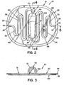
- FIG. 2 is a top plan view of the PCD shown in FIG. 1 ;
- FIG. 3 is a side plan view of the PCD shown in FIG. 1 ;
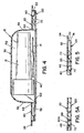
- FIG. 4 is a cross-sectional view of the PCD taken along lines 4-4 of FIG. 2 ;
- FIG. 5 is a cross-sectional view of the PCD taken along lines 5-5 of FIG. 2 ;
- FIG. 5A is a cross-sectional view taken along lines 5-5 of FIG. 2 illustrating an alternative embodiment of the PCD;
- FIG. 6 is an exploded view of the PCD shown in FIG. 1 ;
- FIG. 7 is a perspective view of the PCD showing removal of indicators therefrom.
- FIGS. 1-3 show a process challenge device (PCD) 10 according to one embodiment of the present invention.
- PCD 10 includes a housing 15 and an indicator device, such as a biological indicator (BI) 12 and/or a chemical indicator (CI) 14.
- Housing 15 is generally comprised of a first layer 20 and a second layer 120, as best seen in FIGS. 3 and 6 .
- First layer 20 is a generally planar sheet having a first end 26 and a second end 28.
- a side wall 22 extends from the peripheral edge of first layer 20, and a flange 24 extends outward from side wall 22.
- Side wall 22 and flange 24 provide additional structural rigidity to first layer 20.
- a recess 30, a first channel 40 and a second channel 60 are formed in first layer 20.
- Recess 30 has a first end 32 and a second end 34. In the illustrated embodiment, recess 30 is generally located in the center region of first layer 20. Recess 30 is dimensioned to receive BI 12 and/or CI 14.
- First channel 40 extends between first end 26 of first layer 20 and first end 32 of recess 30. Accordingly, first channel 40 has an outer end 42 located at first end 26 of first layer 20 and an inner end 44 located at first end 32 of recess 30.
- second channel 60 extends between second end 28 of first layer 20 and second end 34 of recess 30. Accordingly, second channel 60 has an outer end 62 located at second end 28 of first layer 20 and an inner end 64 located at second end 34 of recess 30.
- first channel 40 includes generally straight portions 46 and bent portions 48.
- second channel 60 includes generally straight portions 66 and bent portions 68. It should be appreciated that first and second channels 40, 60 can be formed in tortuous shapes other than as shown in the figures.
- second layer 120 is a generally planar sheet having dimensions similar to first layer 20.
- An opening 122 is formed in second layer 120.
- a seal member 140 covers opening 122, as will be described in detail below. It is contemplated that seal member 140 may be made of various different materials, including, but not limited to, a metal foil, a thermoplastic having a metallic layer deposited thereon, or a combination thereof, as well as polypropylene sheeting.
- Second layer 120 is fixed to the lower surface of first layer 20, such that opening 122 generally aligns with recess 30, as best seen in FIG. 6 . It is contemplated that second layer 120 may be fixed to first layer 20 in a variety of different ways, including, but not limited to, ultrasonic welding, solvent welding, an adhesive, or a combination thereof.
- Opening 122 of second layer 120 is dimensioned to allow BI 12 and CI 14 to pass therethrough for insertion and removal from recess 30.
- Seal member 140 covers opening 122 to seal BI 12 and/or CI 14 within recess 30.
- An adhesive is preferably used to attach seal member 140 to second layer 120. Seal member 140 may be punctured, torn or peeled away to allow removal of BI 12 and CI 14 from recess 30 following a microbial deactivation process.
- First layer 20 and second layer 120 are preferably formed of a generally rigid, thermoplastic material, including, but not limited to, polypropylene, polyethylene, polystryrene, and polyvinyl chloride (PVC).
- a generally rigid, thermoplastic material including, but not limited to, polypropylene, polyethylene, polystryrene, and polyvinyl chloride (PVC).
- first layer 20 and second layer 120 may be alternatively formed from a single sheet that is folded to join first layer 20 to second layer 120. In this alternative embodiment, first layer 20 and second layer 120 are joined along a common edge.
- first channel 40 and second layer 120 define a first conduit 52
- second channel 60 and second layer 120 define a second conduit 72, as best seen in FIGS. 1 and 2 .
- Recess 30 of first layer 20, second layer 120, and seal member 140 define a chamber 132 when first layer 20 is fixed to second layer 120.
- First conduit 52 has an open end 54 at one end thereof and is in fluid communication with chamber 132 at the other end thereof.
- second conduit 72 has an open end 74 at one end thereof and is in fluid communication with chamber 132 at the other end thereof.
- first and second conduits 52, 72 each have an inner diameter (ID) in the range of 1 to 2 mm, and each have a total length L in the range of 25 to 50 cm.
- Inner diameter ID and length L are preferably selected to be similar to the dimensions of a lumen of an instrument being deactivated. In the illustrated embodiment the respective lengths L and diameters ID of first conduit 52 and second conduit 72 are substantially the same.
- First conduit 52, second conduit 72 and chamber 132 collectively define a continuous serpentine or tortuous pathway extending between open ends 54 and 74 to allow fluid flow through PCD 10.
- second channel 60A is defined by a plurality of depressions 69 formed in first layer 20.
- first channel (not shown) is defined by a plurality of depressions (not shown) formed in first layer 20.
- First layer 20 is attached to second layer 120 at the plurality of depressions 69.
- first and second channels 40, 60 are defined by second layer 120.
- First and second channels 40, 60 are defined by portions of both first layer 20 and second layer 120.
- BI 12 is a conventional self-contained indicator device that includes a source of viable microorganisms, i.e., a biological challenge, and a source of nutrients.
- the source of nutrients is contained within a vapor impermeable container.
- the source of microorganisms is not exposed to the source of nutrients, unless the vapor impermeable container is opened, i.e., broken.
- the source of viable microorganisms is exposed to vaporous deactivating agent entering recess 30.
- CI 14 is a conventional indicator device comprised of a generally planar sheet that is coated or impregnated with a reactive chemical substance.
- the reactive chemical substance is selected such that a visual indication (e.g., a color change) results from exposure to a vaporous deactivating agent, such as vaporized hydrogen peroxide.
- First layer 20 and second layer 120 are aligned with each other such that recess 30 of first layer 20 is aligned with opening 122 of second layer 120.
- first layer 20 and second layer 120 are fixed to each other by such means as ultrasonic welding, solvent welding, an adhesive, or a combination thereof.
- BI 12 and/or CI 14 are inserted through opening 122 of second layer 120, and placed inside recess 30 of first layer 20.
- Seal member 140 is then placed over opening 122 and fixed to second layer 120, preferably by use of an adhesive.
- a deactivation device e.g., a sterilization system
- a microbial deactivating agent for microbial deactivation e.g., a sterilization system
- the present invention is described herein with reference to a deactivation device that uses vaporized hydrogen peroxide as the deactivating agent.
- the present invention may be used in connection with deactivation devices that use other types of deactivating agents.
- Vaporized hydrogen peroxide is injected into the deactivation chamber during a deactivation process to expose the instrument to vaporized hydrogen peroxide, thereby effecting microbial deactivation.
- Vaporized hydrogen peroxide entering the deactivation chamber also enters first and second conduits 52, 72 of PCD 10 via open ends 54 and 74.
- Vaporized hydrogen peroxide entering first and second conduits 52, 72 flows along a portion of a tortuous pathway to chamber 132, thereby exposing BI 12 and CI 14 to the vaporized hydrogen peroxide.
- the source of viable microorganisms within BI 12 is exposed to the vaporized hydrogen peroxide.
- a vacuum may be drawn within the deactivation chamber in order to evacuate the deactivation chamber.
- the pressure within the deactivation chamber may be reduced to less than 1 Torr.
- PCD 10 is removed from the deactivation chamber.
- Seal member 140 is either removed, punctured or peeled away to allow removal of BI 12 and CI 14 from recess 30, as shown in FIG. 7 .
- CI 14 may be visually inspected while located within recess 30 if first layer 20, second layer 120, and/or seal member 140, are made of a transparent material.
- BI 12 may be activated by breaking the impermeable container or otherwise opening the impermeable container that contains the source of nutrients. In this manner, the microorganisms are exposed to the nutrients. BI 12 is then incubated for an incubation period of predetermined duration. If microorganisms within BI 12 are not deactivated by exposure to vaporized hydrogen peroxide during the deactivation process, the microorganisms will grow during an incubation period. Subsequent examination of BI 12 will determine whether any microorganism growth has occurred. Microorganism growth indicates that the deactivation process was ineffective and that the instruments exposed to the vaporized hydrogen peroxide along with PCD 10 were not effectively deactivated.
- first conduit 52, second conduit 72 and chamber 132 are preferably selected such that PCD 10 simulates a "worst-case" instrument, i.e., an instrument having a geometry that is the most difficult to successfully deactivate by exposure to a vaporous microbial deactivating agent. Therefore, if PCD 10, as a worst-case instrument, is successfully deactivated during a deactivation process, then it follows that the instruments exposed to that same deactivation process were also successfully deactivated. Accordingly, if BI 12 shows no microorganism growth during the incubation period, then all microorganisms within BI 12 were deactivated during the deactivation process. Thus, it can be concluded that the instruments undergoing the same deactivation process have also been successfully deactivated.
- a "worst-case” instrument i.e., an instrument having a geometry that is the most difficult to successfully deactivate by exposure to a vaporous microbial deactivating agent. Therefore, if PCD 10, as a worst-case
Landscapes
- Health & Medical Sciences (AREA)
- Epidemiology (AREA)
- Life Sciences & Earth Sciences (AREA)
- Animal Behavior & Ethology (AREA)
- General Health & Medical Sciences (AREA)
- Public Health (AREA)
- Veterinary Medicine (AREA)
- Apparatus For Disinfection Or Sterilisation (AREA)
- Apparatus Associated With Microorganisms And Enzymes (AREA)
- Investigating Or Analysing Materials By The Use Of Chemical Reactions (AREA)
- Investigating Or Analyzing Non-Biological Materials By The Use Of Chemical Means (AREA)
Description
- The present invention relates generally to monitoring of a biocontamination deactivation process, and more particularly to a process challenge device for assessing the effective performance of a biocontamination deactivation process.
-
DE 10 2004 040733 A1 discloses a system having two casing parts which coordinate with each other and a guiding trench which is introduced into one and/or both casing parts for feeding a washing and cleaning medium. The guiding trench collects the test dirt and/or contamination. A connection is provided on a side of the guiding trench and connects with the medium feed of the machine via an interface. -
US 4353990A discloses a device for monitoring thermal energy input and displaying the relationship of the thermal energy input to a selected time/temperature relationship. The device employs an indicating material which, when melted, expands and flows into a narrow channel to provide an irreversible, visible indication of the thermal energy to which the device has been exposed. -
WO99/62569 - Medical instruments (such as dental, pharmaceutical, veterinary, and mortuary devices) that are exposed to blood or other bodily fluids require thorough cleaning and microbial deactivation between each use. Medical instruments may be microbially deactivated by exposure to a gaseous or vaporous deactivating agent, such as vaporized hydrogen peroxide, during a microbial deactivation process. For a medical instrument to be successfully deactivated during a microbial deactivation process, all surfaces of the medical instrument must be exposed to a predetermined minimum concentration of vaporized hydrogen peroxide for a predetermined minimum period of time.
- Some surfaces of medical instruments are difficult to expose to the vaporous deactivating agent because of the shape, i.e., geometry, of the instrument. For example, for instruments having lumens, it is difficult to expose the inner surfaces of the lumens to the vaporous deactivating agent. As a result, a microbial deactivation process may not be effective because such surfaces have not been successfully deactivated by appropriate exposure to the vaporous deactivating agent.
- A process challenge device (also commonly referred to as a "test pack") is designed to simulate an item being deactivated and to constitute a defined challenge to the microbial deactivation process. In order to assess the effectiveness of a microbial deactivation process a process challenge device (PCD) is placed within a deactivation chamber along with the instruments being deactivated. A PCD includes a housing and a biological indicator (BI) and/or a chemical indicator (CI), that are placed inside the housing. The housing includes internal passageways that create a challenge to the microbial deactivation process that is representative of the most difficult item to deactivate in a load. Following completion of a microbial deactivation process, the biological indicator and/or chemical indicator are analyzed in a known manner to determine the effectiveness of the microbial deactivation process.
- A conventional PCD housing includes a narrow internal passageway formed therein that has an open end and a closed end. The open end of the passageway is in fluid communication with a region external to the housing. A BI and/or CI is disposed at the closed end of the passageway. During a microbial deactivation process, vaporized deactivating agent can travel from the region external to the housing, along the passageway, and to the BI and/or CI located at the closed end of the passageway.
- One problem with existing PCD housings is that the passageway leading to the BI and/or CI can become partially or fully blocked, thereby causing the BI and/or CI to provide inaccurate results concerning the effectiveness of the microbial deactivation process. The passageway within the housing can become blocked as the result of several conditions. For example, condensation of the vaporous deactivating agent within the passageway can result in blockage of the passageway. The passageway can also become blocked when the walls defining the passageway collapse or are drawn into the passageway in response to pressure changes during the microbial deactivation process. For example, a known PCD housing includes a layer of flexible plastic film that defines a wall of the passageway. During a deactivation process, the flexible plastic film may collapse or be drawn into the passageway when the PCD is exposed to large changes in pressure, thereby reducing the diameter of the passageway. A PCD having a passageway with a reduced diameter provides a challenge greater than the most difficult item to deactivate in the load. Accordingly, the BI and/or CI may not provide accurate results.
- Another problem with existing PCD housings is that the BI and/or CI of the PCD may not be exposed to the same concentration of vaporous deactivating agent (e.g., vaporized hydrogen peroxide) as the surfaces of the instruments being deactivated. It is believed that this inconsistency results from inadequate circulation of the vaporous deactivating agent within the PCD housing, as compared to the circulation of vaporous deactivating agent within the item (e.g., a lumened instrument) being deactivated.
- The present invention overcomes these and other problems by providing a PCD that maintains a challenge to microbial deactivation that is representative of the most difficult item to deactivate in a load and can provide fluid circulation therein to provide appropriate exposure to a biological and/or chemical indicator.
- In accordance with one embodiment of the present invention, there is provided a process challenge device for evaluating the effectiveness of a microbial deactivation process in accordance with claim 1. Advantageous features are provided in the dependent claims.
- An advantage of the present invention is the provision of a PCD for determining the effectiveness of a deactivation process that uses vaporized hydrogen peroxide to microbially deactivate medical instruments.
- Another advantage of the present invention is the provision of a PCD housing that includes a passageway with two (2) open ends.
- Still another advantage of the present invention is the provision of a PCD housing including a passageway defined therein by walls that are resistant to collapse in response to pressure changes.
- Still another advantage of the present invention is the provision of a PCD housing having a passageway defined therein that is arranged to minimize condensation of a vaporous deactivating agent therein.
- Still another advantage of the present invention is the provision of a PCD housing providing improved circulation of a vaporous deactivating agent therein.
- Yet another advantage of the present invention is the provision of a PCD housing that allows convenient removal of biological and/or chemical indicators from the PCD housing.
- Yet another advantage of the present invention is the provision of a PCD that can be manufactured simply and efficiently.
- These and other advantages will become apparent from the following description of one embodiment taken together with the accompanying drawings and the appended claims.
- The invention may take physical form in certain parts and arrangement of parts, one embodiment of which will be described in detail in the specification and illustrated in the accompanying drawings which form a part hereof, and wherein:
-
FIG. 1 is a perspective view of a PCD, illustrating one embodiment of the present invention; -
FIG. 2 is a top plan view of the PCD shown inFIG. 1 ; -
FIG. 3 is a side plan view of the PCD shown inFIG. 1 ; -
FIG. 4 is a cross-sectional view of the PCD taken along lines 4-4 ofFIG. 2 ; -
FIG. 5 is a cross-sectional view of the PCD taken along lines 5-5 ofFIG. 2 ; -
FIG. 5A is a cross-sectional view taken along lines 5-5 ofFIG. 2 illustrating an alternative embodiment of the PCD; -
FIG. 6 is an exploded view of the PCD shown inFIG. 1 ; and -
FIG. 7 is a perspective view of the PCD showing removal of indicators therefrom. - Referring now to the drawings wherein the showings are for the purpose of illustrating one embodiment of the invention only and not for the purpose of limiting same,
FIGS. 1-3 show a process challenge device (PCD) 10 according to one embodiment of the present invention. PCD 10 includes ahousing 15 and an indicator device, such as a biological indicator (BI) 12 and/or a chemical indicator (CI) 14.Housing 15 is generally comprised of afirst layer 20 and asecond layer 120, as best seen inFIGS. 3 and6 . -
First layer 20 is a generally planar sheet having afirst end 26 and asecond end 28. In the illustrated embodiment, aside wall 22 extends from the peripheral edge offirst layer 20, and aflange 24 extends outward fromside wall 22.Side wall 22 andflange 24 provide additional structural rigidity tofirst layer 20. - A
recess 30, afirst channel 40 and asecond channel 60 are formed infirst layer 20.Recess 30 has afirst end 32 and asecond end 34. In the illustrated embodiment,recess 30 is generally located in the center region offirst layer 20.Recess 30 is dimensioned to receiveBI 12 and/orCI 14. -
First channel 40 extends betweenfirst end 26 offirst layer 20 andfirst end 32 ofrecess 30. Accordingly,first channel 40 has anouter end 42 located atfirst end 26 offirst layer 20 and aninner end 44 located atfirst end 32 ofrecess 30. Similarly,second channel 60 extends betweensecond end 28 offirst layer 20 andsecond end 34 ofrecess 30. Accordingly,second channel 60 has anouter end 62 located atsecond end 28 offirst layer 20 and aninner end 64 located atsecond end 34 ofrecess 30. In the illustrated embodiment,first channel 40 includes generallystraight portions 46 andbent portions 48. Likewise,second channel 60 includes generallystraight portions 66 andbent portions 68. It should be appreciated that first andsecond channels - As best seen in
FIGS. 3 and6 ,second layer 120 is a generally planar sheet having dimensions similar tofirst layer 20. Anopening 122 is formed insecond layer 120. Aseal member 140 covers opening 122, as will be described in detail below. It is contemplated thatseal member 140 may be made of various different materials, including, but not limited to, a metal foil, a thermoplastic having a metallic layer deposited thereon, or a combination thereof, as well as polypropylene sheeting. -
Second layer 120 is fixed to the lower surface offirst layer 20, such thatopening 122 generally aligns withrecess 30, as best seen inFIG. 6 . It is contemplated thatsecond layer 120 may be fixed tofirst layer 20 in a variety of different ways, including, but not limited to, ultrasonic welding, solvent welding, an adhesive, or a combination thereof. - Opening 122 of
second layer 120 is dimensioned to allowBI 12 andCI 14 to pass therethrough for insertion and removal fromrecess 30.Seal member 140 covers opening 122 to sealBI 12 and/orCI 14 withinrecess 30. An adhesive is preferably used to attachseal member 140 tosecond layer 120.Seal member 140 may be punctured, torn or peeled away to allow removal ofBI 12 andCI 14 fromrecess 30 following a microbial deactivation process. -
First layer 20 andsecond layer 120 are preferably formed of a generally rigid, thermoplastic material, including, but not limited to, polypropylene, polyethylene, polystryrene, and polyvinyl chloride (PVC). - It is contemplated that
first layer 20 andsecond layer 120 may be alternatively formed from a single sheet that is folded to joinfirst layer 20 tosecond layer 120. In this alternative embodiment,first layer 20 andsecond layer 120 are joined along a common edge. - When
first layer 20 is fixed tosecond layer 120,first channel 40 andsecond layer 120 define afirst conduit 52, andsecond channel 60 andsecond layer 120 define asecond conduit 72, as best seen inFIGS. 1 and2 .Recess 30 offirst layer 20,second layer 120, andseal member 140 define achamber 132 whenfirst layer 20 is fixed tosecond layer 120.First conduit 52 has anopen end 54 at one end thereof and is in fluid communication withchamber 132 at the other end thereof. Likewise,second conduit 72 has anopen end 74 at one end thereof and is in fluid communication withchamber 132 at the other end thereof. In accordance with a preferred embodiment, first andsecond conduits first conduit 52 andsecond conduit 72 are substantially the same. -
First conduit 52,second conduit 72 andchamber 132 collectively define a continuous serpentine or tortuous pathway extending between open ends 54 and 74 to allow fluid flow throughPCD 10. - In accordance with the present invention shown in
FIG. 5A ,second channel 60A is defined by a plurality ofdepressions 69 formed infirst layer 20. Likewise, first channel (not shown) is defined by a plurality of depressions (not shown) formed infirst layer 20.First layer 20 is attached tosecond layer 120 at the plurality ofdepressions 69. - In accordance with the present invention it is contemplated that portions of first and
second channels second layer 120. First andsecond channels first layer 20 andsecond layer 120. - In the illustrated embodiment,
BI 12 is a conventional self-contained indicator device that includes a source of viable microorganisms, i.e., a biological challenge, and a source of nutrients. The source of nutrients is contained within a vapor impermeable container. The source of microorganisms is not exposed to the source of nutrients, unless the vapor impermeable container is opened, i.e., broken. The source of viable microorganisms is exposed to vaporous deactivatingagent entering recess 30. - In the illustrated embodiment,
CI 14 is a conventional indicator device comprised of a generally planar sheet that is coated or impregnated with a reactive chemical substance. The reactive chemical substance is selected such that a visual indication (e.g., a color change) results from exposure to a vaporous deactivating agent, such as vaporized hydrogen peroxide. - Assembly of
PCD 10 will now be described with reference toFIG. 6 .First layer 20 andsecond layer 120 are aligned with each other such thatrecess 30 offirst layer 20 is aligned with opening 122 ofsecond layer 120. As indicated above,first layer 20 andsecond layer 120 are fixed to each other by such means as ultrasonic welding, solvent welding, an adhesive, or a combination thereof.BI 12 and/orCI 14 are inserted throughopening 122 ofsecond layer 120, and placed insiderecess 30 offirst layer 20.Seal member 140 is then placed overopening 122 and fixed tosecond layer 120, preferably by use of an adhesive. - The present invention will now be described with respect to the operation of
PCD 10. Generally, a deactivation device (e.g., a sterilization system), is used to expose medical instruments and devices to a microbial deactivating agent for microbial deactivation. The present invention is described herein with reference to a deactivation device that uses vaporized hydrogen peroxide as the deactivating agent. However, it will be appreciated that the present invention may be used in connection with deactivation devices that use other types of deactivating agents. - An instrument is placed within a deactivation chamber of the deactivation device, along with
PCD 10. Vaporized hydrogen peroxide is injected into the deactivation chamber during a deactivation process to expose the instrument to vaporized hydrogen peroxide, thereby effecting microbial deactivation. Vaporized hydrogen peroxide entering the deactivation chamber also enters first andsecond conduits PCD 10 via open ends 54 and 74. Vaporized hydrogen peroxide entering first andsecond conduits chamber 132, thereby exposingBI 12 andCI 14 to the vaporized hydrogen peroxide. As a result, the source of viable microorganisms withinBI 12 is exposed to the vaporized hydrogen peroxide. - During portions of a deactivation process a vacuum may be drawn within the deactivation chamber in order to evacuate the deactivation chamber. For example, the pressure within the deactivation chamber may be reduced to less than 1 Torr. The use of a rigid material for first and
second layers first conduit 52,second conduit 72 orchamber 132. - After the deactivation process has been completed,
PCD 10 is removed from the deactivation chamber.Seal member 140 is either removed, punctured or peeled away to allow removal ofBI 12 andCI 14 fromrecess 30, as shown inFIG. 7 . - It should be appreciated that
CI 14 may be visually inspected while located withinrecess 30 iffirst layer 20,second layer 120, and/orseal member 140, are made of a transparent material. - Following removal from
recess 30,BI 12 may be activated by breaking the impermeable container or otherwise opening the impermeable container that contains the source of nutrients. In this manner, the microorganisms are exposed to the nutrients.BI 12 is then incubated for an incubation period of predetermined duration. If microorganisms withinBI 12 are not deactivated by exposure to vaporized hydrogen peroxide during the deactivation process, the microorganisms will grow during an incubation period. Subsequent examination ofBI 12 will determine whether any microorganism growth has occurred. Microorganism growth indicates that the deactivation process was ineffective and that the instruments exposed to the vaporized hydrogen peroxide along withPCD 10 were not effectively deactivated. - It should be appreciated that the dimensions of
first conduit 52,second conduit 72 andchamber 132 are preferably selected such thatPCD 10 simulates a "worst-case" instrument, i.e., an instrument having a geometry that is the most difficult to successfully deactivate by exposure to a vaporous microbial deactivating agent. Therefore, ifPCD 10, as a worst-case instrument, is successfully deactivated during a deactivation process, then it follows that the instruments exposed to that same deactivation process were also successfully deactivated. Accordingly, ifBI 12 shows no microorganism growth during the incubation period, then all microorganisms withinBI 12 were deactivated during the deactivation process. Thus, it can be concluded that the instruments undergoing the same deactivation process have also been successfully deactivated.
Claims (13)
- A process challenge device (10) for evaluating the effectiveness of a microbial deactivation process using a vaporous deactivating agent, the device (10) comprising:a housing (15) including:a first layer (20) having a recess (30) and a plurality of depressions (69) formed therein wherein a first pair of said depressions (69) defines a first channel (40) therebetween and a second pair of said depressions (69) defines a second channel (60) therebetween; anda second layer (120) fixed to a lower surface of said first layer (20) to define a chamber (132) dimensioned to receive at least one of: a biological indicator (12) and/or a chemical indicator (14), andwherein said first layer (20) is attached to said second layer (120) at said plurality of depressions (69) such that said first channel (40) and said second layer (120) define a first conduit (52) having one end in fluid communication with said chamber (132) and having an open end (54), and said second channel (60) and said second layer (120) define a second conduit (72) having one end in fluid communication with said chamber (132) and having an open end (74).
- A process challenge device (10) according to claim 1, wherein said first and second conduits (52, 72) respectively define tortuous pathways.
- A process challenge device (10) according to claim 1, wherein said second layer (120) has an opening (122) for accessing said chamber (132); and said process challenge device (10) further comprises:a seal member (140) for sealing the opening (122).
- A process challenge device (10) according to claim 1, wherein at least one of said first and second layers (20, 120) is transparent.
- A process challenge device (10) according to claim 1, wherein said first and second layers (20, 120) are comprised of a rigid thermoplastic material.
- A process challenge device (10) according to claim 1, wherein said process challenge device (10) further comprises:a biological indicator (12); and/ora chemical indicator (14).
- A process challenge device (10) according to claim 3, wherein said seal member (140) is comprised of at least one of the following: metal foil, polymeric film, and metalized polymeric films.
- A process challenge device (10) according to claim 1, wherein said first and second conduits (52, 72) have substantially the same length L, the length desirably being in the range from 25 to 50 cm.
- A process challenge device (10) according to claim 8, wherein said first conduit (52) and second conduit (72) have substantially the same diameter D, the diameter desirably being in the range from 1 to 2 mm.
- A process challenge device (10) according to claim 2, wherein said first tortuous pathway has a length of at least 12.5 cm.
- A process challenge device (10) according to claim 2, wherein said second tortuous pathway has a length of at least 12.5 cm.
- A process challenge device (10) according to claim 2, wherein said first and second tortuous pathways have substantially the same length.
- A process challenge device (10) according to claim 2, wherein said first and second tortuous pathways are in fluid communication with opposite ends of said chamber (132).
Applications Claiming Priority (2)
| Application Number | Priority Date | Filing Date | Title |
|---|---|---|---|
| US11/737,231 US7927866B2 (en) | 2007-04-19 | 2007-04-19 | Process challenge device for assessing the effective performance of a biocontamination deactivation process |
| PCT/US2008/059082 WO2008130802A1 (en) | 2007-04-19 | 2008-04-02 | Process challenge device for assessing the effective performance of a biocontamination deactivation process |
Publications (3)
| Publication Number | Publication Date |
|---|---|
| EP2139528A1 EP2139528A1 (en) | 2010-01-06 |
| EP2139528A4 EP2139528A4 (en) | 2010-07-21 |
| EP2139528B1 true EP2139528B1 (en) | 2013-03-06 |
Family
ID=39872607
Family Applications (1)
| Application Number | Title | Priority Date | Filing Date |
|---|---|---|---|
| EP08744899A Active EP2139528B1 (en) | 2007-04-19 | 2008-04-02 | Container for sterilisation indicator |
Country Status (6)
| Country | Link |
|---|---|
| US (1) | US7927866B2 (en) |
| EP (1) | EP2139528B1 (en) |
| AU (1) | AU2008242363B2 (en) |
| CA (1) | CA2683861C (en) |
| ES (1) | ES2407833T3 (en) |
| WO (1) | WO2008130802A1 (en) |
Cited By (1)
| Publication number | Priority date | Publication date | Assignee | Title |
|---|---|---|---|---|
| WO2018045439A1 (en) * | 2016-09-08 | 2018-03-15 | Cisabrasile Ltda. | Method for detecting non-condensable gases in the saturated-steam sterilization process |
Families Citing this family (19)
| Publication number | Priority date | Publication date | Assignee | Title |
|---|---|---|---|---|
| WO2010045138A2 (en) * | 2008-10-17 | 2010-04-22 | 3M Innovative Properties Company | Biological sterilization indicator, system, and methods of using same |
| EP2456882B1 (en) | 2009-07-20 | 2017-10-11 | 3M Innovative Properties Company | Biological sterilization indicator and method of using same |
| US8486691B2 (en) * | 2010-04-12 | 2013-07-16 | Sterilucent, Inc. | Apparatus for assessing the effectiveness of a sterilization process |
| CN103189523B (en) | 2010-11-01 | 2016-03-02 | 3M创新有限公司 | Biological sterilization indicator |
| CN103189524B (en) | 2010-11-01 | 2015-01-28 | 3M创新有限公司 | Biological sterilization indicator and method of use |
| ES2662536T3 (en) | 2010-11-01 | 2018-04-06 | 3M Innovative Properties Company | Biological sterilization indicator system and method |
| USD665509S1 (en) | 2010-11-01 | 2012-08-14 | 3M Innovative Properties Company | Sterility indicator vial |
| WO2012061229A1 (en) | 2010-11-01 | 2012-05-10 | 3M Innovative Properties Company | Biological sterilization indicator system and method |
| WO2012088064A1 (en) | 2010-12-22 | 2012-06-28 | 3M Innovative Properties Company | Sterilization indicators including a neutralizer and methods |
| US9017994B2 (en) | 2011-10-11 | 2015-04-28 | American Sterilizer Company | Test pack to monitor effectiveness of sterilization process |
| CN106267277B (en) * | 2016-09-28 | 2022-09-09 | 中国科学院苏州生物医学工程技术研究所 | Biological indicator detection device for monitoring the sterilization effect of lumen instruments |
| JP7182543B2 (en) * | 2016-12-08 | 2022-12-02 | スリーエム イノベイティブ プロパティズ カンパニー | process monitoring device |
| GB2567901A (en) * | 2017-10-31 | 2019-05-01 | De Sternberg Stojalowski Pawel | Process challenge device for evaluation of contamination forming and removal processes inside of hollow channels and methods for contamination evaluation |
| US10953123B2 (en) | 2018-04-10 | 2021-03-23 | American Sterilizer Company | Sterilization process challenge pack |
| CN113195008B (en) * | 2018-12-21 | 2023-07-21 | 3M创新有限公司 | Sterilization Chemical Indicators |
| WO2020136602A1 (en) | 2018-12-27 | 2020-07-02 | 3M Innovative Properties Company | A multilayer test pack for sterilization monitoring |
| CN113710287B (en) | 2019-04-26 | 2023-11-10 | 3M创新有限公司 | Methods and devices for producing a moving front within a sterilization monitoring device and uses thereof |
| CA3138838A1 (en) * | 2019-05-02 | 2020-11-05 | 3M Innovative Properties Company | Sterilization test pack |
| US11603551B2 (en) | 2020-12-02 | 2023-03-14 | Steritec Products Mfg. Co., Inc. | Biological indicators, and systems and methods for determining efficacy of sterilization |
Citations (1)
| Publication number | Priority date | Publication date | Assignee | Title |
|---|---|---|---|---|
| WO1999062569A1 (en) * | 1998-06-02 | 1999-12-09 | 3M Innovative Properties Company | Sterilization indicator with chemically stabilized enzyme |
Family Cites Families (25)
| Publication number | Priority date | Publication date | Assignee | Title |
|---|---|---|---|---|
| US3440997A (en) | 1966-07-11 | 1969-04-29 | Avco Corp | Temperature indicating device |
| US4353990A (en) | 1981-02-09 | 1982-10-12 | Minnesota Mining And Manufacturing Company | Sanitation indicator |
| US4348209A (en) | 1981-09-25 | 1982-09-07 | Baxter Travenol Laboratories, Inc. | Determining quantitative degree of ethylene oxide exposure in sterilization processes |
| US4673657A (en) | 1983-08-26 | 1987-06-16 | The Regents Of The University Of California | Multiple assay card and system |
| USD292229S (en) | 1984-06-21 | 1987-10-06 | Arden Medical Systems, Inc. | Disposable sensor card with receptacle and electrode sensors for chemical analysis of biological fluids |
| US4594223A (en) | 1984-12-20 | 1986-06-10 | American Sterilizer Company | Device for detecting the presence of noncondensable gas in steam sterilizers |
| US4839291A (en) | 1987-05-15 | 1989-06-13 | American Sterilizer Company | Disposable biological indicator test pack for monitoring steam and ethylene oxide sterilization cycles |
| US4914034A (en) | 1987-05-15 | 1990-04-03 | American Sterilizer Company | Disposable biological indicator test pack for monitoring steam and ethylene oxide sterilization cycles |
| USD315600S (en) | 1988-01-07 | 1991-03-19 | Minnesota Mining And Manufacturing Company | Test pack for evaluating the effectiveness of an ethylene oxide sterilizing apparatus or other gas sterilizing apparatus |
| US5167923A (en) | 1989-09-28 | 1992-12-01 | Pymah Corporation | Sterility indicator |
| DE69002618T2 (en) | 1990-06-06 | 1994-03-10 | Propper Mfg Co Inc | Biological sterilization test kit. |
| US5246168A (en) * | 1991-12-05 | 1993-09-21 | Richard Williams | Liquid additives dispenser for sprinkler systems |
| BR9403188A (en) | 1993-08-09 | 1995-04-11 | Johnson & Johnson | Sterility indicator and test package |
| US5405580A (en) | 1993-09-24 | 1995-04-11 | American Sterilizer Company | Self-contained biological indicators |
| US5872001A (en) * | 1994-04-20 | 1999-02-16 | Uab Research Foundation | Lanthionine antibiotic compositions and methods |
| US5605836A (en) | 1995-06-13 | 1997-02-25 | Chen; Chin-Yu | Modular method and device for the evaluation of the ability of biocide to penetrate biofilm |
| US5750184A (en) | 1995-12-19 | 1998-05-12 | Pharmaceutical Systems, Inc. | Unitary biological indicator for gaseous sterilants and process |
| US5801010A (en) | 1997-03-17 | 1998-09-01 | Surigot, Inc. | Self-contained biological indicator for non traditional sterilization methods |
| US5872004A (en) | 1997-04-08 | 1999-02-16 | Steris Corporation | Test pack for assessing the efficiency of a sterilization process |
| US5942438A (en) | 1997-11-07 | 1999-08-24 | Johnson & Johnson Medical, Inc. | Chemical indicator for oxidation-type sterilization processes using bleachable dyes |
| US7091042B2 (en) * | 2001-11-02 | 2006-08-15 | Ethicon, Inc. | Variable resistance sterilization process challenge device and method |
| US7435381B2 (en) * | 2003-05-29 | 2008-10-14 | Siemens Healthcare Diagnostics Inc. | Packaging of microfluidic devices |
| DE102004040733A1 (en) | 2004-08-20 | 2006-03-09 | Stericop Gmbh & Co Kg | Washing/disinfecting and cleaning machine e.g. minimal invasive instrument, purifying capacity checking system, has guiding trench introduced into one and/or both casing parts and collecting test dirt and/or contamination |
| ITMI20050506A1 (en) | 2005-03-24 | 2006-09-25 | Fedegari Autoclavi | METHOD FOR THE CHARACTERIZATION OF BIOLOGICAL INDICATORS IN THE PROCESSES OF STERILIZATION AND EQUIPMENT FOR ITS IMPLEMENTATION |
| US20060228801A1 (en) | 2005-03-30 | 2006-10-12 | Ben Fryer | Integator system and method for rapidly determining effectiveness of a germicidal treatment |
-
2007
- 2007-04-19 US US11/737,231 patent/US7927866B2/en active Active
-
2008
- 2008-04-02 WO PCT/US2008/059082 patent/WO2008130802A1/en not_active Ceased
- 2008-04-02 EP EP08744899A patent/EP2139528B1/en active Active
- 2008-04-02 CA CA2683861A patent/CA2683861C/en active Active
- 2008-04-02 AU AU2008242363A patent/AU2008242363B2/en active Active
- 2008-04-02 ES ES08744899T patent/ES2407833T3/en active Active
Patent Citations (1)
| Publication number | Priority date | Publication date | Assignee | Title |
|---|---|---|---|---|
| WO1999062569A1 (en) * | 1998-06-02 | 1999-12-09 | 3M Innovative Properties Company | Sterilization indicator with chemically stabilized enzyme |
Cited By (1)
| Publication number | Priority date | Publication date | Assignee | Title |
|---|---|---|---|---|
| WO2018045439A1 (en) * | 2016-09-08 | 2018-03-15 | Cisabrasile Ltda. | Method for detecting non-condensable gases in the saturated-steam sterilization process |
Also Published As
| Publication number | Publication date |
|---|---|
| US7927866B2 (en) | 2011-04-19 |
| EP2139528A4 (en) | 2010-07-21 |
| ES2407833T3 (en) | 2013-06-14 |
| AU2008242363A1 (en) | 2008-10-30 |
| AU2008242363B2 (en) | 2011-03-24 |
| CA2683861A1 (en) | 2008-10-30 |
| CA2683861C (en) | 2011-02-22 |
| WO2008130802A1 (en) | 2008-10-30 |
| EP2139528A1 (en) | 2010-01-06 |
| US20080261296A1 (en) | 2008-10-23 |
Similar Documents
| Publication | Publication Date | Title |
|---|---|---|
| AU2008242363B2 (en) | Process challenge device for assessing the effective performance of a biocontamination deactivation process | |
| US20260115343A1 (en) | Apparatus and methods for maintaining sterility of a specimen container | |
| US7247482B2 (en) | Variable resistance sterilization process challenge device and method | |
| US5834313A (en) | Container monitoring system | |
| CA1337259C (en) | Disposable biological indicator test pack for monitoring steam and ethylene oxide sterilization cycles | |
| US20110211991A1 (en) | Process challenge device and method | |
| US20190125912A1 (en) | Removable cartridges for use with process monitoring systems, and systems comprising same | |
| US12263268B2 (en) | Sterilization test pack | |
| JP2024059705A (en) | Biological indicators for liquid chemical sterilization systems. | |
| US20110250677A1 (en) | Apparatus for Assessing the Effectiveness of a Sterilization Process | |
| JP7815108B2 (en) | Biological indicators for use with liquid sterilants | |
| US20230302179A1 (en) | Moving-front sterilization monitoring devices | |
| US12544472B2 (en) | Multilayer test pack for sterilization monitoring | |
| CN113164637B (en) | Tapered indicator for use in a process challenge device |
Legal Events
| Date | Code | Title | Description |
|---|---|---|---|
| PUAI | Public reference made under article 153(3) epc to a published international application that has entered the european phase |
Free format text: ORIGINAL CODE: 0009012 |
|
| 17P | Request for examination filed |
Effective date: 20091023 |
|
| AK | Designated contracting states |
Kind code of ref document: A1 Designated state(s): AT BE BG CH CY CZ DE DK EE ES FI FR GB GR HR HU IE IS IT LI LT LU LV MC MT NL NO PL PT RO SE SI SK TR |
|
| A4 | Supplementary search report drawn up and despatched |
Effective date: 20100623 |
|
| DAX | Request for extension of the european patent (deleted) | ||
| 17Q | First examination report despatched |
Effective date: 20120202 |
|
| REG | Reference to a national code |
Ref country code: DE Ref legal event code: R079 Ref document number: 602008022708 Country of ref document: DE Free format text: PREVIOUS MAIN CLASS: A61L0002260000 Ipc: A61L0002280000 |
|
| RIC1 | Information provided on ipc code assigned before grant |
Ipc: A61L 2/28 20060101AFI20120725BHEP Ipc: C12Q 1/22 20060101ALI20120725BHEP |
|
| GRAP | Despatch of communication of intention to grant a patent |
Free format text: ORIGINAL CODE: EPIDOSNIGR1 |
|
| GRAS | Grant fee paid |
Free format text: ORIGINAL CODE: EPIDOSNIGR3 |
|
| GRAA | (expected) grant |
Free format text: ORIGINAL CODE: 0009210 |
|
| AK | Designated contracting states |
Kind code of ref document: B1 Designated state(s): AT BE BG CH CY CZ DE DK EE ES FI FR GB GR HR HU IE IS IT LI LT LU LV MC MT NL NO PL PT RO SE SI SK TR |
|
| REG | Reference to a national code |
Ref country code: GB Ref legal event code: FG4D |
|
| REG | Reference to a national code |
Ref country code: AT Ref legal event code: REF Ref document number: 599238 Country of ref document: AT Kind code of ref document: T Effective date: 20130315 Ref country code: CH Ref legal event code: EP |
|
| REG | Reference to a national code |
Ref country code: IE Ref legal event code: FG4D |
|
| REG | Reference to a national code |
Ref country code: DE Ref legal event code: R096 Ref document number: 602008022708 Country of ref document: DE Effective date: 20130502 |
|
| REG | Reference to a national code |
Ref country code: ES Ref legal event code: FG2A Ref document number: 2407833 Country of ref document: ES Kind code of ref document: T3 Effective date: 20130614 |
|
| REG | Reference to a national code |
Ref country code: AT Ref legal event code: MK05 Ref document number: 599238 Country of ref document: AT Kind code of ref document: T Effective date: 20130306 |
|
| PG25 | Lapsed in a contracting state [announced via postgrant information from national office to epo] |
Ref country code: BG Free format text: LAPSE BECAUSE OF FAILURE TO SUBMIT A TRANSLATION OF THE DESCRIPTION OR TO PAY THE FEE WITHIN THE PRESCRIBED TIME-LIMIT Effective date: 20130606 Ref country code: NO Free format text: LAPSE BECAUSE OF FAILURE TO SUBMIT A TRANSLATION OF THE DESCRIPTION OR TO PAY THE FEE WITHIN THE PRESCRIBED TIME-LIMIT Effective date: 20130606 Ref country code: LT Free format text: LAPSE BECAUSE OF FAILURE TO SUBMIT A TRANSLATION OF THE DESCRIPTION OR TO PAY THE FEE WITHIN THE PRESCRIBED TIME-LIMIT Effective date: 20130306 Ref country code: AT Free format text: LAPSE BECAUSE OF FAILURE TO SUBMIT A TRANSLATION OF THE DESCRIPTION OR TO PAY THE FEE WITHIN THE PRESCRIBED TIME-LIMIT Effective date: 20130306 Ref country code: SE Free format text: LAPSE BECAUSE OF FAILURE TO SUBMIT A TRANSLATION OF THE DESCRIPTION OR TO PAY THE FEE WITHIN THE PRESCRIBED TIME-LIMIT Effective date: 20130306 |
|
| REG | Reference to a national code |
Ref country code: NL Ref legal event code: VDEP Effective date: 20130306 |
|
| REG | Reference to a national code |
Ref country code: LT Ref legal event code: MG4D |
|
| PG25 | Lapsed in a contracting state [announced via postgrant information from national office to epo] |
Ref country code: SI Free format text: LAPSE BECAUSE OF FAILURE TO SUBMIT A TRANSLATION OF THE DESCRIPTION OR TO PAY THE FEE WITHIN THE PRESCRIBED TIME-LIMIT Effective date: 20130306 Ref country code: LV Free format text: LAPSE BECAUSE OF FAILURE TO SUBMIT A TRANSLATION OF THE DESCRIPTION OR TO PAY THE FEE WITHIN THE PRESCRIBED TIME-LIMIT Effective date: 20130306 Ref country code: FI Free format text: LAPSE BECAUSE OF FAILURE TO SUBMIT A TRANSLATION OF THE DESCRIPTION OR TO PAY THE FEE WITHIN THE PRESCRIBED TIME-LIMIT Effective date: 20130306 Ref country code: GR Free format text: LAPSE BECAUSE OF FAILURE TO SUBMIT A TRANSLATION OF THE DESCRIPTION OR TO PAY THE FEE WITHIN THE PRESCRIBED TIME-LIMIT Effective date: 20130607 |
|
| PG25 | Lapsed in a contracting state [announced via postgrant information from national office to epo] |
Ref country code: BE Free format text: LAPSE BECAUSE OF FAILURE TO SUBMIT A TRANSLATION OF THE DESCRIPTION OR TO PAY THE FEE WITHIN THE PRESCRIBED TIME-LIMIT Effective date: 20130306 Ref country code: HR Free format text: LAPSE BECAUSE OF FAILURE TO SUBMIT A TRANSLATION OF THE DESCRIPTION OR TO PAY THE FEE WITHIN THE PRESCRIBED TIME-LIMIT Effective date: 20130306 |
|
| PG25 | Lapsed in a contracting state [announced via postgrant information from national office to epo] |
Ref country code: NL Free format text: LAPSE BECAUSE OF FAILURE TO SUBMIT A TRANSLATION OF THE DESCRIPTION OR TO PAY THE FEE WITHIN THE PRESCRIBED TIME-LIMIT Effective date: 20130306 Ref country code: SK Free format text: LAPSE BECAUSE OF FAILURE TO SUBMIT A TRANSLATION OF THE DESCRIPTION OR TO PAY THE FEE WITHIN THE PRESCRIBED TIME-LIMIT Effective date: 20130306 Ref country code: PT Free format text: LAPSE BECAUSE OF FAILURE TO SUBMIT A TRANSLATION OF THE DESCRIPTION OR TO PAY THE FEE WITHIN THE PRESCRIBED TIME-LIMIT Effective date: 20130708 Ref country code: RO Free format text: LAPSE BECAUSE OF FAILURE TO SUBMIT A TRANSLATION OF THE DESCRIPTION OR TO PAY THE FEE WITHIN THE PRESCRIBED TIME-LIMIT Effective date: 20130306 Ref country code: EE Free format text: LAPSE BECAUSE OF FAILURE TO SUBMIT A TRANSLATION OF THE DESCRIPTION OR TO PAY THE FEE WITHIN THE PRESCRIBED TIME-LIMIT Effective date: 20130306 Ref country code: IS Free format text: LAPSE BECAUSE OF FAILURE TO SUBMIT A TRANSLATION OF THE DESCRIPTION OR TO PAY THE FEE WITHIN THE PRESCRIBED TIME-LIMIT Effective date: 20130706 Ref country code: CZ Free format text: LAPSE BECAUSE OF FAILURE TO SUBMIT A TRANSLATION OF THE DESCRIPTION OR TO PAY THE FEE WITHIN THE PRESCRIBED TIME-LIMIT Effective date: 20130306 |
|
| PG25 | Lapsed in a contracting state [announced via postgrant information from national office to epo] |
Ref country code: PL Free format text: LAPSE BECAUSE OF FAILURE TO SUBMIT A TRANSLATION OF THE DESCRIPTION OR TO PAY THE FEE WITHIN THE PRESCRIBED TIME-LIMIT Effective date: 20130306 Ref country code: CY Free format text: LAPSE BECAUSE OF FAILURE TO SUBMIT A TRANSLATION OF THE DESCRIPTION OR TO PAY THE FEE WITHIN THE PRESCRIBED TIME-LIMIT Effective date: 20130306 |
|
| REG | Reference to a national code |
Ref country code: CH Ref legal event code: PL |
|
| PG25 | Lapsed in a contracting state [announced via postgrant information from national office to epo] |
Ref country code: MC Free format text: LAPSE BECAUSE OF FAILURE TO SUBMIT A TRANSLATION OF THE DESCRIPTION OR TO PAY THE FEE WITHIN THE PRESCRIBED TIME-LIMIT Effective date: 20130306 |
|
| PLBE | No opposition filed within time limit |
Free format text: ORIGINAL CODE: 0009261 |
|
| STAA | Information on the status of an ep patent application or granted ep patent |
Free format text: STATUS: NO OPPOSITION FILED WITHIN TIME LIMIT |
|
| REG | Reference to a national code |
Ref country code: IE Ref legal event code: MM4A |
|
| PG25 | Lapsed in a contracting state [announced via postgrant information from national office to epo] |
Ref country code: DK Free format text: LAPSE BECAUSE OF FAILURE TO SUBMIT A TRANSLATION OF THE DESCRIPTION OR TO PAY THE FEE WITHIN THE PRESCRIBED TIME-LIMIT Effective date: 20130306 Ref country code: LI Free format text: LAPSE BECAUSE OF NON-PAYMENT OF DUE FEES Effective date: 20130430 Ref country code: CH Free format text: LAPSE BECAUSE OF NON-PAYMENT OF DUE FEES Effective date: 20130430 |
|
| 26N | No opposition filed |
Effective date: 20131209 |
|
| REG | Reference to a national code |
Ref country code: DE Ref legal event code: R097 Ref document number: 602008022708 Country of ref document: DE Effective date: 20131209 |
|
| PG25 | Lapsed in a contracting state [announced via postgrant information from national office to epo] |
Ref country code: IE Free format text: LAPSE BECAUSE OF NON-PAYMENT OF DUE FEES Effective date: 20130402 |
|
| PG25 | Lapsed in a contracting state [announced via postgrant information from national office to epo] |
Ref country code: MT Free format text: LAPSE BECAUSE OF FAILURE TO SUBMIT A TRANSLATION OF THE DESCRIPTION OR TO PAY THE FEE WITHIN THE PRESCRIBED TIME-LIMIT Effective date: 20130306 |
|
| PG25 | Lapsed in a contracting state [announced via postgrant information from national office to epo] |
Ref country code: TR Free format text: LAPSE BECAUSE OF FAILURE TO SUBMIT A TRANSLATION OF THE DESCRIPTION OR TO PAY THE FEE WITHIN THE PRESCRIBED TIME-LIMIT Effective date: 20130306 |
|
| PG25 | Lapsed in a contracting state [announced via postgrant information from national office to epo] |
Ref country code: HU Free format text: LAPSE BECAUSE OF FAILURE TO SUBMIT A TRANSLATION OF THE DESCRIPTION OR TO PAY THE FEE WITHIN THE PRESCRIBED TIME-LIMIT; INVALID AB INITIO Effective date: 20080402 Ref country code: LU Free format text: LAPSE BECAUSE OF NON-PAYMENT OF DUE FEES Effective date: 20130402 |
|
| REG | Reference to a national code |
Ref country code: FR Ref legal event code: PLFP Year of fee payment: 9 |
|
| REG | Reference to a national code |
Ref country code: FR Ref legal event code: PLFP Year of fee payment: 10 |
|
| REG | Reference to a national code |
Ref country code: FR Ref legal event code: PLFP Year of fee payment: 11 |
|
| P01 | Opt-out of the competence of the unified patent court (upc) registered |
Effective date: 20230513 |
|
| PGFP | Annual fee paid to national office [announced via postgrant information from national office to epo] |
Ref country code: DE Payment date: 20250429 Year of fee payment: 18 |
|
| PGFP | Annual fee paid to national office [announced via postgrant information from national office to epo] |
Ref country code: GB Payment date: 20250428 Year of fee payment: 18 Ref country code: ES Payment date: 20250505 Year of fee payment: 18 |
|
| PGFP | Annual fee paid to national office [announced via postgrant information from national office to epo] |
Ref country code: IT Payment date: 20250422 Year of fee payment: 18 |
|
| PGFP | Annual fee paid to national office [announced via postgrant information from national office to epo] |
Ref country code: FR Payment date: 20250425 Year of fee payment: 18 |