EP2139403B1 - Device for use for the treatment of hemorrhoid prolapse - Google Patents
Device for use for the treatment of hemorrhoid prolapse Download PDFInfo
- Publication number
- EP2139403B1 EP2139403B1 EP08714316A EP08714316A EP2139403B1 EP 2139403 B1 EP2139403 B1 EP 2139403B1 EP 08714316 A EP08714316 A EP 08714316A EP 08714316 A EP08714316 A EP 08714316A EP 2139403 B1 EP2139403 B1 EP 2139403B1
- Authority
- EP
- European Patent Office
- Prior art keywords
- tube
- opening
- closure
- casing wall
- wall
- Prior art date
- Legal status (The legal status is an assumption and is not a legal conclusion. Google has not performed a legal analysis and makes no representation as to the accuracy of the status listed.)
- Not-in-force
Links
- 208000012287 Prolapse Diseases 0.000 title claims abstract description 8
- 208000014617 hemorrhoid Diseases 0.000 title claims abstract description 7
- 210000000664 rectum Anatomy 0.000 claims abstract description 13
- 238000001356 surgical procedure Methods 0.000 claims abstract description 5
- 238000003780 insertion Methods 0.000 claims description 11
- 230000037431 insertion Effects 0.000 claims description 11
- 210000001367 artery Anatomy 0.000 claims description 8
- 230000004807 localization Effects 0.000 claims 2
- 239000011796 hollow space material Substances 0.000 abstract 2
- 210000004877 mucosa Anatomy 0.000 description 18
- 230000002349 favourable effect Effects 0.000 description 3
- 238000000034 method Methods 0.000 description 3
- 230000000968 intestinal effect Effects 0.000 description 2
- 230000035515 penetration Effects 0.000 description 2
- 239000000523 sample Substances 0.000 description 2
- 238000002604 ultrasonography Methods 0.000 description 2
- 210000000436 anus Anatomy 0.000 description 1
- 230000004323 axial length Effects 0.000 description 1
- 230000015572 biosynthetic process Effects 0.000 description 1
- 230000000694 effects Effects 0.000 description 1
- 238000012986 modification Methods 0.000 description 1
- 230000004048 modification Effects 0.000 description 1
- 210000004400 mucous membrane Anatomy 0.000 description 1
- 229940074731 ophthalmologic surgical aids Drugs 0.000 description 1
- 230000000149 penetrating effect Effects 0.000 description 1
- 230000002062 proliferating effect Effects 0.000 description 1
- 238000007789 sealing Methods 0.000 description 1
- 239000006228 supernatant Substances 0.000 description 1
Images

Classifications
-
- A—HUMAN NECESSITIES
- A61—MEDICAL OR VETERINARY SCIENCE; HYGIENE
- A61B—DIAGNOSIS; SURGERY; IDENTIFICATION
- A61B17/00—Surgical instruments, devices or methods
- A61B17/02—Surgical instruments, devices or methods for holding wounds open, e.g. retractors; Tractors
-
- A—HUMAN NECESSITIES
- A61—MEDICAL OR VETERINARY SCIENCE; HYGIENE
- A61B—DIAGNOSIS; SURGERY; IDENTIFICATION
- A61B1/00—Instruments for performing medical examinations of the interior of cavities or tubes of the body by visual or photographical inspection, e.g. endoscopes; Illuminating arrangements therefor
- A61B1/31—Instruments for performing medical examinations of the interior of cavities or tubes of the body by visual or photographical inspection, e.g. endoscopes; Illuminating arrangements therefor for the rectum, e.g. proctoscopes, sigmoidoscopes, colonoscopes
-
- A—HUMAN NECESSITIES
- A61—MEDICAL OR VETERINARY SCIENCE; HYGIENE
- A61B—DIAGNOSIS; SURGERY; IDENTIFICATION
- A61B17/00—Surgical instruments, devices or methods
- A61B17/12—Surgical instruments, devices or methods for ligaturing or otherwise compressing tubular parts of the body, e.g. blood vessels or umbilical cord
-
- A—HUMAN NECESSITIES
- A61—MEDICAL OR VETERINARY SCIENCE; HYGIENE
- A61B—DIAGNOSIS; SURGERY; IDENTIFICATION
- A61B8/00—Diagnosis using ultrasonic, sonic or infrasonic waves
- A61B8/12—Diagnosis using ultrasonic, sonic or infrasonic waves in body cavities or body tracts, e.g. by using catheters
-
- A—HUMAN NECESSITIES
- A61—MEDICAL OR VETERINARY SCIENCE; HYGIENE
- A61B—DIAGNOSIS; SURGERY; IDENTIFICATION
- A61B1/00—Instruments for performing medical examinations of the interior of cavities or tubes of the body by visual or photographical inspection, e.g. endoscopes; Illuminating arrangements therefor
- A61B1/32—Devices for opening or enlarging the visual field, e.g. of a tube of the body
-
- A—HUMAN NECESSITIES
- A61—MEDICAL OR VETERINARY SCIENCE; HYGIENE
- A61B—DIAGNOSIS; SURGERY; IDENTIFICATION
- A61B17/00—Surgical instruments, devices or methods
- A61B17/12—Surgical instruments, devices or methods for ligaturing or otherwise compressing tubular parts of the body, e.g. blood vessels or umbilical cord
- A61B17/12009—Implements for ligaturing other than by clamps or clips, e.g. using a loop with a slip knot
-
- A—HUMAN NECESSITIES
- A61—MEDICAL OR VETERINARY SCIENCE; HYGIENE
- A61B—DIAGNOSIS; SURGERY; IDENTIFICATION
- A61B5/00—Measuring for diagnostic purposes; Identification of persons
- A61B5/48—Other medical applications
- A61B5/4887—Locating particular structures in or on the body
- A61B5/489—Blood vessels
Definitions
- the present invention relates to a device for use in the treatment of a Hämorrhoidenprolaps, in particular by HAL operation and / or attaching a gathering seam and / or a rubber band ligation, with a tube with a Tubusmantelwand and a closure device with a cavity enclosing closure shell wall, the Tubusmantelwand in the cavity of the closure shell wall slidably and / or is rotatably storable and the Tubusmantelwand and the VerInstitutmantelwand_ are individually or collectively inserted into a rectum of a patient, wherein the Tubusmaritelwand at least one Tubusmantelö réelle and the closure shell wall at least have a closure shell opening and the Tubusmantelö réelle and the closure shell opening in at least one Opening position are at least partially coincident with each other can be brought.
- the object of the invention is to improve a generic device to the effect that too far penetration of the mucosa is prevented in the interior of the tube.
- the web or webs still afford the possibility of reaching the mucosa to be operated from the inside of the tube with corresponding operational instruments known per se, through the tube sheath opening and the sheath opening.
- the web (s) support the mucosa in such a way as to prevent the mucosa from penetrating too deeply into the interior of the tube.
- the web or webs thus divide the surgical opening or the surgical window in, preferably in the longitudinal direction of the tube successively arranged, individual openings through which can be operated.
- the device is inserted into the rectum of the patient before the operation in a closed position in which both the closure shell opening and the tube shell opening are closed. Only shortly before the operation, preferably by turning the closure device against the tube, an operation window is opened through the aligned tube shell opening and closure shell opening. In this so-called open position, the bars according to the invention remain in the operating window, whereby the mucosa is supported during the operation.
- the tube shell wall and / or the closure shell wall, apart from openings provided therein at least partially is rotationally symmetrical with respect to a longitudinal axis, preferably cylindrical or conical or frusto-conical, is formed (are).
- a very universally applicable device can be created, with a known per se so-called HAL or ligature operation as well as the attachment of a gathering seam but also a rubber band ligation is possible.
- HAL or ligature operation as well as the attachment of a gathering seam but also a rubber band ligation is possible.
- the tube jacket opening and / or the closure jacket opening is (are) extended longitudinally between its distal end and its proximal end.
- a respective web is arranged at a distance from the distal end and proximal end of the tube sheath opening and / or the sheath opening.
- a longitudinal extent is generally understood to mean that the extent of an object in the longitudinal direction is significantly greater than the extent in the transverse direction, that is to say preferably at least twice the extent in a transverse direction.
- distal and proximal with respect to the device according to the invention should be understood to refer to the side facing the surgeon.
- the distal end of the device is the insertion end of the tube and the proximal end is the opposite end of the device.
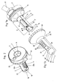
- the holder 7 carries as known per se a handle 8.
- the tube 1 has a respect to the longitudinal axis 6 - apart from the tube sheath opening 9 and the ligature opening 10 - rotationally symmetrical Tubusmantelwand 2 on. This extends from its distal end 3 to its proximal end 4.
- an ultrasonic sensor 12 which is known per se. Its supply lines are hidden in the channel 13.
- the ultrasonic sensor 12 serves to localize an artery. Depending on the orientation of the ultrasonic sensor 12, it can locate these in the region of the ligature opening 10 or the tubular jacket opening 9.
- the ligation opening 10 serves to carry out the HAL operation known per se, while the tuck seam can be attached to the mucosa through the tubular sheath opening 9 which extends longitudinally between its distal end 3 'and its proximal end 4'. But this need not necessarily be so provided. It is entirely conceivable to dispense with the ligature opening 10 and to perform the hall operation in the distal end region of the tubular jacket opening 9.
- the tube sheath opening 9 can be made correspondingly long and the ultrasonic sensor 12 locate the artery in the region of the tube sheath opening 9.
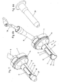
- Fig. 1b shows the closure device 16 of this embodiment in the cavity 17, the tube shell wall 2 can be inserted. It is preferably provided that the shape of the outer surface of the tube shell wall 2 so exactly coincides with the shape of the inner surface of the closure shell wall 21, that upon insertion of the tube shell wall 2 in the cavity 17 of the closure shell wall 21, except for the required for insertion or rotation game, a snug fit is achievable.
- the closure device 16 has a guide portion 20 for exact guidance, which in the assembly position according to the Fig. 2 to 5 in engagement with the guide 14 of the holder 7 of the tube 1 is.
- the closure shell wall 21 accommodating the tube wall 2 is at least in its middle and proximal regions, apart from the closure shell opening 22 -as well as the tube shell wall 2 -rotationally symmetrical and essentially cylindrical with respect to the longitudinal axis 6. Its distal end is designated by 31, its proximal end by 32.
- the distal portion 18 is conically rounded to facilitate insertion into the rectum of the patient.
- Tubus shell wall 2 as well as closure shell wall 21 have in this embodiment, a distal open end.
- the closure shell opening 22 is formed so large that, in a corresponding angular position between the closure device 16 and the tube 1 inserted into the cavity 17 of the closure device 16, it releases both the tube shell opening 9 and the ligature opening 5, ie coincides with them.
- the sheath opening 22 extends longitudinally between the distal end 31 'and the proximal end 32'.
- the webs 23 are provided for supporting the mucosa during the operation. These are integrally formed on the closure shell wall 21 in this embodiment.
- the webs 23 are curved according to the closure shell wall 21 in the circumferential direction 33. The webs 23, spaced apart from one another in this exemplary embodiment and extending parallel, extend only over a first section 22a of the closure shell opening 22.
- a second section 22b of the closure shell opening 22 remains over the entire longitudinal extension of the closure shell opening 22 between the distal end 31 'and the proximal end 32 'completely free of the webs 23. These thus each have a free end and an arranged on the closure shell wall 21 or integrally molded end. As a result, an overall comb or rake-like structure by means of the webs 23 is created.
- the number of ridges 23 may vary depending on the desired spacing and density of the sutures to be applied in the mucosa. Conveniently, between two and six, preferably between three and five webs 23 are provided. In the embodiment shown, the webs 23 are arranged exclusively on the closure shell wall 21. But that does not have to be this way.
- Fig. 2 shows the proximal end of the device.
- the cavity 5 of the tube 1, which is open toward the proximal end 4, can be seen.
- surgical instruments, lighting devices, suction devices and the like can be seen.
- Like. Be introduced into the inner cavity 5 of the tube.
- Fig. 3 shows the closed position of the device in which it is introduced into the rectum of the patient at the beginning of the operation.
- the closure device 16 so twisted against the tube 1 that the closed areas of the closure shell wall 21, the ligature opening 10, as well as the tube shell opening 9 completely cover.
- the closure shell opening 22 is closed by the inner Tubusmantelwand 2.
- the in Fig. 4 shown open position set.
- Fig. 4a schematically shown seams are attached.
- 25 symbolizes the HAL operation known per se in the ligature opening 10.
- the shirring seam illustrated by means of the seams 26a to 26e is placed through the tube sheath opening 9 in the mucosa.
- the distal seam 26a is first of all started.
- the seams 26b, c, d and e are successively attached with the same continuous thread 27.
- the supernatant 28 then remains at the proximal end of the thread 27.
- the webs 23 lying in this position over the tube sheath opening 9 support the mucosa so that they do not pass excessively through the tube sheath opening 9 into the inner cavity 5 of the tube 1 can be pressed.
- the closure device 16 can be further rotated in the circumferential direction 33 until the stop 24 of the closure device 16 abuts the base of the handle 8.
- the webs 23 are no longer arranged in front of the tube shell opening 19.
- the second section 22b of the closure shell opening 22 is brought into coincidence with the tube shell opening 9.
- Fig. 5a shows that too Fig.
- the proximal end 28 of the suture 27 can be knotted with the distal suture 26a, with the proximal suture 26e being guided to the distal suture 26a.
- Other HAL operations may be performed on other arteries after rotating the entire device in the rectum. Often, three or more mucosal events are to be operated on.
- the seams 26a to 26e are not made with a continuous thread 27 but with individual threads, it is also conceivable, as already indicated above, to form the webs 23 so that they traverse the entire closure shell opening 22. It then eliminates the step of twisting from the in Fig. 4 shown position in the in Fig. 5 shown position.
- the tube 1 of the device shown in the embodiment can not only, as based on the Fig. 4a and 5a described, used for a HAL operation or attaching a Raffnaht. It is also possible to treat a hemorrhoid prolapse by rubber band ligation. This type of operation is known per se and in the EP 1 234 539 explained with reference to FIG. 12, so that the surgical technique itself need not be discussed here. However, it should be noted that in this operation, the use of the closure device 16 can be dispensed with. The tube 1 is inserted directly, ie without closure device 16 into the rectum of the patient. The operation can then take place through the distal opening 15 of the tube shell wall 2.
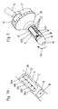
- a drawer body 29 to be inserted into the inner cavity 5 of the tube 1 before insertion of the device into the rectum.
- the distal end of the insertion body 29 is favorably substantially conically shaped and protrudes distally beyond the tube wall 2 in the inserted state.
- the insert body 29 is then removed before the instruments required for the operation are introduced into the cavity 5.
- the 6a to 7 show the tube 1 with drawer body 29. Also shown are the connecting cable 30 for the ultrasonic sensor 12 and optionally provided further surgical aids of the device.
- the dimensioning of the device and the openings in Tubusmantelwand 2 and closure shell wall 21 are conveniently in the range of known in the prior art.
- the protruding over the bracket 7 axial length of the tube 1 is preferably 60 to 100mm.
- the longitudinal extent of the tubular jacket opening 9 is favorably between 40 and 80mm, its width is favorably between 8 and 20mm.
Landscapes
- Health & Medical Sciences (AREA)
- Life Sciences & Earth Sciences (AREA)
- Surgery (AREA)
- Molecular Biology (AREA)
- General Health & Medical Sciences (AREA)
- Veterinary Medicine (AREA)
- Engineering & Computer Science (AREA)
- Biomedical Technology (AREA)
- Heart & Thoracic Surgery (AREA)
- Medical Informatics (AREA)
- Public Health (AREA)
- Animal Behavior & Ethology (AREA)
- Nuclear Medicine, Radiotherapy & Molecular Imaging (AREA)
- Physics & Mathematics (AREA)
- Biophysics (AREA)
- Pathology (AREA)
- Radiology & Medical Imaging (AREA)
- Reproductive Health (AREA)
- Vascular Medicine (AREA)
- Optics & Photonics (AREA)
- Surgical Instruments (AREA)
- Orthopedics, Nursing, And Contraception (AREA)
- Coloring Foods And Improving Nutritive Qualities (AREA)
Abstract
Description
Die vorliegende Erfindung betrifft eine Einrichtung zur Verwendung bei der Behandlung eines Hämorrhoidenprolaps, insbesondere durch HAL-Operation und/oder Anbringen einer Raffungsnaht und/oder einer Gummibandligatur, mit einem Tubus mit einer Tubusmantelwand und einer Verschlusseinrichtung mit einer einen Hohlraum umschließenden Verschlussmantelwand, wobei die Tubusmantelwand im Hohlraum der Verschlussmantelwand verschiebbar und/oder drehbar lagerbar ist und die Tubusmantelwand und die Verschlussmantelwand_ einzeln oder gemeinsam in ein Rektum eines Patienten einführbar sind, wobei die Tubusmaritelwand zumindest eine Tubusmantelöffnung und die Verschlussmantelwand zumindest eine Verschlussmantelöffnung aufweisen und die Tubusmantelöffnung und die Verschlussmantelöffnung in zumindest einer Öffnungsstellung zumindest teilweise miteinander in Deckung bringbar sind.The present invention relates to a device for use in the treatment of a Hämorrhoidenprolaps, in particular by HAL operation and / or attaching a gathering seam and / or a rubber band ligation, with a tube with a Tubusmantelwand and a closure device with a cavity enclosing closure shell wall, the Tubusmantelwand in the cavity of the closure shell wall slidably and / or is rotatably storable and the Tubusmantelwand and the Verschlussmantelwand_ are individually or collectively inserted into a rectum of a patient, wherein the Tubusmaritelwand at least one Tubusmantelöffnung and the closure shell wall at least have a closure shell opening and the Tubusmantelöffnung and the closure shell opening in at least one Opening position are at least partially coincident with each other can be brought.
Bekannt ist bereits die Durchführung einer minimal-invasiven Hämorrhoiden-Arterienligatur mittels einer in das Rektum einzuführenden Ultraschallsonde. Im distalen Bereich eines Tubus ist ein Ultraschallsensor angeordnet, und zwar neben einer Öffnung in der Mantelwand des Tubus. Mittels des Ultraschallsensors wird eine innerhalb der Darmwand verlaufende Hämorrhoiden-Arterie lokalisiert, wobei in der Folge eine Ligatur bzw. eine HAL-Operation der Arterie durch die Öffnung im Tubus erfolgt. Ein Vorteil dieser heute häufig angewendeten Behandlungsmethode ist neben der minimalen Invasivität, dass die Behandlung im Bereich der Darmwand oberhalb der Linea Dentata erfolgt und somit nicht in einem schmerzempfindlichen Bereich. Allerdings kann diese Methode bei einem Hämorrhoidenprolaps des III und IV Grades häufig nicht mehr den gewünschten Behandlungserfolg bringen. Es handelt sich hierbei um ausgeprägte prolabierende Hämorrhoidalpolster (= prolabierende Noduli) bzw. prolabierende Mukosa, die mehr oder weniger ausgeprägt und mehr oder weniger permanent aus dem Anus prolabieren. Derartige Einrichtungen zur Hämorrhoiden-Arterienligatur sind beispielsweise aus der
Es wurden weiters vereinzelt bereits Operationen durchgeführt, bei welchen die prolabierenden Noduli mittels Raffungsnähten gerafft wurden, um den Prolaps wesentlich zu verringern. Diese Operationen haben sich jedoch als technisch schwierig erwiesen, da je nach Befund der Prolaps der Schleimhaut zielgerechte Durchstechungen in diesem Bereich verunmöglicht, die Einhaltung eines ausreichenden Abstands zur Linea Dentata nicht ausreichend kontrollierbar ist (Schmerzen sind die Folge) und der Zeitaufwand für die Einzeldurchstechungen zu groß ist (vier bis fünf Durchstechungen sind meist erforderlich, um zum gewünschten Erfolg zu gelangen).Sporadic operations have been carried out in which the proliferating nodules have been ruffled by means of gathering sutures in order to substantially reduce the prolapse. However, these operations have proved to be technically difficult, as depending on the findings of the prolapse of the mucous membrane targeted Durchstechungen in this area made impossible, compliance with a sufficient distance to the Linea Dentata is not sufficiently controlled (pain is the result) and the time required for the individual Durchstechungen is too large (four to five piercings are usually required to get the desired result).
Eine gattungsgemäße Einrichtung zur Verbesserung dieser Operationsmethode ist bereits aus der
Eine zur
Aufgabe der Erfindung ist es, eine gattungsgemäße Einrichtung dahingehend zu verbessern, dass ein zu weites Eindringen der Mukosa in das Innere des Tubus verhindert ist.The object of the invention is to improve a generic device to the effect that too far penetration of the mucosa is prevented in the interior of the tube.
Dies gelingt durch eine Einrichtung mit den Merkmalen des Patentanspruchs 1.This is achieved by a device having the features of patent claim 1.
Der oder die Stege gewähren einerseits nach wie vor die Möglichkeit, aus dem Inneren des Tubus mit entsprechenden an sich bekannten Operationsinstrumenten durch die Tubusmantelöffnung und die Verschlussmantelöffnung hindurch zur zu operierenden Mukosa zu gelangen. Andererseits stützen der oder die Stege die Mukosa aber in der Form ab, dass ein zu tiefes Eindringen der Mukosa in das Innere des Tubus verhindert ist. Der oder die Stege teilen somit die Operationsöffnung bzw. das Operationsfenster in, vorzugsweise in Längsrichtung des Tubus hintereinander angeordnete, Einzelöffnungen durch die hindurch operiert werden kann.On the one hand, the web or webs still afford the possibility of reaching the mucosa to be operated from the inside of the tube with corresponding operational instruments known per se, through the tube sheath opening and the sheath opening. On the other hand, the web (s) support the mucosa in such a way as to prevent the mucosa from penetrating too deeply into the interior of the tube. The web or webs thus divide the surgical opening or the surgical window in, preferably in the longitudinal direction of the tube successively arranged, individual openings through which can be operated.
Bevorzugt ist dabei vorgesehen, dass die Einrichtung vor der Operation in einer Schließstellung, in der sowohl Verschlussmantelöffnung als auch Tubusmantelöffnung geschlossen sind, in das Rektum des Patienten einführbar ist. Erst kurz vor der Operation wird, vorzugsweise durch Verdrehen der Verschlusseinrichtung gegen den Tubus, ein Operationsfenster durch die in Deckung gebrachte Tubusmantelöffnung und Verschlussmantelöffnung hindurch geöffnet. In dieser sogenannten Öffnungsstellung bleiben die erfindungsgemäßen Stege im Operationsfenster, wodurch die Mukosa während der Operation abgestützt wird. Um das Verdrehen der Verschlusseinrichtung gegen den Tubus zu ermöglichen, ist günstigerweise vorgesehen, dass die Tubusmantelwand und/oder die Verschlussmantelwand abgesehen von darin vorgesehenen Öffnungen zumindest bereichsweise rotationssymmetrisch bezüglich einer Längsachse, vorzugsweise zylinder- oder kegel- oder kegelstumpfförmig, ausgebildet ist (sind).It is preferably provided that the device is inserted into the rectum of the patient before the operation in a closed position in which both the closure shell opening and the tube shell opening are closed. Only shortly before the operation, preferably by turning the closure device against the tube, an operation window is opened through the aligned tube shell opening and closure shell opening. In this so-called open position, the bars according to the invention remain in the operating window, whereby the mucosa is supported during the operation. In order to enable the twisting of the closure device against the tube, it is expediently provided that the tube shell wall and / or the closure shell wall, apart from openings provided therein, at least partially is rotationally symmetrical with respect to a longitudinal axis, preferably cylindrical or conical or frusto-conical, is formed (are).
Durch die Erfindung kann somit eine sehr universell einsetzbare Einrichtung geschaffen werden, mit der eine an sich bekannte sogenannte HAL- bzw. Ligaturoperation wie auch das Anbringen einer Raffungsnaht aber auch eine Gummibandligatur möglich ist. Insbesondere für die Schaffung einer Raffungsnaht ist es günstig, wenn die Tubusmantelöffnung und/oder die Verschlussmantelöffnung zwischen ihrem distalen Ende und ihrem proximalen Ende längserstreckt ist (sind).By the invention thus a very universally applicable device can be created, with a known per se so-called HAL or ligature operation as well as the attachment of a gathering seam but also a rubber band ligation is possible. In particular for the creation of a gather seam, it is favorable if the tube jacket opening and / or the closure jacket opening is (are) extended longitudinally between its distal end and its proximal end.
Im Sinne einer optimalen Abstützung der Mukosa während der Operation ist es günstig, wenn ein jeweiliger Steg beabstandet vom distalen Ende und proximalen Ende der Tubusmantelöffnung und/oder der Verschlussmantelöffnung angeordnet ist.In terms of optimal support of the mucosa during the operation, it is favorable if a respective web is arranged at a distance from the distal end and proximal end of the tube sheath opening and / or the sheath opening.
Im Falle mehrer Stege ist bevorzugt, wenn jeweils zwei benachbarte Stege, vorzugsweise in Längsrichtung der Tubusmantelwand und/oder der Verschlussmantelwand, voneinander beabstandet und/oder parallel zueinander verlaufend angeordnet sind.In the case of multiple webs is preferred if two adjacent webs, preferably in the longitudinal direction of the tube shell wall and / or the closure shell wall, spaced from each other and / or arranged parallel to each other.
Es sind grundsätzlich verschiedene Arten der Ausformung und Anordnung der Stege möglich. Bevorzugt ist aber z. B. wenn ein jeweiliger Steg längserstreckt ist und seine Längserstreckung im Wesentlichen senkrecht zu einer Längsachse der Tubusmantelwand und/oder der Verschlussmantelwand verlaufen. Unter im Wesentlichen senkrecht ist vorzugsweise ein Winkel zwischen 70° und 110°, ganz bevorzugt zwischen 80° und 100°, zu verstehen. Unter einer Längserstreckung wird allgemein verstanden, dass die Ausdehnung eines Gegenstands in Längsrichtung deutlich größer als die Ausdehnung in Querrichtung, also vorzugsweise mindestens das Doppelte der Erstreckung in einer Querrichtung, ist.There are basically different types of formation and arrangement of the webs possible. But is preferably z. B. when a respective web is longitudinally extended and extend its longitudinal extent substantially perpendicular to a longitudinal axis of the tube shell wall and / or the closure shell wall. By substantially perpendicular is preferably an angle between 70 ° and 110 °, most preferably between 80 ° and 100 ° to understand. A longitudinal extent is generally understood to mean that the extent of an object in the longitudinal direction is significantly greater than the extent in the transverse direction, that is to say preferably at least twice the extent in a transverse direction.
Die Begriffe distal und proximal sind in Bezug auf die erfindungsgemäße Einrichtung so zu verstehen, dass sie auf die Seite bezogen sind, die dem Operateur zugewandt ist. Somit ist das distale Ende der Einrichtung das Einführende des Tubus und das proximale Ende das gegenüberliegende Ende der Einrichtung.The terms distal and proximal with respect to the device according to the invention should be understood to refer to the side facing the surgeon. Thus, the distal end of the device is the insertion end of the tube and the proximal end is the opposite end of the device.
Weitere Ausgestaltungsformen und Merkmale der Erfindung werden anhand eines in den Fig. dargestellten bevorzugten Ausführungsbeispiels der Erfindung erläutert.
Dabei zeigen:
- die Fig. 1a und 1b
- den Tubus und die Verschlusseinrichtung des Ausführungsbeispiel in einer Explosionsdarstellung;
- Fig. 2
- eine Ansicht auf das proximale Ende der Einrichtung;
- Fig. 3
- die Schließstellung der Einrichtung, welche beim Einführen in das Rektum des Pa- tienten gewählt wird;
- Fig. 4
- die Öffnungsstellung in der eine Raffungsnaht an der Mukosä angebracht wird;
- Fig. 4a
- eine Ansicht von Innen auf das Operationsfenster;
- Fig. 5
- die Stellung der Verschlusseinrichtung kurz vor Fertigstellung der Raffungsnaht;
- Fig. 5a
- eine entsprechend schematisierte Ansicht auf die Mukosa aus dem Innenhohlraum des Tubus heraus und
- die Fig. 6a bis 7
- eine spezielle Verwendungsform des Tubus der Einrichtung zur Durchfüh- rung einer Gummibandligatur.
Showing:
- Figs. 1a and 1b
- the tube and the closure device of the embodiment in an exploded view;
- Fig. 2
- a view of the proximal end of the device;
- Fig. 3
- the closed position of the device which is chosen when it is inserted into the rectum of the patient;
- Fig. 4
- the opening position in which a gathering seam is attached to the Mukosä;
- Fig. 4a
- a view from inside to the operation window;
- Fig. 5
- the position of the closure device shortly before completion of the gathering seam;
- Fig. 5a
- a corresponding schematized view of the mucosa from the inner cavity of the tube out and
- FIGS. 6a to 7
- a special use of the tube of the device for performing a Gummibandligatur.
Wie weiter unten anhand der
Die Verschlusseinrichtung 16 weist zur exakten Führung einen Führungsabschnitt 20 auf, welcher in der Montagestellung gemäß der
Die Verschlussmantelöffnung 22 ist so groß ausgebildet, dass sie in einer entsprechenden Winkelstellung zwischen der Verschlusseinrichtung 16 und dem in den Hohlraum 17 der Verschlusseinrichtung 16 eingeschobenen Tubus 1 sowohl die Tubusmantelöffnung 9 als auch die Ligaturöffnung 5 frei gibt, also mit diesen in Deckung liegt. Die Verschlussmantelöffnung 22 erstreckt sich in Längsrichtung zwischen dem distalen Ende 31' und dem proximalen Ende 32'. Erfindungsgemäß sind zum Stützen der Mukosa während der Operation die Stege 23 vorgesehen. Diese sind in diesem Ausführungsbeispiel einstückig an der Verschlussmantelwand 21 angeformt. Darüber hinaus sind die Stege 23 entsprechend der Verschlussmantelwand 21 in Umfangsrichtung 33 gekrümmt. Die hier in diesem Ausführungsbeispiel beabstandet voneinander angeordneten und parallel verlaufenden Stege 23 erstrecken sich nur über einen ersten Abschnitt 22a der Verschlussmantelöffnung 22. Es bleibt ein zweiter Abschnitt 22b der Verschlussmantelöffnung 22 über die gesamte Längserstreckung der Verschlussmantelöffnung 22 zwischen distalem Ende-31' und proximalem Ende 32' vollkommen frei von den Stegen 23. Diese weisen somit jeweils ein freies Ende und ein an der Verschlussmantelwand 21 angeordnetes bzw. einstückig angeformtes Ende auf. Hierdurch ist eine insgesamt kamm- bzw. rechenartige Struktur mittels der Stege 23 geschaffen. Die Anzahl der Stege 23 kann je nach gewünschtem Abstand und Dichte der in der Mukosa anzubringenden Nähte variieren. Günstigerweise sind zwischen zwei und sechs, vorzugsweise zwischen drei und fünf Stege 23 vorgesehen. Im gezeigten Ausführungsbeispiel sind die Stege 23 ausschließlich an der Verschlussmantelwand 21 angeordnet. Dies muss aber nicht so sein. Es ist durchaus auch möglich, entsprechende Stege 23 an der Tubusmantelwand 2 bzw. in der Tubusmantelöffnung 9 anzuordnen. Sogar die Anordnung von Stegen 23 an Tubusmantelwand 2 und Verschlussmantelwand 21 ist denkbar, woraus sich eine Struktur mit zwei überlappenden Kämmen ergeben kann. Darüber hinaus kann bei entsprechender Operationstechnik gegebenenfalls auch auf die freien Enden der Stege 23 bzw. den Abschnitt 22b verzichtet werden. In diesem Fall queren die Stege 23 dann die gesamte Verschlussmantelöffnung 22 und/oder Tubusmantelöffnung 9.The
Werden entgegen des gezeigten Beispiels die Nähte 26a bis 26e nicht mit einem durchgehenden Faden 27 sondern mit Einzelfäden angefertigt, so ist es - wie oben bereits angedeutet - auch denkbar, die Stege 23 so lang auszubilden, dass sie die gesamte Verschlussmantelöffnung 22 queren. Es entfällt dann auch der Schritt des Verdrehens aus der in
Der Tubus 1 der im Ausführungsbeispiel gezeigten Einrichtung kann aber nicht nur, wie anhand der
Zur Durchführung der Gummibandligatur wird der Einschubkörper 29 dann entfernt, bevor die zur Operation benötigten Instrumente in den Hohlraum 5 eingeführt werden. Die
Die Dimensionierung der Einrichtung und der Öffnungen in Tubusmantelwand 2 und Verschlussmantelwand 21 liegen günstigerweise im Bereich des beim Stand der Technik bekannten. So beträgt die über die Halterung 7 vorstehende achsiale Länge des Tubus 1 vorzugsweise 60 bis 100mm. Die Längserstreckung der Tubusmantelöffnung 9 liegt günstigerweise zwischen 40 und 80mm, ihre Breite liegt günstigerweise zwischen 8 und 20mm.The dimensioning of the device and the openings in
Unterschiedliche Modifikationen der verschriebenen Ausführungsbeispiele sind denkbar und möglich, ohne den Bereich der Erfindung, wie er in den Ansprüchen definiert ist, zu verlassen.Various modifications of the prescribed embodiments are conceivable and possible without departing from the scope of the invention as defined in the claims.
- 11
- Tubustube
- 22
- Tubusmantelwandtube shell
- 33
- distales Ende der Tubusmantelwanddistal end of the tube wall
- 3'3 '
- distales Ende der Tubusmantelöff- nungdistal end of the tube sheath opening
- 44
- proximales Ende der Tubusmantel- wandproximal end of the tube wall
- 4'4 '
- proximales Ende der Tubus- mantelöffnungproximal end of the tube sheath opening
- 55
- innerer Hohlraum des Tubusinner cavity of the tube
- 66
- Längsachselongitudinal axis
- 77
- Halterungbracket
- 88th
- Handgriffhandle
- 99
- Tubusmantelöffnungtube shell
- 1010
- Ligaturöffnungligature
- 1111
- Zwischensteggutter
- 1212
- Ultraschallsensorultrasonic sensor
- 1313
- Kanalchannel
- 1414
- Führungguide
- 1515
- distale Öffnung der Tubusmantelwanddistal opening of the tube wall
- 1616
- Verschlusseinrichtungclosure device
- 1717
- Hohlraum in VerschlussmantelwandCavity in sealing shell wall
- 1818
- distaler Abschnitt der Verschlusseinrichtungdistal portion of the closure device
- 1919
- distale Öffnung der Verschlussmantelwanddistal opening of the closure shell wall
- 2020
- Führungsabschnitt der VerschlusseinrichtungGuide section of the closure device
- 2121
- VerschlussmantelwandClosure shell wall
- 2222
- VerschlussmantelöffnungClosure shell opening
- 22a22a
- erster Abschnittfirst section
- 22b22b
- zweiter Abschnittsecond part
- 2323
- Stegweb
- 2424
- Anschlagattack
- 2525
- HAL-OperationHAL operation
- 26a26a
- Naht der RaffnahtSeam of the gather seam
- 26b26b
- Naht der RaffnahtSeam of the gather seam
- 26c26c
- Naht der RaffnahtSeam of the gather seam
- 26d26d
- Naht der RaffnahtSeam of the gather seam
- 26e26e
- Naht der RaffnahtSeam of the gather seam
- 2727
- Fadenthread
- 2828
- proximales Ende des Fadensproximal end of the thread
- 2929
- Einschubkörperplug-in unit
- 3030
- Anschlusskabelconnection cable
- 3131
- distales Ende der Verschlussmantelwanddistal end of the closure shell wall
- 31'31 '
- distales Ende der Verschlussmantelöffnungdistal end of the closure shell opening
- 3232
- proximales Ende der Verschlussmantelwandproximal end of the closure shell wall
- 32'32 '
- proximales Ende der Verschlussmantelöffnungproximal end of the closure shell opening
- 3333
- Umfangsrichtungcircumferentially
Claims (15)
- A device for use in the treatment of a haemorrhoid prolapse, in particular by HAL surgery and/or the attachment of a gathering suture and/or an elastic-band ligature, having a tube with a tube casing wall and a closure device with a closure casing wall which encloses a cavity, wherein the tube casing wall can be displaecably and/or rotatably mounted in the cavity of the closure casing wall and the tube casing wall and the closure casing wall are insertable, individually or together, into a rectum of a patient, wherein the tube casing wall has at least one tube casing opening and the closure casing wall has at least one closure casing opening and the tube casing opening and the closure casing opening can, in at least one open position, be brought into at least partial congruence with one another, characterised in that at least one arm (23), arranged on the tube casing wall (2) and/or on the closure casing wall (21) is provided, which arm (23) at least partially projects into the tube casing opening (9) and/or into the closure casing opening (22).
- A device according to claim 1, characterised in that a plurality of arms (23) arranged on the tube casing wall (2) and/or on the closure casing wall (21) are provided, which at least partially project into the tube casing opening (9) and/or into the closure casing opening (22).
- A device according to claim 1 or 2, characterised in that the tube casing wall (2) and/or the closure casing wall (21) is (are) elongate between a distal end (3, 31) and a proximal end (4, 32).
- A device according to any one of claims 1 to 3, characterised in that at least regions of the tube casing wall (2) and/or the closure casing wall (21) are, with the exception of openings provided therein, rotationally symmetrical with respect to a longitudinal axis (6), are preferably in the form of a cylinder or a cone or a truncated cone.
- A device according to any one of claims 1 to 4, characterised in that the tube casing opening (9) and/or the closure casing opening (22) is (are) elongate between their distal end (3', 31') and their proximal end (4', 32'), and/or in that the tube casing wall (2) encloses a cavity (5), open towards the proximal end (4), for the insertion of surgical instruments.
- A device according to any one of claims 1 to 5, characterised in that a respective arm (23) is arranged at a distance from the distal end (3', 31') and from the proximal end (4', 32') of the tube casing opening (9) and/or the cloture casing opening (22).
- A device according to any one of claims 1 to 6, characterised in that in the event of a plurality of arms (23), in each case two adjacent arms (23) are arranged at a distance from one another, preferably running parallel to one another.
- A device according to any one of claims 1 to 7, characterised in that a respective arm (23) is elongate and its longitudinal extension runs substantially perpendicular to a longitudinal axis (6) of the tube casing wall (2) and/or the closure casing wall (21).
- A device according to any one of claims 1 to 8, characterised in that a respective arm (23) is, in a circumferential direction (33) of the tube casing wall (2) or the closure casing wall (21), curved in the manner thereof, and/or in that a respective arm (23) is integrally formed on the tube casing wall (2) and/or the closure casing wall (21).
- A device according to any one of claims 1 to 9, characterised in that the arm (23) or the arms (23) extend only over a first portion (22a) of the tube casing opening (9) and/or the closure casing opening (22), and a second portion (22b), preferably extending from the distal end (3', 31') to the proximal end (4', 32') of the tube casing opening (9) and/or the closure casing opening (22), of the tube casing opening (9) and/or the closure casing opening (22) is devoid of arms (23).
- A device according to any one of claims 1 to 10, characterised in that a respective arm (23) has in each case a free end and an end arranged on the tube casing wall (2) and/or the closure casing wall (21), and/or in that the tube casing wall (2) and/or the closure casing wall (21) has (have) a distally open end (15, 19).
- A device according to any one of claims 1 to 11, characterised in that the form of the outer surface of the tube casing wall (2) corresponds to the form of the inner surface of the closure casing wall (21) so exactly that a snug fit can be achieved upon insertion of the tube casing wall (2) into the cavity (17) of the closure casing wall (21) except for the play required for insertion or rotation as the case may be
- A device according to any one of claims 1 to 12, characterised in that an ultrasonic sensor (12) for localization of an artery is provided, preferably on or in the tube casing wall (2), and/or in that in addition to the tube casing opening (9), the tube casing wall (2) has a ligature opening (10) separated from the tube casing opening (9) by an intermediate arm (11).
- A device according to claim 13, characterised in that the ultrasonic sensor (12) is arranged on the intermediate arm (11).
- A device according to one of claims 13 and 14, characterised in that the ultrasonic sensor (12) is provided for artery localisation in the region of the ligature opening (10) or the tube casing opening (9).
Applications Claiming Priority (2)
| Application Number | Priority Date | Filing Date | Title |
|---|---|---|---|
| AT0063207A AT505002B1 (en) | 2007-04-23 | 2007-04-23 | DEVICE FOR USE IN THE TREATMENT OF A HEMORRHOIDENEPROLAP |
| PCT/AT2008/000123 WO2008128261A1 (en) | 2007-04-23 | 2008-04-04 | Device for use for the treatment of hemorrhoid prolapse |
Publications (2)
| Publication Number | Publication Date |
|---|---|
| EP2139403A1 EP2139403A1 (en) | 2010-01-06 |
| EP2139403B1 true EP2139403B1 (en) | 2010-07-14 |
Family
ID=39638080
Family Applications (1)
| Application Number | Title | Priority Date | Filing Date |
|---|---|---|---|
| EP08714316A Not-in-force EP2139403B1 (en) | 2007-04-23 | 2008-04-04 | Device for use for the treatment of hemorrhoid prolapse |
Country Status (10)
| Country | Link |
|---|---|
| US (1) | US8394012B2 (en) |
| EP (1) | EP2139403B1 (en) |
| JP (1) | JP5329528B2 (en) |
| KR (1) | KR101475542B1 (en) |
| CN (1) | CN101668487B (en) |
| AT (2) | AT505002B1 (en) |
| AU (1) | AU2008241339B2 (en) |
| DE (1) | DE502008000957D1 (en) |
| ES (1) | ES2348833T3 (en) |
| WO (1) | WO2008128261A1 (en) |
Cited By (1)
| Publication number | Priority date | Publication date | Assignee | Title |
|---|---|---|---|---|
| DE102013009615A1 (en) * | 2013-04-09 | 2014-10-09 | Gerhard Schmitt | Device for the treatment of hemorrhoids |
Families Citing this family (21)
| Publication number | Priority date | Publication date | Assignee | Title |
|---|---|---|---|---|
| US9204789B2 (en) * | 2009-10-08 | 2015-12-08 | Covidien Lp | Asymmetrical anoscope |
| CN102217964B (en) * | 2010-04-15 | 2016-04-27 | 韩美药品株式会社 | For the hemorrhoid artery ligation device of hemorrhoid treating |
| CN101828932A (en) * | 2010-04-23 | 2010-09-15 | 南京奥珂森电子有限公司 | Proctoscopic ultrasonic Doppler probe |
| CN101991904B (en) * | 2010-12-10 | 2013-06-05 | 苏州天臣国际医疗科技有限公司 | Anal dilator |
| CN103815941B (en) * | 2014-02-28 | 2016-06-22 | 南京奥珂森电子有限公司 | Split type Proctoscopic ultrasonic Doppler probe |
| CN105311732B (en) * | 2014-07-25 | 2018-09-25 | 北京派尔特医疗科技股份有限公司 | A kind of auxiliary dress of anal-surgery is set |
| CN106236177B (en) * | 2016-08-24 | 2018-12-04 | 江苏特普优微创医疗科技有限公司 | Set rolling circle and hemorrhoid cover bundle method |
| US11497507B2 (en) | 2017-02-19 | 2022-11-15 | Orpheus Ventures, Llc | Systems and methods for closing portions of body tissue |
| SE541467C2 (en) * | 2017-10-13 | 2019-10-08 | Dev Ab | Device for use in the treatment of hemorrhoids |
| CN108175372B (en) * | 2018-01-10 | 2023-05-30 | 苏州贝诺医疗器械有限公司 | Rectal prolapse measuring instrument |
| CN109350144B (en) * | 2018-12-05 | 2023-12-08 | 江西安联医疗器械有限公司 | Multifunctional surgical incision retraction protection device |
| US11678786B2 (en) * | 2019-07-16 | 2023-06-20 | Boston Scientific Scimed, Inc. | Device and methods for inspection and treatment of hemorrhoids |
| CN110743093A (en) * | 2019-11-27 | 2020-02-04 | 山东大乐医疗器械有限公司 | Anus compression hemostasis drug delivery device |
| AU2021234312B9 (en) * | 2020-03-12 | 2024-12-05 | Boston Scientific Scimed, Inc. | Devices and methods for tissue ligation |
| CN116963659A (en) * | 2021-01-06 | 2023-10-27 | 杰·伊姆 | Methods and systems for treating hemorrhoids |
| ES2997185T3 (en) * | 2021-02-04 | 2025-02-14 | Dev Ab | Proctoscope |
| CN114711853B (en) * | 2022-04-13 | 2024-09-27 | 张勇 | Auxiliary cleaning equipment for hemorrhoid operation for general surgery diseases |
| CN117442236B (en) * | 2023-12-22 | 2024-03-08 | 吉林大学 | B ultrasonic probe for expanding anus based on rotation |
| AT528075B1 (en) * | 2024-03-13 | 2025-11-15 | Ami Agency Medical Innovations Gmbh | Device for use during surgical procedures in the rectal area |
| US12419642B1 (en) | 2024-08-19 | 2025-09-23 | Labella Health Care Llc | Hemorrhoid bander and method of use thereof |
| CN119367667B (en) * | 2024-12-31 | 2025-05-06 | 温州医科大学附属第一医院 | Mechanical decompression type drug delivery and minimally invasive surgical operation device for colorectal anus |
Family Cites Families (28)
| Publication number | Priority date | Publication date | Assignee | Title |
|---|---|---|---|---|
| DE8316987U1 (en) | 1983-11-10 | Berger, Zoltan, 7770 Überlingen | Proctoscope | |
| US295798A (en) * | 1884-03-25 | Speculum | ||
| US3774596A (en) * | 1971-06-29 | 1973-11-27 | G Cook | Compliable cavity speculum |
| US5025778A (en) | 1990-03-26 | 1991-06-25 | Opielab, Inc. | Endoscope with potential channels and method of using the same |
| WO1992021279A1 (en) * | 1991-06-06 | 1992-12-10 | Meditech International Pty Ltd | Speculum |
| JP2510074B2 (en) * | 1993-12-27 | 1996-06-26 | 林電気株式会社 | Internal hemorrhoid treatment jig |
| JP4262474B2 (en) * | 1995-01-20 | 2009-05-13 | オリンパス株式会社 | Ligation device |
| US5570692A (en) * | 1995-05-19 | 1996-11-05 | Hayashi Denki Co. Ltd. | Ultrasonic doppler blood flow detector for hemorrhoid artery ligation |
| AU8507398A (en) * | 1997-07-24 | 1999-02-16 | James F. Mcguckin Jr. | Breast surgery method and apparatus |
| JP3429685B2 (en) | 1997-10-06 | 2003-07-22 | オリンパス光学工業株式会社 | Endoscope guide tube |
| CN1235851A (en) * | 1998-05-20 | 1999-11-24 | 范良藻 | Electric pulse recovery device |
| US6126594A (en) * | 1998-07-21 | 2000-10-03 | Bayer; Izhack | Anoscope for internal hemorrhoidectomy |
| US6142933A (en) | 1998-11-23 | 2000-11-07 | Ethicon Endo-Surgery, Inc. | Anoscope for hemorrhoidal surgery |
| US7131943B2 (en) * | 2000-03-09 | 2006-11-07 | Ethicon, Inc. | Surgical instrument and method for treating organ prolapse conditions |
| US20060009797A1 (en) * | 2001-01-09 | 2006-01-12 | Armstrong David N | Anoscope |
| EP1234539A3 (en) | 2001-02-15 | 2002-09-11 | AMI (Agency for medical innovations GmbH) | Device for use during the ligature of an intramural artery in a body cavity |
| EP2292182A1 (en) * | 2001-03-09 | 2011-03-09 | Boston Scientific Limited | System for implanting an implant |
| US6632227B2 (en) | 2001-08-24 | 2003-10-14 | Scimed Life Systems, Inc. | Endoscopic resection devices |
| JP4059659B2 (en) * | 2001-11-19 | 2008-03-12 | オリンパス株式会社 | Treatment sheath |
| CA2363473C (en) | 2001-11-20 | 2010-10-19 | Marc G. Morin | Anoscope |
| JP4025905B2 (en) * | 2002-02-14 | 2007-12-26 | 幸康 奥村 | Anoscope |
| DE10231004A1 (en) | 2002-07-09 | 2004-01-22 | Dwl Elektronische Systeme Gmbh | proctoscope |
| ITMO20020246A1 (en) | 2002-09-09 | 2004-03-10 | Francesco Sias | ROTATING OPERATING ANOSCOPE. |
| WO2004064624A1 (en) | 2003-01-21 | 2004-08-05 | Metech S.R.L. | A retractor for operations on the arteria haemorroidalis |
| US20050234305A1 (en) * | 2004-04-15 | 2005-10-20 | Frederick Licciardi | Medical device and system for providing an image |
| AT501766A1 (en) * | 2005-01-25 | 2006-11-15 | Ami Gmbh | DEVICE FOR USE IN THE TREATMENT OF A HEMORRHOIDENEPROLAP |
| WO2007016946A1 (en) * | 2005-08-09 | 2007-02-15 | Ethicon Endo-Surgery, Inc. | Rectally insertable surgical system |
| ITTO20080032U1 (en) * | 2007-05-11 | 2008-09-12 | Ceramoptec Gmbh | SYSTEM AND METHOD FOR HEMORROID TREATMENT |
-
2007
- 2007-04-23 AT AT0063207A patent/AT505002B1/en not_active IP Right Cessation
-
2008
- 2008-04-04 ES ES08714316T patent/ES2348833T3/en active Active
- 2008-04-04 WO PCT/AT2008/000123 patent/WO2008128261A1/en not_active Ceased
- 2008-04-04 DE DE502008000957T patent/DE502008000957D1/en active Active
- 2008-04-04 AU AU2008241339A patent/AU2008241339B2/en not_active Ceased
- 2008-04-04 CN CN200880013247XA patent/CN101668487B/en not_active Expired - Fee Related
- 2008-04-04 KR KR1020097024065A patent/KR101475542B1/en not_active Expired - Fee Related
- 2008-04-04 JP JP2010504373A patent/JP5329528B2/en not_active Expired - Fee Related
- 2008-04-04 US US12/597,400 patent/US8394012B2/en active Active
- 2008-04-04 AT AT08714316T patent/ATE473694T1/en active
- 2008-04-04 EP EP08714316A patent/EP2139403B1/en not_active Not-in-force
Cited By (1)
| Publication number | Priority date | Publication date | Assignee | Title |
|---|---|---|---|---|
| DE102013009615A1 (en) * | 2013-04-09 | 2014-10-09 | Gerhard Schmitt | Device for the treatment of hemorrhoids |
Also Published As
| Publication number | Publication date |
|---|---|
| ES2348833T3 (en) | 2010-12-15 |
| WO2008128261A1 (en) | 2008-10-30 |
| AU2008241339A1 (en) | 2008-10-30 |
| AU2008241339B2 (en) | 2013-08-15 |
| AT505002B1 (en) | 2008-10-15 |
| CN101668487A (en) | 2010-03-10 |
| US20100130857A1 (en) | 2010-05-27 |
| CN101668487B (en) | 2011-07-20 |
| ATE473694T1 (en) | 2010-07-15 |
| US8394012B2 (en) | 2013-03-12 |
| DE502008000957D1 (en) | 2010-08-26 |
| JP2010524596A (en) | 2010-07-22 |
| JP5329528B2 (en) | 2013-10-30 |
| KR101475542B1 (en) | 2014-12-30 |
| EP2139403A1 (en) | 2010-01-06 |
| AT505002A4 (en) | 2008-10-15 |
| KR20100017124A (en) | 2010-02-16 |
Similar Documents
| Publication | Publication Date | Title |
|---|---|---|
| EP2139403B1 (en) | Device for use for the treatment of hemorrhoid prolapse | |
| EP1683473B1 (en) | Device for use in treatment of hemorrhoidal prolapse | |
| EP0815796B1 (en) | Trocar for laparoscopic operations | |
| EP1281360B1 (en) | Surgical instrument for endoscopic use | |
| EP2049037B1 (en) | Device for introducing and positioning surgical instruments | |
| EP3897343B1 (en) | Endoscope comprising quick-change tubes | |
| DE3504292C1 (en) | Instrument for endoscopic interventions, especially for percutaneous gallstone removal or gallbladder surgery | |
| EP2185061B1 (en) | Trocar tube, trocar, obturator, or rectoscope for transluminal endoscopic surgery via natural body cavities | |
| EP2725962B1 (en) | Trocar system | |
| DE60028863T2 (en) | Electrosurgical handpiece for the treatment of tissue | |
| DE19855968C1 (en) | Medical reed shaft instrument | |
| EP1610695B1 (en) | Surgical instrument system | |
| DE102005004318A1 (en) | Surgical seam system | |
| EP0432560A2 (en) | Set of instruments to close hollow organs and wounds | |
| WO1996008204A1 (en) | Surgical instrument | |
| DE102019101987A1 (en) | Device for the transurethral treatment of benign prostatic hyperplasia | |
| EP1601293B1 (en) | Medical equipment for creating a surgical space for oral surgery | |
| DE4115548C2 (en) | Surgical forceps for use in laparoscopy | |
| EP2725988B1 (en) | Trocar system | |
| DE19629537A1 (en) | Trocar sleeve | |
| WO2009000854A1 (en) | Surgical instrument | |
| DE102016122543A1 (en) | Surgical rod element and instrument set for the minimally invasive execution of a single suture | |
| DE102012203908B3 (en) | Instrument system for minimally invasive surgery in the single-port technique | |
| DE19937043C2 (en) | Medical instrument for creating a cavity for an endoscopic procedure | |
| DE19813914A1 (en) | Specifically shaped surgical nail for treatment of pet with fractured bone |
Legal Events
| Date | Code | Title | Description |
|---|---|---|---|
| PUAI | Public reference made under article 153(3) epc to a published international application that has entered the european phase |
Free format text: ORIGINAL CODE: 0009012 |
|
| 17P | Request for examination filed |
Effective date: 20091013 |
|
| AK | Designated contracting states |
Kind code of ref document: A1 Designated state(s): AT BE BG CH CY CZ DE DK EE ES FI FR GB GR HR HU IE IS IT LI LT LU LV MC MT NL NO PL PT RO SE SI SK TR |
|
| GRAP | Despatch of communication of intention to grant a patent |
Free format text: ORIGINAL CODE: EPIDOSNIGR1 |
|
| GRAS | Grant fee paid |
Free format text: ORIGINAL CODE: EPIDOSNIGR3 |
|
| GRAA | (expected) grant |
Free format text: ORIGINAL CODE: 0009210 |
|
| AK | Designated contracting states |
Kind code of ref document: B1 Designated state(s): AT BE BG CH CY CZ DE DK EE ES FI FR GB GR HR HU IE IS IT LI LT LU LV MC MT NL NO PL PT RO SE SI SK TR |
|
| REG | Reference to a national code |
Ref country code: GB Ref legal event code: FG4D Free format text: NOT ENGLISH |
|
| REG | Reference to a national code |
Ref country code: CH Ref legal event code: EP |
|
| REG | Reference to a national code |
Ref country code: IE Ref legal event code: FG4D |
|
| REF | Corresponds to: |
Ref document number: 502008000957 Country of ref document: DE Date of ref document: 20100826 Kind code of ref document: P |
|
| REG | Reference to a national code |
Ref country code: SE Ref legal event code: TRGR |
|
| REG | Reference to a national code |
Ref country code: NL Ref legal event code: VDEP Effective date: 20100714 |
|
| REG | Reference to a national code |
Ref country code: ES Ref legal event code: FG2A Effective date: 20101201 |
|
| LTIE | Lt: invalidation of european patent or patent extension |
Effective date: 20100714 |
|
| PG25 | Lapsed in a contracting state [announced via postgrant information from national office to epo] |
Ref country code: FI Free format text: LAPSE BECAUSE OF FAILURE TO SUBMIT A TRANSLATION OF THE DESCRIPTION OR TO PAY THE FEE WITHIN THE PRESCRIBED TIME-LIMIT Effective date: 20100714 Ref country code: NO Free format text: LAPSE BECAUSE OF FAILURE TO SUBMIT A TRANSLATION OF THE DESCRIPTION OR TO PAY THE FEE WITHIN THE PRESCRIBED TIME-LIMIT Effective date: 20101014 Ref country code: LT Free format text: LAPSE BECAUSE OF FAILURE TO SUBMIT A TRANSLATION OF THE DESCRIPTION OR TO PAY THE FEE WITHIN THE PRESCRIBED TIME-LIMIT Effective date: 20100714 Ref country code: NL Free format text: LAPSE BECAUSE OF FAILURE TO SUBMIT A TRANSLATION OF THE DESCRIPTION OR TO PAY THE FEE WITHIN THE PRESCRIBED TIME-LIMIT Effective date: 20100714 |
|
| REG | Reference to a national code |
Ref country code: IE Ref legal event code: FD4D |
|
| PG25 | Lapsed in a contracting state [announced via postgrant information from national office to epo] |
Ref country code: BG Free format text: LAPSE BECAUSE OF FAILURE TO SUBMIT A TRANSLATION OF THE DESCRIPTION OR TO PAY THE FEE WITHIN THE PRESCRIBED TIME-LIMIT Effective date: 20101014 Ref country code: PL Free format text: LAPSE BECAUSE OF FAILURE TO SUBMIT A TRANSLATION OF THE DESCRIPTION OR TO PAY THE FEE WITHIN THE PRESCRIBED TIME-LIMIT Effective date: 20100714 Ref country code: SI Free format text: LAPSE BECAUSE OF FAILURE TO SUBMIT A TRANSLATION OF THE DESCRIPTION OR TO PAY THE FEE WITHIN THE PRESCRIBED TIME-LIMIT Effective date: 20100714 Ref country code: CY Free format text: LAPSE BECAUSE OF FAILURE TO SUBMIT A TRANSLATION OF THE DESCRIPTION OR TO PAY THE FEE WITHIN THE PRESCRIBED TIME-LIMIT Effective date: 20100714 Ref country code: IS Free format text: LAPSE BECAUSE OF FAILURE TO SUBMIT A TRANSLATION OF THE DESCRIPTION OR TO PAY THE FEE WITHIN THE PRESCRIBED TIME-LIMIT Effective date: 20101114 Ref country code: HR Free format text: LAPSE BECAUSE OF FAILURE TO SUBMIT A TRANSLATION OF THE DESCRIPTION OR TO PAY THE FEE WITHIN THE PRESCRIBED TIME-LIMIT Effective date: 20100714 |
|
| PG25 | Lapsed in a contracting state [announced via postgrant information from national office to epo] |
Ref country code: GR Free format text: LAPSE BECAUSE OF FAILURE TO SUBMIT A TRANSLATION OF THE DESCRIPTION OR TO PAY THE FEE WITHIN THE PRESCRIBED TIME-LIMIT Effective date: 20101015 Ref country code: LV Free format text: LAPSE BECAUSE OF FAILURE TO SUBMIT A TRANSLATION OF THE DESCRIPTION OR TO PAY THE FEE WITHIN THE PRESCRIBED TIME-LIMIT Effective date: 20100714 |
|
| PG25 | Lapsed in a contracting state [announced via postgrant information from national office to epo] |
Ref country code: IE Free format text: LAPSE BECAUSE OF FAILURE TO SUBMIT A TRANSLATION OF THE DESCRIPTION OR TO PAY THE FEE WITHIN THE PRESCRIBED TIME-LIMIT Effective date: 20100714 Ref country code: DK Free format text: LAPSE BECAUSE OF FAILURE TO SUBMIT A TRANSLATION OF THE DESCRIPTION OR TO PAY THE FEE WITHIN THE PRESCRIBED TIME-LIMIT Effective date: 20100714 |
|
| PLBE | No opposition filed within time limit |
Free format text: ORIGINAL CODE: 0009261 |
|
| STAA | Information on the status of an ep patent application or granted ep patent |
Free format text: STATUS: NO OPPOSITION FILED WITHIN TIME LIMIT |
|
| PG25 | Lapsed in a contracting state [announced via postgrant information from national office to epo] |
Ref country code: EE Free format text: LAPSE BECAUSE OF FAILURE TO SUBMIT A TRANSLATION OF THE DESCRIPTION OR TO PAY THE FEE WITHIN THE PRESCRIBED TIME-LIMIT Effective date: 20100714 Ref country code: RO Free format text: LAPSE BECAUSE OF FAILURE TO SUBMIT A TRANSLATION OF THE DESCRIPTION OR TO PAY THE FEE WITHIN THE PRESCRIBED TIME-LIMIT Effective date: 20100714 Ref country code: IT Free format text: LAPSE BECAUSE OF FAILURE TO SUBMIT A TRANSLATION OF THE DESCRIPTION OR TO PAY THE FEE WITHIN THE PRESCRIBED TIME-LIMIT Effective date: 20100714 Ref country code: CZ Free format text: LAPSE BECAUSE OF FAILURE TO SUBMIT A TRANSLATION OF THE DESCRIPTION OR TO PAY THE FEE WITHIN THE PRESCRIBED TIME-LIMIT Effective date: 20100714 Ref country code: SK Free format text: LAPSE BECAUSE OF FAILURE TO SUBMIT A TRANSLATION OF THE DESCRIPTION OR TO PAY THE FEE WITHIN THE PRESCRIBED TIME-LIMIT Effective date: 20100714 |
|
| 26N | No opposition filed |
Effective date: 20110415 |
|
| REG | Reference to a national code |
Ref country code: DE Ref legal event code: R097 Ref document number: 502008000957 Country of ref document: DE Effective date: 20110415 |
|
| PG25 | Lapsed in a contracting state [announced via postgrant information from national office to epo] |
Ref country code: MC Free format text: LAPSE BECAUSE OF NON-PAYMENT OF DUE FEES Effective date: 20110430 |
|
| PG25 | Lapsed in a contracting state [announced via postgrant information from national office to epo] |
Ref country code: MT Free format text: LAPSE BECAUSE OF FAILURE TO SUBMIT A TRANSLATION OF THE DESCRIPTION OR TO PAY THE FEE WITHIN THE PRESCRIBED TIME-LIMIT Effective date: 20100714 |
|
| REG | Reference to a national code |
Ref country code: CH Ref legal event code: PL |
|
| PG25 | Lapsed in a contracting state [announced via postgrant information from national office to epo] |
Ref country code: LI Free format text: LAPSE BECAUSE OF NON-PAYMENT OF DUE FEES Effective date: 20120430 Ref country code: CH Free format text: LAPSE BECAUSE OF NON-PAYMENT OF DUE FEES Effective date: 20120430 |
|
| PG25 | Lapsed in a contracting state [announced via postgrant information from national office to epo] |
Ref country code: LU Free format text: LAPSE BECAUSE OF NON-PAYMENT OF DUE FEES Effective date: 20110404 |
|
| PG25 | Lapsed in a contracting state [announced via postgrant information from national office to epo] |
Ref country code: PT Free format text: LAPSE BECAUSE OF NON-PAYMENT OF DUE FEES Effective date: 20100714 |
|
| PG25 | Lapsed in a contracting state [announced via postgrant information from national office to epo] |
Ref country code: TR Free format text: LAPSE BECAUSE OF FAILURE TO SUBMIT A TRANSLATION OF THE DESCRIPTION OR TO PAY THE FEE WITHIN THE PRESCRIBED TIME-LIMIT Effective date: 20100714 |
|
| PG25 | Lapsed in a contracting state [announced via postgrant information from national office to epo] |
Ref country code: HU Free format text: LAPSE BECAUSE OF FAILURE TO SUBMIT A TRANSLATION OF THE DESCRIPTION OR TO PAY THE FEE WITHIN THE PRESCRIBED TIME-LIMIT Effective date: 20100714 |
|
| REG | Reference to a national code |
Ref country code: DE Ref legal event code: R082 Ref document number: 502008000957 Country of ref document: DE Representative=s name: TARVENKORN & WICKORD PATENTANWAELTE PARTG MBB, DE |
|
| REG | Reference to a national code |
Ref country code: FR Ref legal event code: PLFP Year of fee payment: 9 |
|
| REG | Reference to a national code |
Ref country code: FR Ref legal event code: PLFP Year of fee payment: 10 |
|
| REG | Reference to a national code |
Ref country code: FR Ref legal event code: PLFP Year of fee payment: 11 |
|
| PGFP | Annual fee paid to national office [announced via postgrant information from national office to epo] |
Ref country code: AT Payment date: 20180418 Year of fee payment: 11 |
|
| PGFP | Annual fee paid to national office [announced via postgrant information from national office to epo] |
Ref country code: SE Payment date: 20180427 Year of fee payment: 11 |
|
| REG | Reference to a national code |
Ref country code: SE Ref legal event code: EUG |
|
| REG | Reference to a national code |
Ref country code: AT Ref legal event code: MM01 Ref document number: 473694 Country of ref document: AT Kind code of ref document: T Effective date: 20190404 |
|
| PG25 | Lapsed in a contracting state [announced via postgrant information from national office to epo] |
Ref country code: AT Free format text: LAPSE BECAUSE OF NON-PAYMENT OF DUE FEES Effective date: 20190404 Ref country code: SE Free format text: LAPSE BECAUSE OF NON-PAYMENT OF DUE FEES Effective date: 20190405 |
|
| PGFP | Annual fee paid to national office [announced via postgrant information from national office to epo] |
Ref country code: GB Payment date: 20220419 Year of fee payment: 15 Ref country code: FR Payment date: 20220427 Year of fee payment: 15 Ref country code: ES Payment date: 20220513 Year of fee payment: 15 Ref country code: DE Payment date: 20220428 Year of fee payment: 15 |
|
| PGFP | Annual fee paid to national office [announced via postgrant information from national office to epo] |
Ref country code: BE Payment date: 20220427 Year of fee payment: 15 |
|
| REG | Reference to a national code |
Ref country code: DE Ref legal event code: R119 Ref document number: 502008000957 Country of ref document: DE |
|
| GBPC | Gb: european patent ceased through non-payment of renewal fee |
Effective date: 20230404 |
|
| REG | Reference to a national code |
Ref country code: BE Ref legal event code: MM Effective date: 20230430 |
|
| PG25 | Lapsed in a contracting state [announced via postgrant information from national office to epo] |
Ref country code: GB Free format text: LAPSE BECAUSE OF NON-PAYMENT OF DUE FEES Effective date: 20230404 |
|
| PG25 | Lapsed in a contracting state [announced via postgrant information from national office to epo] |
Ref country code: GB Free format text: LAPSE BECAUSE OF NON-PAYMENT OF DUE FEES Effective date: 20230404 Ref country code: FR Free format text: LAPSE BECAUSE OF NON-PAYMENT OF DUE FEES Effective date: 20230430 Ref country code: DE Free format text: LAPSE BECAUSE OF NON-PAYMENT OF DUE FEES Effective date: 20231103 |
|
| PG25 | Lapsed in a contracting state [announced via postgrant information from national office to epo] |
Ref country code: BE Free format text: LAPSE BECAUSE OF NON-PAYMENT OF DUE FEES Effective date: 20230430 |
|
| REG | Reference to a national code |
Ref country code: ES Ref legal event code: FD2A Effective date: 20240527 |
|
| PG25 | Lapsed in a contracting state [announced via postgrant information from national office to epo] |
Ref country code: ES Free format text: LAPSE BECAUSE OF NON-PAYMENT OF DUE FEES Effective date: 20230405 |
|
| PG25 | Lapsed in a contracting state [announced via postgrant information from national office to epo] |
Ref country code: ES Free format text: LAPSE BECAUSE OF NON-PAYMENT OF DUE FEES Effective date: 20230405 |