EP2139296B1 - LED illuminating device - Google Patents
LED illuminating device Download PDFInfo
- Publication number
- EP2139296B1 EP2139296B1 EP09163665.4A EP09163665A EP2139296B1 EP 2139296 B1 EP2139296 B1 EP 2139296B1 EP 09163665 A EP09163665 A EP 09163665A EP 2139296 B1 EP2139296 B1 EP 2139296B1
- Authority
- EP
- European Patent Office
- Prior art keywords
- light
- leds
- led
- color
- illuminating device
- Prior art date
- Legal status (The legal status is an assumption and is not a legal conclusion. Google has not performed a legal analysis and makes no representation as to the accuracy of the status listed.)
- Not-in-force
Links
- 239000003086 colorant Substances 0.000 claims description 28
- 239000000758 substrate Substances 0.000 claims description 12
- 230000014509 gene expression Effects 0.000 claims description 9
- 238000005192 partition Methods 0.000 claims description 3
- 238000010586 diagram Methods 0.000 claims description 2
- 239000000203 mixture Substances 0.000 claims 2
- 230000004907 flux Effects 0.000 description 21
- 238000005562 fading Methods 0.000 description 6
- 230000000694 effects Effects 0.000 description 4
- 238000002834 transmittance Methods 0.000 description 4
- 238000005286 illumination Methods 0.000 description 3
- 238000005452 bending Methods 0.000 description 2
- 238000000034 method Methods 0.000 description 2
- 238000001514 detection method Methods 0.000 description 1
Images


Classifications
-
- H—ELECTRICITY
- H05—ELECTRIC TECHNIQUES NOT OTHERWISE PROVIDED FOR
- H05B—ELECTRIC HEATING; ELECTRIC LIGHT SOURCES NOT OTHERWISE PROVIDED FOR; CIRCUIT ARRANGEMENTS FOR ELECTRIC LIGHT SOURCES, IN GENERAL
- H05B45/00—Circuit arrangements for operating light-emitting diodes [LED]
- H05B45/20—Controlling the colour of the light
Definitions
- the present invention relates to a LED illuminating device that employs a plurality of LEDs emitting different light colors as a light source and that has a function for changing a light color by dimming each of the LEDs.
- Japanese Unexamined Patent Publication No. 2001-93305 discloses a conventional LED illuminating device.
- This device includes: a plurality of LED light sources; a plurality of light guides into which a light from each of the LED light sources is guided; and a control device for controlling each of the LED light sources, and emits a light of arbitrary color through an individual control of lighting states of the respective LED light sources by the control device.
- WO 2004/100611 A1 shows a device that is adapted to adjust the color output of multiple LEDs.
- a color mixer is provided in the light path of the emitted light. The power supplied to individual LEDs emitting light of different colors is controlled to achieve a precise color output.
- EP 1887 836 A2 refers to a bulb-like LED device that is suitable for different grid voltages (110 V / 60 Hz and 220 V / 50 Hz).
- a look up table is provided that correlates the input power parameters with LED output values for con-tolling the LEDs.
- US 2005/0253533 A1 shows a lighting device with LEDs emitting light with different colors.
- a processor is provided to control the LEDs to adjust various intensities of the different LEDs.
- a conventional LED illuminating device has a problem where a same color cannot be obtained because of: unevenness of luminance of LEDs; and unevenness of emission colors of the LEDs themselves even in a case of lighting a plurality of LED illuminating devices in a same lighting state.
- An object of the present invention is to provide, at a low price, a LED illuminating device that reduces unevenness of the color even when the luminance of LEDs are uneven and the emission colors of the LEDs themselves are uneven.
- an LED illuminating device according to claim 1 is proposed.
- the invention is configured so that: a coefficient specified to a LED unit at which an emission color of the LED unit becomes a desired color can be set to a signal value of the controller preliminarily set as a standard; and the LED lighting device can adjust an emission amount of the LEDs of respective emission colors by using a value calculated from the specific coefficient, thus an LED illuminating device having a small color unevenness between the respective devices regardless of unevenness of luminance of the LEDs and emission colors of LEDs themselves can be provided.
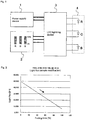
- Fig. 1 shows a first embodiment of the present invention.
- a LED illuminating device includes a power supply device 1, a controller 2, a LED lighting device 3, and a LED unit 4.
- the LED unit 4 includes LEDs of emission colors, red (R), green (G), and blue (B), and is able to emit light in various colors by adequately changing an emission intensity of each of LEDs, R, G, and B.
- the power supply device 1 is a power supply for driving the LED lighting device, the power supply being supplied at, for example, DC 30V.
- the controller 2 is composed of three sliding volume faders, and labels of red (R), green (G), and blue (B) are added to the respective faders.
- Outputs of the controller 2 are connected to the LED lighting device 3, and are configured so as to transmit positional scale information of the respective volume faders to the LED lighting device 3.
- the positional scale information of the respective volume faders are shown as fR, fG, and fB, and a minimum value of their possible values is 0 and a maximum value is 1.
- the LED lighting device 3 changes a lighting state of the LED unit 4 an the basis of the positional scale information of the volume faders from the controller 2.
- Luminance of the LEDs controlled by the LED lighting device 3 are shown as (pR, (pG, and (pB, and a minimum value of their possible values is 0 and a maximum value is 1.
- the white color can be certainly reproduced when fR, fG, and fB are equal to 1.
- another LED unit 4 also can be lighted in the white color by obtaining other kR, kG, and kB (coefficients specific to the LED unit).
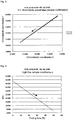
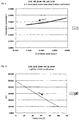
- Figs 2 and 3 show graphs obtained by calculating a synthetic light flux and a synthetic chromaticity in operating the volume faders in a case where unevenness of the respective LEDs show the values of the table 1.
- Figs. 4 and 5 show graphs obtained by calculating the synthetic light flux and the synthetic chromaticity in operating the volume faders in a case where the unevenness of the respective LEDs show the values of the table 2.
- the device since the device is configured to employ values obtained by multiplying indication values fR, fG, and fB of the volume faders of the controller 2 by the preliminarily-set constants kR, kG, and kB specific to the LED unit 4 as the lighting control values ⁇ R, ⁇ G, and ⁇ B of each LED, the low-cost LED illuminating device that reduces the color unevenness between the illumination devices despite unevenness of the LED unit 4 can be provided.
- the output voltage of the power supply device 1 is DC 30V in the configuration, however, other DC voltages and AC voltages may be employed.
- Means adapted to transmit information from the controller 2 to the LED lighting device 3 may be a digital Signal (the DMX signal, the PNM signal, and the like) and may be an analog signal (the DC voltage, the PWM signal, and the like).
- the lighting control means of the LED lighting device 3 may control the lighting by: changing a current passing through a LED load; and changing the duty of a pulsed load current.
- a technical idea of the present Invention can be arbitrarily applied if applied to light sources of different colors, and can provide the same effect also to unevenness of light sources such as an organic EL, laser light, and an incandescent light through Filter. It is the same with following each embodiment.
- a configuration according to a second embodiment of the present invention is the configuration of Fig. 1 same as that of first embodiment.
- the lighting control of the LED lighting device 3 is controlled an the Basis of following expressions.
- the max (a, b) is a function for showing the larger value, a or b.
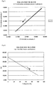
- Figs. 6 and 7 show graphs obtained, in a case of employing the control method, by calculating a synthetic light flux and a synthetic chromaticity in operating the volume faders in a case where unevenness of the respective LEDs show the values of the table 1.
- Figs. 8 and 9 show graphs obtained by calculating a synthetic light flux and a synthetic chromaticity in a pattern of different operation of the volume faders in a case where unevenness of the respective LEDs show the values of the table 1.
- the device since the device is configured to: calculate an amount of the light flux to be outputted according to the above-mentioned calculation expressions by using values obtained by multiplying indication values of the volume faders of the controller by the preliminarily-set constants specific to the LED unit; and employ the amount as a lighting control value of the LED, the low-cost LED illuminating device that reduces the color unevenness between the illumination devices despite unevenness of the LED unit 4 can be provided.
- the coefficient multiplied by the indication value of the volume fader is 1 in a case of setting the volume fader to be a single color, and thus the device is configured not to lower the light flux of the single color even when the LED is uneven.
- a configuration according to a third embodiment of the present invention is the configuration of Fig. 1 same as that of first embodiment.
- the lighting control of the LED lighting device 3 is controlled an the basis of the following expressions.
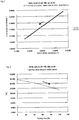
- Figs. 10 and Fig. 11 show graphs obtained, in the case of employing the control method, by calculating a synthetic light flux and a synthetic chromaticity in operating the volume faders in a case where unevenness of the respective LEDs show the values of the table 1.
- Figs. 12 and 13 show graphs obtained by calculating a synthetic light flux and a synthetic chromaticity in a pattern of different operation of the volume faders in a case where unevenness of the respective LEDs show the values of the table 1.
- the present embodiment has advantages that allow an intuitive operation for adjustment of the volume fader to facilitate a color matching.
- the device since the device is configured to: calculate an amount of the light flux to be outputted according to the above-mentioned calculation expressions by using values obtained by multiplying indication values of the volume faders of the controller by the preliminarily-set constants specific to the LED load; and employ the amount as the lighting control value of the LED, the low-cost LED illuminating device that reduces the color unevenness between the illumination devices despite unevenness of the LED load can be provided.
- the coefficient multiplied by the indication value of the volume fader is 1 in a case of setting the volume fader to be a single color, and thus the device is configured not to lower the light flux of the single color even when the LED is uneven.
- the characteristic since the characteristic has no changing point in operation of the volume fader and linearly changes, an intuitive operation is realized.
- a relationship between the operation of the volume fader and a fading time is described as a proportional relationship in the graph of the present embodiment, and a non-linear specific function (the Munsell curve, a 2.3th power curve, and the like) of time is generally used to smooth an appearance of light, however, when any relationship is employed as the relationship between the volume fader and the time, a same effect can be obtained regardless of a way of thinking of the present invention, and when there is no relationship between an actual Operation amount of the volume fader and a value of the volume fader, a same effect can be obtained.
- a LED mounting LEDs of three colors, RGB, in a singly package called 3-in-1 exists, and, in the LED, a current value able to flow when the LED is lighted in a single color is different from a current value able to flow when the three colors of RGB are lighted at the same time.
- the current value of the LED is adjusted according to the following expressions by using the luminance values ⁇ R, ⁇ G, and ⁇ B of the LEDs obtained by the calculation expressions of the above-mentioned embodiments, the light is naturally-dimmed in both of the light flux and the chromaticity.
- IRO, IGO, and IBO represent electric currents passing through each of the LEDs of R, G, and B to output ⁇ R, ⁇ G, and ⁇ B, respectively, and IR, IG, and IB represent current values adjusted for the 3-in-1 LED.
- the present invention can be applied to an LEDillumination device including an LED unit having four types of light colors, which can be knew by analogy from the above-mentioned first to third embodiments.
- Figs. 14 to 18 show schematic configurations of LED illuminating devices according to a fourth embodiment of the present invention.
- a subtle color matching can be carried out by a mechanistic operation to realize a control for reducing unevenness of colors between the LED illuminating devices.
- the light colors are adjusted by changing current values of the respective LEDs of R, G, and B, and in the case where the LEDs are fixed to have the identical position relationship, the mixing state of colors is sometimes uneven when a mixed light color, for example, an even white is represented, however, the mixing state of colors can be variously adjusted and an even mixed color can be represented by changing the configuration as shown in Figs. 14 to 18 .
- Figs. 14 to 18 are examples, and the present invention is not limited to these configurations. Though it is preferred to automatically adjust the color correction, means by manual adjustment may be employed.
- light outputs of R, G, and B are changed independently by the mechanistic operation, however, by simultaneously changing the respective current values of LEDs also as in the first to third embodiments, an optimum light color may be set by the current value and the changing means for configuration.
- an optimum light color may be set by the current value and the changing means for configuration.
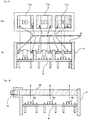
- Fig. 14 is characterized by including means adapted to adjust the synthetic color of outputted light by individually changing a height of each LED when the LEDs of R, G, and B are housed in one structure.
- the synthetic light color of the light output (for example, white) from the LED unit 4 is detected and the individual heights of the LEDs 4a, 4b, and 4c of R, G, and B are automatically or manually adjusted so that a predetermined light color is emitted.
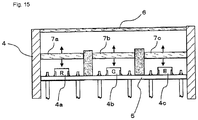
- Fig. 15 is characterized by including means adapted to adjust the synthetic color of outputted light by individually changing a height of each lens part provided to the LEDs of R, G, and B, respectively.
- the LEDs 4a, 4b, and 4c of R, G, and B are mounted an one piece of a rectangular LED substrate 5 as shown in Fig. 15 , which is configured so that a predetermined current value can pass through the LEDs 4a, 4b, and 4c of R, G, and B, respectively.
- a mechanism in which independent lens parts (panel parts) 7a, 7b, and 7c are provided an upper portions of the LEDs 4a, 4b, and 4c of R, G, and B, respectively, and their heights are independently varied up and down as shown by arrowed lines, respectively is included.
- the color unevenness of the LEDs 4a, 4b, and 4c of R, G, and B is adjusted to emit a predetermined light color by changing their transmittance through: detection and comparison of the light color with a predetermined light output (for example, white); and adjustment of the individual heights of the LEDs parts (panel parts) 7a, 7b, and 7c.
- a lens part having an uneven thickness is provided to an upper portion of a round-shaped LED unit mounting the LEDs of R, G, and B; and transmittance of lights from the respective LEDs are changed by rotating the lens part.
- the LEDs of R, G, and B are mounted an a round-shaped substrate 8, which is configured so that a predetermined current value can pass through the LEDs of R, G, and B, respectively, and a lens part 9 is provided to their upper portions.
- a thickness of the lens part 9 is not even, a lens thicknesses at the upper portions of the LEDs of R, G, and B are designed to be different from each other, and the lens part 9 is configured to be able to rotate.
- the symbol R represents a red LED
- the symbol G represents a green LED
- the symbol B represents a blue LED
- a number 10 represents a lens frame part.
- the synthetic light is adjusted to be the predetermined light color by rotating the lens part 9 to change transmittance of the respective lights of the LEDs of R, G, and B.
- Figs. 16 (b) and (c) illustrate as images that each of the lens thicknesses at the upper portions of the LEDs of R, G, and B changes when the lens part 9 rotates 180 degrees.
- each of the LEDs of R, G, and B is stored in a room with partitions; and means adapted to change apertures of aperture windows 11a, 11b, and 11c provided to their upper portions is included.
- the symbol R represents the red LED
- the symbol G represents the green LED
- the symbol B represents the blue LED.
- the LEDs of R, G, and B are mounted on the rectangular substrate 5, a structure able to house the LEDs of R, G, and B in rooms each individually having a window is employed, and a light color is adjusted by change areas of the aperture windows 11a, 11b, and 11c to change light outputs of the LEDs of R, G, and B, respectively.
- the synthetic light color is different from a predetermined light color due to the color unevenness of the LEDs of R, G, and B
- the synthetic light is adjusted to be the predetermined light color by changing the aperture areas of the aperture windows 11a, 11b, and 11c to adjust lights of the LEDs of R, G, and B.
- a lens part provided at an upper portion of the LEDs of R, G, and B as means adapted to adjust an emission amount includes a light guiding plate 12; and a color of the light guiding plate 12 is changed by using a second RGB light source 13 as a light source of the light guiding plate 12.
- the LEDs 4a, 4b, and 4c of R, G, and B are mounted on one piece of the substrate 5; the light guiding plate 12 is arranged at their upper portion; and the another second RGB light source 13 is additionally provided to the light guiding plate 12 to change a color of the light guiding plate 12.
- the second RGB light source 13 is, for example, an RGB bulb.
- the synthetic light is adjusted to be the predetermined light color by: changing a light color of the second RGB light source 13 to change the light color from the light guiding plate 12.
Landscapes
- Circuit Arrangement For Electric Light Sources In General (AREA)
- Led Device Packages (AREA)
Description
- The present invention relates to a LED illuminating device that employs a plurality of LEDs emitting different light colors as a light source and that has a function for changing a light color by dimming each of the LEDs.
- Japanese Unexamined Patent Publication No.
2001-93305 -
WO 2004/100611 A1 shows a device that is adapted to adjust the color output of multiple LEDs. A color mixer is provided in the light path of the emitted light. The power supplied to individual LEDs emitting light of different colors is controlled to achieve a precise color output. -
EP 1887 836 A2 refers to a bulb-like LED device that is suitable for different grid voltages (110 V / 60 Hz and 220 V / 50 Hz). A look up table is provided that correlates the input power parameters with LED output values for con-tolling the LEDs. -
US 2005/0253533 A1 shows a lighting device with LEDs emitting light with different colors. A processor is provided to control the LEDs to adjust various intensities of the different LEDs. - However, a conventional LED illuminating device has a problem where a same color cannot be obtained because of: unevenness of luminance of LEDs; and unevenness of emission colors of the LEDs themselves even in a case of lighting a plurality of LED illuminating devices in a same lighting state.
- An object of the present invention is to provide, at a low price, a LED illuminating device that reduces unevenness of the color even when the luminance of LEDs are uneven and the emission colors of the LEDs themselves are uneven.
- To solve the above-mentioned problems, an LED illuminating device according to
claim 1 is proposed. - According to the present invention, the invention is configured so that: a coefficient specified to a LED unit at which an emission color of the LED unit becomes a desired color can be set to a signal value of the controller preliminarily set as a standard; and the LED lighting device can adjust an emission amount of the LEDs of respective emission colors by using a value calculated from the specific coefficient, thus an LED illuminating device having a small color unevenness between the respective devices regardless of unevenness of luminance of the LEDs and emission colors of LEDs themselves can be provided.
-
Fig. 1 shows a first embodiment of the present invention. A LED illuminating device according to the present embodiment includes apower supply device 1, acontroller 2, a LED lighting device 3, and aLED unit 4. TheLED unit 4 includes LEDs of emission colors, red (R), green (G), and blue (B), and is able to emit light in various colors by adequately changing an emission intensity of each of LEDs, R, G, and B. - The
power supply device 1 is a power supply for driving the LED lighting device, the power supply being supplied at, for example, DC 30V. Thecontroller 2 is composed of three sliding volume faders, and labels of red (R), green (G), and blue (B) are added to the respective faders. Outputs of thecontroller 2 are connected to the LED lighting device 3, and are configured so as to transmit positional scale information of the respective volume faders to the LED lighting device 3. The positional scale information of the respective volume faders are shown as fR, fG, and fB, and a minimum value of their possible values is 0 and a maximum value is 1. The LED lighting device 3 changes a lighting state of theLED unit 4 an the basis of the positional scale information of the volume faders from thecontroller 2. Luminance of the LEDs controlled by the LED lighting device 3 are shown as (pR, (pG, and (pB, and a minimum value of their possible values is 0 and a maximum value is 1. - Now, regarding
certain LED unit 4, it is assumed that the luminance ϕR, ϕG, and ϕB at which the white (for example, X = 0.281 and Y = 0.287 in the chromaticity coordinates) and a maximum emission intensity is obtained by adjusting the LED lighting device 3 are ϕR0, ϕG0, and ϕB0, respectively. - Here, consider the following coefficients kR, kG, and kB,


- And, a conventional control of the LED lighting device 3 is configured to be controlled in accordance with following expressions,


- Due to the lighting control carried out in the above-mentioned manner, the white color can be certainly reproduced when fR, fG, and fB are equal to 1. In the similar manner, another
LED unit 4 also can be lighted in the white color by obtaining other kR, kG, and kB (coefficients specific to the LED unit).[Table 1] Light source 1Light source 2Light source 3 (R) (G) (B) Chromaticity x of light source 0.6850 0.1900 0.1300 Chromaticity y of light source 0.3050 0.6900 0.0750 Chromaticity z of light source 20.00 30.00 10.00 kR = 0.6408, kG = 1.0000, and kB = 0.6467 [Table 2] Light source 1Light source 2Light source 3 (R) (G) (B) Chromaticity x of light source 0.6850 0.1900 0.1370 Chromaticity y of light source 0.3050 0.6900 0.0370 Chromaticity z of light source 20.00 30.00 10.00 kR = 0.5443, kG = 1.0000, and kB = 0.2688 -
Figs 2 and3 show graphs obtained by calculating a synthetic light flux and a synthetic chromaticity in operating the volume faders in a case where unevenness of the respective LEDs show the values of the table 1. In addition,Figs. 4 and5 show graphs obtained by calculating the synthetic light flux and the synthetic chromaticity in operating the volume faders in a case where the unevenness of the respective LEDs show the values of the table 2. InFigs. 2 to 5 , it is assumed that the values of the volume faders in each case linearly change from fR=1.00, fG=1.00, and fB=1.00 to fR=0.00, fG=0.00, and fB=1.00. - Comparing
Fig. 3 withFig. 5 , it can be found that the chromaticity coordinates of a single color after the fading show different colors because of the unevenness of each LED, however, the chromaticity coordinates at the beginning of the fading are X=0.281 and Y=0.287 to show the same color. - According to the conventional control of the first embodiment, since the device is configured to employ values obtained by multiplying indication values fR, fG, and fB of the volume faders of the
controller 2 by the preliminarily-set constants kR, kG, and kB specific to theLED unit 4 as the lighting control values ϕR, ϕG, and ϕB of each LED, the low-cost LED illuminating device that reduces the color unevenness between the illumination devices despite unevenness of theLED unit 4 can be provided. - Meanwhile, the output voltage of the
power supply device 1 is DC 30V in the configuration, however, other DC voltages and AC voltages may be employed. Means adapted to transmit information from thecontroller 2 to the LED lighting device 3 may be a digital Signal (the DMX signal, the PNM signal, and the like) and may be an analog signal (the DC voltage, the PWM signal, and the like). The lighting control means of the LED lighting device 3 may control the lighting by: changing a current passing through a LED load; and changing the duty of a pulsed load current. In addition, a technical idea of the present Invention can be arbitrarily applied if applied to light sources of different colors, and can provide the same effect also to unevenness of light sources such as an organic EL, laser light, and an incandescent light through Filter. It is the same with following each embodiment. - A configuration according to a second embodiment of the present invention is the configuration of
Fig. 1 same as that of first embodiment. However, the lighting control of the LED lighting device 3 is controlled an the Basis of following expressions.


-
Figs. 6 and7 show graphs obtained, in a case of employing the control method, by calculating a synthetic light flux and a synthetic chromaticity in operating the volume faders in a case where unevenness of the respective LEDs show the values of the table 1. InFigs. 6 and7 , it is assumed that the values of the volume faders linearly change from fR=1.00, fG=1.00, and fB=1.00 to fR=0.00, fG=0.00, and fB=1.00. - Comparing
Fig. 6 withFig. 2 , it can be found that there is a difference between the light fluxes when a fading time reaches a rate of 100%. The light flux ofFig. 6 according to the present embodiment is higher than the other one, and accordingly it is found that a performance of the LED can be sufficiently given. Additionally, according to comparison ofFig. 3 withFig. 7 , it can be confirmed that there is no difference in a chromaticity range that can be reproduced. -
Figs. 8 and9 show graphs obtained by calculating a synthetic light flux and a synthetic chromaticity in a pattern of different operation of the volume faders in a case where unevenness of the respective LEDs show the values of the table 1. InFigs. 8 and9 , it is assumed that the values of the volume faders linearly change from fR=1.00, fG=0.50, and fB=1.00 to fR=0.00, fG=0.50, and fB=1.00. - According to the present embodiment, since the device is configured to: calculate an amount of the light flux to be outputted according to the above-mentioned calculation expressions by using values obtained by multiplying indication values of the volume faders of the controller by the preliminarily-set constants specific to the LED unit; and employ the amount as a lighting control value of the LED, the low-cost LED illuminating device that reduces the color unevenness between the illumination devices despite unevenness of the
LED unit 4 can be provided. Additionally, in the present embodiment, the coefficient multiplied by the indication value of the volume fader is 1 in a case of setting the volume fader to be a single color, and thus the device is configured not to lower the light flux of the single color even when the LED is uneven. - A configuration according to a third embodiment of the present invention is the configuration of
Fig. 1 same as that of first embodiment. However, the lighting control of the LED lighting device 3 is controlled an the basis of the following expressions.


-
Figs. 10 andFig. 11 show graphs obtained, in the case of employing the control method, by calculating a synthetic light flux and a synthetic chromaticity in operating the volume faders in a case where unevenness of the respective LEDs show the values of the table 1. InFigs. 10 and11 , it is assumed that the values of the volume faders linearly change from fR = 1.00, fG = 1.00, and fB = 1.00 to fR = 0.00, fG = 0.00, and fB = 1.00. - Comparing
Fig. 10 withFig. 2 , it can be found that there is a difference between the light fluxes when the fading time reaches a rate of 100%. The light flux ofFig. 10 according to the present embodiment is higher than the other one, and accordingly it is found that a performance of the LED can be sufficiently given. Additionally, according to comparison ofFig. 3 withFig. 11 , it can be confirmed that there is no difference in a chromaticity range that can be reproduced. -
Figs. 12 and13 show graphs obtained by calculating a synthetic light flux and a synthetic chromaticity in a pattern of different operation of the volume faders in a case where unevenness of the respective LEDs show the values of the table 1. InFigs. 12 and13 , it is assumed that the values of the volume faders linearly change from fR=1.00, fG=0.50, and fB=1.00 to fR=0.00, fG=0.50, and fB=1.00. - Comparing
Fig. 8 withFig. 12 and comparingFig. 9 withFig. 13 , a bending point is generated in the fading period inFigs. 8 and9 , however, the bending point is not generated inFigs. 12 and13 . Accordingly, as compared to the second embodiment, the present embodiment has advantages that allow an intuitive operation for adjustment of the volume fader to facilitate a color matching. - According to the present embodiment, since the device is configured to: calculate an amount of the light flux to be outputted according to the above-mentioned calculation expressions by using values obtained by multiplying indication values of the volume faders of the controller by the preliminarily-set constants specific to the LED load; and employ the amount as the lighting control value of the LED, the low-cost LED illuminating device that reduces the color unevenness between the illumination devices despite unevenness of the LED load can be provided. In the present embodiment, the coefficient multiplied by the indication value of the volume fader is 1 in a case of setting the volume fader to be a single color, and thus the device is configured not to lower the light flux of the single color even when the LED is uneven. In addition, since the characteristic has no changing point in operation of the volume fader and linearly changes, an intuitive operation is realized.
- Meanwhile, to simplify the description, a relationship between the operation of the volume fader and a fading time is described as a proportional relationship in the graph of the present embodiment, and a non-linear specific function (the Munsell curve, a 2.3th power curve, and the like) of time is generally used to smooth an appearance of light, however, when any relationship is employed as the relationship between the volume fader and the time, a same effect can be obtained regardless of a way of thinking of the present invention, and when there is no relationship between an actual Operation amount of the volume fader and a value of the volume fader, a same effect can be obtained.
- In addition, a LED mounting LEDs of three colors, RGB, in a singly package called 3-in-1 exists, and, in the LED, a current value able to flow when the LED is lighted in a single color is different from a current value able to flow when the three colors of RGB are lighted at the same time. In that case, when the current value of the LED is adjusted according to the following expressions by using the luminance values ϕR, ϕG, and ϕB of the LEDs obtained by the calculation expressions of the above-mentioned embodiments, the light is naturally-dimmed in both of the light flux and the chromaticity.


- In the above-mentioned expressions, IRO, IGO, and IBO represent electric currents passing through each of the LEDs of R, G, and B to output ϕR, ϕG, and ϕB, respectively, and IR, IG, and IB represent current values adjusted for the 3-in-1 LED.
- It is obvious that the present invention can be applied to an LEDillumination device including an LED unit having four types of light colors, which can be knew by analogy from the above-mentioned first to third embodiments.
-
Figs. 14 to 18 show schematic configurations of LED illuminating devices according to a fourth embodiment of the present invention. In the present embodiment, in the case where a plurality of the LED illuminating devices are controlled, a subtle color matching can be carried out by a mechanistic operation to realize a control for reducing unevenness of colors between the LED illuminating devices. - In the first to third embodiments, the light colors are adjusted by changing current values of the respective LEDs of R, G, and B, and in the case where the LEDs are fixed to have the identical position relationship, the mixing state of colors is sometimes uneven when a mixed light color, for example, an even white is represented, however, the mixing state of colors can be variously adjusted and an even mixed color can be represented by changing the configuration as shown in
Figs. 14 to 18 . - The configurations shown in
Figs. 14 to 18 are examples, and the present invention is not limited to these configurations. Though it is preferred to automatically adjust the color correction, means by manual adjustment may be employed. - Additionally, in the present embodiment, light outputs of R, G, and B are changed independently by the mechanistic operation, however, by simultaneously changing the respective current values of LEDs also as in the first to third embodiments, an optimum light color may be set by the current value and the changing means for configuration. Concrete examples of the mechanistic color correction means mounted an each LED illuminating device will be explained below.
- The example of
Fig. 14 is characterized by including means adapted to adjust the synthetic color of outputted light by individually changing a height of each LED when the LEDs of R, G, and B are housed in one structure. - As shown in
Fig. 14 , a mechanism in whichLEDs individual substrates substrates rectangular LED unit 4, and the substrates independently move up and down as shown by arrowed lines, respectively is included. Since relative distances from theLEDs lens 6 become variable in this manner, transmittance of the lights can be variable. In the case where a predetermined current value passes through each of theLEDs LED unit 4 is detected and the individual heights of theLEDs - The example of
Fig. 15 is characterized by including means adapted to adjust the synthetic color of outputted light by individually changing a height of each lens part provided to the LEDs of R, G, and B, respectively. - The
LEDs rectangular LED substrate 5 as shown inFig. 15 , which is configured so that a predetermined current value can pass through theLEDs LEDs LEDs - The example of
Fig. 16 is characterized in that: a lens part having an uneven thickness is provided to an upper portion of a round-shaped LED unit mounting the LEDs of R, G, and B; and transmittance of lights from the respective LEDs are changed by rotating the lens part. - As shown in
Fig. 16(a) , the LEDs of R, G, and B are mounted an a round-shapedsubstrate 8, which is configured so that a predetermined current value can pass through the LEDs of R, G, and B, respectively, and a lens part 9 is provided to their upper portions. A thickness of the lens part 9 is not even, a lens thicknesses at the upper portions of the LEDs of R, G, and B are designed to be different from each other, and the lens part 9 is configured to be able to rotate. In the drawing, the symbol R represents a red LED, the symbol G represents a green LED, the symbol B represents a blue LED, and anumber 10 represents a lens frame part. - In the case where the synthetic light color is different from a predetermined light color due to the color unevenness of the LEDs of R, G, and B, the synthetic light is adjusted to be the predetermined light color by rotating the lens part 9 to change transmittance of the respective lights of the LEDs of R, G, and B.
-
Figs. 16 (b) and (c) illustrate as images that each of the lens thicknesses at the upper portions of the LEDs of R, G, and B changes when the lens part 9 rotates 180 degrees. - The example of
Fig. 17 is characterized in that: each of the LEDs of R, G, and B is stored in a room with partitions; and means adapted to change apertures ofaperture windows - As shown in
Fig. 17 , the LEDs of R, G, and B are mounted on therectangular substrate 5, a structure able to house the LEDs of R, G, and B in rooms each individually having a window is employed, and a light color is adjusted by change areas of theaperture windows aperture windows - The example of
Fig. 18 is characterized in that: a lens part provided at an upper portion of the LEDs of R, G, and B as means adapted to adjust an emission amount includes alight guiding plate 12; and a color of thelight guiding plate 12 is changed by using a secondRGB light source 13 as a light source of thelight guiding plate 12. - As shown in
Fig. 18 , a configuration where: theLEDs substrate 5; thelight guiding plate 12 is arranged at their upper portion; and the another secondRGB light source 13 is additionally provided to thelight guiding plate 12 to change a color of thelight guiding plate 12. The secondRGB light source 13 is, for example, an RGB bulb. Also in the present example, in the case where the synthetic light color is different from a predetermined light color due to the color unevenness of the LEDs of R, G, and B, the synthetic light is adjusted to be the predetermined light color by: changing a light color of the secondRGB light source 13 to change the light color from thelight guiding plate 12. -
- [
Fig. 1] Fig. 1 is a block diagram showing a configuration according to a first embodiment of the present invention. - [
Fig. 2] Fig. 2 is an explanation view showing a synthetic light flux according to the first embodiment of the present invention. - [
Fig. 3] Fig. 3 is an explanation view showing a synthetic chromaticity according to the first embodiment of the present invention. - [
Fig. 4] Fig. 4 is an explanation view showing the synthetic light flux according to the first embodiment of the present invention. - [
Fig. 5] Fig. 5 is an explanation view showing the synthetic chromaticity according to the first embodiment of the present invention. - [
Fig. 6] Fig. 6 is an explanation view showing a synthetic light flux according to a second embodiment of the present invention. - [
Fig. 7] Fig. 7 is an explanation view showing a synthetic chromaticity according to the second embodiment of the present invention. - [
Fig. 8] Fig. 8 is an explanation view showing the synthetic light flux according to the second embodiment of the present invention. - [
Fig. 9] Fig. 9 is an explanation view showing the synthetic chromaticity according to the second embodiment of the present invention. - [
Fig. 10] Fig. 10 is an explanation view showing a synthetic light flux according to a third embodiment of the present invention. - [
Fig. 11] Fig. 11 is an explanation view showing a synthetic chromaticity according to the third embodiment of the present invention. - [
Fig. 12] Fig. 12 is an explanation view showing the synthetic light flux according to the third embodiment of the present invention - [
Fig. 13] Fig. 13 is an explanation view showing the synthetic chromaticity according to the third embodiment of the present invention. - [
Fig. 14] Fig. 14 is a cross-section view showing a first configuration example of a LED illuminating device according to a fourth embodiment of the present invention. - [
Fig. 15] Fig. 15 is a cross-section view showing a second configuration example of the LED illuminating device according to the fourth embodiment of the present invention. - [
Fig. 16] Fig. 16 is a view showing a third configuration example of the LED illuminating device according to the fourth embodiment of the present invention, and (a) is a top view and (b) and (c) are cross-section views. - [
Fig. 17] Fig. 17 is a view showing a fourth configuration example of the LED illuminating device according to the fourth embodiment of the present invention, and (a) is a top view and (b) is a cross-section view. - [
Fig. 18] Fig. 18 is a cross-section view showing a fifth configuration example of the LED illuminating device according to the fourth embodiment of the present invention. -
- 1 Power supply device
- 2 Controller
- 3 LED lighting device
- 4 LED unit
Claims (7)
- An LED illuminating device comprising: a power source device (1); a controller (2); an LED lighting device (3); and an LED unit (4) that contains LEDs (4a, 4b, 4c) emitting light at a red, blue and green emission color (R, G, B) and that is configured so as to: mix the emitted red, blue and green light of the respective LEDs (4a, 4b, 4c) at an arbitrary proportion; and set the emitted red, blue and green light in an arbitrary color mixture proportion on the basis of dimming signals (fR, fG, fB) for each of the red, blue and green light (R, G, B) from the controller (2), wherein
the LED illuminating device is configured so that:specific coefficients (kR, kG, kB) for the red, blue and green light (R, G, B) respectively of the LED unit (4) at which the light emitted by the LED unit (4) becomes a predetermined default color (X, Y) in the X-Y-chromaticity diagram are set to a predetermined signal value (ϕR0, ϕG0, ϕB0) respectively; and the LED lighting device is configured to control an emission amount of the LEDs (4a, 4b, 4c) by using a signal values (ϕR, ϕG, ϕB) for the red, blue and green light (R, G, B) respectively calculated by one of the following calculation expressions:(1)

 (2)wherein

 ϕR is the signal value for the red light (R),ϕG is the signal value for the green light (G),ϕB is the signal value for the blue light (B),fR is the dimming signal for the red light (R),fG is the dimming signal for the green light (G),fB is the dimming signal for the blue light (B),kR is the specific coefficient for the red light (R), kG is the specific coefficient for the green light (G) andkB is the specific coefficient for the blue light (B).
 - The LED illuminating device according to claim 1, wherein
the LED unit (4) incorporating LEDs (4a, 4b, 4c) of a plurality of emission colors (R, G, B) includes a mechanism for individually adjusting the emission amounts of the respective LEDs (4a, 4b, 4c) in order to adjust the light emission color to a predetermined color. - The LED illuminating device according to claim 2, wherein
the mechanism contains individual substrates (5a, 5b, 5c) on which the LEDs (4a, 4b, 4c) having different light emission colors (R, G, B) are mounted respectively, the substrates (5a, 5b, 5c) are incorporated into the rectangular LED unit (4), and the substrates 5a, 5b, 5c) are configured to be independently movable up and down respectively to adjust relative distances between a respective LED (4a, 4b, 4c) and a lens (6) of the LED unit (4). - The LED illuminating device according to claim 2, wherein
the LEDs (4a, 4b, 4c) having different light emission colors (R, G, B) are mounted on one piece of a rectangular LED substrate (5),
the mechanism contains independent lens parts (7a, 7b, 7c) above the LEDs (4a, 4b, 4c) respectively, and are configured to be independently movable up and down respectively to adjust relative distances between the LEDs (4a, 4b, 4c) and the respective lens part (7a, 7b, 7c). - The LED illuminating device according to claim 2, wherein
the mechanism contains a rotatable lens part (9) having an uneven thickness that is provided above a round-shaped substrate (8) on which the LEDs (4a, 4b, 4c) having different light emission colors (R, G, B) are mounted. - The LED illuminating device according to claim 2, wherein
each of the LEDs (4a, 4b, 4c) having different light emission colors (R, G, B) is stored in one of a plurality of partitions of a room, each partition having a respective window (11a, 11b, 11c) above the contained LED (4a, 4b, 4c);
the mechanism contains means adapted to change the size of the respective windows (11a, 11b, 11c) individually. - The LED illuminating device according to claim 2, wherein
the mechanism contains a lens part provided above the LEDs (4a, 4b, 4c) having different light emission colors (R, G, B);
the lens part (12) including a light guiding plate (12) and a second RGB light source (13) adapted to emit light in the light guiding plate (12) to change the color of the light guiding plate (12).
Applications Claiming Priority (1)
| Application Number | Priority Date | Filing Date | Title |
|---|---|---|---|
| JP2008165056A JP5204563B2 (en) | 2008-06-24 | 2008-06-24 | LED lighting device |
Publications (3)
| Publication Number | Publication Date |
|---|---|
| EP2139296A2 EP2139296A2 (en) | 2009-12-30 |
| EP2139296A3 EP2139296A3 (en) | 2015-06-03 |
| EP2139296B1 true EP2139296B1 (en) | 2018-02-21 |
Family
ID=41119650
Family Applications (1)
| Application Number | Title | Priority Date | Filing Date |
|---|---|---|---|
| EP09163665.4A Not-in-force EP2139296B1 (en) | 2008-06-24 | 2009-06-24 | LED illuminating device |
Country Status (3)
| Country | Link |
|---|---|
| US (1) | US8143809B2 (en) |
| EP (1) | EP2139296B1 (en) |
| JP (1) | JP5204563B2 (en) |
Families Citing this family (3)
| Publication number | Priority date | Publication date | Assignee | Title |
|---|---|---|---|---|
| CN103688593B (en) * | 2011-07-26 | 2016-08-17 | 皇家飞利浦有限公司 | current determination device |
| US9386665B2 (en) | 2013-03-14 | 2016-07-05 | Honeywell International Inc. | System for integrated lighting control, configuration, and metric tracking from multiple locations |
| US10772173B1 (en) * | 2019-08-21 | 2020-09-08 | Electronic Theatre Controls, Inc. | Systems, methods, and devices for controlling one or more LED light fixtures |
Family Cites Families (14)
| Publication number | Priority date | Publication date | Assignee | Title |
|---|---|---|---|---|
| JP2001093305A (en) | 1999-09-28 | 2001-04-06 | Toyoda Gosei Co Ltd | Lighting equipment |
| PT1422975E (en) * | 2000-04-24 | 2010-07-09 | Philips Solid State Lighting | Light-emitting diode based product |
| US7358679B2 (en) * | 2002-05-09 | 2008-04-15 | Philips Solid-State Lighting Solutions, Inc. | Dimmable LED-based MR16 lighting apparatus and methods |
| US7615939B2 (en) * | 2003-03-17 | 2009-11-10 | C&D Zodiac, Inc. | Spectrally calibratable multi-element RGB LED light source |
| WO2004100611A1 (en) * | 2003-05-06 | 2004-11-18 | Ilumera Group Ag | Led lighting module and system |
| JP2006135006A (en) * | 2004-11-04 | 2006-05-25 | Sanyo Electric Co Ltd | Light emitting element |
| JP4826124B2 (en) * | 2005-04-15 | 2011-11-30 | 株式会社ニコン | Position measuring device |
| EP2372609A3 (en) * | 2005-05-20 | 2011-11-30 | Samsung Electronics Co., Ltd. | Multiprimary color subpixel rendering with metameric filtering |
| WO2007019663A1 (en) * | 2005-08-17 | 2007-02-22 | Tir Technology Lp | Digitally controlled luminaire system |
| JP2008135220A (en) * | 2006-11-27 | 2008-06-12 | M & S Fine Tec Kk | Backlight control system for liquid crystal display device, liquid crystal display device, LED light source, and backlight control method for liquid crystal display device |
| US20080180414A1 (en) * | 2007-01-30 | 2008-07-31 | Kai Ming Fung | Method and apparatus for controlling light emitting diode |
| KR101494320B1 (en) * | 2007-10-05 | 2015-02-23 | 삼성디스플레이 주식회사 | Backlight assembly and display device having the same |
| WO2009113055A2 (en) * | 2008-03-13 | 2009-09-17 | Microsemi Corp. - Analog Mixed Signal Group, Ltd. | A color controller for a luminaire |
| JP2009282187A (en) * | 2008-05-21 | 2009-12-03 | Renesas Technology Corp | Liquid crystal driving device |
-
2008
- 2008-06-24 JP JP2008165056A patent/JP5204563B2/en not_active Expired - Fee Related
-
2009
- 2009-06-24 US US12/490,556 patent/US8143809B2/en not_active Expired - Fee Related
- 2009-06-24 EP EP09163665.4A patent/EP2139296B1/en not_active Not-in-force
Non-Patent Citations (1)
| Title |
|---|
| None * |
Also Published As
| Publication number | Publication date |
|---|---|
| EP2139296A2 (en) | 2009-12-30 |
| EP2139296A3 (en) | 2015-06-03 |
| US20100019691A1 (en) | 2010-01-28 |
| JP5204563B2 (en) | 2013-06-05 |
| JP2010009790A (en) | 2010-01-14 |
| US8143809B2 (en) | 2012-03-27 |
Similar Documents
| Publication | Publication Date | Title |
|---|---|---|
| US11172558B2 (en) | Dim-to-warm LED circuit | |
| US20210160981A1 (en) | Systems and methods for providing color management control in a lighting panel | |
| EP1440604B1 (en) | Led control apparatus | |
| JP4785931B2 (en) | System and method for calibrating a solid state lighting panel | |
| US8766555B2 (en) | Tunable white color methods and uses thereof | |
| US20100072901A1 (en) | Method and driver for determining drive values for driving a lighting device | |
| US20140055038A1 (en) | Device and Method for Generating Light of a Predetermined Spectrum with at Least Four Differently Colored Light Sources | |
| JP5538078B2 (en) | LED power supply | |
| US20130134901A1 (en) | Driving apparatus for light emitting diode and control method thereof | |
| US11357086B2 (en) | Apparatus, system, and method of calibrating and driving LED light sources | |
| US11076461B2 (en) | User control modality for LED color tuning | |
| EP2139296B1 (en) | LED illuminating device | |
| KR102488473B1 (en) | Dim-to-warm LED circuit | |
| US11013077B2 (en) | LED driver dimming | |
| CA3020493C (en) | Led driver dimming | |
| KR20190025582A (en) | Driving apparatus for light emitting and controlling method thereof |
Legal Events
| Date | Code | Title | Description |
|---|---|---|---|
| PUAI | Public reference made under article 153(3) epc to a published international application that has entered the european phase |
Free format text: ORIGINAL CODE: 0009012 |
|
| AK | Designated contracting states |
Kind code of ref document: A2 Designated state(s): AT BE BG CH CY CZ DE DK EE ES FI FR GB GR HR HU IE IS IT LI LT LU LV MC MK MT NL NO PL PT RO SE SI SK TR |
|
| RAP1 | Party data changed (applicant data changed or rights of an application transferred) |
Owner name: PANASONIC CORPORATION |
|
| RAP1 | Party data changed (applicant data changed or rights of an application transferred) |
Owner name: PANASONIC INTELLECTUAL PROPERTY MANAGEMENT CO., LT |
|
| PUAL | Search report despatched |
Free format text: ORIGINAL CODE: 0009013 |
|
| AK | Designated contracting states |
Kind code of ref document: A3 Designated state(s): AT BE BG CH CY CZ DE DK EE ES FI FR GB GR HR HU IE IS IT LI LT LU LV MC MK MT NL NO PL PT RO SE SI SK TR |
|
| RIC1 | Information provided on ipc code assigned before grant |
Ipc: H05B 37/02 20060101ALI20150429BHEP Ipc: H05B 33/08 20060101AFI20150429BHEP |
|
| 17P | Request for examination filed |
Effective date: 20150623 |
|
| RBV | Designated contracting states (corrected) |
Designated state(s): AT BE BG CH CY CZ DE DK EE ES FI FR GB GR HR HU IE IS IT LI LT LU LV MC MK MT NL NO PL PT RO SE SI SK TR |
|
| 17Q | First examination report despatched |
Effective date: 20160623 |
|
| GRAP | Despatch of communication of intention to grant a patent |
Free format text: ORIGINAL CODE: EPIDOSNIGR1 |
|
| STAA | Information on the status of an ep patent application or granted ep patent |
Free format text: STATUS: GRANT OF PATENT IS INTENDED |
|
| INTG | Intention to grant announced |
Effective date: 20171117 |
|
| GRAS | Grant fee paid |
Free format text: ORIGINAL CODE: EPIDOSNIGR3 |
|
| GRAA | (expected) grant |
Free format text: ORIGINAL CODE: 0009210 |
|
| STAA | Information on the status of an ep patent application or granted ep patent |
Free format text: STATUS: THE PATENT HAS BEEN GRANTED |
|
| AK | Designated contracting states |
Kind code of ref document: B1 Designated state(s): AT BE BG CH CY CZ DE DK EE ES FI FR GB GR HR HU IE IS IT LI LT LU LV MC MK MT NL NO PL PT RO SE SI SK TR |
|
| REG | Reference to a national code |
Ref country code: GB Ref legal event code: FG4D |
|
| REG | Reference to a national code |
Ref country code: CH Ref legal event code: EP |
|
| REG | Reference to a national code |
Ref country code: AT Ref legal event code: REF Ref document number: 973073 Country of ref document: AT Kind code of ref document: T Effective date: 20180315 |
|
| REG | Reference to a national code |
Ref country code: IE Ref legal event code: FG4D |
|
| REG | Reference to a national code |
Ref country code: DE Ref legal event code: R096 Ref document number: 602009050811 Country of ref document: DE |
|
| REG | Reference to a national code |
Ref country code: NL Ref legal event code: MP Effective date: 20180221 |
|
| REG | Reference to a national code |
Ref country code: LT Ref legal event code: MG4D |
|
| REG | Reference to a national code |
Ref country code: AT Ref legal event code: MK05 Ref document number: 973073 Country of ref document: AT Kind code of ref document: T Effective date: 20180221 |
|
| PG25 | Lapsed in a contracting state [announced via postgrant information from national office to epo] |
Ref country code: CY Free format text: LAPSE BECAUSE OF FAILURE TO SUBMIT A TRANSLATION OF THE DESCRIPTION OR TO PAY THE FEE WITHIN THE PRESCRIBED TIME-LIMIT Effective date: 20180221 Ref country code: LT Free format text: LAPSE BECAUSE OF FAILURE TO SUBMIT A TRANSLATION OF THE DESCRIPTION OR TO PAY THE FEE WITHIN THE PRESCRIBED TIME-LIMIT Effective date: 20180221 Ref country code: NL Free format text: LAPSE BECAUSE OF FAILURE TO SUBMIT A TRANSLATION OF THE DESCRIPTION OR TO PAY THE FEE WITHIN THE PRESCRIBED TIME-LIMIT Effective date: 20180221 Ref country code: FI Free format text: LAPSE BECAUSE OF FAILURE TO SUBMIT A TRANSLATION OF THE DESCRIPTION OR TO PAY THE FEE WITHIN THE PRESCRIBED TIME-LIMIT Effective date: 20180221 Ref country code: ES Free format text: LAPSE BECAUSE OF FAILURE TO SUBMIT A TRANSLATION OF THE DESCRIPTION OR TO PAY THE FEE WITHIN THE PRESCRIBED TIME-LIMIT Effective date: 20180221 Ref country code: NO Free format text: LAPSE BECAUSE OF FAILURE TO SUBMIT A TRANSLATION OF THE DESCRIPTION OR TO PAY THE FEE WITHIN THE PRESCRIBED TIME-LIMIT Effective date: 20180521 Ref country code: HR Free format text: LAPSE BECAUSE OF FAILURE TO SUBMIT A TRANSLATION OF THE DESCRIPTION OR TO PAY THE FEE WITHIN THE PRESCRIBED TIME-LIMIT Effective date: 20180221 |
|
| PG25 | Lapsed in a contracting state [announced via postgrant information from national office to epo] |
Ref country code: SE Free format text: LAPSE BECAUSE OF FAILURE TO SUBMIT A TRANSLATION OF THE DESCRIPTION OR TO PAY THE FEE WITHIN THE PRESCRIBED TIME-LIMIT Effective date: 20180221 Ref country code: BG Free format text: LAPSE BECAUSE OF FAILURE TO SUBMIT A TRANSLATION OF THE DESCRIPTION OR TO PAY THE FEE WITHIN THE PRESCRIBED TIME-LIMIT Effective date: 20180521 Ref country code: AT Free format text: LAPSE BECAUSE OF FAILURE TO SUBMIT A TRANSLATION OF THE DESCRIPTION OR TO PAY THE FEE WITHIN THE PRESCRIBED TIME-LIMIT Effective date: 20180221 Ref country code: LV Free format text: LAPSE BECAUSE OF FAILURE TO SUBMIT A TRANSLATION OF THE DESCRIPTION OR TO PAY THE FEE WITHIN THE PRESCRIBED TIME-LIMIT Effective date: 20180221 Ref country code: GR Free format text: LAPSE BECAUSE OF FAILURE TO SUBMIT A TRANSLATION OF THE DESCRIPTION OR TO PAY THE FEE WITHIN THE PRESCRIBED TIME-LIMIT Effective date: 20180522 |
|
| PG25 | Lapsed in a contracting state [announced via postgrant information from national office to epo] |
Ref country code: PL Free format text: LAPSE BECAUSE OF FAILURE TO SUBMIT A TRANSLATION OF THE DESCRIPTION OR TO PAY THE FEE WITHIN THE PRESCRIBED TIME-LIMIT Effective date: 20180221 Ref country code: RO Free format text: LAPSE BECAUSE OF FAILURE TO SUBMIT A TRANSLATION OF THE DESCRIPTION OR TO PAY THE FEE WITHIN THE PRESCRIBED TIME-LIMIT Effective date: 20180221 Ref country code: IT Free format text: LAPSE BECAUSE OF FAILURE TO SUBMIT A TRANSLATION OF THE DESCRIPTION OR TO PAY THE FEE WITHIN THE PRESCRIBED TIME-LIMIT Effective date: 20180221 Ref country code: EE Free format text: LAPSE BECAUSE OF FAILURE TO SUBMIT A TRANSLATION OF THE DESCRIPTION OR TO PAY THE FEE WITHIN THE PRESCRIBED TIME-LIMIT Effective date: 20180221 |
|
| REG | Reference to a national code |
Ref country code: DE Ref legal event code: R097 Ref document number: 602009050811 Country of ref document: DE |
|
| PG25 | Lapsed in a contracting state [announced via postgrant information from national office to epo] |
Ref country code: SK Free format text: LAPSE BECAUSE OF FAILURE TO SUBMIT A TRANSLATION OF THE DESCRIPTION OR TO PAY THE FEE WITHIN THE PRESCRIBED TIME-LIMIT Effective date: 20180221 Ref country code: DK Free format text: LAPSE BECAUSE OF FAILURE TO SUBMIT A TRANSLATION OF THE DESCRIPTION OR TO PAY THE FEE WITHIN THE PRESCRIBED TIME-LIMIT Effective date: 20180221 Ref country code: CZ Free format text: LAPSE BECAUSE OF FAILURE TO SUBMIT A TRANSLATION OF THE DESCRIPTION OR TO PAY THE FEE WITHIN THE PRESCRIBED TIME-LIMIT Effective date: 20180221 |
|
| PLBE | No opposition filed within time limit |
Free format text: ORIGINAL CODE: 0009261 |
|
| STAA | Information on the status of an ep patent application or granted ep patent |
Free format text: STATUS: NO OPPOSITION FILED WITHIN TIME LIMIT |
|
| 26N | No opposition filed |
Effective date: 20181122 |
|
| REG | Reference to a national code |
Ref country code: CH Ref legal event code: PL |
|
| GBPC | Gb: european patent ceased through non-payment of renewal fee |
Effective date: 20180624 |
|
| PG25 | Lapsed in a contracting state [announced via postgrant information from national office to epo] |
Ref country code: SI Free format text: LAPSE BECAUSE OF FAILURE TO SUBMIT A TRANSLATION OF THE DESCRIPTION OR TO PAY THE FEE WITHIN THE PRESCRIBED TIME-LIMIT Effective date: 20180221 |
|
| REG | Reference to a national code |
Ref country code: BE Ref legal event code: MM Effective date: 20180630 |
|
| REG | Reference to a national code |
Ref country code: IE Ref legal event code: MM4A |
|
| PG25 | Lapsed in a contracting state [announced via postgrant information from national office to epo] |
Ref country code: MC Free format text: LAPSE BECAUSE OF FAILURE TO SUBMIT A TRANSLATION OF THE DESCRIPTION OR TO PAY THE FEE WITHIN THE PRESCRIBED TIME-LIMIT Effective date: 20180221 Ref country code: LU Free format text: LAPSE BECAUSE OF NON-PAYMENT OF DUE FEES Effective date: 20180624 |
|
| PG25 | Lapsed in a contracting state [announced via postgrant information from national office to epo] |
Ref country code: FR Free format text: LAPSE BECAUSE OF NON-PAYMENT OF DUE FEES Effective date: 20180630 Ref country code: LI Free format text: LAPSE BECAUSE OF NON-PAYMENT OF DUE FEES Effective date: 20180630 Ref country code: IE Free format text: LAPSE BECAUSE OF NON-PAYMENT OF DUE FEES Effective date: 20180624 Ref country code: CH Free format text: LAPSE BECAUSE OF NON-PAYMENT OF DUE FEES Effective date: 20180630 Ref country code: GB Free format text: LAPSE BECAUSE OF NON-PAYMENT OF DUE FEES Effective date: 20180624 |
|
| PG25 | Lapsed in a contracting state [announced via postgrant information from national office to epo] |
Ref country code: BE Free format text: LAPSE BECAUSE OF NON-PAYMENT OF DUE FEES Effective date: 20180630 |
|
| PGFP | Annual fee paid to national office [announced via postgrant information from national office to epo] |
Ref country code: DE Payment date: 20190729 Year of fee payment: 11 |
|
| REG | Reference to a national code |
Ref country code: DE Ref legal event code: R079 Ref document number: 602009050811 Country of ref document: DE Free format text: PREVIOUS MAIN CLASS: H05B0033080000 Ipc: H05B0045000000 |
|
| PG25 | Lapsed in a contracting state [announced via postgrant information from national office to epo] |
Ref country code: MT Free format text: LAPSE BECAUSE OF NON-PAYMENT OF DUE FEES Effective date: 20180624 |
|
| PG25 | Lapsed in a contracting state [announced via postgrant information from national office to epo] |
Ref country code: TR Free format text: LAPSE BECAUSE OF FAILURE TO SUBMIT A TRANSLATION OF THE DESCRIPTION OR TO PAY THE FEE WITHIN THE PRESCRIBED TIME-LIMIT Effective date: 20180221 |
|
| PG25 | Lapsed in a contracting state [announced via postgrant information from national office to epo] |
Ref country code: HU Free format text: LAPSE BECAUSE OF FAILURE TO SUBMIT A TRANSLATION OF THE DESCRIPTION OR TO PAY THE FEE WITHIN THE PRESCRIBED TIME-LIMIT; INVALID AB INITIO Effective date: 20090624 Ref country code: PT Free format text: LAPSE BECAUSE OF FAILURE TO SUBMIT A TRANSLATION OF THE DESCRIPTION OR TO PAY THE FEE WITHIN THE PRESCRIBED TIME-LIMIT Effective date: 20180221 |
|
| PG25 | Lapsed in a contracting state [announced via postgrant information from national office to epo] |
Ref country code: MK Free format text: LAPSE BECAUSE OF NON-PAYMENT OF DUE FEES Effective date: 20180221 |
|
| PG25 | Lapsed in a contracting state [announced via postgrant information from national office to epo] |
Ref country code: IS Free format text: LAPSE BECAUSE OF FAILURE TO SUBMIT A TRANSLATION OF THE DESCRIPTION OR TO PAY THE FEE WITHIN THE PRESCRIBED TIME-LIMIT Effective date: 20180621 |
|
| REG | Reference to a national code |
Ref country code: DE Ref legal event code: R119 Ref document number: 602009050811 Country of ref document: DE |
|
| PG25 | Lapsed in a contracting state [announced via postgrant information from national office to epo] |
Ref country code: DE Free format text: LAPSE BECAUSE OF NON-PAYMENT OF DUE FEES Effective date: 20210101 |