EP2139249B1 - Base station and method used in mobile communication system - Google Patents
Base station and method used in mobile communication system Download PDFInfo
- Publication number
- EP2139249B1 EP2139249B1 EP07738714.0A EP07738714A EP2139249B1 EP 2139249 B1 EP2139249 B1 EP 2139249B1 EP 07738714 A EP07738714 A EP 07738714A EP 2139249 B1 EP2139249 B1 EP 2139249B1
- Authority
- EP
- European Patent Office
- Prior art keywords
- base station
- mobile station
- plural
- cell
- ranking
- Prior art date
- Legal status (The legal status is an assumption and is not a legal conclusion. Google has not performed a legal analysis and makes no representation as to the accuracy of the status listed.)
- Not-in-force
Links
Images


Classifications
-
- H—ELECTRICITY
- H04—ELECTRIC COMMUNICATION TECHNIQUE
- H04L—TRANSMISSION OF DIGITAL INFORMATION, e.g. TELEGRAPHIC COMMUNICATION
- H04L5/00—Arrangements affording multiple use of the transmission path
- H04L5/003—Arrangements for allocating sub-channels of the transmission path
-
- H—ELECTRICITY
- H04—ELECTRIC COMMUNICATION TECHNIQUE
- H04L—TRANSMISSION OF DIGITAL INFORMATION, e.g. TELEGRAPHIC COMMUNICATION
- H04L5/00—Arrangements affording multiple use of the transmission path
- H04L5/003—Arrangements for allocating sub-channels of the transmission path
- H04L5/0037—Inter-user or inter-terminal allocation
-
- H—ELECTRICITY
- H04—ELECTRIC COMMUNICATION TECHNIQUE
- H04L—TRANSMISSION OF DIGITAL INFORMATION, e.g. TELEGRAPHIC COMMUNICATION
- H04L5/00—Arrangements affording multiple use of the transmission path
- H04L5/003—Arrangements for allocating sub-channels of the transmission path
- H04L5/0058—Allocation criteria
- H04L5/006—Quality of the received signal, e.g. BER, SNR, water filling
-
- H—ELECTRICITY
- H04—ELECTRIC COMMUNICATION TECHNIQUE
- H04L—TRANSMISSION OF DIGITAL INFORMATION, e.g. TELEGRAPHIC COMMUNICATION
- H04L5/00—Arrangements affording multiple use of the transmission path
- H04L5/003—Arrangements for allocating sub-channels of the transmission path
- H04L5/0058—Allocation criteria
- H04L5/0062—Avoidance of ingress interference, e.g. ham radio channels
-
- H—ELECTRICITY
- H04—ELECTRIC COMMUNICATION TECHNIQUE
- H04L—TRANSMISSION OF DIGITAL INFORMATION, e.g. TELEGRAPHIC COMMUNICATION
- H04L5/00—Arrangements affording multiple use of the transmission path
- H04L5/0091—Signalling for the administration of the divided path, e.g. signalling of configuration information
- H04L5/0094—Indication of how sub-channels of the path are allocated
-
- H—ELECTRICITY
- H04—ELECTRIC COMMUNICATION TECHNIQUE
- H04W—WIRELESS COMMUNICATION NETWORKS
- H04W72/00—Local resource management
- H04W72/50—Allocation or scheduling criteria for wireless resources
- H04W72/54—Allocation or scheduling criteria for wireless resources based on quality criteria
- H04W72/542—Allocation or scheduling criteria for wireless resources based on quality criteria using measured or perceived quality
-
- H—ELECTRICITY
- H04—ELECTRIC COMMUNICATION TECHNIQUE
- H04W—WIRELESS COMMUNICATION NETWORKS
- H04W72/00—Local resource management
- H04W72/20—Control channels or signalling for resource management
- H04W72/23—Control channels or signalling for resource management in the downlink direction of a wireless link, i.e. towards a terminal
Definitions
- the present invention generally relates to the technical field of mobile communications, and more specifically, to a base station and method used in a mobile communications system.
- the present invention is suitable for, for example, an interference reduction method in a system using a channel resource assignment method in a TDMA/FDMA hybrid system or a WiMAX method in an OFDMA system. Further, the present invention is suitable for, a scheduling method used when assigning units of resource blocks that are designated according to frequency and time to each of the user equipment (UE).
- US2004190482 A1 refers to a method and apparatus for reducing co-channel interference in a communication system.
- a downlink frame is divided into similar sized resource blocks with each co-channel sector scheduled to transmit from the beginning of its respective assigned resource block. Transmissions to remote units within the particular sector will occur only within the particular resource block, up to a point where all N resource units have been utilized. Beyond that point, additional transmissions are scheduled to be transmitted at the end of the resource blocks assigned to the other sectors.
- EP0924897 A2 refers to a dynamic resource allocation for broadband services in a wireless communications system.
- the communications system can have a number of cells, each of which has multiple sectors. Each sector can contain a number of communications sites. Information is transmitted in time subframes scheduled to avoid interference between the sectors and cells, and different degrees of concurrent packet transmission can be scheduled for different classes of communications sites.
- the communications sites can be classified based on reception quality, such as by comparing their measured signal-to-interference ratio (SIR) with a SIR threshold.
- SIR signal-to-interference ratio
- cells are designed so that undetected service areas are not created.
- known cell configurations there is a method of designing an area with omni-cells using omnidirectional antennas and a method of a 3 sector cell or 6 sector cells constituting a base station area using directional antennas.
- the frequency allocation method is to be decided so that the interference level from other cells using the same frequency is no greater than a permissible value.
- CDMA Code Division Multiple Access
- FDMA Frequency Division Multiple Access
- adjacent cells at least, cannot use the same frequency.
- non-adjacent cells can use the same frequency, the cells using the same frequency are to be separated from each other at a sufficient distance, so that interference between the cells or interference between users can be reduced to a permissible level. By doing so, frequencies can be reused and frequency usage efficiency can be improved.
- neighboring cells can exhibit interference no greater than a permissible value by being grouped so that the cells use different frequencies rather than using the same frequency. Accordingly, although the same frequency cannot be used within the same group, the same frequency can be repetitively used by other groups located far from the group. Thereby, a limited number of frequencies can be efficiently used.
- the width of the frequency band per cell can be determined. Accordingly, by reducing the number of divisions, that is, by repetitively reducing the distance, more frequencies can be assigned to each base station. Thus, more traffic can be accommodated and frequencies can be used more efficiently.
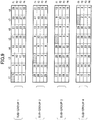
- Fig. 1 illustrates an example of repetition of 3 cells.
- A, B, and C use bandwidths of different center frequencies.
- Fig. 1 illustrates how interference is prevented by prohibiting adjacent cells from using the same frequency. Further, Fig. 1 illustrates that the interference level becomes no greater than a permissible value if the distance between base stations is 3 times the cell radius.
- Fig. 1 also illustrates frequency allocation in a case where cells are assigned the same frequency.
- OFDMA Orthogonal Frequency Division Multiple Access
- a frequency bandwidth is divided into plural sub-channels
- the same sub-channel cannot be simultaneously assigned to adjacent base stations or to sectors of a base station. Accordingly, all cells share the same frequency bandwidth (frequency bandwidth of a center frequency having a given bandwidth) while preventing interference among cells and improving frequency usage efficiency.
- a method of dividing a bandwidth of a system using an OFDMA method into plural clusters is described in, for example, Patent Document 1.
- 3 adjacent cells constitute a single group, as illustrated in Fig. 2 .
- Each of seg1, seg2, and seg3 corresponds to a sub-channel group obtained by dividing a frequency bandwidth having the same center frequency.
- the same sub-channel group is not reused within the same group.
- Three different sub-channel groups are used in each of 3 cells. Further, the same sub-channel is not reassigned within a single group and not among adjacent cells, to thereby perform operations while preventing interference.
- a resource which can be assigned in a next frame is determined in response to a resource assignment request of a given time.
- the resource assignment request does not only correspond to a case where an access request signal is transmitted as an actual signal from a mobile station (MS) but also corresponds to a case where a mobile station is carrying data to be transmitted.
- a state where data to be transmitted are accumulated in a queue for accumulating data may represent a "request".
- a resource assignment plan can be represented with a matrix having a frequency axis (axis in which sub-carriers are arranged) and a time axis. The content of the resource assignment plan is reported to the mobile station.
- Fig. 4 illustrates an example of a format used for mobile communications.
- the "Preamble” is used for synchronization by a mobile station; the "DL MAP” is data indicating a resource assignment plan of a downlink; and the "UL MAP” is data indicating a resource assignment plan of an uplink.
- Each mobile station can perform burst communication using a resource block assigned to the mobile station itself by confirming the DL MAP data or the UL MAP data or both.
- TDD time division duplexing
- uplink (UL) communication is performed after performing downlink (DL) communication.
- the same operation is repeated when a "Preamble" transmitted again from the mobile station is received.
- This method is not a channel assignment method that assigns a resource selected from resources available at the instant of receiving a resource assignment request, but is a method that assigns resources reserved for future use.
- a data modulation method and an encoding code are selected at the same time of assigning channel resources according to a wireless status of a mobile station (MS).
- a modulation method having a high transmission rate such as 64 QAM is assigned.
- a modulation method having a low transmission rate such as QPSK is assigned.
- Patent Document 1 Japanese Laid-Open Publication No. 2004-529524
- Fig. 5 illustrates how a shape of an actual cell is deviated from an ideal hexagonal shape.
- the shape of a cell is ideal, interference waves from other cells using the same frequency are controlled to be below to a value no greater than a permissible value. This state is illustrated in Fig. 6 .
- the interference waves from other cells using the same frequency surpass a permissible value. This state is illustrated in Fig. 7 .
- a sub-channel number equivalent to logical channel division and a sub-carrier number equivalent to physical channel division do not match on a one-to-one basis but are relatively randomized with respect to each cell. Accordingly, the probability of "sub-carrier collision" in which the same sub-channel is simultaneously assigned to different mobile stations among cells using the same frequency bandwidth can be reduced. Interference becomes less as traffic becomes less. Thus, transmission quality can be maintained at a certain degree. In other words, in a case where a small number of sub-channels is sufficient for communications, the probability of sub-carrier collision is statistically low because sub-carrier numbers are randomly selected for each base station where the same frequency bandwidth (sub-carrier group) is used among the cells.
- a determination criterion is the quality of each mobile station (MS) in which the mobile station capable of exhibiting higher throughput is selected.
- Another example of the determination criterion is the opportunity of assignment in which resources are assigned to the mobile stations with a certain degree of evenness so that assignment of resources is not prioritized to a certain mobile station.
- the modulation method assigned to the selected mobile station (MS) is adaptively set, the location of the resource (location on time axis and frequency axis on matrix) to be assigned is randomly selected.
- interference between cells may be large.
- the location of the two mobile stations (MS) to which the same sub-carrier is simultaneously assigned may be a location where interference easily occurs or where interference is applied (typically, cell edge). In such a case, interference of the actual field is very likely to become no less than the permissible value.
- the present invention aims to provide a mobile communications system using FDM (Frequency Division Multiplex) for reducing interference from other cells using the same frequency.
- FDM Frequency Division Multiplex
- interference from other cells using the same frequency can be reduced in a mobile communications system using an FDM (Frequency Division Multiplex) method.
- FDM Frequency Division Multiplex
- shared resource numbers (shared by all cells) are set to corresponding resources (unit resource blocks) designated according to a frequency axis and a time axis of a matrix as illustrated in Fig. 8 .
- t1, t2, ... t8 indicate a unit time in assigning resources.
- the unit time may be set having a given length (for example, an integral multiple of a unit time may constitute a single wireless frame).
- mobile stations having a wireless propagation status good enough to be assigned a resource are selected.
- the selected mobile stations are graded (ranked) based on the quantity indicating the status of wireless propagation status (e.g., SIR, SINR, CQI) and arranged according to their graded quality.
- a MS quality order number (ranking number) is added to each of the mobile stations.
- a series of shared resource numbers are associated with a series of MS quality order numbers based on a predetermined corresponding relationship. This corresponding relationship (correspondence table) is set to each cell according to a certain condition(s).
- the base station Based on SINR information or RSSI information equivalent to quality information reported from the mobile station MS, the base station assigns MS quality order numbers of mobile stations in order, for example, beginning from a target mobile station having a low SINR value or a low RSSI value. For example, in a case where there are 3 target mobile stations, a MS quality order number 1 is assigned to the mobile station having the lowest RSSI value, then a MS quality order number 2 is assigned to the mobile station having the second lowest RSSI value, and then a MS quality order number 3 is assigned to the mobile station having the highest RSSI value.
- Cells in a system are divided into 3 groups (Seg1, Seg2, Seg3) by segmentation.
- the frequency bandwidth used by each cell included in one of the groups (e.g., Seg1) is distinguished by a sub-group number.
- the sub-groups are identified as sub-group 1, sub-group 2, sub-group 3, and sub-group 4.
- the frequency bandwidth (sub-carrier group) used by each of the sub-groups is the same, the corresponding relationship between the shared resource number and the MS quality order number is different for each sub-group.
- the MS quality order number corresponding to a given shared resource number is different if the sub-group is different and is the same if the sub-group is the same.
- a different sub-group number is assigned with respect to near base stations whereas a same sub-group number is assigned with respect to relatively far base stations.
- the mobile station MS having the worst SINR value is assigned to a time axis t1 and a frequency f1.
- the mobile station MS having the worst SINR value is assigned to a time axis t3 and a frequency f1.
- the mobile station MS having the worst SINR value is assigned to a time axis t5 and a frequency f1.
- the mobile station MS having the worst SINR value is assigned to a time axis t7 and a frequency f1.
- the numbers indicated in each unit resource block corresponds to a ranking number.
- a user having a number equivalent to the ranking number is assigned the unit resource block corresponding to the ranking number.
- a cell (BS1) of the sub-group 1 among the users to which resources are assigned, four low ranked (order) users having relatively poor channel status are mapped to a time slot t1.
- a cell (BS2) of the sub-group 2 among the users to which resources are assigned, four low ranked (order) users having relatively poor channel status are mapped to a time slot t3. Therefore, users having poor channel status can be prevented from simultaneously using the same frequency.
- the user having the ninth poor channel status in sub-group 1 and the user having the poorest channel status in sub-group 2 use the same unit resource block t3f1 and may interfere with each other.
- the channel status of the users belonging to sub-group 1 may not necessarily be a worst state, but rather a relatively satisfactory state. Therefore, it is anticipated that the user of sub-group 1 is closer to a base station. Further, the user belonging to sub-group 2 is anticipated to be near a cell end. Accordingly, the interference between the users is less compared to a case where both users are close to a cell end.
- a base station (BS1) assigns a first wireless frequency (f1) to a mobile station belonging to a group having the poorest wireless environment (quality order 1) at the first timing (t1) with priority.
- a base station (BS2) being adjacent to the base station (BS1) and using the same frequency as the base station (BS) also determines a section(s) by using the wireless environment of a corresponding mobile station as a parameter.
- the base station (B2) assigns the first wireless frequency (f1) to a mobile station belonging to a group having the poorest wireless environment (quality order 1) at a second timing (t3) which is different from the first timing (t1) with priority.
- the base station (B2) assigns the first wireless frequency (f1) to a mobile station (e.g., quality order 25) belonging to a group having a better wireless environment than the group having the poorest wireless environment at the first timing (t1) with priority. Accordingly, the risk of the two mobile stations having the worst reception environment (i.e. mobile stations likely to be located on the farthest cell ends) can be prevented from having the same frequency at the same timing.
- a mobile station e.g., quality order 25
- the SINR value or the RSSI value reported from the mobile station to the base station is the ratio between a received power (RSSI value) of a control signal (or pilot signal) constantly transmitted from each cell with fixed transmission power and interference power from other cells or the ratio between received power of a desired signal and interference power from other cells. Therefore, the SINR value or the RSSI value depends on the location of the mobile station (MS) inside the cell. In other words, a mobile station (MS) having a high SINR value (or high RSSI value) is assumed to be a mobile station (MS) located near a center part of a cell.
- a mobile station (MS) having a low SINR value for example, is assumed to be a mobile station (MS) located far from a center part of a cell (a place having low reception power from the corresponding cell and being susceptible to interference from other cells, namely the vicinity of a border of a cell). For the sake of convenience, it is assumed that the combination of the data modulation method assigned to the mobile station and the channel encoding rate is invariable.
- the transmission power from a base station to a mobile station MS located near the center of a cell and the transmission power from a base station to a mobile station MS located at a cell edge are substantially equal. Because propagation loss becomes greater as the mobile station MS becomes farther from the base station, the reception level of the mobile station MS becomes lower as the mobile station MS becomes farther from the base station. On the other hand, the interference level from an interfering base station (base station of another cell using the same sub-channel) becomes larger when the distance from the interfering base station is short whereas the interference level from an interfering base station becomes smaller when the distance from the interference is long.
- the influence of interference does not depend on the location of the mobile station because the transmission power from the base station is constant. From the aspect of the influence of interference received by the mobile station/base station, the reception level of a desired signal becomes higher as the mobile station is closer to the base station. In this case, interference level is low because the mobile station is located far from the interfering base station.
- the order of mobile stations MS starting from the mobile station located farthest from the base station corresponds to the order of mobile stations MS susceptible to interference (the likelihood of receiving interference does not depend on the location of the MS as described above). Therefore, mobile stations which are most susceptible to interference can be prevented from being simultaneously assigned the same sub-channel by setting a corresponding relationship between a shared resource number and a MS quality order number so that unit resource blocks of the same frequency are used at different times in a case where the sub-group is different.
- the transmission power of a base station is controlled so that a mobile station MS receives signals at a desired quality. Because propagation loss is small for a mobile station MS located near the center of a cell, the transmission power from the base station to the mobile station MS does not have to be high. That is, the closer the mobile station is to the base station, the lower the transmission power required by the base station to the mobile station MS may be. Therefore, the influence applied by interference of the base station is small. Further, the closer the mobile station is to the base station, the lower the interference level becomes because the mobile station is located far from other cells which may be the source of interference.
- the transmission power of the base station to the mobile station MS becomes smaller as the mobile station MS is closer to the base station and the reception interference level becomes smaller for the mobile station MS the closer the mobile station is to the base station, the mobile station located near the base station receives less interference and applies less interference. Therefore, the order of mobile stations MS starting from the mobile station located farthest from the base station corresponds to the order of mobile stations MS susceptible to interference and also corresponds to the order of mobiles stations MS more likely to apply interference.
- mobile stations which are most susceptible to interference can be prevented from being simultaneously assigned the same sub-channel by setting a corresponding relationship between a shared resource number and a MS quality order number so that unit resource blocks of the same frequency is used at different times in a case where the sub-group are different.
- the transmission power to a base station from a mobile station MS located near the center of a cell and the transmission power to a base station from a mobile station MS located at a cell edge are substantially equal. Therefore, the reception level of the base station becomes lower as the mobile station MS becomes farther from the base station.
- the interference level of another base station that receives interference differs depending on the distance between the other base station and the mobile station (interfering station). The base station receives greater interference from the mobile station located in a cell edge and receives less interference from the mobile station located near the center of the cell.
- the interference that the mobile station applies to the other base station differs depending on the location of the mobile station.
- the interference applied by the mobile station is small the farther the mobile station is from the other base station.
- the reception level of desired signals becomes higher the farther the mobile station MS is from the base station, and the interference level becomes lower the farther is the mobile station MS. That is, the base station only receives low interference from the mobile station located distant from the base station. Therefore, the order of mobile stations MS starting from the mobile station located farthest from the base station corresponds to the order of mobile stations MS susceptible to interference and also corresponds to the order of mobile stations MS more likely to apply interference.
- mobile stations which are most susceptible to interference can be prevented from being simultaneously assigned the same sub-channel by setting a corresponding relationship between a shared resource number and a MS quality order number so that unit resource blocks of the same frequency are used at different times in a case where the sub-group is different.
- the transmission power of a mobile station is controlled so that a base station can receive an uplink signal of the same quality regardless of the location of the mobile station. Because the reception level of the base station from the mobile station located near the center of a cell exhibits a small propagation loss, the transmission power from the mobile station does not have to be high. That is, the closer the mobile station is to the base station, the lower the transmission power of the mobile station MS is. Therefore, the mobile station MS applies less interference. Further, the closer the mobile station is to the base station, the less interference the mobile station receives from base stations of other cells because the mobile station is located far from other cells. In a case where control of transmission power is performed, the reception level at the base station becomes the same regardless of the location of the mobile station MS. Therefore, the interference received by the base station does not depend on the location of the mobile station MS.
- the transmission power is low the closer the mobile station MS is to the base station and the interference level is low the closer the mobile station MS is to the base station, the mobile station applies less interference to other stations. Accordingly, the interference received by the base station does not depend on the location of the mobile station MS. Therefore, the order of mobile stations MS starting from the mobile station located farthest from the base station corresponds to the order of mobile stations MS susceptible to interference.
- mobile stations which are most susceptible to interference can be prevented from being simultaneously assigned the same sub-channel by setting a corresponding relationship between a shared resource number and a MS quality order number so that unit resource blocks of the same frequency are used at different times in a case where the sub-group is different.
- an embodiment of the present invention determines a corresponding relationship between a shared resource number and a MS quality order number so that such mobile stations do not simultaneously use the same resource.
- a corresponding relationship between shared resource numbers and MS quality order numbers is prepared, and four sub-groups using the same frequency bandwidths f1-f4 are prepared.
- Each of f 1 , f 2 , ... may correspond to a resource assignment unit in the direction of a frequency axis.
- a resource block designated as t1f1 is assigned to a mobile station having the poorest SINR value in a cell (BS1) of sub-group 1.
- This resource block corresponds to a resource block assigned to a mobile station having the 25 th poorest SINR value (in other words, a relatively good quality) in a cell (BS2) of sub-group 2.
- the resource assignment unit t1f1 is a vacant resource in the cell of sub-group 2.
- the corresponding relationship between the numbers is determined in a manner that the mobile station MS having the poorest SINR value in one sub-group (cell) does not simultaneously use the same resource (t1f1 or t3f1) as a mobile station MS having the poorest SINR value in another sub-group.
- the mobile stations having the poorest SINR value are allowed to use the resource block t1f1 only for those belonging to other groups (base stations other than BS1-BS4). Such a base station exists only in a proportion of one out of four cells and is located substantially far away.
- the interference created can be controlled to be substantially less than that of the mobile stations located at the cell border. This is because mobile stations that influence each other are not mobile stations both located near the cell border but are mobile stations in which at least one of the mobile stations is substantially located far from the cell border. If the number of users in a service area is small, it is possible that the resource block unit t1f1 is used by only one mobile station.
- the mobile stations that simultaneously use the resource block unit t1f1 are the mobile station MS1 which is located at the cell border and most susceptible to interference (mobile station MS located in cell 1) and the mobile station MS2 which applies least interference to the mobile station MS1 (mobile station MS located in cell 2).
- the mobile station MS2 is subjected to interference from the MS1 which applies the most interference to other stations, the mobile station MS2 can maintain a desired quality even if the mobile station MS2 receives some interference from the mobile station MS1 because the mobile station MS2 exhibits a relatively good SINR value.
- the corresponding relationship between shared resource numbers and MS quality order numbers is not limited to that illustrated in Fig. 9 .
- Other corresponding relationships for sub-groups belonging to the same group may be used.
- Other corresponding relationships can be used as long as the corresponding relationship of resource assignment is determined beforehand for preventing or minimizing interference and assigning resources so that the mobile stations in a resource table are scattered.
- Fig. 10 illustrates another example of a corresponding relationship between shared resource numbers and MS quality order numbers.
- MS quality order number indicates the order of beginning from the worst SINR value.
- the corresponding relationship is determined in a manner that the total of four MS quality order numbers corresponding to a same shared resource number is the same value with respect to each shared resource number.
- the MS quality order number of the sub-group 1 is "1"
- the MS quality order number of the sub-group 2 is "32”
- the MS quality order number of the sub-group 3 is “9”
- the MS quality order number of the sub-group 4 is "24". Accordingly, the total of the MS quality order numbers is "66”.
- the MS quality order number of the sub-group 1 is "2”
- the MS quality order number of the sub-group 2 is "31”
- the MS quality order number of the sub-group 3 is "10”
- the MS quality order number of the sub-group 4 is "23”. Accordingly, the total of the MS quality order numbers is also "66".
- plural cells using the same frequency bandwidth constitute a single group.
- interference can be substantially reduced. Therefore, in designing cells, the necessity for accurately performing, for example, allocation of cells, slight adjustment of the base station (e.g., adjustment of antenna tilt of each cell, adjustment of power) can be reduced. As a result, parameter adjustment can be performed relatively easily in, for example, a running test performed prior to operations.
- embodiment 1 according to the present invention is described.
- the following description focuses on a method of assignment in an uplink direction.
- the data modulation method and the channel encoding method cannot be adaptively changed, transmission power control is performed.
- the present invention is not limited to these conditions.
- Fig. 11 is a block diagram illustrating functions of a base station according to an embodiment of the present invention.
- Fig. 11 illustrates a wireless transmission/reception part 101, a control part 102, a MS quality measurement result report receiving part 103, a wire connecting part 104, a storage part 105, a group number setting part 106, a sub-group number setting part 107, a resource number/MS quality order number setting part 108, and a MS rearrangement/order number assigning part 109.
- the wireless transmission/reception part 101 is for transmitting/receiving wireless signals via an antenna and performing processes on the wireless signals.
- the processes may include, for example, symbol processing based on an OFDM method, digital/analog conversion, frequency conversion, bandwidth control, power amplification, and analog/digital conversion.
- the control part 102 controls signal processing such as transmission power control or transmission/reception switching.
- the MS quality measurement result report receiving part 103 extracts a measured value from MS quality data included in a signal received from a mobile station.
- the wire connecting part 104 provides an interface function for enabling wire communications with an upper level apparatus such as a wireless network controller (RNC) or an access gateway apparatus (aGW).
- RNC wireless network controller
- aGW access gateway apparatus
- the storage part 105 stores various kinds of information.
- the storage part 105 stores information indicating how the shared resource numbers are set, the corresponding relationship between the shared resource numbers and the MS quality order numbers, and determination criteria for scheduling in resource assignment.
- the group number setting part 106 has a function of determining and identifying, for example, the group number of its cell when activated.
- the sub-group number setting part 107 determines the sub-group which its cell belongs to from groups using the same frequency bandwidth.
- the resource number/MS quality order number setting part 108 determines to which sub-group it belongs to and determines the corresponding relationship (corresponding relationship between shared resource numbers and MS quality order numbers) it should use.
- the MS rearrangement/order number assignment part 109 assigns a MS quality order number to each mobile station based on a quality (e.g., SINR value) reported from each of the mobile stations.
- a quality e.g., SINR value
- the MS quality order number is determined so that the mobile stations are arranged in an order starting from the mobile station having the poorest SINR value.
- the MS quality information included in the information received from the wireless transmission/reception part 101 is extracted and determined by the MS quality measurement result report receiving part 103.
- the determined information is reported to the resource assignment control part (including scheduler function) 102.
- the scheduler performs resource assignment based on the reported information.
- the resource used for the resource assignment is selected from the frequency (sub-channel) of the dividing number used in segmentation of its base station (its cell) set by the group number setting part 107.
- values reported from each mobile station are transmitted from the MS quality measurement result report receiving part 103 to the MS rearrangement/order number assigning part 109.
- the MS rearrangement/order number assigning part 109 arranges the mobile stations MS from the mobile station having the lowest quality data and assigns a corresponding MS quality order number to each mobile station MS.
- the mobile stations that are assigned with the MS quality order numbers are those having a satisfactory channel status enough to be assigned a wireless resource in a subsequent subframe. For example, a number of mobile stations MS having the top MS quality measurement results are assigned with the MS quality order numbers. Accordingly, the number of mobile stations having the top MS quality measurement results are arranged beginning from those having relatively poor quality information and are assigned with corresponding MS quality order numbers.
- the sub-group setting part 107 is for newly setting sub-group numbers within group numbers. Then, the resource number/MS quality order number setting part 108 associates the sub-group numbers with the order numbers assigned to the mobile stations according to a predetermined corresponding relationship. The result of the association is transmitted to the control part 102. Accordingly, the control part performs resource assignment.
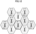
- Fig. 12 illustrates an example of allocation of sub-groups according to an embodiment of the present invention.
- the cells have an omni-configuration.
- sub-channels are repeatedly allocated in 3 zones.
- the system bandwidth is divided into A, B, and C by segmentation.
- Each segment includes 4 sub-groups.
- segment A includes sub-groups A-1, A-2, A-3, and A-4.
- the four sub-groups use the same frequency bandwidth.
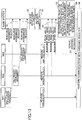
- Fig. 13 is a flowchart illustrating an operation according to an embodiment of the present invention.
- Step S1 each of the mobile stations MS1, MS2, and MS3, sends a request (transmits an assignment request signal) for requesting assignment of a resource.
- Step S2 a group number of the cells is recognized. In the example of Fig. 12 , it is determined which cell the mobile station belongs to.
- Step S3 the sub-group number is confirmed.
- the base station of Fig. 13 corresponds to A-1 of Fig. 12 .
- each of the mobile stations M1, M2, and M3 measures its wireless quality.
- the wireless quality may be, for example, a RSSI value measured by the mobile station. The measured value is reported to the base station.
- Step S5 based on the reported RSSI value, the base station selects a mobile station having a quality satisfactory enough to perform communications in a subsequent wireless frame.
- the mobile stations illustrated of Fig. 3 are all selected.
- the base station arranges the RSSI values beginning from the poorest in order. Based on this order, the base station assigns a MS quality order number to the mobile stations.
- the RSSI value and the location of the mobile station MS (distance from base station (near/far)) have a unique relationship (for example, a relationship which can be linearly approximated). Based on such relationship, the mobile stations MS can be arranged starting from the mobile station farthest from the base station. For example, a MS quality order number of a first number may be assigned starting with the farthest mobile station.
- the mobile stations can be arranged from the one farthest from the base station.
- 3 mobile stations exist in the service area of a center cell (A-1).
- the reception levels of the mobile stations MS1, MS2, and MS3 are -90 dBm, -100 dBm, and -80 dBm, respectively (first and second lines in table of Fig. 14 ).
- the mobile station MS3 having the highest reception level is nearest to the base station.
- the mobile station MS1 having the second highest reception level is located farther from the base station than the mobile station MS3.
- the mobile station having the lowest reception level is located nearest to the cell border among the 3 mobile stations.
- the MS quality order number is arranged starting from the lowest RSSI value.
- MS quality order numbers 1, 2, and 3 are assigned to mobile stations MS2, MS1, and MS3 in this order.
- Three mobile stations also exist in a cell having the same segmentation number but with a different sub-group number (e.g., A-2).
- the reception levels of the mobile stations MS4, MS5, and MS6 are -95 dBm, -85 dBm, and -80 dBm, respectively (third and fourth lines in table of Fig. 14 ).
- the mobile stations are arranged starting from the mobile station farthest from the base station in the order of MS4, MS5, and MS6.
- MS quality order numbers 1, 2, and 3 are assigned to mobile stations MS4, MS5, and MS6 in this order.
- each base station prepares MS quality order numbers for the corresponding mobile station.
- Step S6 of Fig. 13 based on the corresponding relationship determined for the sub-groups, resource assignment is performed by associating MS quality order numbers to corresponding shared resource numbers. Scheduling information indicating the content of the assigned resources is reported to the corresponding mobile station in Step S7. Then, communications are performed in Step S8.
- the corresponding relationship between shared resource numbers and MS quality order numbers in cell 1 is determined as the relationship of sub-group 1 illustrated in Fig. 9
- the corresponding relationship between shared resource numbers and MS quality order numbers in cell 2 is determined as the relationship of sub-group 2 illustrated in Fig. 9
- each mobile station desires to perform communications using four resource block units. Accordingly, in this example, resource assignment is established in the manner illustrated in Fig. 15 .
- a time slot t1 is assigned to a mobile station MS2, a time slot t2 is assigned to a mobile station MS1, and a time slot t3 is assigned to a mobile station MS3.
- a time slot t3 is assigned to a mobile station MS4, a time slot t4 is assigned to a mobile station 5, and a time slot t5 is assigned to a mobile station 6.
- mobile station MS2 and MS4 are located nearest to their respective zone borders and are most susceptible to interference. However, because resources are assigned to the mobile stations MS2 and MS4 in a different time axis, the largest interference, which would be generated if the mobile stations MS2 and MS4 simultaneously use the same resource block, can be prevented.
- the same resource block unit is simultaneously assigned to the mobile station MS3 of cell 1 and the mobile station MS4 of cell 2.
- the mobile stations MS3 and MS4 interfere with each other. Because the mobile station MS4 of cell 2 is located closest to the zone edge, the mobile station MS4 performs transmission power control for using high transmission power and maintains a desired quality. On the other hand, the mobile station MS3 does not perform transmission with full power at least because the mobile station MS3 is located relatively near the center of cell 1. In addition, the mobile station MS3 receives less interference compared to a mobile station located in the zone edge of the cell 1 because the mobile station MS3 is located substantially far from the cell 2. Therefore, it is anticipated that the signal quality of the mobile station MS4 is guaranteed. The mobile station MS4 is assumed to withstand interference from the mobile station MS3 as long as the mobile station MS4 can withstand interference from the zone edge of cell 1.
- the mobile station MS3 because the mobile station MS3 is located near the center of cell 1, its distance from the mobile station MS4 located at the zone edge of cell 2 is greater than that of the mobile stations located near the zone edge of cell 1.
- the reception level of the base station in cell 1 can be maintained at a constant level in a case where transmission power control is performed. Even if there is an increase of interference, quality can be maintained by increasing transmission power to some degree. Therefore, the mobile station MS3 has better quality compared to a case of being assigned with the same resource block unit as the mobile station MS located at the zone edge of the cell 1.
- the upper left cell is assumed as cell 3
- the left cell is assumed as cell 4
- the right cell is assumed as cell 5.
- the cell number and reception level of each mobile station in each cell is illustrated in Fig. 14 .
- the resource assignment table illustrated in Fig. 16 can be obtained by assigning the mobile stations MS1 through MS16 with corresponding MS quality order numbers and corresponding resource locations are associated with the MS quality order numbers for each sub-group number. In this case also, it can be understood that the worst case (case where mobile stations having largest interference simultaneously use the same resource) is positively prevented.
- Mobile stations MS13 and MS16 which have the largest interference in cell 4 and cell 5, simultaneously use the same resource.
- the cells 4 and 5 are not cells using the same frequency A and being located nearest to each other, but have the cell 1 using the same frequency A and being located therebetween.
- the distance between the cells can be increased by appropriately arranging the sub-groups. In other words, neighboring cells are controlled so that mobile stations having highest interference do not simultaneously use the same resource.
- the corresponding relationship between MS quality order numbers and shared resource numbers with respect to each cell may be changed even in a case where the MS quality order numbers are arranged starting from the best RSSI value.
- the numbers are arranged starting from the best RSSI value.
- the users having the best RSSI values and being assigned MS quality order numbers 1, 2, 3, ... are prevented from simultaneously using the same resource block unit.
- users having large MS quality order numbers e.g., users located at the cell edge
- the MS quality order number be arranged in an order starting from a poor quality.
- adaptive modulation and channel encoding may also be applied.
- the data modulation method used in the wireless lines of the mobile station MS may be adaptively changed according to a reception quality status of the mobile station MS. For example, in a case where reception quality is satisfactory, the mobile station MS may be located near the base station. Further, in a case where the SINR value is high, a method exhibiting a large transmission rate (e.g., 64 QAM) may be used. On the other hand, in a case where reception quality is poor, the mobile station MS may be located near the cell border.
- the quality of the mobile station may differ depending on whether the mobile station is located near the center of a cell or near the border of a cell.
- the reception quality of the mobile station decreases to a limit where the high rate modulation method (e.g., 64 QAM) cannot be satisfactory used.
- the modulation method is changed to a low rate modulation method (e.g., 16 QAM) for attaining a desired quality.
- the modulation method is changed to a lower modulation method (e.g., QPSK) for attaining a desired quality.
- a lower modulation method e.g., QPSK
- endurance against interference does not uniformly decrease in correspondence with the distance from the base station.
- the distance from the base station is at the limit distance of the 64 QAM modulation method
- spare power is insufficient for maintaining a satisfactory reception level for the 64 QAM modulation method.
- a low rate method of 16 QAM modulation is used because a satisfactory quality can easily be attained while maintaining spare power.
- the influence of interference does not uniformly decrease in correspondence with the distance from the base station.
- control may become complicated.
Landscapes
- Engineering & Computer Science (AREA)
- Signal Processing (AREA)
- Computer Networks & Wireless Communication (AREA)
- Quality & Reliability (AREA)
- Mobile Radio Communication Systems (AREA)
Description
- The present invention generally relates to the technical field of mobile communications, and more specifically, to a base station and method used in a mobile communications system. The present invention is suitable for, for example, an interference reduction method in a system using a channel resource assignment method in a TDMA/FDMA hybrid system or a WiMAX method in an OFDMA system. Further, the present invention is suitable for, a scheduling method used when assigning units of resource blocks that are designated according to frequency and time to each of the user equipment (UE).
-
US2004190482 A1 refers to a method and apparatus for reducing co-channel interference in a communication system. A downlink frame is divided into similar sized resource blocks with each co-channel sector scheduled to transmit from the beginning of its respective assigned resource block. Transmissions to remote units within the particular sector will occur only within the particular resource block, up to a point where all N resource units have been utilized. Beyond that point, additional transmissions are scheduled to be transmitted at the end of the resource blocks assigned to the other sectors. -
EP0924897 A2 refers to a dynamic resource allocation for broadband services in a wireless communications system. The communications system can have a number of cells, each of which has multiple sectors. Each sector can contain a number of communications sites. Information is transmitted in time subframes scheduled to avoid interference between the sectors and cells, and different degrees of concurrent packet transmission can be scheduled for different classes of communications sites. The communications sites can be classified based on reception quality, such as by comparing their measured signal-to-interference ratio (SIR) with a SIR threshold. - In a mobile communications system using a cellular method, cells are designed so that undetected service areas are not created. As for known cell configurations, there is a method of designing an area with omni-cells using omnidirectional antennas and a method of a 3 sector cell or 6 sector cells constituting a base station area using directional antennas.
- In order to sufficiently allocate the cells and efficiently use limited frequency resources, it is necessary to satisfactorily restrain interference from adjacent and proximal cells. In other words, the frequency allocation method is to be decided so that the interference level from other cells using the same frequency is no greater than a permissible value. With CDMA (Code Division Multiple Access), adjacent cells can use the same frequency because separation with spread codes can be performed. However, with FDMA (Frequency Division Multiple Access), adjacent cells, at least, cannot use the same frequency. Although non-adjacent cells can use the same frequency, the cells using the same frequency are to be separated from each other at a sufficient distance, so that interference between the cells or interference between users can be reduced to a permissible level. By doing so, frequencies can be reused and frequency usage efficiency can be improved. In other words, neighboring cells can exhibit interference no greater than a permissible value by being grouped so that the cells use different frequencies rather than using the same frequency. Accordingly, although the same frequency cannot be used within the same group, the same frequency can be repetitively used by other groups located far from the group. Thereby, a limited number of frequencies can be efficiently used.
- By dividing a frequency band to be assigned to a system operator with the number of cells in a single group, the width of the frequency band per cell can be determined. Accordingly, by reducing the number of divisions, that is, by repetitively reducing the distance, more frequencies can be assigned to each base station. Thus, more traffic can be accommodated and frequencies can be used more efficiently.
-
Fig. 1 illustrates an example of repetition of 3 cells. A, B, and C use bandwidths of different center frequencies.Fig. 1 illustrates how interference is prevented by prohibiting adjacent cells from using the same frequency. Further,Fig. 1 illustrates that the interference level becomes no greater than a permissible value if the distance between base stations is 3 times the cell radius.Fig. 1 also illustrates frequency allocation in a case where cells are assigned the same frequency. - In a system using, for example, WiMAX, OFDMA (Orthogonal Frequency Division Multiple Access) may be used as a multi-channel access method. With this method in which a frequency bandwidth is divided into plural sub-channels, the same sub-channel cannot be simultaneously assigned to adjacent base stations or to sectors of a base station. Accordingly, all cells share the same frequency bandwidth (frequency bandwidth of a center frequency having a given bandwidth) while preventing interference among cells and improving frequency usage efficiency. A method of dividing a bandwidth of a system using an OFDMA method into plural clusters is described in, for example,
Patent Document 1. - For example, there is a method of assigning fixed frequencies by obtaining an allocation beforehand so that interference can be controlled to a value no greater than a permissible value. With WiMAX, the division of sub-channels is referred to as "segmentation". The bandwidth allocated to the system is divided into 3 segments (collection of sub-channels).
- For example, 3 adjacent cells constitute a single group, as illustrated in
Fig. 2 . Each of seg1, seg2, and seg3 corresponds to a sub-channel group obtained by dividing a frequency bandwidth having the same center frequency. The same sub-channel group is not reused within the same group. Three different sub-channel groups are used in each of 3 cells. Further, the same sub-channel is not reassigned within a single group and not among adjacent cells, to thereby perform operations while preventing interference. - With WiMAX, a resource which can be assigned in a next frame is determined in response to a resource assignment request of a given time. The resource assignment request does not only correspond to a case where an access request signal is transmitted as an actual signal from a mobile station (MS) but also corresponds to a case where a mobile station is carrying data to be transmitted. For example, a state where data to be transmitted are accumulated in a queue for accumulating data may represent a "request".
- As illustrated in
Fig. 3 , a resource assignment plan can be represented with a matrix having a frequency axis (axis in which sub-carriers are arranged) and a time axis. The content of the resource assignment plan is reported to the mobile station. -
Fig. 4 illustrates an example of a format used for mobile communications. The "Preamble" is used for synchronization by a mobile station; the "DL MAP" is data indicating a resource assignment plan of a downlink; and the "UL MAP" is data indicating a resource assignment plan of an uplink. Each mobile station can perform burst communication using a resource block assigned to the mobile station itself by confirming the DL MAP data or the UL MAP data or both. In the illustrated example, TDD (time division duplexing) is used, and uplink (UL) communication is performed after performing downlink (DL) communication. Then, although not illustrated, the same operation is repeated when a "Preamble" transmitted again from the mobile station is received. This method is not a channel assignment method that assigns a resource selected from resources available at the instant of receiving a resource assignment request, but is a method that assigns resources reserved for future use. - Further, with WiMAX, a data modulation method and an encoding code are selected at the same time of assigning channel resources according to a wireless status of a mobile station (MS). With respect to a mobile station (MS) that is located in the vicinity of a base station and has a satisfactory reception quality, a modulation method having a high transmission rate such as 64 QAM is assigned. On the other hand, with respect to a mobile station located at a cell boundary (mobile station being located far from a base station and having a poor reception quality), a modulation method having a low transmission rate such as QPSK is assigned. By suitably selecting a combination of a data modulation method and a channel encoding method according to the status of a channel, the throughput of a mobile station can be increased as high as possible according to the environment of the mobile station.
- Patent Document 1: Japanese Laid-Open Publication No.
2004-529524 - With an ideal allocation of hexagonal cells, even in a case where interference among cells using the same sub-channel can be controlled to a value which produces no less a predetermined SIR (Signal to Interference Ratio), the interference may actually become greater than a theoretical value due to factors such as inconsistency of a base station allocation, inconsistency of a cell shape, and inconsistency of an actual radio wave transmission environment. Therefore, it becomes difficult to ensure necessary quality (SIR). As a result, throughput may be degraded and generation of coverage holes may occur.
-
Fig. 5 illustrates how a shape of an actual cell is deviated from an ideal hexagonal shape. In a case where the shape of a cell is ideal, interference waves from other cells using the same frequency are controlled to be below to a value no greater than a permissible value. This state is illustrated inFig. 6 . In a case where the shape of a cell is deviated from an ideal hexagonal shape, the interference waves from other cells using the same frequency surpass a permissible value. This state is illustrated inFig. 7 . - With WiMAX, a sub-channel number equivalent to logical channel division and a sub-carrier number equivalent to physical channel division do not match on a one-to-one basis but are relatively randomized with respect to each cell. Accordingly, the probability of "sub-carrier collision" in which the same sub-channel is simultaneously assigned to different mobile stations among cells using the same frequency bandwidth can be reduced. Interference becomes less as traffic becomes less. Thus, transmission quality can be maintained at a certain degree. In other words, in a case where a small number of sub-channels is sufficient for communications, the probability of sub-carrier collision is statistically low because sub-carrier numbers are randomly selected for each base station where the same frequency bandwidth (sub-carrier group) is used among the cells.
- However, with this method, the probability of collision becomes higher as the usage rate of sub-carriers is increased by growth of traffic. In a case of a full load (a state of congested traffic where each cell needs to use all of a third of a frequency bandwidth divided into thirds), collision and interference always occur. Thus, there is a concern of degrading of quality.
- In a typical resource assigning method, numerous determination criteria are referred to for determining the mobile station (MS) to which a resource is to be assigned in response to requests from mobile stations of each cell requesting resource assignment. One example of a determination criterion is the quality of each mobile station (MS) in which the mobile station capable of exhibiting higher throughput is selected. Another example of the determination criterion is the opportunity of assignment in which resources are assigned to the mobile stations with a certain degree of evenness so that assignment of resources is not prioritized to a certain mobile station. Although the modulation method assigned to the selected mobile station (MS) is adaptively set, the location of the resource (location on time axis and frequency axis on matrix) to be assigned is randomly selected. This is because it is easier to attain a desired quality by assigning an arbitrary resource among the resources assigned to each cell to the mobile station (MS) in view of considering interference reduction by performing sub-channel division. Because the selected mobile station (MS) and the resource location are independently assigned in each cell, the assigning status of other nearby cells is not considered. Thus, in some cases, interference between cells may be large. For example, in a case where the same sub-channel is used by cells (not an adjacent cell but next to the adjacent cell), the location of the two mobile stations (MS) to which the same sub-carrier is simultaneously assigned may be a location where interference easily occurs or where interference is applied (typically, cell edge). In such a case, interference of the actual field is very likely to become no less than the permissible value.
- Increasing the number of groups in which the sub-channel is divided or narrowing the frequency bandwidth used by the groups may be considered for reducing interference of other cells. However, with these methods, transmission delays result due to the narrowing of bandwidths. Thus, there is a concern for loss of throughput.
- Accordingly, there is a desire for a sub-carrier assigning method for reducing the influence of interference where traffic load is large without having to increase the number of divided frequencies Further, in a case where the influence of interference is large, it becomes necessary to strictly perform system quality confirmation (e.g., running test during designing of actual base station or running test prior to operation of the system) and adjustment of the original base station. Therefore, there is a concern of the number of steps for the confirmation and the number of steps for the adjustment becoming too many. It is desired to alleviate such strict constraints in designing frequency allocation and to reduce the number of optimum steps.
- Accordingly, the present invention aims to provide a mobile communications system using FDM (Frequency Division Multiplex) for reducing interference from other cells using the same frequency.
- The invention is defined in the independent claims, to which reference should now be made. Advantageous embodiments are set out in the sub claims.
- According to the present invention, interference from other cells using the same frequency can be reduced in a mobile communications system using an FDM (Frequency Division Multiplex) method.
-
-
FIG. 1 is a diagram illustrating an example of a cell configuration; -
FIG. 2 is a diagram illustrating an example of an arrangement of sub-channels with WIMAX; -
FIG. 3 is a diagram illustrating an example of an arrangement of resources assigned to users A-J; -
FIG. 4 is a diagram illustrating an example of a frame format; -
FIG. 5 is a diagram illustrating how an actual cell shape is deviated from an ideal cell shape; -
FIG. 6 is a diagram illustrating interference of other cells in an ideal cell shape; -
FIG. 7 is a diagram illustrating interference of other cells due to an actual cell shape; -
FIG. 8 is a diagram illustrating an example of shared resource number used in an embodiment of the present invention; -
FIG. 9 is a diagram illustrating an example of a corresponding relationship between a shared resource number and an MS quality order number; -
FIG. 10 is a diagram illustrating another example of a corresponding relationship between a shared resource number and an MS quality order number; -
FIG. 11 is a block diagram illustrating functions of a base station according to an embodiment of the present invention; -
FIG. 12 is a diagram illustrating an example of an assumed arrangement of sub-groups according to an embodiment of the present invention; -
FIG. 13 is a flowchart illustrating an example of an operation according to an embodiment of the present invention; -
FIG. 14 is a diagram illustrating an example of a reception level; -
FIG. 15 is a diagram illustrating how resources are assigned according to a corresponding relationship between a shared resource number and an MS quality order number; -
FIG. 16 is a diagram illustrating how resources are assigned according to a corresponding relationship between a shared resource number and an MS quality order number; and -
FIG. 17 is a schematic diagram illustrating AMC. -
- 101 wireless transmission/reception part
- 102 control part
- 103 MS quality measurement result report receivig part
- 104 wire connecting part
- 105 storage part
- 106 group number setting part
- 107 sub-group number setting part
- 108 resource number/MS quality order number setting part
- 109 MS rearrangement/order number assigning part
- Preferred embodiments of the present invention will be explained with reference to accompanying drawings.
- Next, a principle of an operation of the present invention is described.
- In this embodiment, shared resource numbers (shared by all cells) are set to corresponding resources (unit resource blocks) designated according to a frequency axis and a time axis of a matrix as illustrated in
Fig. 8 . InFig. 8 , t1, t2, ... t8 indicate a unit time in assigning resources. The unit time may be set having a given length (for example, an integral multiple of a unit time may constitute a single wireless frame). - According to an embodiment of the present invention, mobile stations (MS) having a wireless propagation status good enough to be assigned a resource are selected. The selected mobile stations are graded (ranked) based on the quantity indicating the status of wireless propagation status (e.g., SIR, SINR, CQI) and arranged according to their graded quality. A MS quality order number (ranking number) is added to each of the mobile stations. A series of shared resource numbers are associated with a series of MS quality order numbers based on a predetermined corresponding relationship. This corresponding relationship (correspondence table) is set to each cell according to a certain condition(s).
- Based on SINR information or RSSI information equivalent to quality information reported from the mobile station MS, the base station assigns MS quality order numbers of mobile stations in order, for example, beginning from a target mobile station having a low SINR value or a low RSSI value. For example, in a case where there are 3 target mobile stations, a MS
quality order number 1 is assigned to the mobile station having the lowest RSSI value, then a MSquality order number 2 is assigned to the mobile station having the second lowest RSSI value, and then a MSquality order number 3 is assigned to the mobile station having the highest RSSI value. - Cells in a system are divided into 3 groups (Seg1, Seg2, Seg3) by segmentation. The frequency bandwidth used by each cell included in one of the groups (e.g., Seg1) is distinguished by a sub-group number. For example, in a case where a given group includes 4 sub-groups, the sub-groups are identified as
sub-group 1,sub-group 2,sub-group 3, andsub-group 4. Although the frequency bandwidth (sub-carrier group) used by each of the sub-groups is the same, the corresponding relationship between the shared resource number and the MS quality order number is different for each sub-group. The MS quality order number corresponding to a given shared resource number is different if the sub-group is different and is the same if the sub-group is the same. Further, a different sub-group number is assigned with respect to near base stations whereas a same sub-group number is assigned with respect to relatively far base stations. - For example, four kinds of sub-groups using a given frequency bandwidth is provided in a matrix table illustrated in
Fig. 9 . - In
sub-group 1, the mobile station MS having the worst SINR value is assigned to a time axis t1 and a frequency f1. Insub-group 2, the mobile station MS having the worst SINR value is assigned to a time axis t3 and a frequency f1. Insub-group 3, the mobile station MS having the worst SINR value is assigned to a time axis t5 and a frequency f1. Insub-group 4, the mobile station MS having the worst SINR value is assigned to a time axis t7 and a frequency f1. - In
Fig. 9 , the numbers indicated in each unit resource block corresponds to a ranking number. A user having a number equivalent to the ranking number is assigned the unit resource block corresponding to the ranking number. In a cell (BS1) of thesub-group 1, among the users to which resources are assigned, four low ranked (order) users having relatively poor channel status are mapped to a time slot t1. In a cell (BS2) of thesub-group 2, among the users to which resources are assigned, four low ranked (order) users having relatively poor channel status are mapped to a time slot t3. Therefore, users having poor channel status can be prevented from simultaneously using the same frequency. - The user having the ninth poor channel status in
sub-group 1 and the user having the poorest channel status insub-group 2 use the same unit resource block t3f1 and may interfere with each other. However, the channel status of the users belonging tosub-group 1 may not necessarily be a worst state, but rather a relatively satisfactory state. Therefore, it is anticipated that the user ofsub-group 1 is closer to a base station. Further, the user belonging tosub-group 2 is anticipated to be near a cell end. Accordingly, the interference between the users is less compared to a case where both users are close to a cell end. - Accordingly, determination of sections is performed by using the wireless environment of a corresponding mobile station as a parameter. A base station (BS1) assigns a first wireless frequency (f1) to a mobile station belonging to a group having the poorest wireless environment (quality order 1) at the first timing (t1) with priority. A base station (BS2) being adjacent to the base station (BS1) and using the same frequency as the base station (BS) also determines a section(s) by using the wireless environment of a corresponding mobile station as a parameter. The base station (B2) assigns the first wireless frequency (f1) to a mobile station belonging to a group having the poorest wireless environment (quality order 1) at a second timing (t3) which is different from the first timing (t1) with priority. Further, the base station (B2) assigns the first wireless frequency (f1) to a mobile station (e.g., quality order 25) belonging to a group having a better wireless environment than the group having the poorest wireless environment at the first timing (t1) with priority. Accordingly, the risk of the two mobile stations having the worst reception environment (i.e. mobile stations likely to be located on the farthest cell ends) can be prevented from having the same frequency at the same timing.
- Next, an embodiment of the present invention is described in further detail.
- The SINR value or the RSSI value reported from the mobile station to the base station is the ratio between a received power (RSSI value) of a control signal (or pilot signal) constantly transmitted from each cell with fixed transmission power and interference power from other cells or the ratio between received power of a desired signal and interference power from other cells. Therefore, the SINR value or the RSSI value depends on the location of the mobile station (MS) inside the cell. In other words, a mobile station (MS) having a high SINR value (or high RSSI value) is assumed to be a mobile station (MS) located near a center part of a cell. A mobile station (MS) having a low SINR value, for example, is assumed to be a mobile station (MS) located far from a center part of a cell (a place having low reception power from the corresponding cell and being susceptible to interference from other cells, namely the vicinity of a border of a cell). For the sake of convenience, it is assumed that the combination of the data modulation method assigned to the mobile station and the channel encoding rate is invariable.
- In a mobile communications system, there is a case where transmission power is controlled and where transmission power is not controlled. Depending on the case, the manner of operation is different. Accordingly, the case where transmission power is not controlled is described first. Then, the case where transmission power is controlled is described. For the sake of convenience, it is a premise that communications from a mobile station (MS) to a base station (UL: Uplink) and communications from a base station to a mobile station (MS) (DL: Downlink) are performed by a TDD (Time Division Duplexing) method. Because resource assignment for the uplink direction and the downlink direction are performed independently, they are described separately below. It is, however, to be noted that the use of TDD is not a requisite.
- In this case, the transmission power from a base station to a mobile station MS located near the center of a cell and the transmission power from a base station to a mobile station MS located at a cell edge are substantially equal. Because propagation loss becomes greater as the mobile station MS becomes farther from the base station, the reception level of the mobile station MS becomes lower as the mobile station MS becomes farther from the base station. On the other hand, the interference level from an interfering base station (base station of another cell using the same sub-channel) becomes larger when the distance from the interfering base station is short whereas the interference level from an interfering base station becomes smaller when the distance from the interference is long. From the aspect of influence of interference applied to other cells, the influence of interference does not depend on the location of the mobile station because the transmission power from the base station is constant. From the aspect of the influence of interference received by the mobile station/base station, the reception level of a desired signal becomes higher as the mobile station is closer to the base station. In this case, interference level is low because the mobile station is located far from the interfering base station.
- Therefore, the order of mobile stations MS starting from the mobile station located farthest from the base station corresponds to the order of mobile stations MS susceptible to interference (the likelihood of receiving interference does not depend on the location of the MS as described above). Therefore, mobile stations which are most susceptible to interference can be prevented from being simultaneously assigned the same sub-channel by setting a corresponding relationship between a shared resource number and a MS quality order number so that unit resource blocks of the same frequency are used at different times in a case where the sub-group is different.
- In this case, the transmission power of a base station is controlled so that a mobile station MS receives signals at a desired quality. Because propagation loss is small for a mobile station MS located near the center of a cell, the transmission power from the base station to the mobile station MS does not have to be high. That is, the closer the mobile station is to the base station, the lower the transmission power required by the base station to the mobile station MS may be. Therefore, the influence applied by interference of the base station is small. Further, the closer the mobile station is to the base station, the lower the interference level becomes because the mobile station is located far from other cells which may be the source of interference.
- In other words, because the transmission power of the base station to the mobile station MS becomes smaller as the mobile station MS is closer to the base station and the reception interference level becomes smaller for the mobile station MS the closer the mobile station is to the base station, the mobile station located near the base station receives less interference and applies less interference. Therefore, the order of mobile stations MS starting from the mobile station located farthest from the base station corresponds to the order of mobile stations MS susceptible to interference and also corresponds to the order of mobiles stations MS more likely to apply interference.
- Therefore, mobile stations which are most susceptible to interference can be prevented from being simultaneously assigned the same sub-channel by setting a corresponding relationship between a shared resource number and a MS quality order number so that unit resource blocks of the same frequency is used at different times in a case where the sub-group are different.
- In this case, the transmission power to a base station from a mobile station MS located near the center of a cell and the transmission power to a base station from a mobile station MS located at a cell edge are substantially equal. Therefore, the reception level of the base station becomes lower as the mobile station MS becomes farther from the base station. On the other hand, the interference level of another base station that receives interference differs depending on the distance between the other base station and the mobile station (interfering station). The base station receives greater interference from the mobile station located in a cell edge and receives less interference from the mobile station located near the center of the cell.
- In other words, the interference that the mobile station applies to the other base station differs depending on the location of the mobile station. The interference applied by the mobile station is small the farther the mobile station is from the other base station. In the base station receiving interference, the reception level of desired signals becomes higher the farther the mobile station MS is from the base station, and the interference level becomes lower the farther is the mobile station MS. That is, the base station only receives low interference from the mobile station located distant from the base station. Therefore, the order of mobile stations MS starting from the mobile station located farthest from the base station corresponds to the order of mobile stations MS susceptible to interference and also corresponds to the order of mobile stations MS more likely to apply interference.
- Therefore, mobile stations which are most susceptible to interference can be prevented from being simultaneously assigned the same sub-channel by setting a corresponding relationship between a shared resource number and a MS quality order number so that unit resource blocks of the same frequency are used at different times in a case where the sub-group is different.
- In this case, the transmission power of a mobile station is controlled so that a base station can receive an uplink signal of the same quality regardless of the location of the mobile station. Because the reception level of the base station from the mobile station located near the center of a cell exhibits a small propagation loss, the transmission power from the mobile station does not have to be high. That is, the closer the mobile station is to the base station, the lower the transmission power of the mobile station MS is. Therefore, the mobile station MS applies less interference. Further, the closer the mobile station is to the base station, the less interference the mobile station receives from base stations of other cells because the mobile station is located far from other cells. In a case where control of transmission power is performed, the reception level at the base station becomes the same regardless of the location of the mobile station MS. Therefore, the interference received by the base station does not depend on the location of the mobile station MS.
- In other words, because the transmission power is low the closer the mobile station MS is to the base station and the interference level is low the closer the mobile station MS is to the base station, the mobile station applies less interference to other stations. Accordingly, the interference received by the base station does not depend on the location of the mobile station MS. Therefore, the order of mobile stations MS starting from the mobile station located farthest from the base station corresponds to the order of mobile stations MS susceptible to interference.
- Therefore, mobile stations which are most susceptible to interference can be prevented from being simultaneously assigned the same sub-channel by setting a corresponding relationship between a shared resource number and a MS quality order number so that unit resource blocks of the same frequency are used at different times in a case where the sub-group is different.
- In view of the above, a case where mutual interference (applying interference/receiving interference) is large corresponds to a case where mobile stations located near a cell border simultaneously use the same frequency. Accordingly, interference of other cells can be prevented if resources are assigned to avoid such cases from occurring.
- Because mobile stations MS having a low SINR value or a low RSSI value are likely to be located at a cell border, an embodiment of the present invention determines a corresponding relationship between a shared resource number and a MS quality order number so that such mobile stations do not simultaneously use the same resource.
- For example, as illustrated in
Fig. 9 , a corresponding relationship between shared resource numbers and MS quality order numbers is prepared, and four sub-groups using the same frequency bandwidths f1-f4 are prepared. Each of f1, f2, ... may correspond to a resource assignment unit in the direction of a frequency axis. In the example illustrated inFig. 9 , a resource block designated as t1f1 is assigned to a mobile station having the poorest SINR value in a cell (BS1) ofsub-group 1. This resource block corresponds to a resource block assigned to a mobile station having the 25th poorest SINR value (in other words, a relatively good quality) in a cell (BS2) ofsub-group 2. In a case where the number of users located in cell (BS2) ofsub-group 2 is less than 25, the resource assignment unit t1f1 is a vacant resource in the cell ofsub-group 2. The corresponding relationship between the numbers is determined in a manner that the mobile station MS having the poorest SINR value in one sub-group (cell) does not simultaneously use the same resource (t1f1 or t3f1) as a mobile station MS having the poorest SINR value in another sub-group. The mobile stations having the poorest SINR value are allowed to use the resource block t1f1 only for those belonging to other groups (base stations other than BS1-BS4). Such a base station exists only in a proportion of one out of four cells and is located substantially far away. Because assigning resource block unit t1f1 to the mobile station having the poorest SINR is restricted, even if there are plural mobile stations using the resource block unit t1f1 in the remaining 3 cells in the same group (e.g., Seg1), the interference created can be controlled to be substantially less than that of the mobile stations located at the cell border. This is because mobile stations that influence each other are not mobile stations both located near the cell border but are mobile stations in which at least one of the mobile stations is substantially located far from the cell border. If the number of users in a service area is small, it is possible that the resource block unit t1f1 is used by only one mobile station. - In other words, the mobile stations that simultaneously use the resource block unit t1f1 are the mobile station MS1 which is located at the cell border and most susceptible to interference (mobile station MS located in cell 1) and the mobile station MS2 which applies least interference to the mobile station MS1 (mobile station MS located in cell 2). On the other hand, although the mobile station MS2 is subjected to interference from the MS1 which applies the most interference to other stations, the mobile station MS2 can maintain a desired quality even if the mobile station MS2 receives some interference from the mobile station MS1 because the mobile station MS2 exhibits a relatively good SINR value.
- Conventionally, there is a possibility that the same resource block unit be assigned to mobile stations located nearest to each other because the resource block units are independently randomly selected in each sub-group using the same frequency bandwidth. Thus, there is a concern that, in some cases, disconnection or inability to receive data may occur. Such concern can be resolved with this method according to an embodiment of the present invention.
- The corresponding relationship between shared resource numbers and MS quality order numbers is not limited to that illustrated in
Fig. 9 . Other corresponding relationships for sub-groups belonging to the same group may be used. Other corresponding relationships can be used as long as the corresponding relationship of resource assignment is determined beforehand for preventing or minimizing interference and assigning resources so that the mobile stations in a resource table are scattered. -
Fig. 10 illustrates another example of a corresponding relationship between shared resource numbers and MS quality order numbers. In the example ofFig. 10 , MS quality order number indicates the order of beginning from the worst SINR value. In four sub-groups (cells) belonging to the same group (Seg1), the corresponding relationship is determined in a manner that the total of four MS quality order numbers corresponding to a same shared resource number is the same value with respect to each shared resource number. - For example, with respect to the resource block unit t1f1, the MS quality order number of the
sub-group 1 is "1", the MS quality order number of thesub-group 2 is "32", the MS quality order number of thesub-group 3 is "9", and the MS quality order number of thesub-group 4 is "24". Accordingly, the total of the MS quality order numbers is "66". Likewise, with respect to the resource block unit t1f2, the MS quality order number of thesub-group 1 is "2", the MS quality order number of thesub-group 2 is "31", the MS quality order number of thesub-group 3 is "10", and the MS quality order number of thesub-group 4 is "23". Accordingly, the total of the MS quality order numbers is also "66". By making the total value of the MS quality order numbers constant, it is anticipated that the interference in each resource block unit will be substantially the same. - As described above, plural cells using the same frequency bandwidth constitute a single group. By dividing the group into plural sub-groups and assigning different resources to each sub-group, interference can be substantially reduced. Therefore, in designing cells, the necessity for accurately performing, for example, allocation of cells, slight adjustment of the base station (e.g., adjustment of antenna tilt of each cell, adjustment of power) can be reduced. As a result, parameter adjustment can be performed relatively easily in, for example, a running test performed prior to operations.
- Next,
embodiment 1 according to the present invention is described. For the sake of convenience, the following description focuses on a method of assignment in an uplink direction.
Further, although the data modulation method and the channel encoding method cannot be adaptively changed, transmission power control is performed. However, the present invention is not limited to these conditions. -
Fig. 11 is a block diagram illustrating functions of a base station according to an embodiment of the present invention.Fig. 11 illustrates a wireless transmission/reception part 101, acontrol part 102, a MS quality measurement resultreport receiving part 103, awire connecting part 104, astorage part 105, a groupnumber setting part 106, a sub-groupnumber setting part 107, a resource number/MS quality ordernumber setting part 108, and a MS rearrangement/ordernumber assigning part 109. - The wireless transmission/
reception part 101 is for transmitting/receiving wireless signals via an antenna and performing processes on the wireless signals. The processes may include, for example, symbol processing based on an OFDM method, digital/analog conversion, frequency conversion, bandwidth control, power amplification, and analog/digital conversion. - The
control part 102 controls signal processing such as transmission power control or transmission/reception switching. - The MS quality measurement result
report receiving part 103 extracts a measured value from MS quality data included in a signal received from a mobile station. - The
wire connecting part 104 provides an interface function for enabling wire communications with an upper level apparatus such as a wireless network controller (RNC) or an access gateway apparatus (aGW). - The
storage part 105 stores various kinds of information. In this embodiment, thestorage part 105 stores information indicating how the shared resource numbers are set, the corresponding relationship between the shared resource numbers and the MS quality order numbers, and determination criteria for scheduling in resource assignment. - The group
number setting part 106 has a function of determining and identifying, for example, the group number of its cell when activated. - The sub-group
number setting part 107 determines the sub-group which its cell belongs to from groups using the same frequency bandwidth. - The resource number/MS quality order
number setting part 108 determines to which sub-group it belongs to and determines the corresponding relationship (corresponding relationship between shared resource numbers and MS quality order numbers) it should use. - The MS rearrangement/order
number assignment part 109 assigns a MS quality order number to each mobile station based on a quality (e.g., SINR value) reported from each of the mobile stations. Typically, the MS quality order number is determined so that the mobile stations are arranged in an order starting from the mobile station having the poorest SINR value. - In general, the MS quality information included in the information received from the wireless transmission/
reception part 101 is extracted and determined by the MS quality measurement resultreport receiving part 103. The determined information is reported to the resource assignment control part (including scheduler function) 102. The scheduler performs resource assignment based on the reported information. The resource used for the resource assignment is selected from the frequency (sub-channel) of the dividing number used in segmentation of its base station (its cell) set by the groupnumber setting part 107. - In this embodiment, values reported from each mobile station are transmitted from the MS quality measurement result
report receiving part 103 to the MS rearrangement/ordernumber assigning part 109. The MS rearrangement/ordernumber assigning part 109 arranges the mobile stations MS from the mobile station having the lowest quality data and assigns a corresponding MS quality order number to each mobile station MS. The mobile stations that are assigned with the MS quality order numbers are those having a satisfactory channel status enough to be assigned a wireless resource in a subsequent subframe. For example, a number of mobile stations MS having the top MS quality measurement results are assigned with the MS quality order numbers. Accordingly, the number of mobile stations having the top MS quality measurement results are arranged beginning from those having relatively poor quality information and are assigned with corresponding MS quality order numbers. - The
sub-group setting part 107 is for newly setting sub-group numbers within group numbers. Then, the resource number/MS quality ordernumber setting part 108 associates the sub-group numbers with the order numbers assigned to the mobile stations according to a predetermined corresponding relationship. The result of the association is transmitted to thecontrol part 102. Accordingly, the control part performs resource assignment. -
Fig. 12 illustrates an example of allocation of sub-groups according to an embodiment of the present invention. The cells have an omni-configuration. In the cells, sub-channels are repeatedly allocated in 3 zones. The system bandwidth is divided into A, B, and C by segmentation. Each segment (each group) includes 4 sub-groups. For example, segment A includes sub-groups A-1, A-2, A-3, and A-4. The four sub-groups use the same frequency bandwidth. -
Fig. 13 is a flowchart illustrating an operation according to an embodiment of the present invention. In Step S1, each of the mobile stations MS1, MS2, and MS3, sends a request (transmits an assignment request signal) for requesting assignment of a resource. - In Step S2, a group number of the cells is recognized. In the example of
Fig. 12 , it is determined which cell the mobile station belongs to. - In Step S3, the sub-group number is confirmed. For example, the base station of
Fig. 13 corresponds to A-1 ofFig. 12 . - In Step S4, each of the mobile stations M1, M2, and M3 measures its wireless quality. The wireless quality may be, for example, a RSSI value measured by the mobile station. The measured value is reported to the base station.
- In Step S5, based on the reported RSSI value, the base station selects a mobile station having a quality satisfactory enough to perform communications in a subsequent wireless frame. For the sake of convenience, the mobile stations illustrated of
Fig. 3 are all selected. The base station arranges the RSSI values beginning from the poorest in order. Based on this order, the base station assigns a MS quality order number to the mobile stations. Typically, the RSSI value and the location of the mobile station MS (distance from base station (near/far)) have a unique relationship (for example, a relationship which can be linearly approximated). Based on such relationship, the mobile stations MS can be arranged starting from the mobile station farthest from the base station. For example, a MS quality order number of a first number may be assigned starting with the farthest mobile station. By obtaining the location information of the mobile station, the mobile stations can be arranged from the one farthest from the base station. - In the example of
Fig. 12 ,3 mobile stations (MS1, MS2, MS3) exist in the service area of a center cell (A-1). In this example, the reception levels of the mobile stations MS1, MS2, and MS3 are -90 dBm, -100 dBm, and -80 dBm, respectively (first and second lines in table ofFig. 14 ). In this case, the mobile station MS3 having the highest reception level is nearest to the base station. The mobile station MS1 having the second highest reception level is located farther from the base station than the mobile station MS3. The mobile station having the lowest reception level is located nearest to the cell border among the 3 mobile stations. The MS quality order number is arranged starting from the lowest RSSI value. Thus, MSquality order numbers - Three mobile stations (MS4, MS5, MS6) also exist in a cell having the same segmentation number but with a different sub-group number (e.g., A-2). Also in this example, the reception levels of the mobile stations MS4, MS5, and MS6 are -95 dBm, -85 dBm, and -80 dBm, respectively (third and fourth lines in table of
Fig. 14 ). In this case also, the mobile stations are arranged starting from the mobile station farthest from the base station in the order of MS4, MS5, and MS6. Thus, MSquality order numbers - In this manner, each base station prepares MS quality order numbers for the corresponding mobile station.
- In Step S6 of
Fig. 13 , based on the corresponding relationship determined for the sub-groups, resource assignment is performed by associating MS quality order numbers to corresponding shared resource numbers. Scheduling information indicating the content of the assigned resources is reported to the corresponding mobile station in Step S7. Then, communications are performed in Step S8. - In one example, the corresponding relationship between shared resource numbers and MS quality order numbers in
cell 1 is determined as the relationship ofsub-group 1 illustrated inFig. 9 , and the corresponding relationship between shared resource numbers and MS quality order numbers incell 2 is determined as the relationship ofsub-group 2 illustrated inFig. 9 . Further, in this example, each mobile station desires to perform communications using four resource block units. Accordingly, in this example, resource assignment is established in the manner illustrated inFig. 15 . - As illustrated in
Fig. 15 , incell 1, a time slot t1 is assigned to a mobile station MS2, a time slot t2 is assigned to a mobile station MS1, and a time slot t3 is assigned to a mobile station MS3. Meanwhile, incell 2, a time slot t3 is assigned to a mobile station MS4, a time slot t4 is assigned to amobile station 5, and a time slot t5 is assigned to amobile station 6. In the corresponding cells, mobile station MS2 and MS4 are located nearest to their respective zone borders and are most susceptible to interference. However, because resources are assigned to the mobile stations MS2 and MS4 in a different time axis, the largest interference, which would be generated if the mobile stations MS2 and MS4 simultaneously use the same resource block, can be prevented. - In this example, the same resource block unit is simultaneously assigned to the mobile station MS3 of
cell 1 and the mobile station MS4 ofcell 2. Thus, the mobile stations MS3 and MS4 interfere with each other. Because the mobile station MS4 ofcell 2 is located closest to the zone edge, the mobile station MS4 performs transmission power control for using high transmission power and maintains a desired quality. On the other hand, the mobile station MS3 does not perform transmission with full power at least because the mobile station MS3 is located relatively near the center ofcell 1. In addition, the mobile station MS3 receives less interference compared to a mobile station located in the zone edge of thecell 1 because the mobile station MS3 is located substantially far from thecell 2. Therefore, it is anticipated that the signal quality of the mobile station MS4 is guaranteed. The mobile station MS4 is assumed to withstand interference from the mobile station MS3 as long as the mobile station MS4 can withstand interference from the zone edge ofcell 1. - Meanwhile, because the mobile station MS3 is located near the center of
cell 1, its distance from the mobile station MS4 located at the zone edge ofcell 2 is greater than that of the mobile stations located near the zone edge ofcell 1. The reception level of the base station incell 1 can be maintained at a constant level in a case where transmission power control is performed. Even if there is an increase of interference, quality can be maintained by increasing transmission power to some degree. Therefore, the mobile station MS3 has better quality compared to a case of being assigned with the same resource block unit as the mobile station MS located at the zone edge of thecell 1. - As illustrated in
Fig. 12 , with respect to acell 1 serving as the center cell, the upper left cell is assumed ascell 3, the left cell is assumed ascell 4, and the right cell is assumed ascell 5. The cell number and reception level of each mobile station in each cell is illustrated inFig. 14 . - The resource assignment table illustrated in
Fig. 16 can be obtained by assigning the mobile stations MS1 through MS16 with corresponding MS quality order numbers and corresponding resource locations are associated with the MS quality order numbers for each sub-group number. In this case also, it can be understood that the worst case (case where mobile stations having largest interference simultaneously use the same resource) is positively prevented. - Mobile stations MS13 and MS16, which have the largest interference in
cell 4 andcell 5, simultaneously use the same resource. However, thecells cell 1 using the same frequency A and being located therebetween. Although four sub-groups are repeated, the distance between the cells can be increased by appropriately arranging the sub-groups. In other words, neighboring cells are controlled so that mobile stations having highest interference do not simultaneously use the same resource. - It is to be noted that the corresponding relationship between MS quality order numbers and shared resource numbers with respect to each cell may be changed even in a case where the MS quality order numbers are arranged starting from the best RSSI value. In the following example, it is supposed that the numbers are arranged starting from the best RSSI value. In this case, the users having the best RSSI values and being assigned MS
quality order numbers sub-groups - According to an embodiment of the present invention, adaptive modulation and channel encoding (AMC) may also be applied. For the sake of convenience, no transmission power control is performed. With the adaptive modulation method, the data modulation method used in the wireless lines of the mobile station MS may be adaptively changed according to a reception quality status of the mobile station MS. For example, in a case where reception quality is satisfactory, the mobile station MS may be located near the base station. Further, in a case where the SINR value is high, a method exhibiting a large transmission rate (e.g., 64 QAM) may be used. On the other hand, in a case where reception quality is poor, the mobile station MS may be located near the cell border. Further, in a case where the SINR value is low, a method exhibiting a low transmission rate (e.g., QPSK method) may be used. Accordingly, in a case where different modulation methods are used, the quality of the mobile station may differ depending on whether the mobile station is located near the center of a cell or near the border of a cell.
- As illustrated in
Fig. 17 , as the location of the mobile station capable of using a high rate modulation method (e.g., 64 QAM) gradually moves away from the center of the cell, the reception quality of the mobile station decreases to a limit where the high rate modulation method (e.g., 64 QAM) cannot be satisfactory used. Further, when the mobile station modes to a location far from the base station, the modulation method is changed to a low rate modulation method (e.g., 16 QAM) for attaining a desired quality. As the mobile station using the low rate modulation method moves farther from the base station to a limit where the low rate modulation method (e.g., 16 QAM) can no longer maintain a satisfactory quality, the modulation method is changed to a lower modulation method (e.g., QPSK) for attaining a desired quality. - In a case where the AMC method is used, endurance against interference does not uniformly decrease in correspondence with the distance from the base station. For example, in a case where the distance from the base station is at the limit distance of the 64 QAM modulation method, spare power (endurance) is insufficient for maintaining a satisfactory reception level for the 64 QAM modulation method. However, in a case of a location farther than the limit distance, a low rate method of 16 QAM modulation is used because a satisfactory quality can easily be attained while maintaining spare power.
- Therefore, unlike the fixed modulation method (or unlike the above-described relationship between distance and interference using the same modulation method), the influence of interference (applying interference/receiving interference) does not uniformly decrease in correspondence with the distance from the base station. In this case, although it is possible to rearrange the order of the MS quality order number, control may become complicated.
- However, such complication can be resolved by, for example, determining the endurance (spare power) in a case of the modulation method having the lowest transmission rate (i.e. the modulation method having the lowest reception level). By doing so, even if a desired quality cannot be attained by a modulation method adaptively used, desired communication can be continued by using a modulation method having its rate lowered one level. Therefore, the method described in the first embodiment may also be applied.
- All examples and conditional language recited herein are intended for pedagogical purposes to aid the reader in understanding the invention and the concepts contributed by the inventor to furthering the art, and are to be construed as being without limitation to such specifically recited examples and conditions, nor does the organization of such examples in the specification relate to a showing of the superiority and inferiority of the invention. Although the embodiments of the present invention have been described in detail, it should be understood that the various changes, substitutions, and alterations could be made hereto without departing from the scope of the invention.
Claims (10)
- A base station belonging to one of plural cells using a same portion of a system bandwidth, comprising :a part (103) configured to determine which user apparatus among the user apparatuses existing in a service area should be assigned one or more resource block units of a matrix having a time axis and a frequency axis, the resource block unit having a predetermined bandwidth in the matrix and a predetermined time period in the matrix and being identified by a shared resource number shared by the plural cells;a part (109) configured to grade the plural user apparatuses based on a wireless propagation quality status of each of the plural user apparatuses and determine ranking numbers corresponding to the plural user apparatuses;a part (108, 102) configured to generate assignment information indicating which of the plural user apparatus should be assigned to which of the resource block units according to a predetermined corresponding relationship between the shared resource number and the ranking number, wherein the ranking numbers represent the order of the relative quality of the wireless propagation quality status of each of the plural user apparatuses relative to each other, and wherein the ranking numbers are associated to corresponding shared resource numbers, the assignment information allowing user apparatuses from among the plural user apparatuses having relatively poor wireless propagation quality to be prevented from simultaneously using the same frequency; anda part (101) configured to report the assignment information to the corresponding plural user apparatuses;wherein the predetermined corresponding relationship is determined to be different among the plural cells using the same frequency bandwidth.
- The base station as claimed in claim 1, characterized in that the predetermined corresponding relationship is determined so that resource block units having the same frequency but with different time spans are assigned to the user apparatuses having the same ranking number.
- The base station as claimed in claim 1, characterized in that an arrangement of ranking numbers represents the distance from a user apparatus.
- The base station as claimed in claim 1, characterized in that the predetermined corresponding relationship is determined so that, among the plural cells using the same frequency bandwidth, a difference between one ranking number of one cell corresponding to one shared resource number and another ranking number of another cell is equal to a difference between the ranking number of the other cell corresponding to the other shared resource number and the ranking number of the other cell.
- The base station as claimed in claim 1, characterized in that one of the two cells using the same frequency bandwidth has the ranking order of an ascending order associated with a series of shared resource numbers, wherein the other has the ranking order of a descending order associated with a series of shared resource numbers.
- The base station as claimed in claim 1, characterized in that the predetermined corresponding relationship is determined so that, among the plural cells using the same frequency bandwidth, the total value of plural ranking numbers corresponding to one shared resource number is equal to the total value of plural ranking numbers corresponding to another shared resource number.
- The base station as claimed in claim 1, characterized in that the base station is configured to use a mobile communications system of an OFDMA (Orthogonal Frequency Division Multiple Access).
- The base station as claimed in claim 1, characterized in that, in a case where an adaptive modulation and channel encoding (AMC) method is used, the wireless propagation quality status is represented as a reserved power that is anticipated when a predetermined combination of a data modulation method and a channel encoding rate is used for attaining a desired quality.
- A method used for a base station belonging to one of plural cells using a same portion of a system bandwidth, comprising:determining which user apparatus among the user apparatuses existing in a service area should be assigned one or more resource block units of a matrix having a time axis and a frequency axis, the resource block unit having a predetermined bandwidth in the matrix and a predetermined time period in the matrix and being identified by a shared resource number shared by the plural cells;grading the plural user apparatuses based on a wireless propagation quality status of each of the plural user apparatuses and determining ranking numbers corresponding to the plural user apparatuses;generating assignment information indicating which of the plural user apparatuses should be assigned to which of the resource block units according to a predetermined corresponding relationship between the shared resource number and the ranking number, wherein the ranking numbers represent the order of the relative quality of the wireless propagation quality status of each of the plural user apparatuses relative to each other, and wherein the ranking numbers are associated to corresponding shared resource numbers the assignment information allowing user apparatuses from among the plural user apparatuses having relatively poor wireless propagation quality to be prevented from simultaneously using the same frequency;; andreporting the assignment information to the corresponding plural user apparatuses;wherein the predetermined corresponding relationship is determined to be different among the plural cells using the same frequency bandwidth.
- A wireless communication system comprising a base station according to any of claims 1 to 8.
Applications Claiming Priority (1)
| Application Number | Priority Date | Filing Date | Title |
|---|---|---|---|
| PCT/JP2007/055264 WO2008111224A1 (en) | 2007-03-15 | 2007-03-15 | Base station and method used in mobile communication system |
Publications (3)
| Publication Number | Publication Date |
|---|---|
| EP2139249A1 EP2139249A1 (en) | 2009-12-30 |
| EP2139249A4 EP2139249A4 (en) | 2012-11-21 |
| EP2139249B1 true EP2139249B1 (en) | 2017-09-20 |
Family
ID=39759172
Family Applications (1)
| Application Number | Title | Priority Date | Filing Date |
|---|---|---|---|
| EP07738714.0A Not-in-force EP2139249B1 (en) | 2007-03-15 | 2007-03-15 | Base station and method used in mobile communication system |
Country Status (4)
| Country | Link |
|---|---|
| US (1) | US8630243B2 (en) |
| EP (1) | EP2139249B1 (en) |
| JP (1) | JP4935896B2 (en) |
| WO (1) | WO2008111224A1 (en) |
Families Citing this family (22)
| Publication number | Priority date | Publication date | Assignee | Title |
|---|---|---|---|---|
| US8929281B2 (en) | 2006-09-15 | 2015-01-06 | Qualcomm Incorporated | Methods and apparatus related to peer to peer device |
| US8369800B2 (en) * | 2006-09-15 | 2013-02-05 | Qualcomm Incorporated | Methods and apparatus related to power control and/or interference management in a mixed wireless communications system |
| KR100936696B1 (en) * | 2007-11-16 | 2010-01-13 | 고려대학교 산학협력단 | Bandwidth Distributed Resource Allocation Method and Device in Orthogonal Frequency Division Multiple Access System |
| WO2009072184A1 (en) | 2007-12-04 | 2009-06-11 | Fujitsu Limited | Scheduling metho, radio base station and radio terminal |
| WO2009148166A1 (en) * | 2008-06-06 | 2009-12-10 | 株式会社エヌ・ティ・ティ・ドコモ | Mobile communication method and network apparatus |
| WO2010044487A1 (en) * | 2008-10-16 | 2010-04-22 | 日本電気株式会社 | Resource allocation method in reservation scheduling and resource allocation system |
| CN102217141A (en) * | 2008-11-14 | 2011-10-12 | 夏普株式会社 | Antenna device and base station device |
| US8190083B2 (en) * | 2008-11-18 | 2012-05-29 | Qualcomm Incorporated | Methods and apparatus for communicating in a system including relay stations |
| JP5047151B2 (en) * | 2008-12-26 | 2012-10-10 | 株式会社コンテック | Wireless LAN system |
| CA2772443A1 (en) * | 2009-09-02 | 2011-03-10 | Rockstar Bidco, LP | Transmission of multicast broadcast service (mbs) traffic in a wireless environment |
| JP4901947B2 (en) * | 2009-12-16 | 2012-03-21 | 株式会社エヌ・ティ・ティ・ドコモ | Control apparatus and mobile communication method |
| US8724610B2 (en) * | 2010-01-28 | 2014-05-13 | Alcatel Lucent | Interference reduction for wireless networks |
| CA2789439C (en) * | 2010-02-12 | 2017-01-03 | Research In Motion Limited | Reference signal for a coordinated multi-point network implementation |
| WO2011125929A1 (en) * | 2010-04-02 | 2011-10-13 | 日本電気株式会社 | Setting apparatus, communication system, base station and program |
| JP5284316B2 (en) * | 2010-08-12 | 2013-09-11 | 日本電信電話株式会社 | Wireless communication system and wireless communication method |
| CN103139125B (en) * | 2011-12-02 | 2016-04-13 | 华为技术有限公司 | Downlink data sending, receiving method and base station and user terminal |
| GB2505965B (en) * | 2012-09-18 | 2015-06-10 | Toshiba Res Europ Ltd | Controller for coordinating wireless transmissions between a plurality of radio units and one or more user devices |
| JP2014187596A (en) * | 2013-03-25 | 2014-10-02 | Nec Corp | Base station device and control method therefor |
| US20160165630A1 (en) * | 2013-07-11 | 2016-06-09 | Interdigital Patent Holdings, Inc. | Methods and procedures for scheduling to sector-edge and non-sector-edge station groups |
| CN104507092B (en) * | 2014-12-04 | 2017-11-17 | 中国联合网络通信集团有限公司 | A kind of disturbance restraining method and system based on heterogeneous network |
| CN106922013B (en) * | 2015-12-24 | 2020-04-21 | 华为技术有限公司 | Wireless access point with dual radio frequency modules in the same frequency band and method for reducing signal interference |
| JP6967359B2 (en) * | 2017-03-03 | 2021-11-17 | 株式会社Nttドコモ | Wireless base station and scheduling method |
Family Cites Families (12)
| Publication number | Priority date | Publication date | Assignee | Title |
|---|---|---|---|---|
| JP2972476B2 (en) | 1993-02-17 | 1999-11-08 | 日本電気通信システム株式会社 | Base station selection method and base station selection method for cellular wireless telephone system |
| US6011786A (en) * | 1997-06-06 | 2000-01-04 | Ericsson Inc. | Systems and methods for control channel communication in cellular radiotelephone systems |
| US6157627A (en) * | 1997-06-23 | 2000-12-05 | Telefonaktiebolaget Lm Ericsson | Channel allocation for mixed multislot services |
| US6262980B1 (en) * | 1997-12-02 | 2001-07-17 | At&T Corp | Dynamic resource allocation method and apparatus for broadband services in a wireless communications system |
| AU2002235217A1 (en) | 2000-12-15 | 2002-06-24 | Broadstorm Telecommunications, Inc. | Multi-carrier communications with adaptive cluster configuration and switching |
| US7016319B2 (en) * | 2003-03-24 | 2006-03-21 | Motorola, Inc. | Method and apparatus for reducing co-channel interference in a communication system |
| KR20050028354A (en) * | 2003-09-17 | 2005-03-23 | 삼성전자주식회사 | System and method for dynamic channel allocation in communication system using orthogonal frequency division multiple access scheme |
| ATE366020T1 (en) * | 2005-08-01 | 2007-07-15 | Alcatel Lucent | REDUCING THE OVERHEAD FOR CHANNEL ALLOCATION IN THE DOWNWARD CHANNEL OF A MULTI CARRIER SYSTEM |
| US7738422B2 (en) * | 2005-08-23 | 2010-06-15 | Alcatel-Lucent Usa Inc. | Interference-reducing method of forward link scheduling for wireless networks |
| JP4841235B2 (en) * | 2005-11-30 | 2011-12-21 | 富士通株式会社 | Wireless base station, wireless communication method, and wireless communication system |
| US8175032B2 (en) * | 2006-09-08 | 2012-05-08 | Clearwire Ip Holdings Llc | System and method for radio frequency resource allocation |
| US20080062944A1 (en) * | 2006-09-08 | 2008-03-13 | Motorola, Inc. | Apparatus and Method For Automatic Repeat Request Signalling With Reduced Retransmission Indications in a Wireless VoIP Communication System |
-
2007
- 2007-03-15 EP EP07738714.0A patent/EP2139249B1/en not_active Not-in-force
- 2007-03-15 WO PCT/JP2007/055264 patent/WO2008111224A1/en not_active Ceased
- 2007-03-15 JP JP2009503863A patent/JP4935896B2/en not_active Expired - Fee Related
-
2009
- 2009-09-14 US US12/559,243 patent/US8630243B2/en not_active Expired - Fee Related
Non-Patent Citations (1)
| Title |
|---|
| None * |
Also Published As
| Publication number | Publication date |
|---|---|
| EP2139249A4 (en) | 2012-11-21 |
| US20100067471A1 (en) | 2010-03-18 |
| US8630243B2 (en) | 2014-01-14 |
| EP2139249A1 (en) | 2009-12-30 |
| JP4935896B2 (en) | 2012-05-23 |
| JPWO2008111224A1 (en) | 2010-06-24 |
| WO2008111224A1 (en) | 2008-09-18 |
Similar Documents
| Publication | Publication Date | Title |
|---|---|---|
| EP2139249B1 (en) | Base station and method used in mobile communication system | |
| US8340677B2 (en) | System and method for semi-static downlink inter-cell interference coordination for wireless communications | |
| JP5481466B2 (en) | Transmission power level setting during channel assignment for interference balancing in cellular radio communication systems | |
| EP2373077A1 (en) | Method and radio base station for effective spectrum utilization | |
| US20100113059A1 (en) | Radio access network apparatus and the method | |
| EP1657945B1 (en) | Handover method and system in a broadband wireless access communication system | |
| EP3094123A1 (en) | Measurement-assisted dynamic frequency-reuse in cellular telecommuncations networks | |
| CN102144425B (en) | Fractional frequency reuse in OFDMA | |
| US8249609B2 (en) | Radio resource allocation method and radio station | |
| EP2887723A1 (en) | Scheduling method and wireless base station and wireless terminal | |
| US8774022B2 (en) | Wireless communication system, base station, resource block allocation method, and program | |
| KR101337019B1 (en) | Method and apparatus for radio resource allocation in an orthogonal frequency division multiplexing communication system | |
| KR20050091591A (en) | System and method for operation band adaptive modulation and coding subchannel in a orthogonal frequency division multiple access system | |
| JP2010193507A (en) | Transmission power range setting during channel assignment for interference balancing in cellular wireless communication system | |
| JP5211974B2 (en) | Wireless communication apparatus and wireless communication method | |
| KR20060044335A (en) | System and Method for Stable Channel Operation in Orthogonal Frequency Division Multiple Access Communication System | |
| US20050074030A1 (en) | Method for increasing network throughput of cellular wireless packet network by loading control | |
| JP5517660B2 (en) | Map size estimation apparatus and method in broadband wireless communication system | |
| EP2439971B1 (en) | Scheduling data transmissions in a mobile telecommunication network | |
| WO2022006740A1 (en) | Interlaced waveform for control resource set (coreset) | |
| JP5431269B2 (en) | Wireless communication system and wireless communication method | |
| KR101528175B1 (en) | Apparatus and method for uplink resource allocation in a wireless communication system | |
| JP2012044242A (en) | Mobile communication system and mobile communication method | |
| KR20070113518A (en) | Resource Management Based on Power Control in Wireless Mobile Communication System |
Legal Events
| Date | Code | Title | Description |
|---|---|---|---|
| PUAI | Public reference made under article 153(3) epc to a published international application that has entered the european phase |
Free format text: ORIGINAL CODE: 0009012 |
|
| 17P | Request for examination filed |
Effective date: 20091012 |
|
| AK | Designated contracting states |
Kind code of ref document: A1 Designated state(s): AT BE BG CH CY CZ DE DK EE ES FI FR GB GR HU IE IS IT LI LT LU LV MC MT NL PL PT RO SE SI SK TR |
|
| RIC1 | Information provided on ipc code assigned before grant |
Ipc: H04J 1/00 20060101ALI20091202BHEP Ipc: H04J 11/00 20060101ALI20091202BHEP Ipc: H04W 16/00 20090101AFI20091202BHEP |
|
| DAX | Request for extension of the european patent (deleted) | ||
| A4 | Supplementary search report drawn up and despatched |
Effective date: 20121022 |
|
| RIC1 | Information provided on ipc code assigned before grant |
Ipc: H04W 16/00 20090101ALI20121016BHEP Ipc: H04L 5/00 20060101AFI20121016BHEP Ipc: H04J 1/00 20060101ALI20121016BHEP Ipc: H04J 11/00 20060101ALI20121016BHEP Ipc: H04W 72/08 20090101ALI20121016BHEP |
|
| 17Q | First examination report despatched |
Effective date: 20151113 |
|
| STAA | Information on the status of an ep patent application or granted ep patent |
Free format text: STATUS: EXAMINATION IS IN PROGRESS |
|
| REG | Reference to a national code |
Ref country code: DE Ref legal event code: R079 Ref document number: 602007052422 Country of ref document: DE Free format text: PREVIOUS MAIN CLASS: H04W0016000000 Ipc: H04L0005000000 |
|
| GRAP | Despatch of communication of intention to grant a patent |
Free format text: ORIGINAL CODE: EPIDOSNIGR1 |
|
| STAA | Information on the status of an ep patent application or granted ep patent |
Free format text: STATUS: GRANT OF PATENT IS INTENDED |
|
| RIC1 | Information provided on ipc code assigned before grant |
Ipc: H04L 5/00 20060101AFI20170309BHEP Ipc: H04W 72/08 20090101ALI20170309BHEP Ipc: H04J 11/00 20060101ALI20170309BHEP Ipc: H04J 1/00 20060101ALI20170309BHEP Ipc: H04W 16/00 20090101ALI20170309BHEP Ipc: H04W 72/04 20090101ALN20170309BHEP |
|
| INTG | Intention to grant announced |
Effective date: 20170328 |
|
| GRAS | Grant fee paid |
Free format text: ORIGINAL CODE: EPIDOSNIGR3 |
|
| GRAA | (expected) grant |
Free format text: ORIGINAL CODE: 0009210 |
|
| STAA | Information on the status of an ep patent application or granted ep patent |
Free format text: STATUS: THE PATENT HAS BEEN GRANTED |
|
| AK | Designated contracting states |
Kind code of ref document: B1 Designated state(s): AT BE BG CH CY CZ DE DK EE ES FI FR GB GR HU IE IS IT LI LT LU LV MC MT NL PL PT RO SE SI SK TR |
|
| REG | Reference to a national code |
Ref country code: GB Ref legal event code: FG4D |
|
| REG | Reference to a national code |
Ref country code: CH Ref legal event code: EP |
|
| REG | Reference to a national code |
Ref country code: AT Ref legal event code: REF Ref document number: 930892 Country of ref document: AT Kind code of ref document: T Effective date: 20171015 |
|
| REG | Reference to a national code |
Ref country code: IE Ref legal event code: FG4D |
|
| REG | Reference to a national code |
Ref country code: DE Ref legal event code: R096 Ref document number: 602007052422 Country of ref document: DE |
|
| REG | Reference to a national code |
Ref country code: FR Ref legal event code: PLFP Year of fee payment: 12 |
|
| REG | Reference to a national code |
Ref country code: NL Ref legal event code: MP Effective date: 20170920 |
|
| PG25 | Lapsed in a contracting state [announced via postgrant information from national office to epo] |
Ref country code: FI Free format text: LAPSE BECAUSE OF FAILURE TO SUBMIT A TRANSLATION OF THE DESCRIPTION OR TO PAY THE FEE WITHIN THE PRESCRIBED TIME-LIMIT Effective date: 20170920 Ref country code: SE Free format text: LAPSE BECAUSE OF FAILURE TO SUBMIT A TRANSLATION OF THE DESCRIPTION OR TO PAY THE FEE WITHIN THE PRESCRIBED TIME-LIMIT Effective date: 20170920 Ref country code: LT Free format text: LAPSE BECAUSE OF FAILURE TO SUBMIT A TRANSLATION OF THE DESCRIPTION OR TO PAY THE FEE WITHIN THE PRESCRIBED TIME-LIMIT Effective date: 20170920 |
|
| REG | Reference to a national code |
Ref country code: LT Ref legal event code: MG4D |
|
| REG | Reference to a national code |
Ref country code: AT Ref legal event code: MK05 Ref document number: 930892 Country of ref document: AT Kind code of ref document: T Effective date: 20170920 |
|
| PG25 | Lapsed in a contracting state [announced via postgrant information from national office to epo] |
Ref country code: LV Free format text: LAPSE BECAUSE OF FAILURE TO SUBMIT A TRANSLATION OF THE DESCRIPTION OR TO PAY THE FEE WITHIN THE PRESCRIBED TIME-LIMIT Effective date: 20170920 Ref country code: BG Free format text: LAPSE BECAUSE OF FAILURE TO SUBMIT A TRANSLATION OF THE DESCRIPTION OR TO PAY THE FEE WITHIN THE PRESCRIBED TIME-LIMIT Effective date: 20171220 Ref country code: GR Free format text: LAPSE BECAUSE OF FAILURE TO SUBMIT A TRANSLATION OF THE DESCRIPTION OR TO PAY THE FEE WITHIN THE PRESCRIBED TIME-LIMIT Effective date: 20171221 |
|
| PG25 | Lapsed in a contracting state [announced via postgrant information from national office to epo] |
Ref country code: NL Free format text: LAPSE BECAUSE OF FAILURE TO SUBMIT A TRANSLATION OF THE DESCRIPTION OR TO PAY THE FEE WITHIN THE PRESCRIBED TIME-LIMIT Effective date: 20170920 |
|
| PG25 | Lapsed in a contracting state [announced via postgrant information from national office to epo] |
Ref country code: PL Free format text: LAPSE BECAUSE OF FAILURE TO SUBMIT A TRANSLATION OF THE DESCRIPTION OR TO PAY THE FEE WITHIN THE PRESCRIBED TIME-LIMIT Effective date: 20170920 Ref country code: CZ Free format text: LAPSE BECAUSE OF FAILURE TO SUBMIT A TRANSLATION OF THE DESCRIPTION OR TO PAY THE FEE WITHIN THE PRESCRIBED TIME-LIMIT Effective date: 20170920 Ref country code: ES Free format text: LAPSE BECAUSE OF FAILURE TO SUBMIT A TRANSLATION OF THE DESCRIPTION OR TO PAY THE FEE WITHIN THE PRESCRIBED TIME-LIMIT Effective date: 20170920 Ref country code: RO Free format text: LAPSE BECAUSE OF FAILURE TO SUBMIT A TRANSLATION OF THE DESCRIPTION OR TO PAY THE FEE WITHIN THE PRESCRIBED TIME-LIMIT Effective date: 20170920 |
|
| PGFP | Annual fee paid to national office [announced via postgrant information from national office to epo] |
Ref country code: DE Payment date: 20180103 Year of fee payment: 12 Ref country code: GB Payment date: 20180103 Year of fee payment: 12 |
|
| PG25 | Lapsed in a contracting state [announced via postgrant information from national office to epo] |
Ref country code: SK Free format text: LAPSE BECAUSE OF FAILURE TO SUBMIT A TRANSLATION OF THE DESCRIPTION OR TO PAY THE FEE WITHIN THE PRESCRIBED TIME-LIMIT Effective date: 20170920 Ref country code: IT Free format text: LAPSE BECAUSE OF FAILURE TO SUBMIT A TRANSLATION OF THE DESCRIPTION OR TO PAY THE FEE WITHIN THE PRESCRIBED TIME-LIMIT Effective date: 20170920 Ref country code: AT Free format text: LAPSE BECAUSE OF FAILURE TO SUBMIT A TRANSLATION OF THE DESCRIPTION OR TO PAY THE FEE WITHIN THE PRESCRIBED TIME-LIMIT Effective date: 20170920 Ref country code: IS Free format text: LAPSE BECAUSE OF FAILURE TO SUBMIT A TRANSLATION OF THE DESCRIPTION OR TO PAY THE FEE WITHIN THE PRESCRIBED TIME-LIMIT Effective date: 20180120 Ref country code: EE Free format text: LAPSE BECAUSE OF FAILURE TO SUBMIT A TRANSLATION OF THE DESCRIPTION OR TO PAY THE FEE WITHIN THE PRESCRIBED TIME-LIMIT Effective date: 20170920 |
|
| PGFP | Annual fee paid to national office [announced via postgrant information from national office to epo] |
Ref country code: FR Payment date: 20180111 Year of fee payment: 12 |
|
| REG | Reference to a national code |
Ref country code: DE Ref legal event code: R097 Ref document number: 602007052422 Country of ref document: DE |
|
| PLBE | No opposition filed within time limit |
Free format text: ORIGINAL CODE: 0009261 |
|
| STAA | Information on the status of an ep patent application or granted ep patent |
Free format text: STATUS: NO OPPOSITION FILED WITHIN TIME LIMIT |
|
| PG25 | Lapsed in a contracting state [announced via postgrant information from national office to epo] |
Ref country code: DK Free format text: LAPSE BECAUSE OF FAILURE TO SUBMIT A TRANSLATION OF THE DESCRIPTION OR TO PAY THE FEE WITHIN THE PRESCRIBED TIME-LIMIT Effective date: 20170920 |
|
| 26N | No opposition filed |
Effective date: 20180621 |
|
| REG | Reference to a national code |
Ref country code: CH Ref legal event code: PL |
|
| PG25 | Lapsed in a contracting state [announced via postgrant information from national office to epo] |
Ref country code: SI Free format text: LAPSE BECAUSE OF FAILURE TO SUBMIT A TRANSLATION OF THE DESCRIPTION OR TO PAY THE FEE WITHIN THE PRESCRIBED TIME-LIMIT Effective date: 20170920 Ref country code: MC Free format text: LAPSE BECAUSE OF FAILURE TO SUBMIT A TRANSLATION OF THE DESCRIPTION OR TO PAY THE FEE WITHIN THE PRESCRIBED TIME-LIMIT Effective date: 20170920 |
|
| REG | Reference to a national code |
Ref country code: BE Ref legal event code: MM Effective date: 20180331 |
|
| REG | Reference to a national code |
Ref country code: IE Ref legal event code: MM4A |
|
| PG25 | Lapsed in a contracting state [announced via postgrant information from national office to epo] |
Ref country code: LU Free format text: LAPSE BECAUSE OF NON-PAYMENT OF DUE FEES Effective date: 20180315 |
|
| PG25 | Lapsed in a contracting state [announced via postgrant information from national office to epo] |
Ref country code: IE Free format text: LAPSE BECAUSE OF NON-PAYMENT OF DUE FEES Effective date: 20180315 |
|
| PG25 | Lapsed in a contracting state [announced via postgrant information from national office to epo] |
Ref country code: LI Free format text: LAPSE BECAUSE OF NON-PAYMENT OF DUE FEES Effective date: 20180331 Ref country code: CH Free format text: LAPSE BECAUSE OF NON-PAYMENT OF DUE FEES Effective date: 20180331 Ref country code: BE Free format text: LAPSE BECAUSE OF NON-PAYMENT OF DUE FEES Effective date: 20180331 |
|
| REG | Reference to a national code |
Ref country code: DE Ref legal event code: R119 Ref document number: 602007052422 Country of ref document: DE |
|
| GBPC | Gb: european patent ceased through non-payment of renewal fee |
Effective date: 20190315 |
|
| PG25 | Lapsed in a contracting state [announced via postgrant information from national office to epo] |
Ref country code: DE Free format text: LAPSE BECAUSE OF NON-PAYMENT OF DUE FEES Effective date: 20191001 Ref country code: GB Free format text: LAPSE BECAUSE OF NON-PAYMENT OF DUE FEES Effective date: 20190315 Ref country code: MT Free format text: LAPSE BECAUSE OF NON-PAYMENT OF DUE FEES Effective date: 20180315 |
|
| PG25 | Lapsed in a contracting state [announced via postgrant information from national office to epo] |
Ref country code: FR Free format text: LAPSE BECAUSE OF NON-PAYMENT OF DUE FEES Effective date: 20190331 |
|
| PG25 | Lapsed in a contracting state [announced via postgrant information from national office to epo] |
Ref country code: TR Free format text: LAPSE BECAUSE OF FAILURE TO SUBMIT A TRANSLATION OF THE DESCRIPTION OR TO PAY THE FEE WITHIN THE PRESCRIBED TIME-LIMIT Effective date: 20170920 |
|
| PG25 | Lapsed in a contracting state [announced via postgrant information from national office to epo] |
Ref country code: PT Free format text: LAPSE BECAUSE OF FAILURE TO SUBMIT A TRANSLATION OF THE DESCRIPTION OR TO PAY THE FEE WITHIN THE PRESCRIBED TIME-LIMIT Effective date: 20170920 Ref country code: HU Free format text: LAPSE BECAUSE OF FAILURE TO SUBMIT A TRANSLATION OF THE DESCRIPTION OR TO PAY THE FEE WITHIN THE PRESCRIBED TIME-LIMIT; INVALID AB INITIO Effective date: 20070315 |
|
| PG25 | Lapsed in a contracting state [announced via postgrant information from national office to epo] |
Ref country code: CY Free format text: LAPSE BECAUSE OF FAILURE TO SUBMIT A TRANSLATION OF THE DESCRIPTION OR TO PAY THE FEE WITHIN THE PRESCRIBED TIME-LIMIT Effective date: 20170920 |