EP2139233A2 - Mobile terminal and method of controlling broadcast in mobile terminal - Google Patents
Mobile terminal and method of controlling broadcast in mobile terminal Download PDFInfo
- Publication number
- EP2139233A2 EP2139233A2 EP20090162131 EP09162131A EP2139233A2 EP 2139233 A2 EP2139233 A2 EP 2139233A2 EP 20090162131 EP20090162131 EP 20090162131 EP 09162131 A EP09162131 A EP 09162131A EP 2139233 A2 EP2139233 A2 EP 2139233A2
- Authority
- EP
- European Patent Office
- Prior art keywords
- channel
- relevant data
- program relevant
- mobile terminal
- frequency band
- Prior art date
- Legal status (The legal status is an assumption and is not a legal conclusion. Google has not performed a legal analysis and makes no representation as to the accuracy of the status listed.)
- Ceased
Links
- 238000000034 method Methods 0.000 title claims abstract description 26
- 238000004891 communication Methods 0.000 claims abstract description 55
- 230000015654 memory Effects 0.000 claims abstract description 33
- 230000004048 modification Effects 0.000 abstract description 8
- 238000012986 modification Methods 0.000 abstract description 8
- 230000006870 function Effects 0.000 description 17
- 238000012545 processing Methods 0.000 description 8
- 238000005516 engineering process Methods 0.000 description 6
- 230000010355 oscillation Effects 0.000 description 6
- 230000008859 change Effects 0.000 description 5
- 238000010586 diagram Methods 0.000 description 4
- 230000005291 magnetic effect Effects 0.000 description 4
- 230000008901 benefit Effects 0.000 description 3
- 230000011664 signaling Effects 0.000 description 3
- 230000005236 sound signal Effects 0.000 description 3
- 238000013459 approach Methods 0.000 description 2
- 230000005540 biological transmission Effects 0.000 description 2
- 230000015556 catabolic process Effects 0.000 description 2
- 239000007795 chemical reaction product Substances 0.000 description 2
- 230000008878 coupling Effects 0.000 description 2
- 238000010168 coupling process Methods 0.000 description 2
- 238000005859 coupling reaction Methods 0.000 description 2
- 238000013500 data storage Methods 0.000 description 2
- 238000006731 degradation reaction Methods 0.000 description 2
- 230000006872 improvement Effects 0.000 description 2
- 239000004973 liquid crystal related substance Substances 0.000 description 2
- 239000007769 metal material Substances 0.000 description 2
- 238000010295 mobile communication Methods 0.000 description 2
- 230000003287 optical effect Effects 0.000 description 2
- 230000008569 process Effects 0.000 description 2
- 239000000047 product Substances 0.000 description 2
- 229910001220 stainless steel Inorganic materials 0.000 description 2
- 239000010935 stainless steel Substances 0.000 description 2
- 230000003068 static effect Effects 0.000 description 2
- 239000010936 titanium Substances 0.000 description 2
- 101150012579 ADSL gene Proteins 0.000 description 1
- 102100020775 Adenylosuccinate lyase Human genes 0.000 description 1
- 108700040193 Adenylosuccinate lyases Proteins 0.000 description 1
- RTAQQCXQSZGOHL-UHFFFAOYSA-N Titanium Chemical compound [Ti] RTAQQCXQSZGOHL-UHFFFAOYSA-N 0.000 description 1
- 230000001133 acceleration Effects 0.000 description 1
- 230000006978 adaptation Effects 0.000 description 1
- 230000004075 alteration Effects 0.000 description 1
- 238000003491 array Methods 0.000 description 1
- 239000000919 ceramic Substances 0.000 description 1
- 238000004590 computer program Methods 0.000 description 1
- 238000001514 detection method Methods 0.000 description 1
- 230000005684 electric field Effects 0.000 description 1
- 230000005672 electromagnetic field Effects 0.000 description 1
- 230000008713 feedback mechanism Effects 0.000 description 1
- 238000002347 injection Methods 0.000 description 1
- 239000007924 injection Substances 0.000 description 1
- 239000013067 intermediate product Substances 0.000 description 1
- 230000007774 longterm Effects 0.000 description 1
- 238000007726 management method Methods 0.000 description 1
- 238000004519 manufacturing process Methods 0.000 description 1
- 239000000463 material Substances 0.000 description 1
- 238000005259 measurement Methods 0.000 description 1
- 239000002991 molded plastic Substances 0.000 description 1
- 230000006855 networking Effects 0.000 description 1
- 238000003909 pattern recognition Methods 0.000 description 1
- 239000004033 plastic Substances 0.000 description 1
- 238000013468 resource allocation Methods 0.000 description 1
- 230000002441 reversible effect Effects 0.000 description 1
- 230000035807 sensation Effects 0.000 description 1
- 238000001228 spectrum Methods 0.000 description 1
- 239000000126 substance Substances 0.000 description 1
- 239000010409 thin film Substances 0.000 description 1
- 229910052719 titanium Inorganic materials 0.000 description 1
Images


Classifications
-
- H—ELECTRICITY
- H04—ELECTRIC COMMUNICATION TECHNIQUE
- H04N—PICTORIAL COMMUNICATION, e.g. TELEVISION
- H04N5/00—Details of television systems
- H04N5/44—Receiver circuitry for the reception of television signals according to analogue transmission standards
- H04N5/50—Tuning indicators; Automatic tuning control
-
- H—ELECTRICITY
- H04—ELECTRIC COMMUNICATION TECHNIQUE
- H04B—TRANSMISSION
- H04B1/00—Details of transmission systems, not covered by a single one of groups H04B3/00 - H04B13/00; Details of transmission systems not characterised by the medium used for transmission
- H04B1/38—Transceivers, i.e. devices in which transmitter and receiver form a structural unit and in which at least one part is used for functions of transmitting and receiving
- H04B1/40—Circuits
-
- H—ELECTRICITY
- H04—ELECTRIC COMMUNICATION TECHNIQUE
- H04N—PICTORIAL COMMUNICATION, e.g. TELEVISION
- H04N21/00—Selective content distribution, e.g. interactive television or video on demand [VOD]
- H04N21/40—Client devices specifically adapted for the reception of or interaction with content, e.g. set-top-box [STB]; Operations thereof
- H04N21/41—Structure of client; Structure of client peripherals
- H04N21/414—Specialised client platforms, e.g. receiver in car or embedded in a mobile appliance
- H04N21/41407—Specialised client platforms, e.g. receiver in car or embedded in a mobile appliance embedded in a portable device, e.g. video client on a mobile phone, PDA, laptop
-
- H—ELECTRICITY
- H04—ELECTRIC COMMUNICATION TECHNIQUE
- H04N—PICTORIAL COMMUNICATION, e.g. TELEVISION
- H04N21/00—Selective content distribution, e.g. interactive television or video on demand [VOD]
- H04N21/40—Client devices specifically adapted for the reception of or interaction with content, e.g. set-top-box [STB]; Operations thereof
- H04N21/43—Processing of content or additional data, e.g. demultiplexing additional data from a digital video stream; Elementary client operations, e.g. monitoring of home network or synchronising decoder's clock; Client middleware
- H04N21/434—Disassembling of a multiplex stream, e.g. demultiplexing audio and video streams, extraction of additional data from a video stream; Remultiplexing of multiplex streams; Extraction or processing of SI; Disassembling of packetised elementary stream
- H04N21/4345—Extraction or processing of SI, e.g. extracting service information from an MPEG stream
-
- H—ELECTRICITY
- H04—ELECTRIC COMMUNICATION TECHNIQUE
- H04N—PICTORIAL COMMUNICATION, e.g. TELEVISION
- H04N21/00—Selective content distribution, e.g. interactive television or video on demand [VOD]
- H04N21/40—Client devices specifically adapted for the reception of or interaction with content, e.g. set-top-box [STB]; Operations thereof
- H04N21/45—Management operations performed by the client for facilitating the reception of or the interaction with the content or administrating data related to the end-user or to the client device itself, e.g. learning user preferences for recommending movies, resolving scheduling conflicts
- H04N21/458—Scheduling content for creating a personalised stream, e.g. by combining a locally stored advertisement with an incoming stream; Updating operations, e.g. for OS modules ; time-related management operations
- H04N21/4586—Content update operation triggered locally, e.g. by comparing the version of software modules in a DVB carousel to the version stored locally
-
- H—ELECTRICITY
- H04—ELECTRIC COMMUNICATION TECHNIQUE
- H04N—PICTORIAL COMMUNICATION, e.g. TELEVISION
- H04N21/00—Selective content distribution, e.g. interactive television or video on demand [VOD]
- H04N21/40—Client devices specifically adapted for the reception of or interaction with content, e.g. set-top-box [STB]; Operations thereof
- H04N21/47—End-user applications
- H04N21/488—Data services, e.g. news ticker
- H04N21/4882—Data services, e.g. news ticker for displaying messages, e.g. warnings, reminders
-
- H—ELECTRICITY
- H04—ELECTRIC COMMUNICATION TECHNIQUE
- H04N—PICTORIAL COMMUNICATION, e.g. TELEVISION
- H04N21/00—Selective content distribution, e.g. interactive television or video on demand [VOD]
- H04N21/80—Generation or processing of content or additional data by content creator independently of the distribution process; Content per se
- H04N21/83—Generation or processing of protective or descriptive data associated with content; Content structuring
- H04N21/835—Generation of protective data, e.g. certificates
- H04N21/8352—Generation of protective data, e.g. certificates involving content or source identification data, e.g. Unique Material Identifier [UMID]
Definitions
- the present invention is directed to a mobile terminal, and more particularly, to a mobile terminal and method of controlling a broadcast in a mobile terminal.
- the present invention is suitable for a wide scope of applications, it is particularly suitable for a mobile terminal having a broadcast receiving function.
- a mobile terminal is a device which may be configured to perform various functions. Examples of such functions include data and voice communications, capturing images and video via a camera, recording audio, playing music files via a speaker system, and displaying images and video on a display. Some mobile terminals include additional functionality which supports game playing, while other mobile terminals are configured as multimedia players. More recently, mobile terminals have been configured to receive broadcast and multicast signals which permit viewing of content such as videos and television programs.
- At least one frequency band having at least one assigned channel is scanned when initially entering a broadcast mode or receiving a user selection operation. It is then possible to perform a broadcast receiving operation and a broadcast outputting operation using channel/program relevant data obtained as a result of the scan.
- the broadcast receiving terminal establishes a database of the channel/program relevant data obtained as a result of the scan.
- the broadcast receiving terminal performs the broadcast receiving and outputting operations using the stored channel/program relevant data when entering a broadcast mode.
- the broadcast receiving terminal is able perform a frequency band scan operation according to a selection made by a user if broadcast receiving and outputting operations using the stored channel/program relevant data are impossible.
- the broadcast receiving terminal is then able to perform the broadcast receiving and outputting operations using channel/program relevant data obtained as a result of the frequency band scan operation.
- the conventional broadcast receiving terminal needs each user selection operation to update previously stored channel/program relevant data.
- a scheme for updating channel/program relevant data according to a presence or absence of modifications of previously stored channel/program relevant data has not been provided when the broadcast receiving and outputting operations are impossible.
- a scheme for updating channel/program relevant data by determining a presence or absence of modifications of previously stored channel/program relevant data in a simple manner is needed.
- a mobile terminal having a broadcast receiving feature includes a memory for storing channel/program relevant data, a wireless communication unit for receiving first channel/program relevant data and a controller for determining whether the received first channel/program relevant data matches first channel/program relevant data stored in the memory, controlling the wireless communication unit to receive entire channel/program relevant data if the received first channel/program relevant data does not match the stored first channel/program relevant data, and updating the stored first channel/program relevant data with reference to the received entire channel/program relevant data.
- the wireless communication unit scans one or more frequency bands and the controller selects a frequency band for providing the first channel/program relevant data from the scanned one or more frequency bands. It is further contemplated that the controller selects a first scanned frequency band, a frequency band having best signal strength or a user selected frequency band from the one or more scanned frequency bands.
- the wireless communication unit scans a last frequency band to which a last used channel among one or more previously-used channels is assigned and the controller selects the last frequency band as the frequency band for providing the first channel/program relevant data if the last frequency band is available and the controller controls the wireless communication unit to scan the one or more other frequency bands if the last frequency band is not available. It is further contemplated that the wireless communication unit scans the one or more frequency bands to which at least one previously-used channel is assigned according to a control signal from the controller.
- the controller controls the wireless communication unit to scan the entire frequency bands if the one or more frequency bands to which the at least one previously-used channel is assigned is not available. It is further contemplated that the controller controls the wireless communication unit to perform a scan operation on the one or more frequency bands if at least broadcast mode entry, a user selection operation input or unavailable broadcast viewing is determined.
- the controller determines whether the received first channel/program relevant data matches the stored first channel/program relevant data by using identification information included in the received first channel/program relevant data.
- the identification information includes at least country identification information or time zone identification information if the received first channel/program relevant data is time relevant data, the identification information includes at least network identification information or transport stream identification information if the received first channel/program relevant data is network relevant data, the identification information includes channel identification information or transport stream identification information if the received first channel/program relevant data is channel relevant data and the identification information includes channel identification information, program identification information or program configuration data identification information, if the received first channel/program relevant data is program relevant data.
- the wireless communication unit scans entire frequency bands and receives the entire channel/program relevant data according to a control signal from the controller if the received first channel/program relevant data does not match the stored first channel/program relevant data. It is further contemplated that the mobile terminal further includes a user input unit for receiving a selection from a user and wherein the controller determines whether to update the stored first channel/program relevant data according to the received user selection.
- the received first channel/program relevant data includes unique information for a frequency band providing the first channel/program relevant data. It is further contemplated that the received first channel/program relevant data includes a unique identification value for identifying the received channel/program relevant data.
- a method of controlling a broadcast in a mobile terminal includes receiving first channel/program relevant data in the mobile terminal, determining whether the received first channel/program relevant data matches stored first channel/program relevant data and receiving entire channel/program relevant data if the received first channel/program relevant data does not match the stored first channel/program relevant data and updating the stored first channel/program relevant data with reference to the received entire channel/program relevant data.
- the method further includes scanning one or more frequency bands and selecting a frequency band for providing the first channel/program relevant data from the one or more scanned frequency bands. It is further contemplated that scanning the one or more frequency bands includes scanning a last frequency band to which a last used channel among one or more previously-used channels is assigned, selecting the frequency band includes selecting the last frequency band as the frequency band for providing the first channel/program relevant data if the last frequency band is available, and the method further includes scanning one or more other frequency bands if the last frequency band is not available.
- scanning the one or more frequency bands includes scanning at least one frequency band to which at least one previously-used channel is assigned. It is further contemplated that the method further includes scanning the entire frequency bands if the at least one frequency band to which the at least one previously-used channel is assigned is not available.
- scanning the one or more frequency bands is performed upon detecting a broadcast mode entry, a user selection operation input or unavailable broadcast viewing. It is further contemplated that determining whether the received first channel/program relevant data matches the stored first channel/program relevant data includes using identification information included in the received first channel/program relevant data.
- the new identification information includes at least country identification information or time zone identification information if the received first channel/program relevant data is time relevant data, the identification information includes at least network identification information or transport stream identification information if the received first channel/program relevant data is network relevant data, the identification information includes at least channel identification information or transport stream identification information if the received first channel/program relevant data is channel relevant data and the identification information includes at least channel identification information, program identification information or program configuration data identification information if the received first channel/program relevant data is program relevant data.
- the method further includes scanning entire frequency bands if the received first channel/program relevant data does not match the stored first channel/program relevant data, wherein the entire channel/program relevant data are obtained as a result of scanning the entire frequency bands.
- the method further includes receiving a selection operation from a user, wherein updating the stored first channel/program relevant data includes updating the stored first channel/program relevant data according to the received selection operation.
- FIG.1 illustrates a block diagram of a mobile terminal in accordance with an embodiment of the present invention.
- FIG. 2A illustrates a perspective view of a front side of a mobile terminal according to an embodiment of the present invention.
- FIG. 2B illustrates a rear view of the mobile terminal illustrated in FIG. 2A .
- FIG. 3A and FIG. 3B are perspective diagrams illustrating an identity device that is detached from a terminal according to one embodiment of the present invention.
- FIG. 4 is a block diagram of a CDMA wireless communication system operable with the mobile terminal of the present invention.
- FIG. 5 illustrates a method of controlling a broadcast in a mobile terminal according to one embodiment of the present invention.
- FIGS. 6 to 10 illustrate first channel/program relevant data according to one embodiment of the present invention.
- FIG. 11A illustrates a screen configuration for a broadcast mode entry according to one embodiment of the present invention.
- FIG. 11B illustrates a screen configuration for a user selection input according to one embodiment of the present invention.
- FIG. 11C illustrates a screen configuration for an unavailable broadcast viewing in a mobile terminal according to one embodiment of the present invention.
- FIG. 12A illustrates a screen configuration for a frequency scan in a mobile terminal according to one embodiment of the present invention.
- FIG. 12B illustrates a screen configuration for determining a presence or absence of channel/program relevant data matching in a mobile terminal according to one embodiment of the present invention.
- FIGS. 13A to 13D illustrate screen configurations for an absence of channel/program relevant data matching in a mobile terminal according to one embodiment of the present invention.
- FIGS. 14A to 14C illustrate screen configurations for a presence of channel/program relevant data matching in a mobile terminal according to one embodiment of the present invention.
- Fig. 1 is a block diagram of mobile terminal 100 in accordance with an embodiment of the present invention.
- the mobile terminal 100 may be implemented using a variety of different types of terminals. Examples of such terminals include mobile phones, user equipment, smart phones, computers, digital broadcast terminals, personal digital assistants, portable multimedia players (PMP) and navigators.
- PMP portable multimedia players
- FIG. 1 shows the mobile terminal 100 having various components, but it is understood that implementing all of the illustrated components is not a requirement. Greater or fewer components may alternatively be implemented.
- Fig. 1 illustrates a wireless communication unit 110 configured with several commonly implemented components.
- the wireless communication unit 110 typically includes one or more components that permit wireless communication between the mobile terminal 100 and a wireless communication system or network within which the mobile terminal is located.
- the broadcast receiving module 111 receives a broadcast signal and/or broadcast associated information from an external broadcast managing entity via a broadcast channel.
- the broadcast channel may include a satellite channel or a terrestrial channel.
- the broadcast managing entity refers generally to a system that transmits a broadcast signal and/or broadcast associated information.
- broadcast associated information examples include information associated with a broadcast channel, a broadcast program, and a broadcast service provider.
- the broadcast associated information may include an electronic program guide (EPG) of digital multimedia broadcasting (DMB) and electronic service guide (ESG) of digital video broadcast-handheld (DVB-H).
- EPG electronic program guide
- ESG electronic service guide
- the broadcast signal may be implemented, for example, as a TV broadcast signal, a radio broadcast signal, or a data broadcast signal.
- the broadcast signal may further include a broadcast signal combined with a TV or radio broadcast signal.
- the broadcast receiving module 111 may be configured to receive broadcast signals transmitted from various types of broadcast systems.
- broadcasting systems include digital multimedia broadcasting-terrestrial (DMB-T), digital multimedia broadcasting-satellite (DMB-S), digital video broadcast-handheld (DVB-H), the data broadcasting system known as media forward link only (MediaFLO®) and integrated services digital broadcast-terrestrial (ISDB-T).
- DMB-T digital multimedia broadcasting-terrestrial
- DMB-S digital multimedia broadcasting-satellite
- DVD-H digital video broadcast-handheld
- MediaFLO® media forward link only
- ISDB-T integrated services digital broadcast-terrestrial
- Receiving multicast signals is also possible.
- Data received by the broadcast receiving module 111 may be stored in a suitable device, such as the memory 160.
- the mobile communication module 112 communicates wireless signals with one or more network entities, such as base station or Node-B.
- Such signals may represent, for example, audio, video, multimedia, control signaling, or data.
- the wireless Internet module 113 supports Internet access for the mobile terminal 100.
- the wireless Internet module 113 may be internally or externally coupled to the mobile terminal 100.
- the short-range communication module 114 facilitates relatively short-range communications.
- Suitable technologies for short-range communication may include, but are not limited to, radio frequency identification (RFID), infrared data association (IrDA), ultra-wideband (UWB), as well at the networking technologies commonly referred to as Bluetooth® and ZigBee®.
- RFID radio frequency identification
- IrDA infrared data association
- UWB ultra-wideband
- the position-location module 115 identifies or otherwise obtains the location of the mobile terminal 100.
- the position-location module 115 may be implemented using global positioning system (GPS) components that cooperate with associated satellites, network components, and combinations thereof.
- GPS global positioning system
- the audio/video (AN) input unit 120 is configured to provide audio or video signal input to the mobile terminal 100.
- the AN input unit 120 includes a camera 121 and a microphone 122. If desired, two or more microphones 122 and/or cameras 121 may be used.
- the camera 121 receives and processes image frames of still pictures or video.
- the microphone 122 receives an external audio signal while the mobile terminal 100 is in a particular mode, such as phone call mode, recording mode or voice recognition. This audio signal is processed and converted into digital data.
- the mobile terminal 100 and specifically the A/V input unit 120, may include assorted noise removing algorithms to remove noise generated in the course of receiving the external audio signal.
- Data generated by the A/V input unit 120 may be stored in the memory 160, utilized by the output unit 150, or transmitted via one or more modules of the communication unit 110.
- the user input unit 130 generates input data responsive to user manipulation of an associated input device or devices.
- Examples of such devices include a keypad, a dome switch, a touchpad such as static pressure/capacitance, a jog wheel and a jog switch.
- a specific example is one in which the user input unit 130 is configured as a touchpad in cooperation with a touch screen display, which will be described in more detail later.
- the sensing unit 140 provides status measurements of various aspects of the mobile terminal 100.
- the sensing unit 140 may detect an open/close status of the mobile terminal 100, the relative positioning of components such as a display and keypad, a change of position of the mobile terminal or a component of the mobile terminal, a presence or absence of user contact with the mobile terminal, orientation or acceleration/deceleration of the mobile terminal
- the mobile terminal 100 may be configured as a slide-type mobile terminal and the sensing unit 140 may sense whether a sliding portion of the mobile terminal is open or closed.
- the sensing unit 140 may also sense the presence or absence of power provided by the power supply 190 or the presence or absence of a coupling or other connection between the interface unit 170 and an external device.
- the interface unit 170 may be implemented to couple the mobile terminal 100 with external devices. Typical external devices include wired/wireless headphones, external chargers, power supplies, earphones, microphones and storage devices configured to store data such as audio, video and pictures.
- the interface unit 170 may be configured using a wired/wireless data port, a card socket for coupling to a memory card, a device equipped with an identity module, audio input/output ports or video input/output ports.
- the identity module is a chip that stores various types of information for identifying or authenticating use authority of the terminal 100.
- the identity module can include a user identity module (UIM), a subscriber identity module (SIM), or a universal subscriber identity module (USIM).
- the identity module can include a module for identifying or authenticating authority for a broadcast purchase and/or broadcast viewing using the terminal 100.
- a device provided with the identity module can be manufactured as a smart card.
- the identity device can be connected to the terminal 100 via a port for connecting the identity device.
- the output unit 150 may include various components that support the output requirements of the mobile terminal 100.
- the display 151 may be implemented to visually display information associated with the mobile terminal 100.
- the display 151 may provide a user interface or graphical user interface that includes information associated with placing, conducting, and terminating a phone call if the mobile terminal 100 is operating in a phone call mode.
- the display 151 may additionally or alternatively display images that are associated with a video call mode or a photographing mode.
- One particular implementation of the present invention includes the display 151 configured as a touch screen working in cooperation with an input device, such as a touchpad. This configuration permits the display 151 to function both as an output device and an input device.
- the display 151 may be implemented using known display technologies including a liquid crystal display (LCD), a thin film transistor-liquid crystal display (TFT-LCD), an organic light-emitting diode display (OLED), a flexible display and a three-dimensional display.
- the mobile terminal 100 may include one or more displays 151.
- An example of a two-display embodiment is one in which one display 151 is configured as an internal display viewable when the terminal is in an opened position and a second display 151 configured as an external display viewable in both the open and closed positions.
- a proximity sensor (not shown) can be provided within the touch screen or around the touch screen. Alternatively, the proximity sensor can be provided within the sensing unit 140.
- the proximity sensor is a sensor that detects a presence or absence of an object approaching a prescribed detecting surface or an object existing around the proximity sensor using an electromagnetic field strength or infrared ray without mechanical contact. Therefore, the proximity sensor has longer durability than a contact type sensor and also has wider utility than the contact type sensor.
- the proximity sensor can include a transmittive photoelectric sensor, a direct reflective photoelectric sensor, a mirror reflective photoelectric sensor, a radio frequency oscillation proximity sensor, an electrostatic capacity proximity sensor, a magnetic proximity sensor, or an infrared proximity sensor.
- the proximity sensor is able to detect a specific object without interference even if a substance other than a metallic substance is placed between the radio frequency oscillation proximity sensor and the object.
- the proximity sensor can be configured to detect proximity of a pointer using a variation of an electric field according to the proximity of the pointer. In this way, the proximity sensor is able to detect the position of a pointer and the distance between the pointer and the touch screen if the pointer is located in the vicinity of the touch screen despite not contacting the touch screen.
- 'proximity touch' When the pointer actually touches the touch screen is called a 'contact touch'.
- the position on the touch screen that is proximity-touched by the pointer refers to the position of the pointer which vertically opposes the touch screen when the pointer performs the proximity touch.
- the proximity sensor detects a proximity touch and a proximity touch pattern such as a proximity touch distance, a proximity touch duration, a proximity touch position, or a proximity touch shift state. Information corresponding to the detected proximity touch and the detected proximity touch pattern can be output to the touch screen.
- FIG.1 further illustrates the output unit 150 having an audio output module 152, which supports the audio output requirements of the mobile terminal 100.
- the audio output module 152 may be implemented using one or more speakers, buzzers, other audio producing devices, or combinations thereof.
- the audio output module 152 functions in various modes such as call-receiving mode, call-placing mode, recording mode, voice recognition mode and broadcast reception mode.
- the audio output module 152 outputs audio relating to a particular function or status, such as call received, message received, or errors.
- the output unit 150 is further illustrated having an alarm 153, which may signal or otherwise identify the occurrence of a particular event associated with the mobile terminal 100. Typical events include call received, message received and user input received.
- a signal provided by the output unit 150 is a tactile sensation.
- the alarm 153 may be configured to vibrate responsive to the mobile terminal 100 receiving a call or message.
- vibration may be provided by the alarm 153 responsive to receiving user input at the mobile terminal 100 in order to provide a tactile feedback mechanism. It is understood that the various signals provided by the components of output unit 150 may be separately performed or performed using any combination of the components.
- the memory 160 is generally used to store various types of data to support the processing, control, and storage requirements of the mobile terminal 100. Examples of such data include program instructions for applications operating in the mobile terminal 100, contact data, phonebook data, messages, pictures, and video.
- the memory 160 illustrated in FIG. 1 may be implemented using any type or combination of suitable volatile and non-volatile memory or storage devices. Examples of memory types are random access memory (RAM), static random access memory (SRAM), electrically erasable programmable read-only memory (EEPROM), erasable programmable read-only memory (EPROM), programmable read-only memory (PROM), read-only memory (ROM), magnetic memory, flash memory, magnetic or optical disk memory, card-type memory, and other similar memory or data storage devices.
- RAM random access memory
- SRAM static random access memory
- EEPROM electrically erasable programmable read-only memory
- EPROM erasable programmable read-only memory
- PROM programmable read-only memory
- ROM read-only memory
- magnetic memory flash memory
- flash memory magnetic or optical disk memory
- card-type memory card-type memory
- the memory 160 may store map data for searching and guiding the travel route of the mobile terminal 100 if the mobile terminal is mounted in a mobile object.
- the mobile object may not only be mobile means, such as a passenger car, subway or bicycle that can be mounted with the mobile terminal 100 or into which a user holding the mobile terminal may be located, but also may be a user when the user holds the mobile terminal and moves.
- the controller 180 typically controls the overall operations of the mobile terminal 100. For example, the controller 180 performs the control and processing associated with voice calls, data communications, instant message communication, video calls, camera operations and recording operations.
- the controller 180 is able to perform pattern recognition processing for recognizing a handwriting input performed on the touch screen as a character or recognizing a picture drawing input performed on the touch screen as an image
- the controller 180 may include a multimedia module 181 that provides multimedia playback.
- the multimedia module 181 may be configured as part of the controller 180 or implemented as a separate component.
- the power supply 190 provides power required by the various components for the mobile terminal 100.
- the power may be internal power, external power, or combinations thereof.
- embodiments described herein may be implemented in various ways.
- the embodiments may be implemented in a computer-readable medium using computer software, hardware, or some combination thereof.
- the embodiments described may be implemented within one or more application specific integrated circuits (ASICs), digital signal processors (DSPs), digital signal processing devices (DSPDs), programmable logic devices (PLDs), field programmable gate arrays (FPGAs), processors, controllers, micro-controllers, microprocessors, other electronic units designed to perform the functions described herein, or a selective combination thereof.
- ASICs application specific integrated circuits
- DSPs digital signal processors
- DSPDs digital signal processing devices
- PLDs programmable logic devices
- FPGAs field programmable gate arrays
- processors controllers, micro-controllers, microprocessors, other electronic units designed to perform the functions described herein, or a selective combination thereof.
- the controller 180 may also implement such embodiments.
- the embodiments described herein may be implemented with separate software modules, such as procedures and functions, each of which perform one or more of the functions and operations described herein.
- the software codes can be implemented with a software application written in any suitable programming language and may be stored in memory, such as the memory 160, and executed by a controller or processor, such as the controller 180.
- the mobile terminal 100 may be implemented in a variety of different configurations. Examples of such configurations include folder-type, slide-type, bar-type, rotational-type, swing-type and combinations thereof. For clarity, further disclosure will primarily relate to a slide-type mobile terminal 100. However, such teachings apply equally to other types of mobile terminals 100.
- FIG. 2A is a perspective view of a front side of a mobile terminal 100 according to an embodiment of the present invention.
- the mobile terminal 100 is illustrated having a first body 200 configured to slidably cooperate with a second body 205.
- the user input unit 130 (described in FIG. 1 ) is implemented using function keys 210 and a keypad 215.
- the function keys 210 are located on the first body 200 and the keypad 215 is located on the second body 205.
- the keypad 215 includes various keys, such as numbers, characters, and symbols to enable a user to place a call, prepare a text or multimedia message, or otherwise operate the mobile terminal 100.
- the user input unit 130 may be implemented using one or more dome switches or touch pads that can receive a user command or information according to a press or touch operation by the user.
- the user input unit 130 may also be implemented using a mechanical manipulation means, such as a rotatable element, such as a wheel, dial, jog button, or thumbwheel, or a linear element, such as a joystick, lever, or knob.
- the first body 200 slides relative to the second body 205 between open and closed positions.
- the first body 200 is positioned over the second body 205 in the closed position such that the keypad 215 is substantially or completely obscured by the first body.
- User access to the keypad 215, the display 151 and the function keys 210 is facilitated in the open position.
- the function keys 210 are conveniently configured for a user to enter commands, such as start, stop and scroll.
- the mobile terminal 100 is operable in either a standby mode or an active call mode.
- the mobile terminal 100 is able to receive a call or message and to receive and respond to network control signaling in the standby mode.
- the mobile terminal 100 typically operates in the standby mode in the closed position and in the active mode in the open position. This mode configuration may be changed as required or desired.
- the first body 200 is illustrated as formed of a first case 220 and a second case 225.
- the second body 205 is illustrated as formed of a first case 230 and a second case 235.
- the front case 220 and second case 225 of the first body 200 and the first case 230 and second case 235 or the second body 205 are usually formed of a suitably rigid material, such as injection molded plastic, or formed using metallic material, such as stainless steel (STS) and titanium (Ti).
- One or more intermediate cases may be provided between the first case 220 and second case 225 of the first body 200 or between the first case 230 and second case 235 of the second body 205.
- the first body 200 and second body 205 are typically sized to receive electronic components necessary to support operation of the mobile terminal 100.
- the first body 200 is illustrated as having a camera 121 and audio output module 152, which is configured as a speaker positioned relative to the display 151.
- the camera 121 may be constructed such that it can be selectively positioned relative to first body 200 by rotation or swiveling.
- the function keys 210 are positioned adjacent to a lower side of the display 151, which is shown implemented as an LCD or OLED.
- the display 151 may also be configured as a touch screen having an underlying touchpad which generates signals responsive to user contact with the touch screen with a finger or stylus.
- the second body 205 is illustrated as having a microphone 122 positioned adjacent to the keypad 215 and having side keys 245, which are one type of user input unit, positioned along the side of the second body.
- the side keys 245 are configured as hot keys associated with a particular function of the mobile terminal 100.
- An interface unit 170 is illustrated as positioned adjacent to the side keys 245.
- a power supply 190 in a form of a battery is illustrated as located on a lower portion of the second body 205.
- FIG. 2B is a rear view of the mobile terminal illustrated in FIG. 2A .
- FIG. 2B illustrates the second body 205 having a camera 121 with an associated flash 250 and mirror 255.
- the flash 250 operates in conjunction with the camera 121.
- the mirror 255 is useful for assisting a user to position the camera 121 in a self-portrait mode.
- the camera 121 of the second body 205 illustrated in FIG. 2B faces a direction opposite to a direction faced by the camera 121 of the first body 200 illustrated in FIG. 2A .
- Each of the cameras 121 of the first body 200 and second body 205 may have the same or different capabilities.
- the camera 121 of the first body 200 in one embodiment operates with a relatively lower resolution than the camera 121 of the second body 205. Such an arrangement works well during a videoconference, for example, in which reverse link bandwidth capabilities may be limited.
- the relatively higher resolution of the camera 121 of the second body 205 is useful for obtaining higher quality pictures for later use or for communicating with other parties.
- the second body 205 illustrated in FIG. 2B also includes an audio output module 152 located on an upper side of the second body and configured as a speaker.
- the audio output modules 152 of the first body 200 and second body 205 may cooperate to provide stereo output.
- either or both of these audio output modules 152 may be configured to operate as a speakerphone.
- a broadcast signal receiving antenna 260 is illustrated as located at an upper end of the second body 205 in FIG. 2B .
- the antenna 260 functions in cooperation with the broadcast receiving module 111 illustrated in FIG. 1 .
- the antenna 260 may be fixed or retractable into the second body 205.
- the rear side of the first body 200 includes a slide module 265.
- the slide module 265 slidably couples with a corresponding slide module located on the front side of the second body 205.
- first body 200 and second body 205 may be modified as required or desired.
- some or all of the components of one body may alternatively be implemented on the other body.
- location and relative positioning of the components are not critical and, therefore, the components may be positioned at locations that differ from those illustrated in FIGS. 2A and 2B .
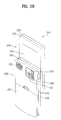
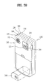
- FIG. 3A and FIG. 3B illustrate an identity device 310 that is detached from a mobile terminal 100 according to one embodiment of the present invention.
- the identity device 310 can include an SIM card.
- the identity device 310 is detachably connected to the mobile terminal 100. Therefore, a new identity device 310 can be loaded in the mobile terminal 100 by replacing an old identity device.
- the identity device 310 can be combined with the interface unit 170.
- the identity device 310 can be connected to the mobile terminal 100 by a connector separately provided for connection of the identity device.
- a connecting means (not shown) for connecting the identity device 310 to the mobile terminal 100 can be provided on the backside, lateral sides, or front side of the mobile terminal 100.
- the mobile terminal 100 can be configured to operate in a wire/wireless communication system, a satellite based communication system or a communication system capable of transmitting data carried on frames or packets.
- the mobile terminal 100 may be configured to operate within a communication system which transmits data via frames or packets, including both wireless and wireline communication systems, and satellite-based communication systems.
- Such communication systems utilize different air interfaces and/or physical layers.
- Examples of air interfaces utilized by the communication systems include frequency division multiple access (FDMA), time division multiple access (TDMA), code division multiple access (CDMA), and universal mobile telecommunications system (UMTS), the long term evolution (LTE) of the UMTS, and the global system for mobile communications (GSM).
- FDMA frequency division multiple access
- TDMA time division multiple access
- CDMA code division multiple access
- UMTS universal mobile telecommunications system
- LTE long term evolution
- GSM global system for mobile communications
- a CDMA wireless communication system includes a plurality of mobile terminals 100, a plurality of base stations (BS) 270, base station controllers (BSCs) 275, and a mobile switching center (MSC) 280.
- the MSC 280 is configured to interface with a conventional public switch telephone network (PSTN) 290 and is also configured to interface with the BSCs 275.
- PSTN public switch telephone network
- the BSCs 275 are coupled to the base stations 270 via backhaul lines that may be configured according to any of several known interfaces including, E1/T1, ATM, IP, PPP, Frame Relay, HDSL, ADSL, and xDSL.
- the system may include more than two BSCs 275.
- Each BS 270 may include one or more sectors, each sector having an omni-directional antenna or an antenna pointed in a particular direction radially away from the base station. Alternatively, each sector may include two antennas for diversity reception. Each BS 270 may be configured to support a plurality of frequency assignments, with each frequency assignment having a particular spectrum, such as 1.25 MHz or 5 MHz.
- the intersection of a sector and frequency assignment may be referred to as a CDMA channel.
- the BS 270 may also be referred to as base station transceiver subsystems (BTSs).
- BTSs base station transceiver subsystems
- the term "base station” may be used to refer collectively to a BSC 275, and one or more BS 270.
- the BS 270 may also be denoted “cell sites.” Alternatively, individual sectors of a given BS 270 may be referred to as "cell sites.”
- a terrestrial digital multimedia broadcasting (DMB) transmitter (BT) 295 broadcasts to the mobile terminals 100 operating within the system.
- the broadcast receiving module 111 shown in FIG. 1 is typically configured to receive broadcast signals transmitted by the BT 295. Similar arrangements may be implemented for other types of broadcast and multicast signaling discussed above.
- FIG. 4 further depicts several global positioning system (GPS) satellites 300.
- GPS global positioning system
- Such satellites facilitate locating the position of some or all of the mobile terminals 100. While two GPS satellites 300 are depicted in FIG. 4 , useful positioning information may be obtained with greater or fewer satellites depending on the situation.
- the position-location module 115 shown in FIG. 1 is typically configured to cooperate with the GPS satellites 300 to obtain desired position information.
- other types of position detection technology such as a location technology, may be used in addition to or instead of GPS location technology.
- some or all of the GPS satellites 300 may alternatively or additionally be configured to provide satellite DMB transmissions.
- the BS 270 receives sets of reverse-link signals from various mobile terminals 100.
- the mobile terminals 100 engage in calls, messaging, and other communications.
- Each reverse-link signal received by a given BS 270 is processed within that BS.
- the resulting data is forwarded to an associated BSC 275.
- the BSC 275 provides call resource allocation and mobility management functionality including the orchestration of soft handoffs between the BS 270.
- the BSCs 275 also route the received data to the MSC 280 which provides additional routing services for interfacing with the PSTN 290.
- the PSTN interfaces with the MSC 280
- the MSC interfaces with the BSCs 275, which in turn control the BS 270 to transmit sets of forward-link signals to the mobile terminals 100.
- the mobile terminal 100 in the following description includes at least one of the elements illustrated in FIG. 1 .
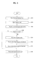
- the steps of a broadcast controlling method in a mobile terminal 100 according to the present invention are explained with reference to FIG. 5 .
- FIG. 5 illustrates a method of controlling a broadcast in a mobile terminal 100 according to one embodiment of the present invention.
- the mobile terminal 100 scans at least one frequency band using the wireless communication unit 110, and, specifically the broadcast receiving module 111 (S510).
- the mobile terminal 100 can include a separate element (not shown) for performing a frequency band scanning operation.
- a frequency band is assigned to provide a broadcast signal to the mobile terminal 100.
- a plurality of frequency bands can be assigned and at least one channel can be assigned to each of a plurality of the frequency bands.
- a channel means a broadcast channel.
- the frequency band in DVB-T can be called a channel and the channel can be called a service. It is understood that the terms 'frequency band' and 'channel' may be replaced by other terms having the same meanings.
- the scanning operation (S510) can be performed if a menu item such as 'Channel scan', corresponding to a scanning operation command for a frequency band is selected by a user through a menu search.
- the scanning operation (S510) can be performed if 'Channel scan' 1102 is selected from the menu item list illustrated in FIG. 11A .
- the wireless communication unit 110 scans all frequency bands according to a control signal from the controller 180 that corresponds to the user selection. This is called 'full scan'.
- the scanning operation (S510) can be performed if a menu item corresponding to a broadcast mode entry command is selected through a menu search or if a key separately provided for a broadcast mode entry command is selected. This can be performed if 'TV viewing' 1101 or 'Radio listening' 1104 is selected from the menu item list illustrated in FIG. 11A .
- the wireless communication unit 110 scans all frequency bands or at least one frequency band, or 'previously used frequency band', to which at least one previously used channel is assigned. The operation is performed according to a control signal from the controller 180 that corresponds to the user selection.
- the scanning operation (S510) can be performed if a menu item for a channel/program relevant data re-receiving command is selected via a menu search. This can be performed when 'Channel/program relevant data re-receiving' 1103 is selected from the menu item list illustrated in FIG. 11B .
- the wireless communication unit 110 scans all frequency bands or previously used frequency bands according to a control signal that corresponds to the user selection.
- the scanning operation (S510) can be performed when broadcast signal reception is degraded lower than a predetermined reference in the course of outputting broadcast signals.
- the mobile terminal 100 informs a user of the broadcast signal reception degradation via the output unit 150, as illustrated in FIG. 11C .
- a window is displayed via the display unit 151 to enable the user to select whether to re-receive the channel/program relevant data.
- the mobile terminal 100 scans frequency bands or the previously used frequency bands using the wireless communication unit 110 if the user selects 'Yes'.
- the wireless communication unit 110 sequentially scans all previously used frequency bands for a predetermined period of time. Alternately, the wireless communication unit 110 can scan a specific frequency among all previously used frequency bands for a predetermined period of time.
- the specific frequency band can include a frequency band to which a last used channel is assigned, a frequency band to which a user-selected channel is assigned, a frequency band selected by a user, a frequency band having a highest use frequency/rate or a frequency band having a highest preference.
- the specific frequency band is designated as the frequency band to which the last used channel is assigned for clarity and convenience of explanation.
- the wireless communication unit 110 scans all frequency bands according to a control signal from the controller 180.
- the wireless communication unit 110 scans all frequency bands or all the previously used frequency bands according to a control signal from the controller 180 if a specific previously-used frequency band, such as a frequency band to which a last used channel is assigned, is unavailable.
- the mobile terminal 100 displays an identifier via the display unit 151 to indicate that a current frequency band scan is in progress or to indicate a scan extent, as illustrated in FIG. 12A .
- the identifier may be an icon, image, a moving picture, an emoticon, a symbol, text, or a progression bar.
- Information obtained from the scanning operation (S510) can be stored in the memory 160 according to a control signal from the controller 180.
- the mobile terminal 100 selects a frequency band (S520) and receives first channel/program relevant data provided via the selected frequency band using the wireless communication unit 110 (S530).
- the channel/program relevant data is data required for reception and output of a broadcast program provided on a corresponding channel.
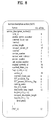
- the channel/program relevant data can include time relevant data for providing per-country/region time information such as TOT (time offset table) of DVB-T, network relevant data for providing broadcast network relevant information such as NIT (network information table), channel relevant data for providing information on a broadcast channel such as SDT (service description table), program relevant data for providing information on a channel and a program configuring the channel such as PAT (program association table), or PMT (program map table).
- TOT time offset table
- NIT network information table
- SDT service description table
- PAT program association table
- PMT program map table
- FIGS. 6 to 10 illustrate channel/program relevant data including TOT, NIT, SDT, PAT and PMT.
- the first channel/program relevant data can include at least one of this data.
- the entire channel/program relevant data includes all data required for the broadcast reception and output as well as the previously identified data.
- the first channel/program relevant data can refer to a specific one of the entire channel/program relevant data.
- the first channel/program relevant data can include a unique identification value for identifying the first channel/program relevant data from other channel/program relevant data. For example, if the identification value is a packet ID (PID), each of the channel/program relevant data can have a unique PID.
- PID packet ID
- the mobile terminal 100 is able to check whether the received channel/program relevant data is the first channel/program relevant data by using the identification value of the corresponding channel/program relevant data.
- PID of TOT is set to 20
- PID of NIT is set to 16
- PID of SDT is set to 17
- PID of PAT is set to 0 in DVB-T. Therefore, if the first channel/program relevant data is NIT, the mobile terminal 100 is able to only select channel/program relevant data having the PID of 16 from the entire channel/program relevant data provided on the selected frequency band (S520).
- the first channel/program relevant data can include unique information corresponding to the selected frequency band (S520).
- the NIT on a first frequency band can include information different from the information of the NIT on a second frequency band if the first channel/program relevant data is NIT.
- the mobile terminal 100 determines whether the first channel/program relevant data received (S530) matches the first channel/program relevant data previously stored in the memory 160 (S540).
- the determination of a match (S540) can be performed by the controller 180.
- the mobile terminal 100 is able to use the identification information included in the first channel/program relevant data to make the determination (S540).
- At least country identification information for identifying a country or time zone identification information for identifying a time zone per region is usable if the first channel/program relevant data is time relevant data such as TOT.
- time relevant data such as TOT.
- 'country_code' and 'country_region_id' can correspond to, respectively, the country identification information and the time zone identification information. Therefore, the mobile terminal 100 is able to determine its international location shift according to whether the country identification information matches and is also able to determine its interregional location shift between regions differing in time zone according to whether the time zone identification information matches.
- At least network identification information for identifying a broadcast network or transport stream identification information for identifying information provided per channel is usable if the channel/program relevant data is network relevant data such as NIT.
- network relevant data such as NIT.
- 'network_id' and 'transport_stream_id' can correspond to, respectively, the network identification information and the transport stream identification information, respectively. Therefore, the mobile terminal 100 is able to determine a broadcast network change according to whether the network identification information matches and is also able to determine a channel switching according to whether the transport stream identification information matches.
- At least channel identification information for identifying a broadcast channel or transport stream identification information is usable if the first channel/program relevant data is channel relevant data such as SDT.
- channel relevant data such as SDT.
- 'service_id' and 'transport_stream_id' can correspond to, respectively, the channel identification information and the transport stream identification information. Therefore, the mobile terminal 100 is able to determine a channel switching according to whether the channel identification information matches or the transport stream identification information matches.
- At least channel identification information, program identification information for identifying a broadcast program or program configuration signal identification information for identifying video, audio and data signals configuring the broadcast program is usable if the first channel/program relevant data is program relevant data such as PAT or PMT.
- program relevant data such as PAT or PMT.
- 'transport_stream_id' corresponds to the program identification information
- 'program_number' or 'program_map_PID' may correspond to the program identification information.
- 'stream_type' or 'elementary_PID' can correspond to the program configuration signal identification information. Therefore, the mobile terminal 100 is able to determine a broadcast program change of a specific channel according to whether the program configuration signal identification information matches.
- the mobile terminal 100 While performing the determination (S540), the mobile terminal 100 displays an identifier via the display unit 151 to indicate that a determination of a match of the first channel/program relevant information is in progress or an identifier indicating an extent of the determination, as illustrated in FIG. 12B .
- the identifier may be an icon, an image, a moving picture, an emoticon, a symbol, text, or a progression bar.
- the absence of a match of the first channel/program relevant data according to the determination (S540) indicates a location change of the mobile terminal 100, a channel switching per frequency band of the mobile terminal, or a program change per channel of the mobile terminal. This may mean that broadcast viewing via the mobile terminal 100 is not available. In the absence of a match of the first channel/program relevant data, it is necessary to update the channel/program relevant data previously stored in the memory 160 entirely or in part in order to smoothly perform broadcast viewing via the mobile terminal 100 at a current location.
- the mobile terminal 100 Upon determining the absence of a match as a result of the determination (S540), the mobile terminal 100 scans entire frequency bands using the broadcast relieving module 111 or an element (not shown) separately provided for the frequency band scan (S550).
- the entire frequency bands may refer to all the frequency bands assigned to provide broadcast signals to the mobile terminal 100.
- the mobile terminal 100 receives entire channel/program relevant data using the wireless communication unit 110 (S560) as a result of the scan of entire frequency bands.
- entire channel/program relevant data is acquired through the scan performed on the entire frequency bands since the channel/program relevant data may include information differing according to frequency band.
- Receiving entire channel/program relevant data (S560) can be performed by the broadcast receiving module 111 or the element (not shown) separately provided for the frequency band scan according to a control signal from the controller 180.
- the mobile terminal 100 updates the entire or partial first channel/program relevant data previously stored in the memory 160 (S570).
- the updating operation (S570) can be performed by the controller 180.
- the updating operation (S570) can be performed upon receiving an operation corresponding to an update command from a user or according to a determination made by the mobile terminal 100. Alternatively, the update operation (S570) can be automatically performed upon receiving the entire channel/program relevant data.
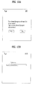
- the mobile terminal 100 outputs text to the display unit 151 for querying whether to update the previously stored channel/program relevant data with reference to the received entire channel/program relevant data, as illustrated in FIG. 13A . If a user selects to update the entire channel/program relevant data by selecting 'Yes', the mobile terminal 100 performs the update operation (S570).
- the mobile terminal 100 While performing the update operation (S570), the mobile terminal 100 displays an identifier on the display unit 151 to indicate that the update of the channel/program relevant information is in progress or an identifier indicating an extent of the update, as illustrated in FIG. 13B .
- the identifier may be an icon, an image, a moving picture, an emoticon, a symbol, text, or a progression bar.
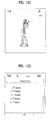
- the mobile terminal 100 receives and outputs a broadcast signal provided on a specific broadcast channel using the updated channel/program relevant data (S580). For example, the mobile terminal 100 outputs a broadcast signal received on a broadcast channel selected by a user or a broadcast signal received on a broadcast channel randomly selected by the mobile terminal 100, as illustrated in FIG. 13C .
- the mobile terminal 100 displays a channel list with reference to the updated channel/program relevant data if a user selects a menu item corresponding to 'channel list view', as illustrated in FIG. 13D .
- the mobile terminal 100 determines a match (S540), the mobile terminal then receives and outputs a broadcast signal provided on a specific broadcast channel using the channel/program relevant data previously stored in the memory 160 (S580). For example, the mobile terminal 100 outputs a broadcast signal received on a broadcast channel selected by a user, a broadcast channel randomly selected by the mobile terminal 100 or a last used broadcast channel, as illustrated in FIG. 14A . If a user selects a menu item corresponding to 'channel list view', the mobile terminal 100 displays a channel list based on the previously stored channel/program relevant data, as illustrated in FIG. 14B .
- the mobile terminal 100 sequentially performs the method illustrated in FIG. 5 .
- the method of controlling a broadcast in a mobile terminal according to the present invention can be implemented in a program recorded medium as computer-readable codes.
- the computer-readable media include all types of recording devices in which data readable by a computer system are stored.
- the computer-readable media include ROM, RAM, CD-ROM, magnetic tapes, floppy discs, and optical data storage devices, and also include carrier-wave type implementations such as transmission via Internet.
- the computer can include the controller 180 of the mobile terminal 100.
- the present invention provides several advantages. First, the present invention is able to update previously stored channel/program relevant data quickly and conveniently. Second, the present invention is able to determine whether to update entire channel/program relevant data by determining a presence or absence of matching partial data among previously stored channel/program relevant data, thereby providing convenience to a user because a one-by-one user selection operation is unnecessary.
- the present invention can take the form of an entirely hardware embodiment, an entirely software embodiment or an embodiment containing both hardware and software elements.
- a software embodiment may include, but not be limited to, firmware, resident software, and microcode.
- the invention can take the form of a computer program product accessible from a computer-usable or computer-readable medium providing program code for use by or in connection with a computer or any instruction execution system.
- a computer-usable or computer readable medium can be any apparatus that can contain, store, communicate, propagate, or transport the program for use by or in connection with the instruction execution system, apparatus, or device.
- a data processing system suitable for storing and/or executing program code will include at least one processor coupled directly or indirectly to memory elements through a system bus.
- the memory elements can include local memory employed during actual execution of the program code, bulk storage, and cache memories which provide temporary storage of at least some program code in order to reduce the number of times code must be retrieved from bulk storage during execution.
- I/O devices including, but not limited to, keyboards, displays, and pointing devices, can be coupled to the system either directly or through intervening I/O controllers.
- Network adapters such as a modem, a cable modem, or an Ethernet card, may also be coupled to the system to enable the data processing system to become coupled to other data processing systems or remote printers or storage devices through intervening private or public networks.
- logic code programs, modules, processes, methods, and the order in which the respective elements of each method are performed are purely exemplary. Depending on the implementation, they may be performed in any order or in parallel, unless indicated otherwise in the present disclosure. Further, the logic code is not related, or limited to, any particular programming language, and may be comprise one or more modules that execute on one or more processors in a distributed, non-distributed, or multiprocessing environment.
- the method as described herein may be used in the fabrication of integrated circuit chips.
- the resulting integrated circuit chips can be distributed by the fabricator in raw wafer form as a single wafer that has multiple unpackaged chips, as a bare die, or in a packaged form.
- the chip is mounted in a single chip package, such as a plastic carrier with leads that are affixed to a motherboard or other higher level carrier or in a multi-chip package, such as a ceramic carrier that has either or both surface interconnections of buried interconnections.
- the chip is then integrated with other chips, discrete circuit elements, and/or other signal processing devices as part of either an intermediate product, such as a motherboard or an end product.
- the end product can be any product that includes integrated circuit chips, ranging from toys and other low-end applications to advanced computer products having a display, a keyboard or other input device, and a central processor.
Landscapes
- Engineering & Computer Science (AREA)
- Signal Processing (AREA)
- Multimedia (AREA)
- Computer Security & Cryptography (AREA)
- Databases & Information Systems (AREA)
- General Engineering & Computer Science (AREA)
- Computer Networks & Wireless Communication (AREA)
- Telephone Function (AREA)
- Mobile Radio Communication Systems (AREA)
Abstract
Description
- This application claims the right of priority to Korean Application No.
10-2008-0059223, filed on June 23, 2008 - The present invention is directed to a mobile terminal, and more particularly, to a mobile terminal and method of controlling a broadcast in a mobile terminal. Although the present invention is suitable for a wide scope of applications, it is particularly suitable for a mobile terminal having a broadcast receiving function.
- A mobile terminal is a device which may be configured to perform various functions. Examples of such functions include data and voice communications, capturing images and video via a camera, recording audio, playing music files via a speaker system, and displaying images and video on a display. Some mobile terminals include additional functionality which supports game playing, while other mobile terminals are configured as multimedia players. More recently, mobile terminals have been configured to receive broadcast and multicast signals which permit viewing of content such as videos and television programs.
- Efforts are ongoing to support and increase the functionality of mobile terminals. Such efforts include software and hardware improvements, as well as changes and improvements in the structural components which form the mobile terminal.
- In a conventional broadcast receiving terminal, at least one frequency band having at least one assigned channel is scanned when initially entering a broadcast mode or receiving a user selection operation. It is then possible to perform a broadcast receiving operation and a broadcast outputting operation using channel/program relevant data obtained as a result of the scan.
- The broadcast receiving terminal establishes a database of the channel/program relevant data obtained as a result of the scan. The broadcast receiving terminal performs the broadcast receiving and outputting operations using the stored channel/program relevant data when entering a broadcast mode.
- The broadcast receiving terminal is able perform a frequency band scan operation according to a selection made by a user if broadcast receiving and outputting operations using the stored channel/program relevant data are impossible. The broadcast receiving terminal is then able to perform the broadcast receiving and outputting operations using channel/program relevant data obtained as a result of the frequency band scan operation. However, the conventional broadcast receiving terminal needs each user selection operation to update previously stored channel/program relevant data.
- A scheme for updating channel/program relevant data according to a presence or absence of modifications of previously stored channel/program relevant data has not been provided when the broadcast receiving and outputting operations are impossible. A scheme for updating channel/program relevant data by determining a presence or absence of modifications of previously stored channel/program relevant data in a simple manner is needed.
- In one aspect of the present invention, a mobile terminal having a broadcast receiving feature is provided. The mobile terminal includes a memory for storing channel/program relevant data, a wireless communication unit for receiving first channel/program relevant data and a controller for determining whether the received first channel/program relevant data matches first channel/program relevant data stored in the memory, controlling the wireless communication unit to receive entire channel/program relevant data if the received first channel/program relevant data does not match the stored first channel/program relevant data, and updating the stored first channel/program relevant data with reference to the received entire channel/program relevant data.
- It is contemplated that the wireless communication unit scans one or more frequency bands and the controller selects a frequency band for providing the first channel/program relevant data from the scanned one or more frequency bands. It is further contemplated that the controller selects a first scanned frequency band, a frequency band having best signal strength or a user selected frequency band from the one or more scanned frequency bands.
- It is contemplated that the wireless communication unit scans a last frequency band to which a last used channel among one or more previously-used channels is assigned and the controller selects the last frequency band as the frequency band for providing the first channel/program relevant data if the last frequency band is available and the controller controls the wireless communication unit to scan the one or more other frequency bands if the last frequency band is not available. It is further contemplated that the wireless communication unit scans the one or more frequency bands to which at least one previously-used channel is assigned according to a control signal from the controller.
- It is contemplated that the controller controls the wireless communication unit to scan the entire frequency bands if the one or more frequency bands to which the at least one previously-used channel is assigned is not available. It is further contemplated that the controller controls the wireless communication unit to perform a scan operation on the one or more frequency bands if at least broadcast mode entry, a user selection operation input or unavailable broadcast viewing is determined.
- It is contemplated that the controller determines whether the received first channel/program relevant data matches the stored first channel/program relevant data by using identification information included in the received first channel/program relevant data. It is further contemplated that the identification information includes at least country identification information or time zone identification information if the received first channel/program relevant data is time relevant data, the identification information includes at least network identification information or transport stream identification information if the received first channel/program relevant data is network relevant data, the identification information includes channel identification information or transport stream identification information if the received first channel/program relevant data is channel relevant data and the identification information includes channel identification information, program identification information or program configuration data identification information, if the received first channel/program relevant data is program relevant data.
- It is contemplated that the wireless communication unit scans entire frequency bands and receives the entire channel/program relevant data according to a control signal from the controller if the received first channel/program relevant data does not match the stored first channel/program relevant data. It is further contemplated that the mobile terminal further includes a user input unit for receiving a selection from a user and wherein the controller determines whether to update the stored first channel/program relevant data according to the received user selection.
- It is contemplated that the received first channel/program relevant data includes unique information for a frequency band providing the first channel/program relevant data. It is further contemplated that the received first channel/program relevant data includes a unique identification value for identifying the received channel/program relevant data.
- In another aspect of the present invention, a method of controlling a broadcast in a mobile terminal is provided. The method includes receiving first channel/program relevant data in the mobile terminal, determining whether the received first channel/program relevant data matches stored first channel/program relevant data and receiving entire channel/program relevant data if the received first channel/program relevant data does not match the stored first channel/program relevant data and updating the stored first channel/program relevant data with reference to the received entire channel/program relevant data.
- It is contemplated that the method further includes scanning one or more frequency bands and selecting a frequency band for providing the first channel/program relevant data from the one or more scanned frequency bands. It is further contemplated that scanning the one or more frequency bands includes scanning a last frequency band to which a last used channel among one or more previously-used channels is assigned, selecting the frequency band includes selecting the last frequency band as the frequency band for providing the first channel/program relevant data if the last frequency band is available, and the method further includes scanning one or more other frequency bands if the last frequency band is not available.
- It is contemplated that scanning the one or more frequency bands includes scanning at least one frequency band to which at least one previously-used channel is assigned. It is further contemplated that the method further includes scanning the entire frequency bands if the at least one frequency band to which the at least one previously-used channel is assigned is not available.
- It is contemplated that scanning the one or more frequency bands is performed upon detecting a broadcast mode entry, a user selection operation input or unavailable broadcast viewing. It is further contemplated that determining whether the received first channel/program relevant data matches the stored first channel/program relevant data includes using identification information included in the received first channel/program relevant data.
- It is contemplated that the new identification information includes at least country identification information or time zone identification information if the received first channel/program relevant data is time relevant data, the identification information includes at least network identification information or transport stream identification information if the received first channel/program relevant data is network relevant data, the identification information includes at least channel identification information or transport stream identification information if the received first channel/program relevant data is channel relevant data and the identification information includes at least channel identification information, program identification information or program configuration data identification information if the received first channel/program relevant data is program relevant data. It is further contemplated that the method further includes scanning entire frequency bands if the received first channel/program relevant data does not match the stored first channel/program relevant data, wherein the entire channel/program relevant data are obtained as a result of scanning the entire frequency bands. Preferably, the method further includes receiving a selection operation from a user, wherein updating the stored first channel/program relevant data includes updating the stored first channel/program relevant data according to the received selection operation.
- Additional features and advantages of the invention will be set forth in the description which follows, and in part will be apparent from the description, or may be learned by practice of the invention. It is to be understood that both the foregoing general description and the following detailed description of the present invention are exemplary and explanatory and are intended to provide further explanation of the invention as claimed.
- These and other embodiments will also become readily apparent to those skilled in the art from the following detailed description of the embodiments having reference to the attached figures, the invention not being limited to any particular embodiments disclosed.
- The accompanying drawings, which are included to provide a further understanding of the invention and are incorporated in and constitute a part of this specification, illustrate embodiments of the invention and together with the description serve to explain the principles of the invention. Features, elements, and aspects of the invention that are referenced by the same numerals in different figures represent the same, equivalent, or similar features, elements, or aspects in accordance with one or more embodiments.
-
FIG.1 illustrates a block diagram of a mobile terminal in accordance with an embodiment of the present invention. -
FIG. 2A illustrates a perspective view of a front side of a mobile terminal according to an embodiment of the present invention. -
FIG. 2B illustrates a rear view of the mobile terminal illustrated inFIG. 2A . -
FIG. 3A andFIG. 3B are perspective diagrams illustrating an identity device that is detached from a terminal according to one embodiment of the present invention. -
FIG. 4 is a block diagram of a CDMA wireless communication system operable with the mobile terminal of the present invention. -
FIG. 5 illustrates a method of controlling a broadcast in a mobile terminal according to one embodiment of the present invention. -
FIGS. 6 to 10 illustrate first channel/program relevant data according to one embodiment of the present invention. -
FIG. 11A illustrates a screen configuration for a broadcast mode entry according to one embodiment of the present invention. -
FIG. 11B illustrates a screen configuration for a user selection input according to one embodiment of the present invention. -
FIG. 11C illustrates a screen configuration for an unavailable broadcast viewing in a mobile terminal according to one embodiment of the present invention. -
FIG. 12A illustrates a screen configuration for a frequency scan in a mobile terminal according to one embodiment of the present invention. -
FIG. 12B illustrates a screen configuration for determining a presence or absence of channel/program relevant data matching in a mobile terminal according to one embodiment of the present invention. -
FIGS. 13A to 13D illustrate screen configurations for an absence of channel/program relevant data matching in a mobile terminal according to one embodiment of the present invention. -
FIGS. 14A to 14C illustrate screen configurations for a presence of channel/program relevant data matching in a mobile terminal according to one embodiment of the present invention. - Reference will now be made in detail to the preferred embodiments of the present invention, examples of which are illustrated in the accompanying drawings. It is to be understood by those of ordinary skill in this technological field that other embodiments may be utilized, and structural, electrical, as well as procedural changes may be made without departing from the scope of the present invention. Wherever possible, the same reference numbers will be used throughout the drawings to refer to the same or like parts.
-
Fig. 1 is a block diagram ofmobile terminal 100 in accordance with an embodiment of the present invention. Themobile terminal 100 may be implemented using a variety of different types of terminals. Examples of such terminals include mobile phones, user equipment, smart phones, computers, digital broadcast terminals, personal digital assistants, portable multimedia players (PMP) and navigators. - By way of non-limiting example only, further description will be with regard to a
mobile terminal 100. However, such teachings apply equally to other types of terminals.FIG. 1 shows themobile terminal 100 having various components, but it is understood that implementing all of the illustrated components is not a requirement. Greater or fewer components may alternatively be implemented. -
Fig. 1 illustrates awireless communication unit 110 configured with several commonly implemented components. For example, thewireless communication unit 110 typically includes one or more components that permit wireless communication between themobile terminal 100 and a wireless communication system or network within which the mobile terminal is located. - The
broadcast receiving module 111 receives a broadcast signal and/or broadcast associated information from an external broadcast managing entity via a broadcast channel. The broadcast channel may include a satellite channel or a terrestrial channel. The broadcast managing entity refers generally to a system that transmits a broadcast signal and/or broadcast associated information. - Examples of broadcast associated information include information associated with a broadcast channel, a broadcast program, and a broadcast service provider. For example, the broadcast associated information may include an electronic program guide (EPG) of digital multimedia broadcasting (DMB) and electronic service guide (ESG) of digital video broadcast-handheld (DVB-H).
- The broadcast signal may be implemented, for example, as a TV broadcast signal, a radio broadcast signal, or a data broadcast signal. The broadcast signal may further include a broadcast signal combined with a TV or radio broadcast signal.
- The
broadcast receiving module 111 may be configured to receive broadcast signals transmitted from various types of broadcast systems. By way of non-limiting examples, such broadcasting systems include digital multimedia broadcasting-terrestrial (DMB-T), digital multimedia broadcasting-satellite (DMB-S), digital video broadcast-handheld (DVB-H), the data broadcasting system known as media forward link only (MediaFLO®) and integrated services digital broadcast-terrestrial (ISDB-T). - Receiving multicast signals is also possible. Data received by the
broadcast receiving module 111 may be stored in a suitable device, such as thememory 160. - The
mobile communication module 112 communicates wireless signals with one or more network entities, such as base station or Node-B. Such signals may represent, for example, audio, video, multimedia, control signaling, or data. - The
wireless Internet module 113 supports Internet access for themobile terminal 100. Thewireless Internet module 113 may be internally or externally coupled to themobile terminal 100. - The short-
range communication module 114 facilitates relatively short-range communications. Suitable technologies for short-range communication may include, but are not limited to, radio frequency identification (RFID), infrared data association (IrDA), ultra-wideband (UWB), as well at the networking technologies commonly referred to as Bluetooth® and ZigBee®. - The position-
location module 115 identifies or otherwise obtains the location of themobile terminal 100. The position-location module 115 may be implemented using global positioning system (GPS) components that cooperate with associated satellites, network components, and combinations thereof. - The audio/video (AN)
input unit 120 is configured to provide audio or video signal input to themobile terminal 100. As illustrated, the ANinput unit 120 includes acamera 121 and amicrophone 122. If desired, two ormore microphones 122 and/orcameras 121 may be used. - The
camera 121 receives and processes image frames of still pictures or video. Themicrophone 122 receives an external audio signal while themobile terminal 100 is in a particular mode, such as phone call mode, recording mode or voice recognition. This audio signal is processed and converted into digital data. - The
mobile terminal 100, and specifically the A/V input unit 120, may include assorted noise removing algorithms to remove noise generated in the course of receiving the external audio signal. Data generated by the A/V input unit 120 may be stored in thememory 160, utilized by theoutput unit 150, or transmitted via one or more modules of thecommunication unit 110. - The
user input unit 130 generates input data responsive to user manipulation of an associated input device or devices. Examples of such devices include a keypad, a dome switch, a touchpad such as static pressure/capacitance, a jog wheel and a jog switch. A specific example is one in which theuser input unit 130 is configured as a touchpad in cooperation with a touch screen display, which will be described in more detail later. - The
sensing unit 140 provides status measurements of various aspects of themobile terminal 100. For example, thesensing unit 140 may detect an open/close status of themobile terminal 100, the relative positioning of components such as a display and keypad, a change of position of the mobile terminal or a component of the mobile terminal, a presence or absence of user contact with the mobile terminal, orientation or acceleration/deceleration of the mobile terminal - The
mobile terminal 100 may be configured as a slide-type mobile terminal and thesensing unit 140 may sense whether a sliding portion of the mobile terminal is open or closed. Thesensing unit 140 may also sense the presence or absence of power provided by thepower supply 190 or the presence or absence of a coupling or other connection between theinterface unit 170 and an external device. - The
interface unit 170 may be implemented to couple themobile terminal 100 with external devices. Typical external devices include wired/wireless headphones, external chargers, power supplies, earphones, microphones and storage devices configured to store data such as audio, video and pictures. Theinterface unit 170 may be configured using a wired/wireless data port, a card socket for coupling to a memory card, a device equipped with an identity module, audio input/output ports or video input/output ports. - The identity module is a chip that stores various types of information for identifying or authenticating use authority of the terminal 100. The identity module can include a user identity module (UIM), a subscriber identity module (SIM), or a universal subscriber identity module (USIM). Specifically, the identity module can include a module for identifying or authenticating authority for a broadcast purchase and/or broadcast viewing using the
terminal 100. - A device provided with the identity module, referred to as an identity device, can be manufactured as a smart card. The identity device can be connected to the terminal 100 via a port for connecting the identity device.
- The
output unit 150 may include various components that support the output requirements of themobile terminal 100. Thedisplay 151 may be implemented to visually display information associated with themobile terminal 100. - In one example, the
display 151 may provide a user interface or graphical user interface that includes information associated with placing, conducting, and terminating a phone call if themobile terminal 100 is operating in a phone call mode. As another example, thedisplay 151 may additionally or alternatively display images that are associated with a video call mode or a photographing mode. - One particular implementation of the present invention includes the
display 151 configured as a touch screen working in cooperation with an input device, such as a touchpad. This configuration permits thedisplay 151 to function both as an output device and an input device. - The
display 151 may be implemented using known display technologies including a liquid crystal display (LCD), a thin film transistor-liquid crystal display (TFT-LCD), an organic light-emitting diode display (OLED), a flexible display and a three-dimensional display. Themobile terminal 100 may include one ormore displays 151. An example of a two-display embodiment is one in which onedisplay 151 is configured as an internal display viewable when the terminal is in an opened position and asecond display 151 configured as an external display viewable in both the open and closed positions. - A proximity sensor (not shown) can be provided within the touch screen or around the touch screen. Alternatively, the proximity sensor can be provided within the
sensing unit 140. - The proximity sensor is a sensor that detects a presence or absence of an object approaching a prescribed detecting surface or an object existing around the proximity sensor using an electromagnetic field strength or infrared ray without mechanical contact. Therefore, the proximity sensor has longer durability than a contact type sensor and also has wider utility than the contact type sensor. The proximity sensor can include a transmittive photoelectric sensor, a direct reflective photoelectric sensor, a mirror reflective photoelectric sensor, a radio frequency oscillation proximity sensor, an electrostatic capacity proximity sensor, a magnetic proximity sensor, or an infrared proximity sensor.
- For example, in a radio frequency oscillation proximity sensor, if an object approaches in the vicinity of the sensor detecting surface while an oscillation circuit is oscillating a full-wave radio frequency, the oscillation amplitude of the oscillation circuit attenuates or stops. This variation is converted to an electric signal in order to detect a presence or absence of the object. Therefore, the proximity sensor is able to detect a specific object without interference even if a substance other than a metallic substance is placed between the radio frequency oscillation proximity sensor and the object.
- If the proximity sensor is provided with an electrostatic type touch screen, the proximity sensor can be configured to detect proximity of a pointer using a variation of an electric field according to the proximity of the pointer. In this way, the proximity sensor is able to detect the position of a pointer and the distance between the pointer and the touch screen if the pointer is located in the vicinity of the touch screen despite not contacting the touch screen.
- For clarity, when a pointer approaches without contacting the touch screen and is recognized as located on the touch screen, this is named 'proximity touch'. When the pointer actually touches the touch screen is called a 'contact touch'. The position on the touch screen that is proximity-touched by the pointer refers to the position of the pointer which vertically opposes the touch screen when the pointer performs the proximity touch.
- The proximity sensor detects a proximity touch and a proximity touch pattern such as a proximity touch distance, a proximity touch duration, a proximity touch position, or a proximity touch shift state. Information corresponding to the detected proximity touch and the detected proximity touch pattern can be output to the touch screen.
-
FIG.1 further illustrates theoutput unit 150 having anaudio output module 152, which supports the audio output requirements of themobile terminal 100. Theaudio output module 152 may be implemented using one or more speakers, buzzers, other audio producing devices, or combinations thereof. - The
audio output module 152 functions in various modes such as call-receiving mode, call-placing mode, recording mode, voice recognition mode and broadcast reception mode. Theaudio output module 152 outputs audio relating to a particular function or status, such as call received, message received, or errors. - The
output unit 150 is further illustrated having analarm 153, which may signal or otherwise identify the occurrence of a particular event associated with themobile terminal 100. Typical events include call received, message received and user input received. - An example of a signal provided by the
output unit 150 is a tactile sensation. For example, thealarm 153 may be configured to vibrate responsive to themobile terminal 100 receiving a call or message. As another example, vibration may be provided by thealarm 153 responsive to receiving user input at themobile terminal 100 in order to provide a tactile feedback mechanism. It is understood that the various signals provided by the components ofoutput unit 150 may be separately performed or performed using any combination of the components. - The
memory 160 is generally used to store various types of data to support the processing, control, and storage requirements of themobile terminal 100. Examples of such data include program instructions for applications operating in themobile terminal 100, contact data, phonebook data, messages, pictures, and video. - The
memory 160 illustrated inFIG. 1 may be implemented using any type or combination of suitable volatile and non-volatile memory or storage devices. Examples of memory types are random access memory (RAM), static random access memory (SRAM), electrically erasable programmable read-only memory (EEPROM), erasable programmable read-only memory (EPROM), programmable read-only memory (PROM), read-only memory (ROM), magnetic memory, flash memory, magnetic or optical disk memory, card-type memory, and other similar memory or data storage devices. - The
memory 160 may store map data for searching and guiding the travel route of themobile terminal 100 if the mobile terminal is mounted in a mobile object. The mobile object may not only be mobile means, such as a passenger car, subway or bicycle that can be mounted with themobile terminal 100 or into which a user holding the mobile terminal may be located, but also may be a user when the user holds the mobile terminal and moves. - The
controller 180 typically controls the overall operations of themobile terminal 100. For example, thecontroller 180 performs the control and processing associated with voice calls, data communications, instant message communication, video calls, camera operations and recording operations. Thecontroller 180 is able to perform pattern recognition processing for recognizing a handwriting input performed on the touch screen as a character or recognizing a picture drawing input performed on the touch screen as an image - The
controller 180 may include amultimedia module 181 that provides multimedia playback. Themultimedia module 181 may be configured as part of thecontroller 180 or implemented as a separate component. - The
power supply 190 provides power required by the various components for themobile terminal 100. The power may be internal power, external power, or combinations thereof. - Various embodiments described herein may be implemented in various ways. For example, the embodiments may be implemented in a computer-readable medium using computer software, hardware, or some combination thereof.
- For a hardware implementation, the embodiments described may be implemented within one or more application specific integrated circuits (ASICs), digital signal processors (DSPs), digital signal processing devices (DSPDs), programmable logic devices (PLDs), field programmable gate arrays (FPGAs), processors, controllers, micro-controllers, microprocessors, other electronic units designed to perform the functions described herein, or a selective combination thereof. The
controller 180 may also implement such embodiments. - For a software implementation, the embodiments described herein may be implemented with separate software modules, such as procedures and functions, each of which perform one or more of the functions and operations described herein. The software codes can be implemented with a software application written in any suitable programming language and may be stored in memory, such as the
memory 160, and executed by a controller or processor, such as thecontroller 180. - The
mobile terminal 100 may be implemented in a variety of different configurations. Examples of such configurations include folder-type, slide-type, bar-type, rotational-type, swing-type and combinations thereof. For clarity, further disclosure will primarily relate to a slide-typemobile terminal 100. However, such teachings apply equally to other types ofmobile terminals 100. -
FIG. 2A is a perspective view of a front side of amobile terminal 100 according to an embodiment of the present invention. InFIG. 2A , themobile terminal 100 is illustrated having afirst body 200 configured to slidably cooperate with asecond body 205. - The user input unit 130 (described in
FIG. 1 ) is implemented usingfunction keys 210 and akeypad 215. Thefunction keys 210 are located on thefirst body 200 and thekeypad 215 is located on thesecond body 205. Thekeypad 215 includes various keys, such as numbers, characters, and symbols to enable a user to place a call, prepare a text or multimedia message, or otherwise operate themobile terminal 100. - The
user input unit 130 may be implemented using one or more dome switches or touch pads that can receive a user command or information according to a press or touch operation by the user. Theuser input unit 130 may also be implemented using a mechanical manipulation means, such as a rotatable element, such as a wheel, dial, jog button, or thumbwheel, or a linear element, such as a joystick, lever, or knob. - The
first body 200 slides relative to thesecond body 205 between open and closed positions. Thefirst body 200 is positioned over thesecond body 205 in the closed position such that thekeypad 215 is substantially or completely obscured by the first body. User access to thekeypad 215, thedisplay 151 and thefunction keys 210 is facilitated in the open position. Thefunction keys 210 are conveniently configured for a user to enter commands, such as start, stop and scroll. - The
mobile terminal 100 is operable in either a standby mode or an active call mode. Themobile terminal 100 is able to receive a call or message and to receive and respond to network control signaling in the standby mode. - The
mobile terminal 100 typically operates in the standby mode in the closed position and in the active mode in the open position. This mode configuration may be changed as required or desired. - The
first body 200 is illustrated as formed of afirst case 220 and asecond case 225. Thesecond body 205 is illustrated as formed of afirst case 230 and asecond case 235. Thefront case 220 andsecond case 225 of thefirst body 200 and thefirst case 230 andsecond case 235 or thesecond body 205 are usually formed of a suitably rigid material, such as injection molded plastic, or formed using metallic material, such as stainless steel (STS) and titanium (Ti). - One or more intermediate cases may be provided between the
first case 220 andsecond case 225 of thefirst body 200 or between thefirst case 230 andsecond case 235 of thesecond body 205. Thefirst body 200 andsecond body 205 are typically sized to receive electronic components necessary to support operation of themobile terminal 100. - The
first body 200 is illustrated as having acamera 121 andaudio output module 152, which is configured as a speaker positioned relative to thedisplay 151. Thecamera 121 may be constructed such that it can be selectively positioned relative tofirst body 200 by rotation or swiveling. - The
function keys 210 are positioned adjacent to a lower side of thedisplay 151, which is shown implemented as an LCD or OLED. Thedisplay 151 may also be configured as a touch screen having an underlying touchpad which generates signals responsive to user contact with the touch screen with a finger or stylus. - The
second body 205 is illustrated as having amicrophone 122 positioned adjacent to thekeypad 215 and havingside keys 245, which are one type of user input unit, positioned along the side of the second body. Preferably, theside keys 245 are configured as hot keys associated with a particular function of themobile terminal 100. - An
interface unit 170 is illustrated as positioned adjacent to theside keys 245. Apower supply 190 in a form of a battery is illustrated as located on a lower portion of thesecond body 205. -
FIG. 2B is a rear view of the mobile terminal illustrated inFIG. 2A .FIG. 2B illustrates thesecond body 205 having acamera 121 with an associatedflash 250 andmirror 255. Theflash 250 operates in conjunction with thecamera 121. Themirror 255 is useful for assisting a user to position thecamera 121 in a self-portrait mode. - The
camera 121 of thesecond body 205 illustrated inFIG. 2B faces a direction opposite to a direction faced by thecamera 121 of thefirst body 200 illustrated inFIG. 2A . Each of thecameras 121 of thefirst body 200 andsecond body 205 may have the same or different capabilities. - The
camera 121 of thefirst body 200 in one embodiment operates with a relatively lower resolution than thecamera 121 of thesecond body 205. Such an arrangement works well during a videoconference, for example, in which reverse link bandwidth capabilities may be limited. The relatively higher resolution of thecamera 121 of thesecond body 205 is useful for obtaining higher quality pictures for later use or for communicating with other parties. - The
second body 205 illustrated inFIG. 2B also includes anaudio output module 152 located on an upper side of the second body and configured as a speaker. Theaudio output modules 152 of thefirst body 200 andsecond body 205 may cooperate to provide stereo output. Moreover, either or both of theseaudio output modules 152 may be configured to operate as a speakerphone. - A broadcast
signal receiving antenna 260 is illustrated as located at an upper end of thesecond body 205 inFIG. 2B . Theantenna 260 functions in cooperation with thebroadcast receiving module 111 illustrated inFIG. 1 . Theantenna 260 may be fixed or retractable into thesecond body 205. - The rear side of the
first body 200 includes aslide module 265. Theslide module 265 slidably couples with a corresponding slide module located on the front side of thesecond body 205. - It is understood that the arrangement of the various components of the
first body 200 andsecond body 205 illustrated inFIGS. 2A and2B may be modified as required or desired. For example, some or all of the components of one body may alternatively be implemented on the other body. Further, the location and relative positioning of the components are not critical and, therefore, the components may be positioned at locations that differ from those illustrated inFIGS. 2A and2B . -
FIG. 3A andFIG. 3B illustrate anidentity device 310 that is detached from amobile terminal 100 according to one embodiment of the present invention. Theidentity device 310 can include an SIM card. - Referring to
FIGS. 3A andFIG. 3B , theidentity device 310 is detachably connected to themobile terminal 100. Therefore, anew identity device 310 can be loaded in themobile terminal 100 by replacing an old identity device. Optionally, theidentity device 310 can be combined with theinterface unit 170. - The
identity device 310 can be connected to themobile terminal 100 by a connector separately provided for connection of the identity device. A connecting means (not shown) for connecting theidentity device 310 to themobile terminal 100 can be provided on the backside, lateral sides, or front side of themobile terminal 100. - The
mobile terminal 100 can be configured to operate in a wire/wireless communication system, a satellite based communication system or a communication system capable of transmitting data carried on frames or packets. Themobile terminal 100 may be configured to operate within a communication system which transmits data via frames or packets, including both wireless and wireline communication systems, and satellite-based communication systems. Such communication systems utilize different air interfaces and/or physical layers. - Examples of air interfaces utilized by the communication systems include frequency division multiple access (FDMA), time division multiple access (TDMA), code division multiple access (CDMA), and universal mobile telecommunications system (UMTS), the long term evolution (LTE) of the UMTS, and the global system for mobile communications (GSM). By way of non-limiting example only, further description will relate to a CDMA communication system, but such teachings apply equally to other system types.
- Referring to
FIG. 4 , a CDMA wireless communication system includes a plurality ofmobile terminals 100, a plurality of base stations (BS) 270, base station controllers (BSCs) 275, and a mobile switching center (MSC) 280. TheMSC 280 is configured to interface with a conventional public switch telephone network (PSTN) 290 and is also configured to interface with theBSCs 275. TheBSCs 275 are coupled to thebase stations 270 via backhaul lines that may be configured according to any of several known interfaces including, E1/T1, ATM, IP, PPP, Frame Relay, HDSL, ADSL, and xDSL. The system may include more than twoBSCs 275. - Each
BS 270 may include one or more sectors, each sector having an omni-directional antenna or an antenna pointed in a particular direction radially away from the base station. Alternatively, each sector may include two antennas for diversity reception. EachBS 270 may be configured to support a plurality of frequency assignments, with each frequency assignment having a particular spectrum, such as 1.25 MHz or 5 MHz. - The intersection of a sector and frequency assignment may be referred to as a CDMA channel. The
BS 270 may also be referred to as base station transceiver subsystems (BTSs). - In some cases, the term "base station" may be used to refer collectively to a
BSC 275, and one ormore BS 270. TheBS 270 may also be denoted "cell sites." Alternatively, individual sectors of a givenBS 270 may be referred to as "cell sites." - A terrestrial digital multimedia broadcasting (DMB) transmitter (BT) 295 broadcasts to the
mobile terminals 100 operating within the system. Thebroadcast receiving module 111 shown inFIG. 1 is typically configured to receive broadcast signals transmitted by theBT 295. Similar arrangements may be implemented for other types of broadcast and multicast signaling discussed above. -
FIG. 4 further depicts several global positioning system (GPS)satellites 300. Such satellites facilitate locating the position of some or all of themobile terminals 100. While twoGPS satellites 300 are depicted inFIG. 4 , useful positioning information may be obtained with greater or fewer satellites depending on the situation. - The position-
location module 115 shown inFIG. 1 is typically configured to cooperate with theGPS satellites 300 to obtain desired position information. Alternatively, other types of position detection technology, such as a location technology, may be used in addition to or instead of GPS location technology. If desired, some or all of theGPS satellites 300 may alternatively or additionally be configured to provide satellite DMB transmissions. - During typical operation of the wireless communication system, the
BS 270 receives sets of reverse-link signals from variousmobile terminals 100. Themobile terminals 100 engage in calls, messaging, and other communications. - Each reverse-link signal received by a given
BS 270 is processed within that BS. The resulting data is forwarded to an associatedBSC 275. TheBSC 275 provides call resource allocation and mobility management functionality including the orchestration of soft handoffs between theBS 270. - The
BSCs 275 also route the received data to theMSC 280 which provides additional routing services for interfacing with thePSTN 290. Similarly, the PSTN interfaces with theMSC 280, and the MSC interfaces with theBSCs 275, which in turn control theBS 270 to transmit sets of forward-link signals to themobile terminals 100. - For clarity and convenience of the following description, it is assumed that the
mobile terminal 100 in the following description includes at least one of the elements illustrated inFIG. 1 . The steps of a broadcast controlling method in amobile terminal 100 according to the present invention are explained with reference toFIG. 5 . -
FIG. 5 illustrates a method of controlling a broadcast in amobile terminal 100 according to one embodiment of the present invention. As illustrated inFIG. 5 , themobile terminal 100 scans at least one frequency band using thewireless communication unit 110, and, specifically the broadcast receiving module 111 (S510). Themobile terminal 100 can include a separate element (not shown) for performing a frequency band scanning operation. - A frequency band is assigned to provide a broadcast signal to the
mobile terminal 100. A plurality of frequency bands can be assigned and at least one channel can be assigned to each of a plurality of the frequency bands. - A channel means a broadcast channel. The frequency band in DVB-T can be called a channel and the channel can be called a service. It is understood that the terms 'frequency band' and 'channel' may be replaced by other terms having the same meanings.
- The scanning operation (S510) can be performed if a menu item such as 'Channel scan', corresponding to a scanning operation command for a frequency band is selected by a user through a menu search. For example, the scanning operation (S510) can be performed if 'Channel scan' 1102 is selected from the menu item list illustrated in
FIG. 11A . - For example, if a user selection of 'Channel scan' 1102 is input via the
user input unit 130, thewireless communication unit 110 scans all frequency bands according to a control signal from thecontroller 180 that corresponds to the user selection. This is called 'full scan'. - The scanning operation (S510) can be performed if a menu item corresponding to a broadcast mode entry command is selected through a menu search or if a key separately provided for a broadcast mode entry command is selected. This can be performed if 'TV viewing' 1101 or 'Radio listening' 1104 is selected from the menu item list illustrated in
FIG. 11A . - For example, if a user selection of 'TV viewing' 1101 or a separate key to generate a command for 'TV viewing' is input via the
user input unit 130, thewireless communication unit 110 scans all frequency bands or at least one frequency band, or 'previously used frequency band', to which at least one previously used channel is assigned. The operation is performed according to a control signal from thecontroller 180 that corresponds to the user selection. - Alternatively, the scanning operation (S510) can be performed if a menu item for a channel/program relevant data re-receiving command is selected via a menu search. This can be performed when 'Channel/program relevant data re-receiving' 1103 is selected from the menu item list illustrated in
FIG. 11B . - For example, if a user selection of 'Channel/program relevant data' re-receiving 1103 is input via the
user input unit 130, thewireless communication unit 110 scans all frequency bands or previously used frequency bands according to a control signal that corresponds to the user selection. Alternatively, the scanning operation (S510) can be performed when broadcast signal reception is degraded lower than a predetermined reference in the course of outputting broadcast signals. - For example, when broadcast signal reception degradation occurs, the
mobile terminal 100 informs a user of the broadcast signal reception degradation via theoutput unit 150, as illustrated inFIG. 11C . Specifically, a window is displayed via thedisplay unit 151 to enable the user to select whether to re-receive the channel/program relevant data. Themobile terminal 100 scans frequency bands or the previously used frequency bands using thewireless communication unit 110 if the user selects 'Yes'. - In the scanning operation for the previously used frequency bands, the
wireless communication unit 110 sequentially scans all previously used frequency bands for a predetermined period of time. Alternately, thewireless communication unit 110 can scan a specific frequency among all previously used frequency bands for a predetermined period of time. - For example, the specific frequency band can include a frequency band to which a last used channel is assigned, a frequency band to which a user-selected channel is assigned, a frequency band selected by a user, a frequency band having a highest use frequency/rate or a frequency band having a highest preference. In the following description, the specific frequency band is designated as the frequency band to which the last used channel is assigned for clarity and convenience of explanation.
- For example, if all previously used frequency bands are unavailable, the
wireless communication unit 110 scans all frequency bands according to a control signal from thecontroller 180. Alternatively, thewireless communication unit 110 scans all frequency bands or all the previously used frequency bands according to a control signal from thecontroller 180 if a specific previously-used frequency band, such as a frequency band to which a last used channel is assigned, is unavailable. - While the scanning operation (S510) is performed, the
mobile terminal 100 displays an identifier via thedisplay unit 151 to indicate that a current frequency band scan is in progress or to indicate a scan extent, as illustrated inFIG. 12A . The identifier may be an icon, image, a moving picture, an emoticon, a symbol, text, or a progression bar. - Information obtained from the scanning operation (S510) can be stored in the
memory 160 according to a control signal from thecontroller 180. After the scanning operation (S510), themobile terminal 100 selects a frequency band (S520) and receives first channel/program relevant data provided via the selected frequency band using the wireless communication unit 110 (S530). - The channel/program relevant data is data required for reception and output of a broadcast program provided on a corresponding channel. For example, the channel/program relevant data can include time relevant data for providing per-country/region time information such as TOT (time offset table) of DVB-T, network relevant data for providing broadcast network relevant information such as NIT (network information table), channel relevant data for providing information on a broadcast channel such as SDT (service description table), program relevant data for providing information on a channel and a program configuring the channel such as PAT (program association table), or PMT (program map table).
-
FIGS. 6 to 10 illustrate channel/program relevant data including TOT, NIT, SDT, PAT and PMT. The first channel/program relevant data can include at least one of this data. - Specifically, the entire channel/program relevant data includes all data required for the broadcast reception and output as well as the previously identified data. The first channel/program relevant data can refer to a specific one of the entire channel/program relevant data.
- The first channel/program relevant data can include a unique identification value for identifying the first channel/program relevant data from other channel/program relevant data. For example, if the identification value is a packet ID (PID), each of the channel/program relevant data can have a unique PID. The
mobile terminal 100 is able to check whether the received channel/program relevant data is the first channel/program relevant data by using the identification value of the corresponding channel/program relevant data. - For example, PID of TOT is set to 20, PID of NIT is set to 16, PID of SDT is set to 17, and PID of PAT is set to 0 in DVB-T. Therefore, if the first channel/program relevant data is NIT, the
mobile terminal 100 is able to only select channel/program relevant data having the PID of 16 from the entire channel/program relevant data provided on the selected frequency band (S520). - The first channel/program relevant data can include unique information corresponding to the selected frequency band (S520). For example, the NIT on a first frequency band can include information different from the information of the NIT on a second frequency band if the first channel/program relevant data is NIT.
- For TOT, unique information on a frequency band may not be included. This is because the per-country/region time information included in the TOT has nothing to do with the frequency band.
- Subsequently, the
mobile terminal 100 determines whether the first channel/program relevant data received (S530) matches the first channel/program relevant data previously stored in the memory 160 (S540). The determination of a match (S540) can be performed by thecontroller 180. Themobile terminal 100 is able to use the identification information included in the first channel/program relevant data to make the determination (S540). - For example, at least country identification information for identifying a country or time zone identification information for identifying a time zone per region is usable if the first channel/program relevant data is time relevant data such as TOT. In the TOT illustrated in
FIG. 6 , 'country_code' and 'country_region_id' can correspond to, respectively, the country identification information and the time zone identification information. Therefore, themobile terminal 100 is able to determine its international location shift according to whether the country identification information matches and is also able to determine its interregional location shift between regions differing in time zone according to whether the time zone identification information matches. - Alternatively, at least network identification information for identifying a broadcast network or transport stream identification information for identifying information provided per channel is usable if the channel/program relevant data is network relevant data such as NIT. In the NIT illustrated in
FIG. 7 , 'network_id' and 'transport_stream_id' can correspond to, respectively, the network identification information and the transport stream identification information, respectively. Therefore, themobile terminal 100 is able to determine a broadcast network change according to whether the network identification information matches and is also able to determine a channel switching according to whether the transport stream identification information matches. - Alternatively, at least channel identification information for identifying a broadcast channel or transport stream identification information is usable if the first channel/program relevant data is channel relevant data such as SDT. In the SDT illustrated in
FIG. 8 , 'service_id' and 'transport_stream_id' can correspond to, respectively, the channel identification information and the transport stream identification information. Therefore, themobile terminal 100 is able to determine a channel switching according to whether the channel identification information matches or the transport stream identification information matches. - Alternatively, at least channel identification information, program identification information for identifying a broadcast program or program configuration signal identification information for identifying video, audio and data signals configuring the broadcast program is usable if the first channel/program relevant data is program relevant data such as PAT or PMT. In the PAT illustrated in
FIG. 9 , 'transport_stream_id' corresponds to the program identification information and 'program_number' or 'program_map_PID' may correspond to the program identification information. In the PMT illustrated inFIG. 10 , 'stream_type' or 'elementary_PID' can correspond to the program configuration signal identification information. Therefore, themobile terminal 100 is able to determine a broadcast program change of a specific channel according to whether the program configuration signal identification information matches. - While performing the determination (S540), the
mobile terminal 100 displays an identifier via thedisplay unit 151 to indicate that a determination of a match of the first channel/program relevant information is in progress or an identifier indicating an extent of the determination, as illustrated inFIG. 12B . The identifier may be an icon, an image, a moving picture, an emoticon, a symbol, text, or a progression bar. - The absence of a match of the first channel/program relevant data according to the determination (S540) indicates a location change of the
mobile terminal 100, a channel switching per frequency band of the mobile terminal, or a program change per channel of the mobile terminal. This may mean that broadcast viewing via themobile terminal 100 is not available. In the absence of a match of the first channel/program relevant data, it is necessary to update the channel/program relevant data previously stored in thememory 160 entirely or in part in order to smoothly perform broadcast viewing via themobile terminal 100 at a current location. - Upon determining the absence of a match as a result of the determination (S540), the
mobile terminal 100 scans entire frequency bands using thebroadcast relieving module 111 or an element (not shown) separately provided for the frequency band scan (S550). The entire frequency bands may refer to all the frequency bands assigned to provide broadcast signals to themobile terminal 100. - Subsequently, the
mobile terminal 100 receives entire channel/program relevant data using the wireless communication unit 110 (S560) as a result of the scan of entire frequency bands. As mentioned in the foregoing description, entire channel/program relevant data is acquired through the scan performed on the entire frequency bands since the channel/program relevant data may include information differing according to frequency band. Receiving entire channel/program relevant data (S560) can be performed by thebroadcast receiving module 111 or the element (not shown) separately provided for the frequency band scan according to a control signal from thecontroller 180. - With reference to the received entire channel/program relevant data (S560), the
mobile terminal 100 updates the entire or partial first channel/program relevant data previously stored in the memory 160 (S570). For example, the updating operation (S570) can be performed by thecontroller 180. - The updating operation (S570) can be performed upon receiving an operation corresponding to an update command from a user or according to a determination made by the
mobile terminal 100. Alternatively, the update operation (S570) can be automatically performed upon receiving the entire channel/program relevant data. - For example, once the entire channel/program relevant data is received (S560), the
mobile terminal 100 outputs text to thedisplay unit 151 for querying whether to update the previously stored channel/program relevant data with reference to the received entire channel/program relevant data, as illustrated inFIG. 13A . If a user selects to update the entire channel/program relevant data by selecting 'Yes', themobile terminal 100 performs the update operation (S570). - While performing the update operation (S570), the
mobile terminal 100 displays an identifier on thedisplay unit 151 to indicate that the update of the channel/program relevant information is in progress or an identifier indicating an extent of the update, as illustrated inFIG. 13B . The identifier may be an icon, an image, a moving picture, an emoticon, a symbol, text, or a progression bar. - Subsequently, the
mobile terminal 100 receives and outputs a broadcast signal provided on a specific broadcast channel using the updated channel/program relevant data (S580). For example, themobile terminal 100 outputs a broadcast signal received on a broadcast channel selected by a user or a broadcast signal received on a broadcast channel randomly selected by themobile terminal 100, as illustrated inFIG. 13C . Themobile terminal 100 displays a channel list with reference to the updated channel/program relevant data if a user selects a menu item corresponding to 'channel list view', as illustrated inFIG. 13D . - If the
mobile terminal 100 determines a match (S540), the mobile terminal then receives and outputs a broadcast signal provided on a specific broadcast channel using the channel/program relevant data previously stored in the memory 160 (S580). For example, themobile terminal 100 outputs a broadcast signal received on a broadcast channel selected by a user, a broadcast channel randomly selected by themobile terminal 100 or a last used broadcast channel, as illustrated inFIG. 14A . If a user selects a menu item corresponding to 'channel list view', themobile terminal 100 displays a channel list based on the previously stored channel/program relevant data, as illustrated inFIG. 14B . - If broadcast viewing is impossible due to weak broadcast signal strength while outputting broadcast signals, as illustrated in
FIG. 14C , the mobile terminal 100 sequentially performs the method illustrated inFIG. 5 . - The method of controlling a broadcast in a mobile terminal according to the present invention can be implemented in a program recorded medium as computer-readable codes. The computer-readable media include all types of recording devices in which data readable by a computer system are stored.
- The computer-readable media include ROM, RAM, CD-ROM, magnetic tapes, floppy discs, and optical data storage devices, and also include carrier-wave type implementations such as transmission via Internet. The computer can include the
controller 180 of themobile terminal 100. - The present invention provides several advantages. First, the present invention is able to update previously stored channel/program relevant data quickly and conveniently. Second, the present invention is able to determine whether to update entire channel/program relevant data by determining a presence or absence of matching partial data among previously stored channel/program relevant data, thereby providing convenience to a user because a one-by-one user selection operation is unnecessary.
- It will be apparent to those skilled in the art that various modifications and variations can be made in the present invention without departing from the scope of the invention. Thus, it is intended that the present invention covers the modifications and variations of this invention provided they come within the scope of the appended claims and their equivalents.
- Depending on implementation, it is possible that the present invention can take the form of an entirely hardware embodiment, an entirely software embodiment or an embodiment containing both hardware and software elements. A software embodiment may include, but not be limited to, firmware, resident software, and microcode.
- Furthermore, the invention can take the form of a computer program product accessible from a computer-usable or computer-readable medium providing program code for use by or in connection with a computer or any instruction execution system. For the purposes of this description, a computer-usable or computer readable medium can be any apparatus that can contain, store, communicate, propagate, or transport the program for use by or in connection with the instruction execution system, apparatus, or device.
- A data processing system suitable for storing and/or executing program code will include at least one processor coupled directly or indirectly to memory elements through a system bus. The memory elements can include local memory employed during actual execution of the program code, bulk storage, and cache memories which provide temporary storage of at least some program code in order to reduce the number of times code must be retrieved from bulk storage during execution.
- Other components may be coupled to the system. Input/output or I/O devices including, but not limited to, keyboards, displays, and pointing devices, can be coupled to the system either directly or through intervening I/O controllers. Network adapters, such as a modem, a cable modem, or an Ethernet card, may also be coupled to the system to enable the data processing system to become coupled to other data processing systems or remote printers or storage devices through intervening private or public networks.
- It should be understood that the logic code, programs, modules, processes, methods, and the order in which the respective elements of each method are performed are purely exemplary. Depending on the implementation, they may be performed in any order or in parallel, unless indicated otherwise in the present disclosure. Further, the logic code is not related, or limited to, any particular programming language, and may be comprise one or more modules that execute on one or more processors in a distributed, non-distributed, or multiprocessing environment.
- The method as described herein may be used in the fabrication of integrated circuit chips. The resulting integrated circuit chips can be distributed by the fabricator in raw wafer form as a single wafer that has multiple unpackaged chips, as a bare die, or in a packaged form. In the latter case, the chip is mounted in a single chip package, such as a plastic carrier with leads that are affixed to a motherboard or other higher level carrier or in a multi-chip package, such as a ceramic carrier that has either or both surface interconnections of buried interconnections.
- In any case, the chip is then integrated with other chips, discrete circuit elements, and/or other signal processing devices as part of either an intermediate product, such as a motherboard or an end product. The end product can be any product that includes integrated circuit chips, ranging from toys and other low-end applications to advanced computer products having a display, a keyboard or other input device, and a central processor.
- Therefore, it should be understood that the invention can be practiced with modification and alteration within the spirit and scope of the appended claims. The description is not intended to be exhaustive or to limit the invention to the precise form disclosed. These and various other adaptations and combinations of the embodiments disclosed are within the scope of the invention and are further defined by the claims and their full scope of equivalents.
- As the present invention may be embodied in several forms without departing from the spirit or essential characteristics thereof, it should also be understood that the above-described embodiments are not limited by any of the details of the foregoing description, unless otherwise specified, but rather should be construed broadly within its spirit and scope as defined in the appended claims. Therefore, all changes and modifications that fall within the metes and bounds of the claims, or equivalence of such metes and bounds are intended to be embraced by the appended claims.
- The foregoing embodiments and advantages are merely exemplary and are not to be construed as limiting the present invention. The present teaching can be readily applied to other types of apparatus.
- The description of the present invention is intended to be illustrative, and not to limit the scope of the claims. Many alternatives, modifications, and variations will be apparent to those skilled in the art. In the claims, means-plus-function clauses are intended to cover the structure described herein as performing the recited function and not only structural equivalents but also equivalent structures.
Claims (15)
- A mobile terminal having a broadcast receiving feature, the mobile terminal comprising:a user input unit;a memory for storing channel/program relevant data;a wireless communication unit for receiving first channel/program relevant data; anda controller for determining whether the received first channel/program relevant data matches first channel/program relevant data stored in the memory, controlling the wireless communication unit to receive entire channel/program relevant data if the received first channel/program relevant data does not match the stored first channel/program relevant data, and updating the stored first channel/program relevant data with reference to the received entire channel/program relevant data.
- The mobile terminal of claim 1, wherein the wireless communication unit scans one or more frequency bands and the controller selects a frequency band for providing the first channel/program relevant data from the scanned one or more frequency bands.
- The mobile terminal of claim 2, wherein the controller selects a first scanned frequency band, a frequency band having best signal strength or a user selected frequency band from the one or more scanned frequency bands.
- The mobile terminal of claim 2, wherein the wireless communication unit scans a last frequency band to which a last used channel among one or more previously-used channels is assigned and the controller selects the last frequency band as the frequency band for providing the first channel/program relevant data if the last frequency band is available and the controller controls the wireless communication unit to scan the one or more other frequency bands if the last frequency band is not available.
- The mobile terminal of claim 2, wherein the wireless communication unit scans the one or more frequency bands to which at least one previously-used channel is assigned according to a control signal from the controller.
- The mobile terminal of claim 5, wherein the controller controls the wireless communication unit to scan the entire frequency bands if the one or more frequency bands to which the at least one previously-used channel is assigned is not available.
- The mobile terminal of any of claims 2-6, wherein the controller controls the wireless communication unit to perform a scan operation on the one or more frequency bands if at least broadcast mode entry, a user selection operation input or unavailable broadcast viewing is determined.
- The mobile terminal of any of claims 1-7, wherein the controller determines whether the received first channel/program relevant data matches the stored first channel/program relevant data by using identification information included in the received first channel/program relevant data.
- The mobile terminal of claim 8, wherein:the identification information includes at least country identification information or time zone identification information if the received first channel/program relevant data is time relevant data;the identification information includes at least network identification information or transport stream identification information if the received first channel/program relevant data is network relevant data;the identification information includes channel identification information or transport stream identification information if the received first channel/program relevant data is channel relevant data; andthe identification information includes channel identification information, program identification information or program configuration data identification information, if the received first channel/program relevant data is program relevant data.
- The mobile terminal of any of claims 1-9, wherein the wireless communication unit scans entire frequency bands and receives the entire channel/program relevant data according to a control signal from the controller if the received first channel/program relevant data does not match the stored first channel/program relevant data.
- The mobile terminal of any of claims 1-10, wherein the user input unit receives a selection from a user and the controller determines whether to update the stored first channel/program relevant data according to the received user selection.
- The mobile terminal of any of claims 1-11, wherein the received first channel/program relevant data includes at least one of unique information for a frequency band providing the first channel/program relevant data and a unique identification value for identifying the received channel/program relevant data.
- A method of controlling a broadcast in a mobile terminal, the method comprising:scanning one or more frequency bands;selecting a frequency band for providing first channel/program relevant data from the one or more scanned frequency bands;receiving the first channel/program relevant data in the mobile terminal;determining whether the received first channel/program relevant data matches stored first channel/program relevant data; andreceiving entire channel/program relevant data if the received first channel/program relevant data does not match the stored first channel/program relevant data and updating the stored first channel/program relevant data with reference to the received entire channel/program relevant data.
- The method of claim 13, wherein scanning the one or more frequency bands comprises scanning a last frequency band to which a last used channel among one or more previously-used channels is assigned, selecting the frequency band comprises selecting the last frequency band as the frequency band for providing the first channel/program relevant data if the last frequency band is available, and the method further comprises scanning one or more other frequency bands if the last frequency band is not available.
- The method of claim 13, wherein scanning the one or more frequency bands comprises scanning at least one frequency band to which at least one previously-used channel is assigned and scanning the entire frequency bands if the at least one frequency band to which the at least one previously-used channel is assigned is not available.
Applications Claiming Priority (1)
| Application Number | Priority Date | Filing Date | Title |
|---|---|---|---|
| KR1020080059223A KR101448645B1 (en) | 2008-06-23 | 2008-06-23 | Mobile terminal and its broadcasting control method |
Publications (2)
| Publication Number | Publication Date |
|---|---|
| EP2139233A2 true EP2139233A2 (en) | 2009-12-30 |
| EP2139233A3 EP2139233A3 (en) | 2010-10-13 |
Family
ID=41091987
Family Applications (1)
| Application Number | Title | Priority Date | Filing Date |
|---|---|---|---|
| EP20090162131 Ceased EP2139233A3 (en) | 2008-06-23 | 2009-06-05 | Mobile terminal and method of controlling broadcast in mobile terminal |
Country Status (3)
| Country | Link |
|---|---|
| US (1) | US8200176B2 (en) |
| EP (1) | EP2139233A3 (en) |
| KR (1) | KR101448645B1 (en) |
Cited By (1)
| Publication number | Priority date | Publication date | Assignee | Title |
|---|---|---|---|---|
| IT201800003107A1 (en) * | 2018-02-27 | 2019-08-27 | Sky Italia S R L | Method, apparatus, computer program, support means for the monitoring of a television and audiovisual channel |
Families Citing this family (7)
| Publication number | Priority date | Publication date | Assignee | Title |
|---|---|---|---|---|
| US8706124B2 (en) * | 2009-09-17 | 2014-04-22 | Nokia Corporation | Data path transfer for multiband communication |
| KR101643616B1 (en) * | 2009-11-06 | 2016-07-29 | 삼성전자주식회사 | Method for receiving of mobile service and receiver of mobile service |
| JP5757080B2 (en) | 2010-10-22 | 2015-07-29 | ソニー株式会社 | Operation terminal device, display device, and operation method of display device |
| US10110693B2 (en) * | 2012-02-20 | 2018-10-23 | Futurewei Technologies, Inc. | System and method for content and application acceleration in a wireless communications system |
| US9622163B2 (en) * | 2012-09-06 | 2017-04-11 | Apple Inc. | Quickly joining Wi-Fi networks using neighboring access points |
| KR102422934B1 (en) * | 2017-11-24 | 2022-07-20 | 삼성전자 주식회사 | Broadcast receiving apparatus and control method thereof |
| CN116634381B (en) * | 2023-05-10 | 2026-01-13 | 斑马网络技术股份有限公司 | Function device control method, device, electronic device, system and medium |
Citations (2)
| Publication number | Priority date | Publication date | Assignee | Title |
|---|---|---|---|---|
| US20060098002A1 (en) * | 2004-11-09 | 2006-05-11 | Taku Inoue | Broadcast-data display control device and method, and broadcast-data receiving device |
| US7086076B1 (en) * | 1998-05-15 | 2006-08-01 | Lg Electronics Inc. | Method for changing channel information in digital TV receiver |
Family Cites Families (7)
| Publication number | Priority date | Publication date | Assignee | Title |
|---|---|---|---|---|
| JP4300419B2 (en) * | 2004-06-15 | 2009-07-22 | 船井電機株式会社 | Television receiver tuner |
| EP1703726A1 (en) | 2004-11-29 | 2006-09-20 | Matsushita Electric Industrial Co., Ltd. | Digital broadcast receiving apparatus |
| JP4315170B2 (en) | 2006-06-26 | 2009-08-19 | 船井電機株式会社 | Broadcast receiving apparatus and channel information updating method in broadcast receiving apparatus |
| US20080022303A1 (en) * | 2006-07-21 | 2008-01-24 | Mediatek Inc. | Method and apparatus for supplementing channel information |
| KR100842542B1 (en) * | 2006-11-21 | 2008-07-01 | 삼성전자주식회사 | Frequency scanning method and terminal in the DVH-terminal |
| JP4320741B2 (en) * | 2006-12-01 | 2009-08-26 | 船井電機株式会社 | Broadcast reception system |
| US20080172698A1 (en) * | 2007-01-12 | 2008-07-17 | Berger Adam L | Performing support functions on a portable device |
-
2008
- 2008-06-23 KR KR1020080059223A patent/KR101448645B1/en not_active Expired - Fee Related
-
2009
- 2009-05-19 US US12/468,728 patent/US8200176B2/en not_active Expired - Fee Related
- 2009-06-05 EP EP20090162131 patent/EP2139233A3/en not_active Ceased
Patent Citations (2)
| Publication number | Priority date | Publication date | Assignee | Title |
|---|---|---|---|---|
| US7086076B1 (en) * | 1998-05-15 | 2006-08-01 | Lg Electronics Inc. | Method for changing channel information in digital TV receiver |
| US20060098002A1 (en) * | 2004-11-09 | 2006-05-11 | Taku Inoue | Broadcast-data display control device and method, and broadcast-data receiving device |
Cited By (1)
| Publication number | Priority date | Publication date | Assignee | Title |
|---|---|---|---|---|
| IT201800003107A1 (en) * | 2018-02-27 | 2019-08-27 | Sky Italia S R L | Method, apparatus, computer program, support means for the monitoring of a television and audiovisual channel |
Also Published As
| Publication number | Publication date |
|---|---|
| US20090318075A1 (en) | 2009-12-24 |
| EP2139233A3 (en) | 2010-10-13 |
| US8200176B2 (en) | 2012-06-12 |
| KR101448645B1 (en) | 2014-10-08 |
| KR20090132990A (en) | 2009-12-31 |
Similar Documents
| Publication | Publication Date | Title |
|---|---|---|
| EP2139231B1 (en) | Mobile terminal and method of managing channel list therein | |
| EP2066117B1 (en) | Method for selecting frequencies to be updated during a channel scan in a mobile communication device based on the result of a first channel scan | |
| US8171427B2 (en) | Mobile terminal and controlling method thereof | |
| US8200176B2 (en) | Mobile terminal and method of controlling broadcast in mobile terminal | |
| US8494494B2 (en) | Mobile terminal and method of controlling mobile terminal | |
| EP2071577A1 (en) | Mobile terminal and method of playing data therein | |
| EP2160024B1 (en) | Terminal, controlling method thereof and recordable medium for the same | |
| US20090042608A1 (en) | Mobile terminal and method of connecting external device to mobile terminal | |
| EP2131576B1 (en) | Mobile terminal and method of controlling broadcast therein | |
| EP2088754A1 (en) | Terminal and method of controlling the same | |
| EP2066031B1 (en) | Terminal and method of controlling broadcast signals in a mobile terminal | |
| CA2641054C (en) | Mobile terminal processing and transmitting information related to data play and playing data according to information | |
| EP2117259B1 (en) | Mobile terminal and method of selecting broadcast service provider therein | |
| US8145216B2 (en) | Mobile terminal and method of displaying channel therein | |
| EP2112776A2 (en) | Age-based control of content provided via a mobile communication terminal | |
| US8196159B2 (en) | Terminal and method of controlling broadcasting therein | |
| EP2131588B1 (en) | Mobile terminal and method of controlling broadcast content purchase therein | |
| US20090132960A1 (en) | Terminal, method of controlling the same and recording medium for the method | |
| EP2063615B1 (en) | Communication terminal and displaying method thereof |
Legal Events
| Date | Code | Title | Description |
|---|---|---|---|
| PUAI | Public reference made under article 153(3) epc to a published international application that has entered the european phase |
Free format text: ORIGINAL CODE: 0009012 |
|
| 17P | Request for examination filed |
Effective date: 20090610 |
|
| AK | Designated contracting states |
Kind code of ref document: A2 Designated state(s): AT BE BG CH CY CZ DE DK EE ES FI FR GB GR HR HU IE IS IT LI LT LU LV MC MK MT NL NO PL PT RO SE SI SK TR |
|
| PUAL | Search report despatched |
Free format text: ORIGINAL CODE: 0009013 |
|
| AK | Designated contracting states |
Kind code of ref document: A3 Designated state(s): AT BE BG CH CY CZ DE DK EE ES FI FR GB GR HR HU IE IS IT LI LT LU LV MC MK MT NL NO PL PT RO SE SI SK TR |
|
| AX | Request for extension of the european patent |
Extension state: AL BA RS |
|
| 17Q | First examination report despatched |
Effective date: 20150512 |
|
| STAA | Information on the status of an ep patent application or granted ep patent |
Free format text: STATUS: THE APPLICATION HAS BEEN REFUSED |
|
| 18R | Application refused |
Effective date: 20170914 |