EP2139188B1 - A l2c method, device and system - Google Patents
A l2c method, device and system Download PDFInfo
- Publication number
- EP2139188B1 EP2139188B1 EP08748584A EP08748584A EP2139188B1 EP 2139188 B1 EP2139188 B1 EP 2139188B1 EP 08748584 A EP08748584 A EP 08748584A EP 08748584 A EP08748584 A EP 08748584A EP 2139188 B1 EP2139188 B1 EP 2139188B1
- Authority
- EP
- European Patent Office
- Prior art keywords
- tcp
- messages
- tcp connection
- proxy
- network device
- Prior art date
- Legal status (The legal status is an assumption and is not a legal conclusion. Google has not performed a legal analysis and makes no representation as to the accuracy of the status listed.)
- Active
Links
Images


Classifications
-
- H—ELECTRICITY
- H04—ELECTRIC COMMUNICATION TECHNIQUE
- H04L—TRANSMISSION OF DIGITAL INFORMATION, e.g. TELEGRAPHIC COMMUNICATION
- H04L69/00—Network arrangements, protocols or services independent of the application payload and not provided for in the other groups of this subclass
- H04L69/16—Implementation or adaptation of Internet protocol [IP], of transmission control protocol [TCP] or of user datagram protocol [UDP]
-
- H—ELECTRICITY
- H04—ELECTRIC COMMUNICATION TECHNIQUE
- H04L—TRANSMISSION OF DIGITAL INFORMATION, e.g. TELEGRAPHIC COMMUNICATION
- H04L12/00—Data switching networks
- H04L12/28—Data switching networks characterised by path configuration, e.g. LAN [Local Area Networks] or WAN [Wide Area Networks]
- H04L12/2854—Wide area networks, e.g. public data networks
- H04L12/2856—Access arrangements, e.g. Internet access
- H04L12/2858—Access network architectures
- H04L12/2859—Point-to-point connection between the data network and the subscribers
-
- H—ELECTRICITY
- H04—ELECTRIC COMMUNICATION TECHNIQUE
- H04L—TRANSMISSION OF DIGITAL INFORMATION, e.g. TELEGRAPHIC COMMUNICATION
- H04L12/00—Data switching networks
- H04L12/28—Data switching networks characterised by path configuration, e.g. LAN [Local Area Networks] or WAN [Wide Area Networks]
- H04L12/2854—Wide area networks, e.g. public data networks
- H04L12/2856—Access arrangements, e.g. Internet access
- H04L12/2869—Operational details of access network equipments
- H04L12/287—Remote access server, e.g. BRAS
-
- H—ELECTRICITY
- H04—ELECTRIC COMMUNICATION TECHNIQUE
- H04L—TRANSMISSION OF DIGITAL INFORMATION, e.g. TELEGRAPHIC COMMUNICATION
- H04L41/00—Arrangements for maintenance, administration or management of data switching networks, e.g. of packet switching networks
- H04L41/02—Standardisation; Integration
- H04L41/0226—Mapping or translating multiple network management protocols
-
- H—ELECTRICITY
- H04—ELECTRIC COMMUNICATION TECHNIQUE
- H04L—TRANSMISSION OF DIGITAL INFORMATION, e.g. TELEGRAPHIC COMMUNICATION
- H04L69/00—Network arrangements, protocols or services independent of the application payload and not provided for in the other groups of this subclass
- H04L69/16—Implementation or adaptation of Internet protocol [IP], of transmission control protocol [TCP] or of user datagram protocol [UDP]
- H04L69/163—In-band adaptation of TCP data exchange; In-band control procedures
-
- H—ELECTRICITY
- H04—ELECTRIC COMMUNICATION TECHNIQUE
- H04L—TRANSMISSION OF DIGITAL INFORMATION, e.g. TELEGRAPHIC COMMUNICATION
- H04L69/00—Network arrangements, protocols or services independent of the application payload and not provided for in the other groups of this subclass
- H04L69/16—Implementation or adaptation of Internet protocol [IP], of transmission control protocol [TCP] or of user datagram protocol [UDP]
- H04L69/166—IP fragmentation; TCP segmentation
Definitions
- the present invention relates to the field of data communications, and more particularly to a layer 2 control (L2C) method, an L2C device, and an L2C system.
- L2C layer 2 control
- a controlling mechanism is required for controlling a device of the access network.
- a layer 2 control protocol (L2CP) is adopted, which controls a large number of access nodes (ANs) through a broadband remote access server (BRAS).
- L2CP is mainly adapted for topology discovery, circuit configuration, circuit test, and multicast control.
- the digital subscriber line (DSL) physical ports of the DSL access multiplexer (DSLAM) are partitioned according to service providers (SPs) (ISPs are taken as an example in FIG. 1 ).
- SPs service providers
- Each ISP directly controls the DSL physical ports of the corresponding DSL physical port partition through the L2CP.
- IETF Internet-Draft, "GSMP extensions for layer 2 control (L2C) Topology Discovery and line, configuration" describes how L2 control protocol will use TCP for exchanging GSMP protocol messages.
- L2C proxy that is, an interworking function (IWF) unit in FIG.
- the IWF unit is located in the Ethernet switch and the BRAS.
- the L2C proxy architecture is introduced, and how to realize the mechanism for forwarding the L2C messages according to the ISP or the AN still needs to be solved urgently.
- the present invention is directed to a layer 2 control (L2C) device, an L2C method, and an L2C system, which realize a mechanism for forwarding L2C messages according to an ISP or an AN through transport control protocol (TCP) proxy.
- L2C layer 2 control
- TCP transport control protocol
- the present invention provides an L2C device, which includes a TCP proxy unit.
- the TCP proxy unit is adapted to segment TCP connections carrying L2C messages between network devices that are connected to the L2C device, convert one TCP connection from one side into n TCP connections after segmenting, and send the n TCP connections to a network device connected to the L2C device on the other side; or convert m TCP connections from one side into one TCP connection after segmenting, and then send the TCP connection to the network device connected to the L2C device on the other side.
- the present invention provides an L2C method, which includes the following steps.
- Step A1 a TCP connection sent from a network device on one side through a TCP connection carrying L2C messages is received.
- Step B1 the TCP connection is converted into n TCP connections, and the converted TCP connections are sent to a network device on the other side.
- Step A2 m TCP connections sent from a network device on one side through a TCP connection carrying L2C messages are received.
- Step B2 the TCP connections are converted into one TCP connection, and the converted TCP connection is sent to a network device on the other side.
- the present invention provides an L2C system, which includes an L2C device including a TCP proxy unit.
- the TCP proxy unit is adapted to segment TCP connections carrying L2C messages between network devices connected to the L2C device, convert one TCP connection from one side into n TCP connections after segmenting, and send the n TCP connections to a network device connected to the L2C device on the other side; or convert m TCP connections from one side into one TCP connection after segmenting, and send the TCP connection to the network device connected to the L2C device on the other side.
- TCP connections carrying L2C messages between network devices connected to the TCP proxy are segmented.
- One TCP connection from one side is converted into a group of (n) TCP connections after segmenting, and the group of (n) TCP connections is sent to a network device connected to the device on the other side.
- a group of (m) received TCP connections are converted into one TCP connection, and the TCP connection is sent to the network device connected to the device on the other side. Therefore, a mechanism for forwarding L2C messages according to the ISP or the AN is realized, thereby reducing a traffic of the L2C messages in the BNG/BRAS from access networks.
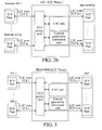
- the L2C Proxy includes a TCP proxy unit, and a control granularity conversion unit, and optionally includes a connection admission control (CAC) unit.
- a first network device connected to the L2C device (L2C Proxy) is a remote AN/local AN/aggregation node
- a second network device connected to the L2C device (L2C Proxy) is a BRAS/BNG.
- the L2C Proxy may be located at the AN/aggregation node, and L2C messages are carried on TCP connections between the first network device and the second network device.
- the TCP proxy unit is adapted to convert one received L2C message into a group of L2C messages and send the group of L2C messages, or adapted to convert a group of received L2C messages into one L2C message and send the L2C message.
- TCP connections carrying L2C messages from the remote AN/AN to the BRAS, or from the remote AN/AN to the BNG, or from the remote AN/AN to a service provider (SP) are segmented, and one TCP connection or a group of TCP connections from one side is converted into a group of TCP connections or one TCP connection to the other side after segmenting.
- the TCP proxy unit assists the AN/IP edge node (IP-EN) (including the BRAS/BNG) to perform corresponding configuration-freezing process, and optimizes the message processing according to processing results of the control granularity conversion unit and/or the CAC unit.
- IP-EN AN/IP edge node
- the control granularity conversion unit is adapted to convert a control granularity of an L2C message. For example, one L2C message taking a whole DSL physical port segment as the control granularity is converted into one L2C message or a group of L2C messages taking DSL physical port as the control granularity; or one L2C message taking a service flow as the control granularity is converted into one L2C message or a group of L2C messages taking DSL physical port as the control granularity.
- the CAC unit is adapted to perform admission control on requests about circuit configuration or multicast control of an L2C message according to a status of network resources, and inform the TCP proxy unit to establish a corresponding TCP connection between the AN and the L2C Proxy if the status of the network resources allows.
- the L2C Proxy is located at the BRAS/BNG, as shown in FIG. 3 .
- the L2C is terminated at the AN/aggregation node and a network device of the SP (for example, an ISP shown in FIG. 3 ), and the corresponding TCP peers are respectively located at the AN/aggregation node and the network device of the SP.
- FIGs. 2a , 2b, and 3 The process of the L2C method based on the L2C system shown in FIGs. 2a , 2b, and 3 is described in the following with reference to FIGs. 4 to 7 .
- the following description takes FIGs. 2a and 2b as an example, but the whole process is also applicable to the scenario shown in FIG. 3 .
- FIG. 4 is a downlink-direction flow chart 1 of an L2C method, which realizes forwarding L2C messages according to an AN based on the L2C system shown in FIGs. 2a to 2b .
- Step 401 an L2C message is sent to an L2C Proxy through a TCP connection k from a TCP communication peer BRAS/BNG, and the L2C Proxy receives the L2C message through a TCP connection port k.
- Step 402 the L2C Proxy performs a connection admission control (CAC) on requests about circuit configuration or multicast control of the L2C message according to a status of network resources; when the CAC is not passed, the L2C Proxy no longer initiates the L2C; and when the CAC is passed, the following steps are performed.
- CAC connection admission control
- Step 403 the L2C Proxy converts a control granularity of the L2C message according to a processing result of the CAC unit.
- Step 404 the L2C Proxy performs a TCP proxy function, converts one TCP connection k into another or a group of TCP connections 1...n, and forwards, through the TCP ports 1...n, the L2C message received through the TCP port k after performing the control granularity conversion.
- Step 405 the TCP communication peer AN receives the L2C message through the TCP connections 1...n, and returns TCP Acknowledgements (ACKs) 1...n.
- Step 406 after the L2C Proxy has received all the TCP ACKs 1...n of the TCP connections 1...n, the L2C Proxy returns a TCP ACK k to the TCP communication peer BRAS/BNG through the TCP connection k.
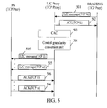
- FIG. 5 is a downlink-direction flow chart 2 of an L2C method, which realizes forwarding L2C messages according to an AN based on the L2C system shown in FIG. 3 .
- Step 501 is the same as Step 401 in FIG. 4 .
- Step 502 the L2C Proxy performs a TCP proxy function, and returns a TCP ACK k to the TCP communication peer BRAS/BNG through a TCP connection k.
- Steps 503 to 504 are the same as Steps 402 to 403 in FIG. 4 .
- Steps 505 to 506 are the same as Steps 404 to 405 in FIG. 4 .
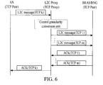
- FIG. 6 is an uplink-direction flow chart 1 of an L2C method, which realizes forwarding L2C messages according to an ISP based on the L2C system shown in FIGs. 2a to 2b .
- the uplink-direction flow chart 1 of FIG. 6 is similar to the downlink-direction flow chart 1 of FIG. 4 , and the difference lies in that no CAC process is performed in the uplink direction. Thus the uplink-direction flow chart 1 is not repeated herein.
- the number m of L2C connections between the TCP Proxy and the BRAS/BNG in the uplink direction shown in FIG. 6 is not equal to the number n of L2C connections between the TCP Proxy and the AN in the downlink direction shown in FIG.
- n ⁇ m the number of the L2C connections carried between the AN and the TCP Proxy is larger than the number m of the L2C connections carried between the BRAS/BNG and the TCP Proxy, that is to say, generally, n>m.
- FIG. 7 is an uplink-direction flow chart 2 of an L2C method, which realizes forwarding L2C messages according to an ISP based on the L2C system shown in FIG. 3 .
- the uplink-direction flow chart 2 of FIG. 7 is similar to the downlink-direction flow chart 2 of FIG. 5 , and the difference lies in that no CAC process is performed in the uplink direction. Thus the uplink-direction flow chart 2 is not repeated herein.
- the number m of the L2C connections between the TCP Proxy and the BRAS/BNG in the uplink direction shown in FIG. 7 is not equal to the number n of the L2C connections between the TCP Proxy and the AN in the downlink direction shown in FIG.
- n ⁇ m the number of the L2C connections carried between the AN and the TCP Proxy is larger than the number m of the L2C connections carried between the BRAS/BNG and the TCP Proxy, that is to say, generally, n>m.
- an L2C port configuration request message (with a control granularity in a unit of DSL physical port segment) is sent by a TCP communication peer BRAS/BNG to an L2C Proxy through a TCP connection k, and the L2C Proxy receives the message through a TCP connection port k.
- Step 802 the L2C Proxy performs a TCP proxy function, and returns a TCP ACK k to the TCP communication peer BRAS/BNG through the TCP connection k.
- Step 803 the L2C Proxy performs a CAC on the L2C port configuration request according to a status of network resources.
- the L2C Proxy no longer initiates the L2C; and when the CAC is passed, the following steps are performed, and the L2C port configuration request message with the control granularity in a unit of DSL physical port segment is converted into an L2C port configuration request message with a control granularity as DSL physical port.
- the L2C Proxy does not perform the CAC on the L2C port configuration request. Instead, the L2C Proxy directly converts the L2C port configuration request message with the control granularity in a unit of DSL physical port segment into an L2C port configuration request message with a control granularity as DSL physical port.
- Step 804 the L2C Proxy performs the TCP proxy function, converts one TCP connection k into another TCP connection j, and forwards, through a TCP port j, the L2C port configuration request message received through the TCP port k after performing the control granularity conversion.
- Step 805 a TCP communication peer AN receives the L2C message through the TCP connection j, and returns a TCP ACK j.
- Step 806 after the AN port configuration is completed, the AN returns an L2C port configuration response message (with a control granularity in a unit of DSL physical port) through a TCP connection i.
- Step 807 after the L2C Proxy receives the L2C port configuration response message, the L2C Proxy returns a TCP ACK i through the TCP connection i.
- Step 808 the L2C Proxy converts the L2C port configuration response message with the control granularity in a unit of DSL physical port into an L2C port configuration response message with a control granularity as DSL physical port segment.
- the L2C Proxy performs the CAC on the L2C port configuration request according to a status of network resources.
- the L2C Proxy no longer initiates the L2C; and when the CAC is passed, the L2C port configuration response message with the control granularity in a unit of DSL physical port segment is converted into an L2C port configuration response message with a control granularity as DSL physical port.
- Step 809 the L2C Proxy converts one TCP connection i into another TCP connection h, and forwards the L2C port configuration response message received from the TCP port i after performing the control granularity conversion to the BRAS/BNG through the TCP port h.
- the message fails to reach the BRAS/BNG within a specified period of time due to network congestion or other reasons.
- Step 810 if the L2C Proxy does not receive a TCP ACK h of the L2C port configuration response message within the specified period of time, a port configuration context is reserved, that is, a backup is made for the configured port information.
- Step 811 if the BRAS/BNG still does not receive the L2C port configuration response message within the specified period of time through a TCP retransmission mechanism, the BRAS/BNG enters a configuration-freezing state, and maintains the state before initiating the port configuration.
- Step 812 in order to exit the configuration-freezing state, the BRAS/BNG re-initiates an L2C port configuration request message (with a control granularity in a unit of DSL physical port segment), so that the TCP communication peer BRAS/BNG sends the message to the L2C Proxy through a TCP connection k, and the L2C Proxy receives the message through a TCP connection port k.
- Step 813 the L2C Proxy performs the TCP proxy function, and returns a TCP ACK k to the TCP communication peer BRAS/BNG through the TCP connection k.
- Step 814 the L2C Proxy queries the reserved port configuration context, and finds that the L2C port configuration request has been executed, so that the L2C Proxy no longer initiates operations to the AN, but directly returns an L2C port configuration response message to the BRAS/BNG through the TCP connection h.
- Step 815 the BRAS/BNG returns a TCP ACK h to the L2C Proxy through the TCP connection h.
- Step 816 the BRAS/BNG completes the port configuration and exits the configuration-freezing state.
- Step 817 the L2C Proxy receives the TCP ACK h, and removes the port configuration context.
- Steps 901 to 903 are the same as Steps 801 to 803 in FIG. 8 .
- Step 904 the L2C Proxy performs a TCP proxy function, converts one TCP connection k into another TCP connection j, and forwards the L2C port configuration request message received from the TCP port k after performing the control granularity conversion through a TCP port j.
- the L2C Proxy re-initiates an L2C port configuration request message to the AN through the TCP connection j.
- Step 905 the TCP communication peer AN receives the L2C message through the TCP connection j, and returns a TCP ACK j.
- Step 906 after the AN port configuration is completed, the AN returns an L2C port configuration response message through a TCP connection i, and the response message fails to reach the L2C Proxy within a specified period of time due to network congestion or other reasons.
- Step 907 if the AN does not receive a TCP ACK i of the L2C port configuration response message within the specified period of time, the AN enters a configuration-freezing state, and maintains the state before port configuration.
- Step 908 in order to exit the configuration-freezing state, after the specified period of time elapsed, the AN once again returns an L2C port configuration response message through the TCP connection i.
- Step 909 the L2C Proxy revives the L2C port configuration response message, and returns the TCP ACK i through the TCP connection i.
- Step 910 the AN completes the port configuration and exits the configuration-freezing state.
- one received L2C message is converted into a group of (n) L2C messages and then the group of (n) L2C messages are sent, or a group of (m) received L2C messages are converted into one L2C message and then the L2C message is sent.
- a mechanism for forwarding L2C messages according to the ISP or the AN is realized, and the traffic of L2C messages in the BNG/BRAS from access networks is reduced under a practical scenario of n ⁇ m.
- control granularity of the L2C messages can be converted freely, so as to perform operations on the whole DSL physical port segment, thereby reducing the traffic of L2C messages and performing a flexible control on the DSL physical ports according to the service flow requirement.
- the network resources may be coordinated in advance through the L2C Proxy, and when the CAC is not passed, the L2C Proxy does not initiate the L2C circuit configuration, thus avoiding a large waste of the traffic of L2C messages if the circuit configuration fails.
- the L2C may be terminated at a network device of an SP, and the L2C Proxy may be disposed in the BNG/BRAS.
- the ISPs behind the BNG/BRAS are enabled to directly control the DSL physical port segments of the AN through the L2CP.
Landscapes
- Engineering & Computer Science (AREA)
- Computer Networks & Wireless Communication (AREA)
- Signal Processing (AREA)
- Computer Security & Cryptography (AREA)
- Data Exchanges In Wide-Area Networks (AREA)
Description
- The present invention relates to the field of data communications, and more particularly to a layer 2 control (L2C) method, an L2C device, and an L2C system.
- In order to enable an access network to support new services, a controlling mechanism is required for controlling a device of the access network. For reducing the load of an operation support device in controlling each device of the access network, a layer 2 control protocol (L2CP) is adopted, which controls a large number of access nodes (ANs) through a broadband remote access server (BRAS). Recently, the L2CP is mainly adapted for topology discovery, circuit configuration, circuit test, and multicast control.
- Typically, each broadband network gateway (BNG)/BRAS supports 5000 ANs, each AN supports 30 to 40 Internet service providers (ISPs), and each ISP controls the AN through one L2C connection on the BNG/BRAS, so that each BNG/BRAS supports 5000 AN/BNG x 30 ISP/AN x 1 L2C/ISP = 150000 L2C/BNG L2C connections. Therefore, the traffic of L2C messages in the BNG/BRAS from the access networks is extremely large.
- In the conventional art, as shown in
FIG. 1 , the digital subscriber line (DSL) physical ports of the DSL access multiplexer (DSLAM) are partitioned according to service providers (SPs) (ISPs are taken as an example inFIG. 1 ). Each ISP directly controls the DSL physical ports of the corresponding DSL physical port partition through the L2CP. IETF Internet-Draft, "GSMP extensions for layer 2 control (L2C) Topology Discovery and line, configuration" describes how L2 control protocol will use TCP for exchanging GSMP protocol messages. In order to reduce the traffic of the L2C messages from the access networks, a L2C proxy, that is, an interworking function (IWF) unit inFIG. 1 , is introduced to forward the L2C messages according to the ISP or the AN (such as the DSLAM). The IWF unit is located in the Ethernet switch and the BRAS. In the conventional art, only the L2C proxy architecture is introduced, and how to realize the mechanism for forwarding the L2C messages according to the ISP or the AN still needs to be solved urgently. - Accordingly, the present invention is directed to a layer 2 control (L2C) device, an L2C method, and an L2C system, which realize a mechanism for forwarding L2C messages according to an ISP or an AN through transport control protocol (TCP) proxy.
- As a first aspect the present invention provides an L2C device, which includes a TCP proxy unit. The TCP proxy unit is adapted to segment TCP connections carrying L2C messages between network devices that are connected to the L2C device, convert one TCP connection from one side into n TCP connections after segmenting, and send the n TCP connections to a network device connected to the L2C device on the other side; or convert m TCP connections from one side into one TCP connection after segmenting, and then send the TCP connection to the network device connected to the L2C device on the other side.
- As a second aspect the present invention provides an L2C method, which includes the following steps.
- In Step A1, a TCP connection sent from a network device on one side through a TCP connection carrying L2C messages is received.
- In Step B1, the TCP connection is converted into n TCP connections, and the converted TCP connections are sent to a network device on the other side.
- Alternatively, in Step A2, m TCP connections sent from a network device on one side through a TCP connection carrying L2C messages are received.
- In Step B2, the TCP connections are converted into one TCP connection, and the converted TCP connection is sent to a network device on the other side.
- As a third aspect the present invention provides an L2C system, which includes an L2C device including a TCP proxy unit. The TCP proxy unit is adapted to segment TCP connections carrying L2C messages between network devices connected to the L2C device, convert one TCP connection from one side into n TCP connections after segmenting, and send the n TCP connections to a network device connected to the L2C device on the other side; or convert m TCP connections from one side into one TCP connection after segmenting, and send the TCP connection to the network device connected to the L2C device on the other side.
- As seen from the technical solutions provided by the present invention, by using TCP proxy, TCP connections carrying L2C messages between network devices connected to the TCP proxy are segmented. One TCP connection from one side is converted into a group of (n) TCP connections after segmenting, and the group of (n) TCP connections is sent to a network device connected to the device on the other side. Alternatively, a group of (m) received TCP connections are converted into one TCP connection, and the TCP connection is sent to the network device connected to the device on the other side. Therefore, a mechanism for forwarding L2C messages according to the ISP or the AN is realized, thereby reducing a traffic of the L2C messages in the BNG/BRAS from access networks.
-
-
FIG. 1 is a schematic view of an L2C proxy system in the conventional art; -
FIG. 2a is a functional block diagram 1 of an L2C proxy system terminated at remote ANs according to an embodiment of the present invention; -
FIG. 2b is a functional block diagram 1 of an L2C proxy system terminated at local ANs according to an embodiment of the present invention; -
FIG. 3 is a functional block diagram 2 of an L2C proxy system according to an embodiment of the present invention; -
FIG. 4 is a downlink-direction flow chart 1 of an L2C proxy method according to an embodiment of the present invention; -
FIG. 5 is a downlink-direction flow chart 2 of an L2C proxy method according to an embodiment of the present invention; -
FIG. 6 is an uplink-direction flow chart 1 of an L2C proxy method according to an embodiment of the present invention; -
FIG. 7 is an uplink-direction flow chart 2 of an L2C proxy method according to an embodiment of the present invention; -
FIG. 8 is aflow chart 1 of configuring L2C ports according to an embodiment of the present invention (when a failure occurs between an L2C Proxy and a BRAS/BNG); and -
FIG. 9 is aflow chart 1 of configuring L2C ports (when a failure occurs between an L2C Proxy and an AN). - In order to further illustrate the technical solutions of an L2C method, an L2C device, and an L2C system provided in the present invention, specific embodiments are described in the following through accompanying drawings by taking, for example, an L2C Proxy to serve as an L2C device.
- In an embodiment of the present invention, the L2C Proxy includes a TCP proxy unit, and a control granularity conversion unit, and optionally includes a connection admission control (CAC) unit. Referring to
FIGs. 2a and2b , a first network device connected to the L2C device (L2C Proxy) is a remote AN/local AN/aggregation node, and a second network device connected to the L2C device (L2C Proxy) is a BRAS/BNG. The L2C Proxy may be located at the AN/aggregation node, and L2C messages are carried on TCP connections between the first network device and the second network device. - The TCP proxy unit is adapted to convert one received L2C message into a group of L2C messages and send the group of L2C messages, or adapted to convert a group of received L2C messages into one L2C message and send the L2C message. Particularly, TCP connections carrying L2C messages from the remote AN/AN to the BRAS, or from the remote AN/AN to the BNG, or from the remote AN/AN to a service provider (SP) are segmented, and one TCP connection or a group of TCP connections from one side is converted into a group of TCP connections or one TCP connection to the other side after segmenting. If an L2C message is lost, the TCP proxy unit assists the AN/IP edge node (IP-EN) (including the BRAS/BNG) to perform corresponding configuration-freezing process, and optimizes the message processing according to processing results of the control granularity conversion unit and/or the CAC unit.
- The control granularity conversion unit is adapted to convert a control granularity of an L2C message. For example, one L2C message taking a whole DSL physical port segment as the control granularity is converted into one L2C message or a group of L2C messages taking DSL physical port as the control granularity; or one L2C message taking a service flow as the control granularity is converted into one L2C message or a group of L2C messages taking DSL physical port as the control granularity.
- The CAC unit is adapted to perform admission control on requests about circuit configuration or multicast control of an L2C message according to a status of network resources, and inform the TCP proxy unit to establish a corresponding TCP connection between the AN and the L2C Proxy if the status of the network resources allows.
- In another embodiment of the present invention, the L2C Proxy is located at the BRAS/BNG, as shown in
FIG. 3 . The L2C is terminated at the AN/aggregation node and a network device of the SP (for example, an ISP shown inFIG. 3 ), and the corresponding TCP peers are respectively located at the AN/aggregation node and the network device of the SP. - The process of the L2C method based on the L2C system shown in
FIGs. 2a ,2b, and 3 is described in the following with reference toFIGs. 4 to 7 . The following description takesFIGs. 2a and2b as an example, but the whole process is also applicable to the scenario shown inFIG. 3 . -
FIG. 4 is a downlink-direction flow chart 1 of an L2C method, which realizes forwarding L2C messages according to an AN based on the L2C system shown inFIGs. 2a to 2b . - In
Step 401, an L2C message is sent to an L2C Proxy through a TCP connection k from a TCP communication peer BRAS/BNG, and the L2C Proxy receives the L2C message through a TCP connection port k. - In
Step 402, the L2C Proxy performs a connection admission control (CAC) on requests about circuit configuration or multicast control of the L2C message according to a status of network resources; when the CAC is not passed, the L2C Proxy no longer initiates the L2C; and when the CAC is passed, the following steps are performed. - In
Step 403, the L2C Proxy converts a control granularity of the L2C message according to a processing result of the CAC unit. - In
Step 404, the L2C Proxy performs a TCP proxy function, converts one TCP connection k into another or a group ofTCP connections 1...n, and forwards, through theTCP ports 1...n, the L2C message received through the TCP port k after performing the control granularity conversion. - In
Step 405, the TCP communication peer AN receives the L2C message through theTCP connections 1...n, and returns TCP Acknowledgements (ACKs) 1...n. - In
Step 406, after the L2C Proxy has received all theTCP ACKs 1...n of theTCP connections 1...n, the L2C Proxy returns a TCP ACK k to the TCP communication peer BRAS/BNG through the TCP connection k. -
FIG. 5 is a downlink-direction flow chart 2 of an L2C method, which realizes forwarding L2C messages according to an AN based on the L2C system shown inFIG. 3 . - Step 501 is the same as
Step 401 inFIG. 4 . - In
Step 502, the L2C Proxy performs a TCP proxy function, and returns a TCP ACK k to the TCP communication peer BRAS/BNG through a TCP connection k. -
Steps 503 to 504 are the same asSteps 402 to 403 inFIG. 4 . -
Steps 505 to 506 are the same asSteps 404 to 405 inFIG. 4 . -
FIG. 6 is an uplink-direction flow chart 1 of an L2C method, which realizes forwarding L2C messages according to an ISP based on the L2C system shown inFIGs. 2a to 2b . The uplink-direction flow chart 1 ofFIG. 6 is similar to the downlink-direction flow chart 1 ofFIG. 4 , and the difference lies in that no CAC process is performed in the uplink direction. Thus the uplink-direction flow chart 1 is not repeated herein. In addition, the number m of L2C connections between the TCP Proxy and the BRAS/BNG in the uplink direction shown inFIG. 6 is not equal to the number n of L2C connections between the TCP Proxy and the AN in the downlink direction shown inFIG. 4 , that is, n≠m, and n and m are both positive integers. In practice, the number n of the L2C connections carried between the AN and the TCP Proxy is larger than the number m of the L2C connections carried between the BRAS/BNG and the TCP Proxy, that is to say, generally, n>m. -
FIG. 7 is an uplink-direction flow chart 2 of an L2C method, which realizes forwarding L2C messages according to an ISP based on the L2C system shown inFIG. 3 . The uplink-direction flow chart 2 ofFIG. 7 is similar to the downlink-direction flow chart 2 ofFIG. 5 , and the difference lies in that no CAC process is performed in the uplink direction. Thus the uplink-direction flow chart 2 is not repeated herein. In addition, the number m of the L2C connections between the TCP Proxy and the BRAS/BNG in the uplink direction shown inFIG. 7 is not equal to the number n of the L2C connections between the TCP Proxy and the AN in the downlink direction shown inFIG. 5 , that is, n≠m, and n and m are both positive integers. In practice, the number n of the L2C connections carried between the AN and the TCP Proxy is larger than the number m of the L2C connections carried between the BRAS/BNG and the TCP Proxy, that is to say, generally, n>m. - In order to further illustrate the technical solution according to the embodiment of the present invention, referring to
FIG. 8 , the process of an L2C method is further described in detail, by taking L2C port configuration as an example, in a scenario where a failure occurs between an L2C Proxy and a BRAS/BNG. - In
Step 801, an L2C port configuration request message (with a control granularity in a unit of DSL physical port segment) is sent by a TCP communication peer BRAS/BNG to an L2C Proxy through a TCP connection k, and the L2C Proxy receives the message through a TCP connection port k. - In
Step 802, the L2C Proxy performs a TCP proxy function, and returns a TCP ACK k to the TCP communication peer BRAS/BNG through the TCP connection k. - In
Step 803, the L2C Proxy performs a CAC on the L2C port configuration request according to a status of network resources. When the CAC is not passed, the L2C Proxy no longer initiates the L2C; and when the CAC is passed, the following steps are performed, and the L2C port configuration request message with the control granularity in a unit of DSL physical port segment is converted into an L2C port configuration request message with a control granularity as DSL physical port. - Alternatively, the L2C Proxy does not perform the CAC on the L2C port configuration request. Instead, the L2C Proxy directly converts the L2C port configuration request message with the control granularity in a unit of DSL physical port segment into an L2C port configuration request message with a control granularity as DSL physical port.
- In
Step 804, the L2C Proxy performs the TCP proxy function, converts one TCP connection k into another TCP connection j, and forwards, through a TCP port j, the L2C port configuration request message received through the TCP port k after performing the control granularity conversion. - In
Step 805, a TCP communication peer AN receives the L2C message through the TCP connection j, and returns a TCP ACK j. - In
Step 806, after the AN port configuration is completed, the AN returns an L2C port configuration response message (with a control granularity in a unit of DSL physical port) through a TCP connection i. - In
Step 807, after the L2C Proxy receives the L2C port configuration response message, the L2C Proxy returns a TCP ACK i through the TCP connection i. - In
Step 808, the L2C Proxy converts the L2C port configuration response message with the control granularity in a unit of DSL physical port into an L2C port configuration response message with a control granularity as DSL physical port segment. - Alternatively, the L2C Proxy performs the CAC on the L2C port configuration request according to a status of network resources. When the CAC is not passed, the L2C Proxy no longer initiates the L2C; and when the CAC is passed, the L2C port configuration response message with the control granularity in a unit of DSL physical port segment is converted into an L2C port configuration response message with a control granularity as DSL physical port.
- In
Step 809, the L2C Proxy converts one TCP connection i into another TCP connection h, and forwards the L2C port configuration response message received from the TCP port i after performing the control granularity conversion to the BRAS/BNG through the TCP port h. - The message fails to reach the BRAS/BNG within a specified period of time due to network congestion or other reasons.
- In
Step 810, if the L2C Proxy does not receive a TCP ACK h of the L2C port configuration response message within the specified period of time, a port configuration context is reserved, that is, a backup is made for the configured port information. - In
Step 811, if the BRAS/BNG still does not receive the L2C port configuration response message within the specified period of time through a TCP retransmission mechanism, the BRAS/BNG enters a configuration-freezing state, and maintains the state before initiating the port configuration. - In
Step 812, in order to exit the configuration-freezing state, the BRAS/BNG re-initiates an L2C port configuration request message (with a control granularity in a unit of DSL physical port segment), so that the TCP communication peer BRAS/BNG sends the message to the L2C Proxy through a TCP connection k, and the L2C Proxy receives the message through a TCP connection port k. - In
Step 813, the L2C Proxy performs the TCP proxy function, and returns a TCP ACK k to the TCP communication peer BRAS/BNG through the TCP connection k. - In
Step 814, the L2C Proxy queries the reserved port configuration context, and finds that the L2C port configuration request has been executed, so that the L2C Proxy no longer initiates operations to the AN, but directly returns an L2C port configuration response message to the BRAS/BNG through the TCP connection h. - In
Step 815, the BRAS/BNG returns a TCP ACK h to the L2C Proxy through the TCP connection h. - In
Step 816, the BRAS/BNG completes the port configuration and exits the configuration-freezing state. - In
Step 817, the L2C Proxy receives the TCP ACK h, and removes the port configuration context. - Referring to
FIG. 9 , the process of an L2C method is further illustrated in the situation that a failure occurs between the L2C Proxy and the AN by taking an L2C port configuration as an example. -
Steps 901 to 903 are the same asSteps 801 to 803 inFIG. 8 . - In
Step 904, the L2C Proxy performs a TCP proxy function, converts one TCP connection k into another TCP connection j, and forwards the L2C port configuration request message received from the TCP port k after performing the control granularity conversion through a TCP port j. - If the message fails to reach the AN within a specified period of time due to network congestion or other reasons, after the specified period of time elapsed, the L2C Proxy re-initiates an L2C port configuration request message to the AN through the TCP connection j.
- In
Step 905, the TCP communication peer AN receives the L2C message through the TCP connection j, and returns a TCP ACK j. - In
Step 906, after the AN port configuration is completed, the AN returns an L2C port configuration response message through a TCP connection i, and the response message fails to reach the L2C Proxy within a specified period of time due to network congestion or other reasons. - In
Step 907, if the AN does not receive a TCP ACK i of the L2C port configuration response message within the specified period of time, the AN enters a configuration-freezing state, and maintains the state before port configuration. - In
Step 908, in order to exit the configuration-freezing state, after the specified period of time elapsed, the AN once again returns an L2C port configuration response message through the TCP connection i. - In
Step 909, the L2C Proxy revives the L2C port configuration response message, and returns the TCP ACK i through the TCP connection i. - In
Step 910, the AN completes the port configuration and exits the configuration-freezing state. - As seen from the technical solutions provided in the embodiments, by using the TCP proxy implementation method according to the embodiments of the present invention, one received L2C message is converted into a group of (n) L2C messages and then the group of (n) L2C messages are sent, or a group of (m) received L2C messages are converted into one L2C message and then the L2C message is sent. In this way, a mechanism for forwarding L2C messages according to the ISP or the AN is realized, and the traffic of L2C messages in the BNG/BRAS from access networks is reduced under a practical scenario of n≠m.
- Furthermore, the control granularity of the L2C messages can be converted freely, so as to perform operations on the whole DSL physical port segment, thereby reducing the traffic of L2C messages and performing a flexible control on the DSL physical ports according to the service flow requirement.
- Meanwhile, by using the CAC mechanism for L2C circuit configuration, the network resources may be coordinated in advance through the L2C Proxy, and when the CAC is not passed, the L2C Proxy does not initiate the L2C circuit configuration, thus avoiding a large waste of the traffic of L2C messages if the circuit configuration fails.
- Moreover, in the embodiments of the present invention, the L2C may be terminated at a network device of an SP, and the L2C Proxy may be disposed in the BNG/BRAS. Thus, in a wholesale scenario, the ISPs behind the BNG/BRAS are enabled to directly control the DSL physical port segments of the AN through the L2CP.
- The above descriptions are merely preferred embodiments of the present invention, but not intended to limit the present invention.
Claims (14)
- A layer 2 control, L2C, device for forwarding L2C messages in access networks, comprising:a transport control protocol, TCP, proxy unit, adapted to segment TCP connections carrying L2C messages between network devices connected to the L2C device either by, converting one TCP connection received on one side into n TCP connections after segmenting and sending the n TCP connections to a network device connected to the device on the other side; or by converting m TCP connections received on one side into one TCP connection and sending the one TCP connection to the network device connected to the device on the other side.
- The device according to claim 1, further comprising:a control granularity conversion unit, connected to the TCP proxy unit, and adapted to perform a conversion on control granularities of L2C messages.
- The device according to claim 1, further comprising:a connection admission control, CAC, unit, connected to the TCP proxy unit, and adapted to perform an admission control on requests of the L2C messages for network resources according to a status of network resources.
- The device according to claim 1, wherein the TCP proxy unit further comprises a storage module, adapted to reserve L2C configuration context when no response message for an L2C port configuration response message sent by the TCP proxy unit is received within a specified period of time;
and adapted to delete the reserved L2C configuration context when the response message for the L2C port configuration response message sent by the TCP proxy unit is received. - The device according to claim 3, wherein the L2C messages comprise circuit configuration messages or multicast control messages.
- The device according to claim 1 or 4, wherein the L2C device is an access node, AN, a broadband remote access server, BRAS, or a broadband network gateway, BNG, or the L2C device is configured as a component on the AN, the BRAS, or the BNG.
- A layer 2 control, L2C, system, comprising the device according to any one of claims I to 6.
- A layer 2 control, L2C, method for forwarding L2C messages in access networks, comprising:Step A1, receiving a TCP connection sent from a network device on one side through a TCP connection carrying L2C messages; andStep B1, converting the TCP connection into n TCP connections, and sending the converted TCP connections to a network device on the other side; orStep A2, receiving m TCP connections sent from a network device on one side through a TCP connection carrying L2C messages; andStep B2, converting the TCP connections into one TCP connection, and sending the converted TCP connection to a network device on the other side.
- The method according to claim 8, further comprising:after receiving an L2C message sent from the network device on one side through the TCP connection carrying L2C messages, returning a TCP Acknowledgement, ACK, to the network device through the TCP connection.
- The method according to claim 8 or 9, further comprising:after receiving a TCP response message sent from the network device on the other side, forwarding the TCP response message to a peer network device through the TCP connection mentioned in Step A1 or A2.
- The method according to claim 8, further comprising: converting a control granularity of the L2C message before Step B 1 or B2.
- The method according to claim 8, further comprising: performing an admission control on a TCP connection request of the L2C message according to a status of network resources before Step B 1 or B2.
- The method according to claim 8, further comprising:reserving an L2C configuration context when no response message from the network device on the other side is received within a specified period of time after the L2C message is sent to the network device on the other side through a converted TCP connection;returning a response message to the network device on the other side when receiving an L2C port configuration request message, and deleting the reserved L2C configuration context.
- The method according to claim 12, wherein the TCP connection carrying L2C messages between the network devices further comprises:a TCP connection carrying L2C messages between a remote access node, AN/local AN/aggregation node and a broadband remote access server, BRAS;a TCP connection carrying L2C messages between a remote AN/local AN/aggregation node and a broadband network gateway, BNG; ora TCP connection carrying L2C messages between a remote AN/local AN/aggregation node and a remote AN/local AN/aggregation node of a service provider, SP.
Priority Applications (1)
| Application Number | Priority Date | Filing Date | Title |
|---|---|---|---|
| EP12194157.9A EP2566131B1 (en) | 2007-05-15 | 2008-05-15 | A L2C method, device and system |
Applications Claiming Priority (2)
| Application Number | Priority Date | Filing Date | Title |
|---|---|---|---|
| CN200710074462A CN101309285B (en) | 2007-05-15 | 2007-05-15 | Second layer control method,apparatus and system thereof |
| PCT/CN2008/070978 WO2008138275A1 (en) | 2007-05-15 | 2008-05-15 | A l2c method, device and system |
Related Child Applications (1)
| Application Number | Title | Priority Date | Filing Date |
|---|---|---|---|
| EP12194157.9A Division EP2566131B1 (en) | 2007-05-15 | 2008-05-15 | A L2C method, device and system |
Publications (3)
| Publication Number | Publication Date |
|---|---|
| EP2139188A1 EP2139188A1 (en) | 2009-12-30 |
| EP2139188A4 EP2139188A4 (en) | 2010-12-29 |
| EP2139188B1 true EP2139188B1 (en) | 2012-12-12 |
Family
ID=40001710
Family Applications (2)
| Application Number | Title | Priority Date | Filing Date |
|---|---|---|---|
| EP08748584A Active EP2139188B1 (en) | 2007-05-15 | 2008-05-15 | A l2c method, device and system |
| EP12194157.9A Active EP2566131B1 (en) | 2007-05-15 | 2008-05-15 | A L2C method, device and system |
Family Applications After (1)
| Application Number | Title | Priority Date | Filing Date |
|---|---|---|---|
| EP12194157.9A Active EP2566131B1 (en) | 2007-05-15 | 2008-05-15 | A L2C method, device and system |
Country Status (4)
| Country | Link |
|---|---|
| EP (2) | EP2139188B1 (en) |
| CN (1) | CN101309285B (en) |
| ES (1) | ES2399941T3 (en) |
| WO (1) | WO2008138275A1 (en) |
Family Cites Families (6)
| Publication number | Priority date | Publication date | Assignee | Title |
|---|---|---|---|---|
| US7289509B2 (en) * | 2002-02-14 | 2007-10-30 | International Business Machines Corporation | Apparatus and method of splitting a data stream over multiple transport control protocol/internet protocol (TCP/IP) connections |
| KR20040091731A (en) * | 2002-03-14 | 2004-10-28 | 코닌클리케 필립스 일렉트로닉스 엔.브이. | Method of and system for multi-path communication |
| US20040015591A1 (en) * | 2002-07-18 | 2004-01-22 | Wang Frank Xiao-Dong | Collective TCP control for improved wireless network performance |
| CN100589484C (en) * | 2005-11-29 | 2010-02-10 | 华为技术有限公司 | Bearer system and method of media gateway control protocol |
| EP1793553A1 (en) * | 2005-12-02 | 2007-06-06 | Alcatel Lucent | A transmission control protocol (TCP) host with TCP convergence module |
| CN100423513C (en) * | 2006-03-21 | 2008-10-01 | 杭州华三通信技术有限公司 | A Merging Method of TCP Connection |
-
2007
- 2007-05-15 CN CN200710074462A patent/CN101309285B/en active Active
-
2008
- 2008-05-15 EP EP08748584A patent/EP2139188B1/en active Active
- 2008-05-15 WO PCT/CN2008/070978 patent/WO2008138275A1/en not_active Ceased
- 2008-05-15 ES ES08748584T patent/ES2399941T3/en active Active
- 2008-05-15 EP EP12194157.9A patent/EP2566131B1/en active Active
Also Published As
| Publication number | Publication date |
|---|---|
| CN101309285B (en) | 2012-09-05 |
| ES2399941T3 (en) | 2013-04-04 |
| CN101309285A (en) | 2008-11-19 |
| WO2008138275A1 (en) | 2008-11-20 |
| EP2566131A1 (en) | 2013-03-06 |
| EP2139188A1 (en) | 2009-12-30 |
| EP2139188A4 (en) | 2010-12-29 |
| EP2566131B1 (en) | 2020-02-05 |
Similar Documents
| Publication | Publication Date | Title |
|---|---|---|
| EP2747355B1 (en) | Aggregation network with centralized control | |
| US7568040B2 (en) | Techniques for establishing subscriber sessions on an access network using DHCP | |
| US11621907B2 (en) | Enhanced two-way active measurement protocol | |
| CN103069783B (en) | Staggered Hierarchical Optimization Protocol | |
| CN102084638B (en) | Deterministic session load-balancing and redundancy of access servers in a computer network | |
| US7366894B1 (en) | Method and apparatus for dynamically securing voice and other delay-sensitive network traffic | |
| CN102315961B (en) | Execute Path-Oriented System Administration | |
| KR102050910B1 (en) | Method and system to enable re-routing for home networks upon connectivity failure | |
| WO2009071030A1 (en) | Method for reporting device information, system and device for obtaining device information | |
| JP2009500979A (en) | Transparent transport of Fiber Channel traffic over packet-switched networks | |
| EP1693996B1 (en) | Automatic discovery of psuedo-wire peer addresses in ethernet-based networks | |
| EP1727309A1 (en) | Methods and apparatus for monitoring link integrity for signaling traffic over a path traversing hybrid ATM/ethernet infrastructure in support of packet voice service provisioning | |
| CN113055293A (en) | Routing method and device in software defined wide area network and communication system | |
| CN103188153B (en) | BFD file transmitting method and equipment on a kind of broadcasting network link | |
| EP4373051A1 (en) | Apparatuses, methods and non-transitory computer-readable storage mediums for network access to residential gateways | |
| CN101132327A (en) | IP telecommunication network system integrated service data transmission method | |
| EP2139188B1 (en) | A l2c method, device and system | |
| CN116436729A (en) | Message transmission method, networking system and access cloud gateway | |
| EP4354919B1 (en) | Multicast local breakout for customer premise equipment in a 5g wireless wireline convergence at an access gateway function | |
| US12556471B2 (en) | Route cost based on route metrics and path type preference | |
| EP4546747A1 (en) | Apparatuses, methods and non-transitory computer-readable storage mediums for network access | |
| JP2004032453A (en) | Packet communication system, packet transfer device and packet transfer control program used in the system | |
| US20090052446A1 (en) | Communications Interface | |
| JP2001119427A (en) | Message communication method and its system |
Legal Events
| Date | Code | Title | Description |
|---|---|---|---|
| PUAI | Public reference made under article 153(3) epc to a published international application that has entered the european phase |
Free format text: ORIGINAL CODE: 0009012 |
|
| 17P | Request for examination filed |
Effective date: 20091111 |
|
| AK | Designated contracting states |
Kind code of ref document: A1 Designated state(s): AT BE BG CH CY CZ DE DK EE ES FI FR GB GR HR HU IE IS IT LI LT LU LV MC MT NL NO PL PT RO SE SI SK TR |
|
| DAX | Request for extension of the european patent (deleted) | ||
| A4 | Supplementary search report drawn up and despatched |
Effective date: 20101125 |
|
| GRAP | Despatch of communication of intention to grant a patent |
Free format text: ORIGINAL CODE: EPIDOSNIGR1 |
|
| GRAS | Grant fee paid |
Free format text: ORIGINAL CODE: EPIDOSNIGR3 |
|
| GRAA | (expected) grant |
Free format text: ORIGINAL CODE: 0009210 |
|
| AK | Designated contracting states |
Kind code of ref document: B1 Designated state(s): AT BE BG CH CY CZ DE DK EE ES FI FR GB GR HR HU IE IS IT LI LT LU LV MC MT NL NO PL PT RO SE SI SK TR |
|
| REG | Reference to a national code |
Ref country code: GB Ref legal event code: FG4D |
|
| REG | Reference to a national code |
Ref country code: CH Ref legal event code: EP |
|
| REG | Reference to a national code |
Ref country code: AT Ref legal event code: REF Ref document number: 588804 Country of ref document: AT Kind code of ref document: T Effective date: 20121215 |
|
| REG | Reference to a national code |
Ref country code: IE Ref legal event code: FG4D |
|
| REG | Reference to a national code |
Ref country code: DE Ref legal event code: R096 Ref document number: 602008020792 Country of ref document: DE Effective date: 20130207 |
|
| REG | Reference to a national code |
Ref country code: ES Ref legal event code: FG2A Ref document number: 2399941 Country of ref document: ES Kind code of ref document: T3 Effective date: 20130404 |
|
| PG25 | Lapsed in a contracting state [announced via postgrant information from national office to epo] |
Ref country code: NO Free format text: LAPSE BECAUSE OF FAILURE TO SUBMIT A TRANSLATION OF THE DESCRIPTION OR TO PAY THE FEE WITHIN THE PRESCRIBED TIME-LIMIT Effective date: 20130312 Ref country code: HR Free format text: LAPSE BECAUSE OF FAILURE TO SUBMIT A TRANSLATION OF THE DESCRIPTION OR TO PAY THE FEE WITHIN THE PRESCRIBED TIME-LIMIT Effective date: 20121212 Ref country code: LT Free format text: LAPSE BECAUSE OF FAILURE TO SUBMIT A TRANSLATION OF THE DESCRIPTION OR TO PAY THE FEE WITHIN THE PRESCRIBED TIME-LIMIT Effective date: 20121212 Ref country code: FI Free format text: LAPSE BECAUSE OF FAILURE TO SUBMIT A TRANSLATION OF THE DESCRIPTION OR TO PAY THE FEE WITHIN THE PRESCRIBED TIME-LIMIT Effective date: 20121212 Ref country code: SE Free format text: LAPSE BECAUSE OF FAILURE TO SUBMIT A TRANSLATION OF THE DESCRIPTION OR TO PAY THE FEE WITHIN THE PRESCRIBED TIME-LIMIT Effective date: 20121212 |
|
| REG | Reference to a national code |
Ref country code: NL Ref legal event code: VDEP Effective date: 20121212 |
|
| REG | Reference to a national code |
Ref country code: AT Ref legal event code: MK05 Ref document number: 588804 Country of ref document: AT Kind code of ref document: T Effective date: 20121212 |
|
| REG | Reference to a national code |
Ref country code: LT Ref legal event code: MG4D |
|
| PG25 | Lapsed in a contracting state [announced via postgrant information from national office to epo] |
Ref country code: GR Free format text: LAPSE BECAUSE OF FAILURE TO SUBMIT A TRANSLATION OF THE DESCRIPTION OR TO PAY THE FEE WITHIN THE PRESCRIBED TIME-LIMIT Effective date: 20130313 Ref country code: SI Free format text: LAPSE BECAUSE OF FAILURE TO SUBMIT A TRANSLATION OF THE DESCRIPTION OR TO PAY THE FEE WITHIN THE PRESCRIBED TIME-LIMIT Effective date: 20121212 Ref country code: LV Free format text: LAPSE BECAUSE OF FAILURE TO SUBMIT A TRANSLATION OF THE DESCRIPTION OR TO PAY THE FEE WITHIN THE PRESCRIBED TIME-LIMIT Effective date: 20121212 |
|
| PG25 | Lapsed in a contracting state [announced via postgrant information from national office to epo] |
Ref country code: IS Free format text: LAPSE BECAUSE OF FAILURE TO SUBMIT A TRANSLATION OF THE DESCRIPTION OR TO PAY THE FEE WITHIN THE PRESCRIBED TIME-LIMIT Effective date: 20130412 Ref country code: EE Free format text: LAPSE BECAUSE OF FAILURE TO SUBMIT A TRANSLATION OF THE DESCRIPTION OR TO PAY THE FEE WITHIN THE PRESCRIBED TIME-LIMIT Effective date: 20121212 Ref country code: AT Free format text: LAPSE BECAUSE OF FAILURE TO SUBMIT A TRANSLATION OF THE DESCRIPTION OR TO PAY THE FEE WITHIN THE PRESCRIBED TIME-LIMIT Effective date: 20121212 Ref country code: BG Free format text: LAPSE BECAUSE OF FAILURE TO SUBMIT A TRANSLATION OF THE DESCRIPTION OR TO PAY THE FEE WITHIN THE PRESCRIBED TIME-LIMIT Effective date: 20130312 Ref country code: SK Free format text: LAPSE BECAUSE OF FAILURE TO SUBMIT A TRANSLATION OF THE DESCRIPTION OR TO PAY THE FEE WITHIN THE PRESCRIBED TIME-LIMIT Effective date: 20121212 Ref country code: CZ Free format text: LAPSE BECAUSE OF FAILURE TO SUBMIT A TRANSLATION OF THE DESCRIPTION OR TO PAY THE FEE WITHIN THE PRESCRIBED TIME-LIMIT Effective date: 20121212 |
|
| PG25 | Lapsed in a contracting state [announced via postgrant information from national office to epo] |
Ref country code: PT Free format text: LAPSE BECAUSE OF FAILURE TO SUBMIT A TRANSLATION OF THE DESCRIPTION OR TO PAY THE FEE WITHIN THE PRESCRIBED TIME-LIMIT Effective date: 20130412 Ref country code: NL Free format text: LAPSE BECAUSE OF FAILURE TO SUBMIT A TRANSLATION OF THE DESCRIPTION OR TO PAY THE FEE WITHIN THE PRESCRIBED TIME-LIMIT Effective date: 20121212 Ref country code: PL Free format text: LAPSE BECAUSE OF FAILURE TO SUBMIT A TRANSLATION OF THE DESCRIPTION OR TO PAY THE FEE WITHIN THE PRESCRIBED TIME-LIMIT Effective date: 20121212 Ref country code: RO Free format text: LAPSE BECAUSE OF FAILURE TO SUBMIT A TRANSLATION OF THE DESCRIPTION OR TO PAY THE FEE WITHIN THE PRESCRIBED TIME-LIMIT Effective date: 20121212 |
|
| PLBE | No opposition filed within time limit |
Free format text: ORIGINAL CODE: 0009261 |
|
| STAA | Information on the status of an ep patent application or granted ep patent |
Free format text: STATUS: NO OPPOSITION FILED WITHIN TIME LIMIT |
|
| PG25 | Lapsed in a contracting state [announced via postgrant information from national office to epo] |
Ref country code: DK Free format text: LAPSE BECAUSE OF FAILURE TO SUBMIT A TRANSLATION OF THE DESCRIPTION OR TO PAY THE FEE WITHIN THE PRESCRIBED TIME-LIMIT Effective date: 20121212 |
|
| 26N | No opposition filed |
Effective date: 20130913 |
|
| PG25 | Lapsed in a contracting state [announced via postgrant information from national office to epo] |
Ref country code: CY Free format text: LAPSE BECAUSE OF FAILURE TO SUBMIT A TRANSLATION OF THE DESCRIPTION OR TO PAY THE FEE WITHIN THE PRESCRIBED TIME-LIMIT Effective date: 20121212 |
|
| PG25 | Lapsed in a contracting state [announced via postgrant information from national office to epo] |
Ref country code: MC Free format text: LAPSE BECAUSE OF FAILURE TO SUBMIT A TRANSLATION OF THE DESCRIPTION OR TO PAY THE FEE WITHIN THE PRESCRIBED TIME-LIMIT Effective date: 20121212 |
|
| REG | Reference to a national code |
Ref country code: CH Ref legal event code: PL |
|
| REG | Reference to a national code |
Ref country code: DE Ref legal event code: R097 Ref document number: 602008020792 Country of ref document: DE Effective date: 20130913 |
|
| PG25 | Lapsed in a contracting state [announced via postgrant information from national office to epo] |
Ref country code: LI Free format text: LAPSE BECAUSE OF NON-PAYMENT OF DUE FEES Effective date: 20130531 Ref country code: CH Free format text: LAPSE BECAUSE OF NON-PAYMENT OF DUE FEES Effective date: 20130531 |
|
| REG | Reference to a national code |
Ref country code: IE Ref legal event code: MM4A |
|
| PG25 | Lapsed in a contracting state [announced via postgrant information from national office to epo] |
Ref country code: IE Free format text: LAPSE BECAUSE OF NON-PAYMENT OF DUE FEES Effective date: 20130515 |
|
| PG25 | Lapsed in a contracting state [announced via postgrant information from national office to epo] |
Ref country code: MT Free format text: LAPSE BECAUSE OF FAILURE TO SUBMIT A TRANSLATION OF THE DESCRIPTION OR TO PAY THE FEE WITHIN THE PRESCRIBED TIME-LIMIT Effective date: 20121212 |
|
| PG25 | Lapsed in a contracting state [announced via postgrant information from national office to epo] |
Ref country code: TR Free format text: LAPSE BECAUSE OF FAILURE TO SUBMIT A TRANSLATION OF THE DESCRIPTION OR TO PAY THE FEE WITHIN THE PRESCRIBED TIME-LIMIT Effective date: 20121212 |
|
| PG25 | Lapsed in a contracting state [announced via postgrant information from national office to epo] |
Ref country code: LU Free format text: LAPSE BECAUSE OF NON-PAYMENT OF DUE FEES Effective date: 20130515 Ref country code: HU Free format text: LAPSE BECAUSE OF FAILURE TO SUBMIT A TRANSLATION OF THE DESCRIPTION OR TO PAY THE FEE WITHIN THE PRESCRIBED TIME-LIMIT; INVALID AB INITIO Effective date: 20080515 |
|
| REG | Reference to a national code |
Ref country code: FR Ref legal event code: PLFP Year of fee payment: 9 |
|
| REG | Reference to a national code |
Ref country code: FR Ref legal event code: PLFP Year of fee payment: 10 |
|
| REG | Reference to a national code |
Ref country code: FR Ref legal event code: PLFP Year of fee payment: 11 |
|
| REG | Reference to a national code |
Ref country code: DE Ref legal event code: R079 Ref document number: 602008020792 Country of ref document: DE Free format text: PREVIOUS MAIN CLASS: H04L0029060000 Ipc: H04L0065000000 |
|
| REG | Reference to a national code |
Ref country code: FR Ref legal event code: PLFP Year of fee payment: 16 |
|
| PGFP | Annual fee paid to national office [announced via postgrant information from national office to epo] |
Ref country code: DE Payment date: 20250402 Year of fee payment: 18 |
|
| PGFP | Annual fee paid to national office [announced via postgrant information from national office to epo] |
Ref country code: GB Payment date: 20250401 Year of fee payment: 18 Ref country code: ES Payment date: 20250603 Year of fee payment: 18 |
|
| PGFP | Annual fee paid to national office [announced via postgrant information from national office to epo] |
Ref country code: BE Payment date: 20250410 Year of fee payment: 18 Ref country code: IT Payment date: 20250422 Year of fee payment: 18 |
|
| PGFP | Annual fee paid to national office [announced via postgrant information from national office to epo] |
Ref country code: FR Payment date: 20250401 Year of fee payment: 18 |