EP2139179A1 - Method and apparatus for reporting state information - Google Patents
Method and apparatus for reporting state information Download PDFInfo
- Publication number
- EP2139179A1 EP2139179A1 EP08305333A EP08305333A EP2139179A1 EP 2139179 A1 EP2139179 A1 EP 2139179A1 EP 08305333 A EP08305333 A EP 08305333A EP 08305333 A EP08305333 A EP 08305333A EP 2139179 A1 EP2139179 A1 EP 2139179A1
- Authority
- EP
- European Patent Office
- Prior art keywords
- receiver device
- state information
- layer
- channel quality
- service
- Prior art date
- Legal status (The legal status is an assumption and is not a legal conclusion. Google has not performed a legal analysis and makes no representation as to the accuracy of the status listed.)
- Withdrawn
Links
- 238000000034 method Methods 0.000 title claims abstract description 22
- 230000006870 function Effects 0.000 claims description 9
- 230000004044 response Effects 0.000 claims description 9
- 238000007726 management method Methods 0.000 claims description 7
- 238000013468 resource allocation Methods 0.000 claims description 7
- 230000005540 biological transmission Effects 0.000 claims description 6
- 230000008859 change Effects 0.000 claims description 6
- 238000004891 communication Methods 0.000 description 5
- 230000009471 action Effects 0.000 description 4
- 238000010586 diagram Methods 0.000 description 4
- 230000011664 signaling Effects 0.000 description 4
- 238000001228 spectrum Methods 0.000 description 3
- 230000003044 adaptive effect Effects 0.000 description 2
- 238000005516 engineering process Methods 0.000 description 2
- 230000007246 mechanism Effects 0.000 description 2
- 230000000737 periodic effect Effects 0.000 description 2
- 238000012545 processing Methods 0.000 description 2
- 230000006978 adaptation Effects 0.000 description 1
- 238000013459 approach Methods 0.000 description 1
- 230000003190 augmentative effect Effects 0.000 description 1
- 230000008901 benefit Effects 0.000 description 1
- 230000003247 decreasing effect Effects 0.000 description 1
- 238000013507 mapping Methods 0.000 description 1
- 238000005259 measurement Methods 0.000 description 1
- 238000012986 modification Methods 0.000 description 1
- 230000004048 modification Effects 0.000 description 1
- 230000010363 phase shift Effects 0.000 description 1
- 230000008569 process Effects 0.000 description 1
- 230000003595 spectral effect Effects 0.000 description 1
- 230000001360 synchronised effect Effects 0.000 description 1
Images
Classifications
-
- H—ELECTRICITY
- H04—ELECTRIC COMMUNICATION TECHNIQUE
- H04L—TRANSMISSION OF DIGITAL INFORMATION, e.g. TELEGRAPHIC COMMUNICATION
- H04L1/00—Arrangements for detecting or preventing errors in the information received
- H04L1/0001—Systems modifying transmission characteristics according to link quality, e.g. power backoff
- H04L1/0023—Systems modifying transmission characteristics according to link quality, e.g. power backoff characterised by the signalling
- H04L1/0028—Formatting
- H04L1/0029—Reduction of the amount of signalling, e.g. retention of useful signalling or differential signalling
-
- H—ELECTRICITY
- H04—ELECTRIC COMMUNICATION TECHNIQUE
- H04L—TRANSMISSION OF DIGITAL INFORMATION, e.g. TELEGRAPHIC COMMUNICATION
- H04L1/00—Arrangements for detecting or preventing errors in the information received
- H04L1/20—Arrangements for detecting or preventing errors in the information received using signal quality detector
-
- H—ELECTRICITY
- H04—ELECTRIC COMMUNICATION TECHNIQUE
- H04W—WIRELESS COMMUNICATION NETWORKS
- H04W24/00—Supervisory, monitoring or testing arrangements
- H04W24/10—Scheduling measurement reports ; Arrangements for measurement reports
-
- H—ELECTRICITY
- H04—ELECTRIC COMMUNICATION TECHNIQUE
- H04W—WIRELESS COMMUNICATION NETWORKS
- H04W72/00—Local resource management
- H04W72/30—Resource management for broadcast services
Definitions
- the present invention relates to wireless communication, and more particularly, relates to a method and an apparatus for reporting state information of a receiver device.
- the IEEE 802.16 standard specifies a fixed and mobile Broadband Wireless Access (BWA) standard for a wireless Metropolitan Area Network (MAN).
- BWA Broadband Wireless Access
- MAN wireless Metropolitan Area Network
- the IEEE 802.16 standard defines different physical layer technologies for different frequency bands.
- MBS Multicast and Broadcast Service
- the MBS service may support not only the multicast and broadcast of low bit-rate message services such as text, but also the multicast and broadcast of high bit-rate multimedia services.
- Layered coding is a data representation technique in which the source data is partitioned into multiple layers. The layers are organized normally in a way that the lowest layer also called base layer contains the minimum information for intelligibility; the other layers also called enhancement layers contain additional information that incrementally improves the overall quality of the source data.
- the layered coding technique is applied in a video codec, the video data is normally encoded into multiple layers including a base layer of comparatively low quality video and at least one enhancement layer of increasingly higher quality video.
- a decoder can be configured to choose to decode a particular subset of these layers to get a particular quality of the video according to its preference and decoding capability.
- Adaptive MCS Modulation and Coding Scheme
- SNR Signal to Noise Ratio
- a relatively lower level of MCS is employed to guarantee the connection quality and link stability.
- QPSK Quadrature Phase Shift Keying
- 16QAM Quadrature Amplitude Modulation
- 64QAM 64QAM.
- MS Mobile Stations
- DL Download Link
- CINR Carrier to Interference and Noise Ratio
- REP-RSP Channel measurement Report-Response
- the REP-RSP message in response to a REP-REQ message from the BS shall be sent by the MS to report estimation of the DL physical CINR or the effective CINR;
- the second one is periodic CINR report with fast-feedback (CQICH) channel
- the BS may allocate a CQICH sub channel using a CQICH Control Information Element to provide a unicast uplink opportunity for periodic CINR reports (physical CINR or effective CINR), and the MS transmits channel quality information on the assigned CQICH of every frame.
- CQICH periodic CINR report with fast-feedback
- the reporting messages sent by the MSs will cause a certain amount of signaling overhead as a function of the frequency of the polling and the total number of subscribers. Therefore, it is desirable to provide a method for reporting state information with a smaller signaling overhead.
- the receiver device provides a method for reporting state information of a receiver device in a multicast or broadcast network.
- the method comprises the steps of: the receiver device receives data from a channel; the receiver device measures a channel quality parameter (202); and in response to the channel quality parameter reaching a predetermined threshold value, the receiver device transmits state information of the receiver device corresponding to said measured channel quality parameter (203).
- the present invention provides a receiver device for reporting state information in a multicast or broadcast network.
- the device comprises a channel estimation module and a service management module.
- the channel estimation module is configured to measure the channel quality parameter of downlink channel.
- the service management module is configured to transmit state information of said receiver device in response to the cannel quality parameter reaching a predetermined threshold value, wherein the state information is determined corresponding to said measured channel quality parameter.
- the present invention provides a device for resource allocation in a multicast or broadcast network in which data of a service is portioned into at least one layer.
- the device comprises a first module and a second module.
- the first module is configured to receive state information from at least one receiver device, wherein the state information is transmitted when channel quality bearing said service reaches a predetermined condition.
- the second module is configured to adjust resource allocation of all services as a function of the received at least one receiver device's state information.
- the signaling overhead is greatly reduced.
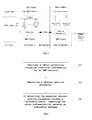
- Fig. 1 is a block diagram schematically illustrating functional modules of the BS and the MS according to an embodiment of the present invention.
- Fig. 2 is a flow chart illustrating the method carried out by the MS for reporting the state information according to the embodiment of the present invention.
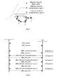
- Fig. 3 is a diagram schematically illustrating an example of the move of an MS from position A to position E in accordance with the embodiment of the present invention.
- Fig. 4 is a message sequence chart illustrating the messages exchanged between the BS and the MS corresponding to the move of the MS shown in the fig. 3 in accordance with the embodiment of the present invention.
- the embodiment is described in the context of a wireless network employing a layered coding technique.
- the documents IEEE Std 802.16eTM-2005 and IEEE Std 802.16 TM -2004/Cor1-2005 (Amendment and Corrigendum to IEEE Std 802.16-2004), available from IEEE, 3 Park Avenue New York, NY 10016-5997, USA and published on 28 February 2006 define certain aspects of such a wireless network.
- the embodiment described herein is placed in the frame of a network based on these documents, along with the changes indicated in the description. However, the invention should not be limited to the described network.
- Fig. 1 is block diagram schematically illustrating the functional modules of the Base Station (BS) and the Mobile Station (MS) for reporting state information, for example a state change information of joining or leaving a particular layer, in accordance with the embodiment of the present invention.
- BS Base Station
- MS Mobile Station
- the classifier module in the MAC layer is configured to transform the IP address of application packets to service flow ID, and to record the Qos (Quality of Service) parameter information of the upper layer Service Data Units (SDU).
- the Qos parameters information may includes layer type, e.g. Base Layer, Enhancement Layer 1 and etc., for each layer as well as typical Qos parameters such as guaranteed data rate, delay and jitter.
- the data packets of different layers will be stored in the corresponding buffer for scheduling, such as Base Layer Queue and at least one Enhancement Layer Queue.
- the scheduler module is configured to evaluate the Qos parameter information, combining with the feedback information reported from the PHY layer to allocate the bandwidth resource for each program based on a certain scheduling algorithm with the goal to increase the system effectiveness.
- the link adaptation module is in charge of collecting the state information conveyed in the indication messages from at least one MS.
- the channel estimation module is configured to measure one (or more) channel quality parameter (s) of a downlink channel, such as by estimating the CINR value of the downlink channel.
- the service management module negotiates with the BS during the service creation and captures the condition table, and is also configured to determine whether or not to send out an indication message based on the at least one channel quality parameter of the downlink channel estimated by the channel estimation module. If it is determined that a message is to be sent, the indication message, such as an MBS_IND message shown below, is sent out to the BS for the reporting of the MS's state information.
- the BS when an MS initiates a dynamic service addition (DSA) request for an MBS service to the BS, the BS will send a response message containing each available layer's information, its corresponding threshold CINR value and connection identifier (CID) for the requested MBS service to the MS, and the MS will store the layer type, threshold CINR value and CID as the effective reception condition information in a table in the local memory during the lifetime of the MBS service.
- the condition table can be stored in a device other than the MS. Therefore, in this application, the reception condition providing module is used to provide the reception condition information. But if the condition table is stored outside of the MS, the reception condition providing module should be able to enter into signal communication with the outside device so as to derive the reception condition information.
- Fig. 2 is a flow chart illustrating the method carried out by the MS for reporting the state information in accordance with the embodiment of the present invention.
- the MS derives a table containing reception condition information for an MBS service, which the MS wants to receive.
- the table is derived based on the following steps: when an MS sends a dynamic service addition (DSA) request to the BS requesting to join an MBS service during the establishment of the connection in the MAC layer, the BS transmits the DSA response message containing reception condition information so that the MS can derive the reception condition information from the received DSA response message; and the MS stores the derived reception information in a table of a storage device, and maintains the table during the lifetime of the multicast service.
- DSA dynamic service addition
- the MBS service contains 3 layers, i.e. base layer, enhancement layer 1 and enhancement layer 2, with each layer associated with a CID and an effective reception CINR.
- the reception information contained in the sample table means that if the actual value of the current CINR reaches a threshold value of 5 dB, the MS is eligible to receive the data from the base layer of the requested MBS service; if the actual value of current CINR reaches another threshold value of 14 dB, the MS is eligible to additionally receive data from the enhancement layer 1; and when reaching the 20 dB, the MS is able to receive all data from base layer, enhancement layer 1 and enhancement layer 2.
- the CID here in the table is used to identify the different layers of an MBS service.
- the reception condition information is used to indicate the conditions for triggering some actions, such as sending an indication message.
- the threshold values of CINR i.e. 5 db, 14 db and 20 db, are the conditions for triggering the MS to send a message indicating the state change of the MS, i.e. joining or leaving a particular layer.
- Fig. 3 is a diagram schematically illustrating an example of the move of an MS from position A to position E in accordance with the embodiment of the present invention.
- Fig. 4 is a message sequence chart illustrating the messages exchanged between the BS and the MS corresponding to the move of the MS shown in the fig. 3 in accordance with the embodiment of the present invention.
- there are three receiving areas which are the areas of enhancement layer 2, enhancement layer 1 and base layer from inside to outside.
- FIG. 3 there are three receiving areas, which are the areas of enhancement layer 2, enhancement layer 1 and base layer from inside to outside.
- the MS locating at position A intends to join an MBS service of 3-layers, so the MS generates a table indicating the reception condition information for the requested MBS service during the connection establishment, and sends a message to the BS to indicate the fact of joining the base layer.
- the MS finds the current CINR reaches the threshold value of enhancement layer 1. So it sends a message to the BS to indicate the joining enhancement layer 1.
- the MS is aware of the change of current CINR and sends to the BS a message indicating leaving enhancement layer 1, joining enhancement layer 1 and joining enhancement layer 2, separately.
- the indication message is transmitted on the control message connection in WiMAX to guarantee a transmission with low delay.
- the indication message can be transmitted by piggyback mode over the existing uplink connection with the advantage of reducing the probability of collision with other MSs.
- Table 2 MBS_IND message format Syntax Size Notes MBS_IND message format() ⁇ Management message type 8 bit Multicast CID 16 bit Type 1 bit 1: Join 0: Leave ⁇
- Management message type field it is used to indicate the control message type so as to be compatible with the current standard.
- Multicast CID field it is used to indicate the identifier of the connection, which can also be used to uniquely identify a layer of an MBS service.
- Type field it is used to indicate whether the MS joins or leaves a layer that is identified by the value of the Multicast CID field.
- the MBS_IND_ACK message is used by the BS to notify the MS of the acknowledgement of correctly receiving the MBS_IND message. It is known to one of the skilled in the art that the acknowledgement message is not always necessary under some circumstances.
- the MS measures a channel quality parameter, e.g. the CINR value from the downlink channel.
- a channel quality parameter e.g. the CINR value from the downlink channel.
- the estimated CINR value shall be an estimate of the CINR over the subcarriers of the preamble.
- the estimated CINR value shall be the average CINR on non-boosted data subcarriers of the zone.
- Another possible method for estimating the CINR value of a single message is to compute the ratio of the sum of the signal power and the sum of the residual error for each data sample, using the following function:
- r[k,n] is the received sample n within the message measured at time index k in frame units
- s[k,n] is the detected or pilot sample n within the message measured at time index k in frame units.
- the MS detects the measured channel quality parameter reaches a predetermined threshold value of the reception condition information, it will report its state information corresponding to the measured channel quality parameter by sending an indication message.
- the MS measures the channel quality parameter, for example the CINR value. And once the measured CINR value reaches a threshold value of the reception condition information, the MS will determine its current state information corresponding to the measured channel quality parameter and then send an indication message to the BS to report its state information, for example, the state change information of joining/leaving a particular layer.
- the signaling overhead is reduced because only the MSs satisfying the requirement of reception condition information send the report message. Furthermore, because the MS sends the report message right after it determines the channel quality satisfies one reception condition, the accuracy of the reporting mechanism is augmented.
- the BS dynamically adjusts the resource allocation with a scheduling algorithm so as to increase the system's effectiveness.
- the BS performs resource allocation among MBS services.
- the resource scheduling is done periodically and we assume that the transmit power across different sub-channels is fixed and does not change during service transmission. For the convenience of the reader, notations used below are shown in the table 3.
- an MS can be defined by the ratio of assigned bandwidth and expected bandwidth, denoting as . Assuming the mapping of the MCS mode for each layer is predefined in the BS and synchronized with each MS, the transmission of different layers respectively has different spectrum efficiencies. Thus we can define the utility ratio function for MS i in multicast group j as
- the utility ratio for program j is the summation of the utility ratio values for all subscribers, i.e.
- factor (b) can be met by reserving the minimal guaranteed bandwidth for each program, but utility ratio increment problem is NP-hard.
- DES dynamic exception satisfaction
- the bandwidth for the base layer region is reserved for each program.
- an order list will be created as a function of the number of subscribers at a given point in time: the most popular programs will be assigned more resources according to the following two approaches:
- step 3 which is fixed modulated by QPSK1/2.
- the following steps from 4 to 12 are used by the greedy algorithm to allocate the remaining bandwidth based on the program popularity indicated by the number of subscribers located in the region with effective reception capability for enhancement layers.
- the statistic value of the subscriber distribution of each program is calculated in step 4.
- the bandwidth is allocated in the order of the enhancement layers, in each scheduling round, a program is served according to the increasing popularity.
- Those programs with more subscribers capable of receiving an enhancement layer will go into upgrade processing by adding an enhancement layer or increasing resources until ⁇ max is reached (step 8).
- ⁇ min and ⁇ max can be set to a value between the boundaries ⁇ min and ⁇ max , e.g. the bandwidth can be divided by a mean value or by using a proportioned fairness algorithm (in step 10).
- the bandwidth can be divided by a mean value or by using a proportioned fairness algorithm (in step 10).
- a proportioned fairness algorithm in step 10.
- the iteration is done among video programs until the total available bandwidth is used up or all programs have already been served (step 7).
- the DES algorithm can run in polynomial time.
- the complexity has two components, the first one being the sorting of popularity, which can be bound by O(P*lg(P)), where P is the number of multicast programs.
- the second one is the bandwidth allocation in each layer, the complexity of which can be bound by O(P*L). Therefore the complexity is O(P*lg(P))+O(P*L).
- the number of programs in a system is a finite value, and a constant boundary E can be found for lg(P), lg(P) ⁇ E, thus the proposed algorithm can be run in polynomial time so as to improve the system's effectiveness.
- the reception condition information is not transmitted during the connection establishment, but transmitted in a dedicated message after the establishment of connection.
- the table is periodically updated by the MS through the signal communication between the MS and the BS after the table is initially generated by the MS.
- the conditions for triggering the action of reporting may take into account the configuration of an MS. For example, some MS would like to improve video quality by subscribing to more layers, other mobile hosts may take into account power consumption or decoding capability and thereby subscribe to a limited number of layers.
- the message reported is not limited to the message indicative of joining/leaving a particular layer.
- One of ordinary skill in the pertinent arts will appreciate that other kinds of messages can be used to indicate the state information of the MS.
- the MS can measure two or more channel quality parameters for more precise control.
- the variation downgrade/upgrade slope can be used as a criterion for triggering the action of reporting.
- the reception condition information should comprise these corresponding two or more channel quality parameters.
- the reception condition information just contains the fields of effective reception CINR and an identifier that can uniquely identify a layer. And in the report message there is a field indicating the action to the layer, e.g. joining or leaving a layer.
Landscapes
- Engineering & Computer Science (AREA)
- Computer Networks & Wireless Communication (AREA)
- Signal Processing (AREA)
- Quality & Reliability (AREA)
- Mobile Radio Communication Systems (AREA)
Abstract
Description
- The present invention relates to wireless communication, and more particularly, relates to a method and an apparatus for reporting state information of a receiver device.
- The IEEE 802.16 standard specifies a fixed and mobile Broadband Wireless Access (BWA) standard for a wireless Metropolitan Area Network (MAN). The IEEE 802.16 standard defines different physical layer technologies for different frequency bands.
- In current communication systems, multicast and broadcast techniques are employed for transmitting data from one source to multiple destinations. In order to effectively utilize radio resources, the IEEE 802.16e standard has introduced the Multicast and Broadcast Service (MBS) that standardizes the point to multi-point transmission in the mobile network. The MBS service may support not only the multicast and broadcast of low bit-rate message services such as text, but also the multicast and broadcast of high bit-rate multimedia services.
- Layered coding is a data representation technique in which the source data is partitioned into multiple layers. The layers are organized normally in a way that the lowest layer also called base layer contains the minimum information for intelligibility; the other layers also called enhancement layers contain additional information that incrementally improves the overall quality of the source data. When the layered coding technique is applied in a video codec, the video data is normally encoded into multiple layers including a base layer of comparatively low quality video and at least one enhancement layer of increasingly higher quality video. At the receiver side of a layered coding communication system, a decoder can be configured to choose to decode a particular subset of these layers to get a particular quality of the video according to its preference and decoding capability.
- Adaptive MCS (Modulation and Coding Scheme) is a key feature for WiMAX technology, wherein a higher level of MCS is employed in the area of good Signal to Noise Ratio (SNR); on the contrary, in the area of poor SNR, a relatively lower level of MCS is employed to guarantee the connection quality and link stability. In the MCS supported by the WiMAX, there are three categories of modulation types: QPSK (Quadrature Phase Shift Keying), 16QAM (Quadrature Amplitude Modulation) and 64QAM.
- To implement the adaptive MCS, one of important requirements is to acquire accurate feedback report of channel quality from the Mobile Stations (MS). Two kinds of mechanisms are defined in the standard for the MS to report the DL (Download Link) CINR (Carrier to Interference and Noise Ratio) value to the Base Station (BS):
- --the first one is REP-RSP (Channel measurement Report-Response) MAC message. The REP-RSP message in response to a REP-REQ message from the BS shall be sent by the MS to report estimation of the DL physical CINR or the effective CINR;
- --the second one is periodic CINR report with fast-feedback (CQICH) channel, wherein the BS may allocate a CQICH sub channel using a CQICH Control Information Element to provide a unicast uplink opportunity for periodic CINR reports (physical CINR or effective CINR), and the MS transmits channel quality information on the assigned CQICH of every frame.
- The reporting messages sent by the MSs will cause a certain amount of signaling overhead as a function of the frequency of the polling and the total number of subscribers. Therefore, it is desirable to provide a method for reporting state information with a smaller signaling overhead.
- According to an aspect of present invention, it provides a method for reporting state information of a receiver device in a multicast or broadcast network. The method comprises the steps of: the receiver device receives data from a channel; the receiver device measures a channel quality parameter (202); and in response to the channel quality parameter reaching a predetermined threshold value, the receiver device transmits state information of the receiver device corresponding to said measured channel quality parameter (203).
- According to an aspect of the present invention, it provides a receiver device for reporting state information in a multicast or broadcast network. The device comprises a channel estimation module and a service management module. The channel estimation module is configured to measure the channel quality parameter of downlink channel. And the service management module is configured to transmit state information of said receiver device in response to the cannel quality parameter reaching a predetermined threshold value, wherein the state information is determined corresponding to said measured channel quality parameter.
- According to an aspect of the present invention, it provides a device for resource allocation in a multicast or broadcast network in which data of a service is portioned into at least one layer. The device comprises a first module and a second module. The first module is configured to receive state information from at least one receiver device, wherein the state information is transmitted when channel quality bearing said service reaches a predetermined condition. And the second module is configured to adjust resource allocation of all services as a function of the received at least one receiver device's state information.
- According to an aspect of the present invention, because only the MSs that satisfy the requirement of reception condition information send the report message, the signaling overhead is greatly reduced.
- It is to be understood that both the foregoing general description and the following detailed description of the present invention are explanatory and exemplary only.
- The accompanying drawings, which are included to provide a further understanding of the invention and are incorporated in and constitute a part of this application, illustrate embodiment of the invention together with the description which serves to explain the principle of the invention. Therefore, the invention is not limited to the embodiment. In the drawings:
-
Fig. 1 is a block diagram schematically illustrating functional modules of the BS and the MS according to an embodiment of the present invention. -
Fig. 2 is a flow chart illustrating the method carried out by the MS for reporting the state information according to the embodiment of the present invention. -
Fig. 3 is a diagram schematically illustrating an example of the move of an MS from position A to position E in accordance with the embodiment of the present invention. -
Fig. 4 is a message sequence chart illustrating the messages exchanged between the BS and the MS corresponding to the move of the MS shown in thefig. 3 in accordance with the embodiment of the present invention. - The embodiment of the present invention will now be described in detail in conjunction with the drawings. In the following description, some detailed descriptions of known functions and configurations may be omitted for clarity and conciseness.
- The embodiment is described in the context of a wireless network employing a layered coding technique. For an example, the documents IEEE Std 802.16e™-2005 and IEEE Std 802.16™-2004/Cor1-2005 (Amendment and Corrigendum to IEEE Std 802.16-2004), available from IEEE, 3 Park Avenue New York, NY 10016-5997, USA and published on 28 February 2006 define certain aspects of such a wireless network. The embodiment described herein is placed in the frame of a network based on these documents, along with the changes indicated in the description.
However, the invention should not be limited to the described network. -
Fig. 1 is block diagram schematically illustrating the functional modules of the Base Station (BS) and the Mobile Station (MS) for reporting state information, for example a state change information of joining or leaving a particular layer, in accordance with the embodiment of the present invention. - At the BS's side:
- -When the layered coded video is delivered from the upper layer, the classifier module in the MAC layer is configured to transform the IP address of application packets to service flow ID, and to record the Qos (Quality of Service) parameter information of the upper layer Service Data Units (SDU). The Qos parameters information may includes layer type, e.g. Base Layer,
Enhancement Layer 1 and etc., for each layer as well as typical Qos parameters such as guaranteed data rate, delay and jitter. The data packets of different layers will be stored in the corresponding buffer for scheduling, such as Base Layer Queue and at least one Enhancement Layer Queue. - -The scheduler module is configured to evaluate the Qos parameter information, combining with the feedback information reported from the PHY layer to allocate the bandwidth resource for each program based on a certain scheduling algorithm with the goal to increase the system effectiveness.
- -The link adaptation module is in charge of collecting the state information conveyed in the indication messages from at least one MS.
- At the MS's side:
- -The channel estimation module is configured to measure one (or more) channel quality parameter (s) of a downlink channel, such as by estimating the CINR value of the downlink channel.
- -The service management module negotiates with the BS during the service creation and captures the condition table, and is also configured to determine whether or not to send out an indication message based on the at least one channel quality parameter of the downlink channel estimated by the channel estimation module. If it is determined that a message is to be sent, the indication message, such as an MBS_IND message shown below, is sent out to the BS for the reporting of the MS's state information. Wherein, when an MS initiates a dynamic service addition (DSA) request for an MBS service to the BS, the BS will send a response message containing each available layer's information, its corresponding threshold CINR value and connection identifier (CID) for the requested MBS service to the MS, and the MS will store the layer type, threshold CINR value and CID as the effective reception condition information in a table in the local memory during the lifetime of the MBS service. One person of ordinary skills in the relevant art will appreciate that the condition table can be stored in a device other than the MS. Therefore, in this application, the reception condition providing module is used to provide the reception condition information. But if the condition table is stored outside of the MS, the reception condition providing module should be able to enter into signal communication with the outside device so as to derive the reception condition information.
-
Fig. 2 is a flow chart illustrating the method carried out by the MS for reporting the state information in accordance with the embodiment of the present invention. - -In the
step 201, the MS derives a table containing reception condition information for an MBS service, which the MS wants to receive. - As an example, the table is derived based on the following steps: when an MS sends a dynamic service addition (DSA) request to the BS requesting to join an MBS service during the establishment of the connection in the MAC layer, the BS transmits the DSA response message containing reception condition information so that the MS can derive the reception condition information from the received DSA response message; and the MS stores the derived reception information in a table of a storage device, and maintains the table during the lifetime of the multicast service. Below is a sample table of a 3-layer MBS service:
Table 1: sample table of a 3-layers MBS service Layer Type CID Effective Reception CINR (dB) Base Layer 5000 5 Enhancement Layer 15001 14 Enhancement Layer 25002 20 - As can be seen from the table 1, it contains the fields of layer type, CID (connection identifier) and effective reception CINR, records of which can all be derived from the DSA response message. The MBS service contains 3 layers, i.e. base layer,
enhancement layer 1 andenhancement layer 2, with each layer associated with a CID and an effective reception CINR. The reception information contained in the sample table means that if the actual value of the current CINR reaches a threshold value of 5 dB, the MS is eligible to receive the data from the base layer of the requested MBS service; if the actual value of current CINR reaches another threshold value of 14 dB, the MS is eligible to additionally receive data from theenhancement layer 1; and when reaching the 20 dB, the MS is able to receive all data from base layer,enhancement layer 1 andenhancement layer 2. The CID here in the table is used to identify the different layers of an MBS service. - In one word, the reception condition information is used to indicate the conditions for triggering some actions, such as sending an indication message. As in the above table, the threshold values of CINR, i.e. 5 db, 14 db and 20 db, are the conditions for triggering the MS to send a message indicating the state change of the MS, i.e. joining or leaving a particular layer.
-
Fig. 3 is a diagram schematically illustrating an example of the move of an MS from position A to position E in accordance with the embodiment of the present invention. AndFig. 4 is a message sequence chart illustrating the messages exchanged between the BS and the MS corresponding to the move of the MS shown in thefig. 3 in accordance with the embodiment of the present invention. As shown in theFig. 3 , there are three receiving areas, which are the areas ofenhancement layer 2,enhancement layer 1 and base layer from inside to outside. As shown in theFig. 4 , the MS locating at position A intends to join an MBS service of 3-layers, so the MS generates a table indicating the reception condition information for the requested MBS service during the connection establishment, and sends a message to the BS to indicate the fact of joining the base layer. When the MS moves to the position B, the MS finds the current CINR reaches the threshold value ofenhancement layer 1. So it sends a message to the BS to indicate the joiningenhancement layer 1. And for the subsequent move to position C, D and E, the MS is aware of the change of current CINR and sends to the BS a message indicating leavingenhancement layer 1, joiningenhancement layer 1 and joiningenhancement layer 2, separately. Generally, the indication message is transmitted on the control message connection in WiMAX to guarantee a transmission with low delay. Since more than one indication message may be sent out at the same time by different MSs, collision is not avoidable. Therefore, several subsequent trials can be adopted in the uplink competition interval so as to improve reliability. Furthermore, if some uplink traffic is already running in the WiMAX, the indication message can be transmitted by piggyback mode over the existing uplink connection with the advantage of reducing the probability of collision with other MSs. - One example of a format of an indication message is shown below in table 2:
Table 2: MBS_IND message format Syntax Size Notes MBS_IND message format(){ Management message type 8 bit Multicast CID 16 bit Type 1 bit 1: Join 0: Leave } - Management message type field: it is used to indicate the control message type so as to be compatible with the current standard.
- Multicast CID field: it is used to indicate the identifier of the connection, which can also be used to uniquely identify a layer of an MBS service.
- Type field: it is used to indicate whether the MS joins or leaves a layer that is identified by the value of the Multicast CID field.
- The MBS_IND_ACK message is used by the BS to notify the MS of the acknowledgement of correctly receiving the MBS_IND message. It is known to one of the skilled in the art that the acknowledgement message is not always necessary under some circumstances.
- -In the
step 202, the MS measures a channel quality parameter, e.g. the CINR value from the downlink channel. - Many methods can be employed to estimate the CINR value of the channel.
- If the CINR estimation from the preamble is to be carried out, then the estimated CINR value shall be an estimate of the CINR over the subcarriers of the preamble.
- If the CINR estimation on a specific permutation zone is to be carried out, then the estimated CINR value shall be the average CINR on non-boosted data subcarriers of the zone.
- Another possible method for estimating the CINR value of a single message is to compute the ratio of the sum of the signal power and the sum of the residual error for each data sample, using the following function:
-

- Wherein r[k,n] is the received sample n within the message measured at time index k in frame units, and s[k,n] is the detected or pilot sample n within the message measured at time index k in frame units.
- -In the
step 203, if the MS detects the measured channel quality parameter reaches a predetermined threshold value of the reception condition information, it will report its state information corresponding to the measured channel quality parameter by sending an indication message. - The MS measures the channel quality parameter, for example the CINR value. And once the measured CINR value reaches a threshold value of the reception condition information, the MS will determine its current state information corresponding to the measured channel quality parameter and then send an indication message to the BS to report its state information, for example, the state change information of joining/leaving a particular layer.
- According to the embodiment of the present invention, the signaling overhead is reduced because only the MSs satisfying the requirement of reception condition information send the report message. Furthermore, because the MS sends the report message right after it determines the channel quality satisfies one reception condition, the accuracy of the reporting mechanism is augmented.
- Optionally, in addition to the above steps, based on the statistical information on all MBS services derived from the indication messages sent by MSs, the BS dynamically adjusts the resource allocation with a scheduling algorithm so as to increase the system's effectiveness.
- To achieve overall efficient spectral utilization for the MBS service, the BS performs resource allocation among MBS services. The resource scheduling is done periodically and we assume that the transmit power across different sub-channels is fixed and does not change during service transmission. For the convenience of the reader, notations used below are shown in the table 3.
Table 3: Notations list λ b Base layer rate, 
Enhancement layer l rate in multicast group j λmin,λmax Minimal and Maximum value for enhancement layer 
Expected bandwidth for receiver i in multicast group j 
Spectrum Efficiency of layer l in multicast group j 
Assigned bandwidth for receiver i in multicast group j 
Utility ratio(IFR) for receiver i in multicast group j bj Bandwidth assigned for program j li Enhancement layer number of program j Uj The utility ratio of program j U The system utility ratio B Total available bandwidth in the system p Total number of video program in the system 
Number of receivers with enhancement layer reception capability in the program j L Maximum number of enhancement layer - The satisfaction of an MS can be defined by the ratio of assigned bandwidth and expected bandwidth, denoting as. Assuming the mapping of the MCS mode for each layer is predefined in the BS and synchronized with each MS, the transmission of different layers respectively has different spectrum efficiencies. Thus we can define the utility ratio function for MS i in multicast group j as

-

- which can reflect the combined consideration of channel spectrum efficiency and user satisfaction. The utility ratio for program j is the summation of the utility ratio values for all subscribers, i.e.
-

- So, the system utility ratio
-

- is defined as the total utility ratio value for all programs or MBS services. In order to increase the system utility ratio U, two factors need to be considered:
- (a)

- (b)

- The requirement of factor (b) can be met by reserving the minimal guaranteed bandwidth for each program, but utility ratio increment problem is NP-hard.
- A greedy algorithm named dynamic exception satisfaction (DES) is proposed to carry out the resource allocation.
- Firstly, the bandwidth for the base layer region is reserved for each program. Secondly, for enhancement layer, an order list will be created as a function of the number of subscribers at a given point in time: the most popular programs will be assigned more resources according to the following two approaches:
- (a) Allow all enhancement layers for this program
- (b) Allocate more resources for at least one enhancement layer
- On the other hand, the less popular programs will be downgraded by releasing some enhancement layers or reducing bandwidth allocation.
- Below is a pseudo-code for the algorithm.
-
- Step 1: Set available bandwidth BW=B,
- Step 2: Generate condition table of MCS and layer;
- Step 3: BW←BW-λ b *P // reserve base layer for each program
-
- Step 4: Statistics receiver number for each program

//by feedback - Step 5: ∀j∈P, Sorting // sort popularity exponent among all programs

- Step 6: l ← 1: Start from the
enhancement layer 1 - Step 7: While (BW>0) && (some programs are not served) Switch (∀j∈P)
- Step 8: Case Top α% popular program:

- Step 9: Case Bottom β% program: if


- Step 10: Case Normal program: if

, break;
End Switch - 11.Calculate bj for this program , BW← BW- bj
- 12.l ← l +1 //Move to next layer End While
- Considering the requirement of factor (b), we first reserve the resources for the base layer of each video program or MBS service λmin in step 3, which is fixed modulated by QPSK1/2.
- The following steps from 4 to 12 are used by the greedy algorithm to allocate the remaining bandwidth based on the program popularity indicated by the number of subscribers located in the region with effective reception capability for enhancement layers. At the beginning of each scheduling processing, the statistic value of the subscriber distribution of each program is calculated in step 4. Then the bandwidth is allocated in the order of the enhancement layers, in each scheduling round, a program is served according to the increasing popularity. Those programs with more subscribers capable of receiving an enhancement layer will go into upgrade processing by adding an enhancement layer or increasing resources until λmax is reached (step 8). On the contrary, the bottom programs with fewer receivers should release resources by decreasing the data rate to λmin. If for a layer λmin=0, this layer will be removed. For a normal program,can be set to a value between the boundaries λmin and λmax, e.g. the bandwidth can be divided by a mean value or by using a proportioned fairness algorithm (in step 10). Considering the dependence among layers, if one layer is removed, the consecutive higher layers will also be eliminated. The iteration is done among video programs until the total available bandwidth is used up or all programs have already been served (step 7).

- The DES algorithm can run in polynomial time. The complexity has two components, the first one being the sorting of popularity, which can be bound by O(P*lg(P)), where P is the number of multicast programs. The second one is the bandwidth allocation in each layer, the complexity of which can be bound by O(P*L). Therefore the complexity is O(P*lg(P))+O(P*L). Generally speaking, the number of programs in a system is a finite value, and a constant boundary E can be found for lg(P), lg(P)<E, thus the proposed algorithm can be run in polynomial time so as to improve the system's effectiveness.
- According to a variant of the present embodiment, the reception condition information is not transmitted during the connection establishment, but transmitted in a dedicated message after the establishment of connection.
- According to a variant of the present embodiment, the table is periodically updated by the MS through the signal communication between the MS and the BS after the table is initially generated by the MS.
- According to a variant of the present embodiment, the conditions for triggering the action of reporting may take into account the configuration of an MS. For example, some MS would like to improve video quality by subscribing to more layers, other mobile hosts may take into account power consumption or decoding capability and thereby subscribe to a limited number of layers.
- According to a variant of the present embodiment, the message reported is not limited to the message indicative of joining/leaving a particular layer. One of ordinary skill in the pertinent arts will appreciate that other kinds of messages can be used to indicate the state information of the MS.
- According to a variant of the present embodiment, a man skilled in the relevant art will appreciate that the MS can measure two or more channel quality parameters for more precise control. For example, besides the CINR, the variation downgrade/upgrade slope can be used as a criterion for triggering the action of reporting. Correspondingly, the reception condition information should comprise these corresponding two or more channel quality parameters.
- According to a variant of the present embodiment, the reception condition information just contains the fields of effective reception CINR and an identifier that can uniquely identify a layer. And in the report message there is a field indicating the action to the layer, e.g. joining or leaving a layer.
- A number of implementations have been described. Nevertheless, it will be understood that various modifications may be made. For example, elements of different implementations may be combined, supplemented, modified, or removed to produce other implementations. Additionally, one of ordinary skill will understand that other structures and processes may be substituted for those disclosed and the resulting implementations will perform at least substantially the same function(s), in at least substantially the same way(s), to achieve at least substantially the same result(s) as the implementations disclosed. Accordingly, these and other implementations are contemplated by this application and are within the scope of the invention.
Claims (11)
- A method for reporting state information of a receiver device in a multicast or broadcast network, characterized, at the side of the receiver device, by the steps of:- Receiving data from a channel;- Measuring a channel quality parameter (202); and- In response to the channel quality parameter reaching a predetermined threshold value , transmitting state information of the receiver device corresponding to said measured channel quality parameter (203).
- The method according to claim 1, characterized by further comprising the steps of:Deriving reception condition information of a service indicating at least one predetermined threshold value for triggering the transmission of the state information of said receiver device (201).
- The method according to claim 2, characterized in that the reception condition information is derived by the receiver device during the establishment of the connection in the MAC layer.
- The method according to any one of claims 1 to 3,
characterized in that said channel quality parameter is a parameter or a combination of at least two parameters that can reflect the channel condition. - The method according to claim 2, characterized in that said reception condition information is periodically updated.
- The method according to claim 2, characterized in that data of said service is partitioned into at least one layer, and said receiver device's state information is the state change information of joining or leaving a particular layer.
- The method according to claim 6, characterized in that said reception condition information comprises fields of threshold value of channel quality parameter and layer identifier uniquely identifying a layer.
- A receiver device for reporting state information in a multicast or broadcast network, characterized by comprising:- a channel estimation module configured to measure the channel quality parameter of downlink channel; and- a service management module configured to transmit state information of said receiver device in response to the cannel quality parameter reaching a predetermined threshold value, wherein the state information is determined corresponding to said measured channel quality parameter.
- The receiver device according to claim 8,
characterized by further comprising:- a reception condition providing module configured to providing reception condition information of a service indicating at least one predetermined threshold value for triggering the transmission of state information of said receiver device. - The receiver device according to claim 8 or 9,
characterized in that said service management module further comprises the functions of deriving said reception condition information of said service from the sender device during the establishment of connection in MAC layer and storing said reception condition information in a storage media. - A device for resource allocation in a multicast or broadcast network in which data of a service is portioned into at least one layer, characterized by comprising:- a first module configured to receive state information from at least one receiver device, wherein the state information is transmitted when channel quality bearing said service reaches a predetermined condition; and- a second module configured to adjust resource allocation of all services as a function of the received at least one receiver device's state information.
Priority Applications (7)
| Application Number | Priority Date | Filing Date | Title |
|---|---|---|---|
| EP08305333A EP2139179A1 (en) | 2008-06-26 | 2008-06-26 | Method and apparatus for reporting state information |
| EP09161708.4A EP2139271B1 (en) | 2008-06-26 | 2009-06-02 | Method and apparatus for reporting state information |
| US12/456,321 US8437717B2 (en) | 2008-06-26 | 2009-06-16 | Method and apparatus for reporting state information |
| TW098120521A TWI462517B (en) | 2008-06-26 | 2009-06-19 | Method and apparatus for reporting state information |
| JP2009149988A JP5675065B2 (en) | 2008-06-26 | 2009-06-24 | Method and apparatus for reporting status information |
| KR1020090057073A KR101563746B1 (en) | 2008-06-26 | 2009-06-25 | Method and apparatus for reporting state information |
| CN200910150277.1A CN101616362B (en) | 2008-06-26 | 2009-06-25 | Method and apparatus for reporting state information |
Applications Claiming Priority (1)
| Application Number | Priority Date | Filing Date | Title |
|---|---|---|---|
| EP08305333A EP2139179A1 (en) | 2008-06-26 | 2008-06-26 | Method and apparatus for reporting state information |
Publications (1)
| Publication Number | Publication Date |
|---|---|
| EP2139179A1 true EP2139179A1 (en) | 2009-12-30 |
Family
ID=40070725
Family Applications (2)
| Application Number | Title | Priority Date | Filing Date |
|---|---|---|---|
| EP08305333A Withdrawn EP2139179A1 (en) | 2008-06-26 | 2008-06-26 | Method and apparatus for reporting state information |
| EP09161708.4A Active EP2139271B1 (en) | 2008-06-26 | 2009-06-02 | Method and apparatus for reporting state information |
Family Applications After (1)
| Application Number | Title | Priority Date | Filing Date |
|---|---|---|---|
| EP09161708.4A Active EP2139271B1 (en) | 2008-06-26 | 2009-06-02 | Method and apparatus for reporting state information |
Country Status (6)
| Country | Link |
|---|---|
| US (1) | US8437717B2 (en) |
| EP (2) | EP2139179A1 (en) |
| JP (1) | JP5675065B2 (en) |
| KR (1) | KR101563746B1 (en) |
| CN (1) | CN101616362B (en) |
| TW (1) | TWI462517B (en) |
Cited By (1)
| Publication number | Priority date | Publication date | Assignee | Title |
|---|---|---|---|---|
| WO2013157916A1 (en) * | 2012-04-16 | 2013-10-24 | Mimos Berhad | Apparatus for efficient multicast transmission and method thereof |
Families Citing this family (11)
| Publication number | Priority date | Publication date | Assignee | Title |
|---|---|---|---|---|
| US20120185906A1 (en) * | 2009-10-02 | 2012-07-19 | Nederlandse Organisatie Voor Toegepast -Natuurwetenschappelijk Onderzoek Tno | Scalable Video Controls Bandwidth Allocation to Data Services |
| WO2012154325A1 (en) | 2011-04-01 | 2012-11-15 | Interdigital Patent Holdings, Inc. | Method and apparatus for controlling connectivity to a network |
| US20130145402A1 (en) * | 2011-12-02 | 2013-06-06 | Verizon Patent And Licensing Inc. | Video on demand broadcast services |
| GB201208323D0 (en) | 2012-01-26 | 2012-06-27 | Samsung Electronics Co Ltd | Processing state information |
| GB2498781B (en) | 2012-01-26 | 2014-12-17 | Samsung Electronics Co Ltd | Processing state information |
| CN104396161B (en) * | 2012-05-14 | 2019-03-15 | 三星电子株式会社 | Method and apparatus for processing state information in a communication system |
| CN106464925B (en) | 2014-01-29 | 2020-04-14 | 皇家Kpn公司 | Build a streaming presentation of events |
| US11265359B2 (en) | 2014-10-14 | 2022-03-01 | Koninklijke Kpn N.V. | Managing concurrent streaming of media streams |
| CN104883400A (en) * | 2015-05-22 | 2015-09-02 | 中国石油大学(华东) | Case-based cloud service management decision method |
| CN106656580B (en) * | 2016-11-29 | 2020-06-26 | 华为技术有限公司 | Service state migration method and device |
| CN106507485A (en) * | 2016-12-09 | 2017-03-15 | 北京邮电大学 | A quality-of-service-oriented wireless layered multicast transmission resource allocation method |
Citations (3)
| Publication number | Priority date | Publication date | Assignee | Title |
|---|---|---|---|---|
| EP1641302A1 (en) * | 2004-09-27 | 2006-03-29 | Matsushita Electric Industrial Co., Ltd. | Anonymous uplink measurement report in a wireless communication system |
| WO2007046734A1 (en) * | 2005-10-21 | 2007-04-26 | Telefonaktiebolaget L M Ericsson (Publ) | Apparatus and method for measurement reporting in a cellular telecommunications system |
| WO2007094734A1 (en) * | 2006-02-15 | 2007-08-23 | Telefonaktiebolaget Lm Ericsson (Publ) | Coordinated node b radio resource management measurements |
Family Cites Families (82)
| Publication number | Priority date | Publication date | Assignee | Title |
|---|---|---|---|---|
| US5706290A (en) * | 1994-12-15 | 1998-01-06 | Shaw; Venson | Method and apparatus including system architecture for multimedia communication |
| US5511067A (en) * | 1994-06-17 | 1996-04-23 | Qualcomm Incorporated | Layered channel element in a base station modem for a CDMA cellular communication system |
| US6055242A (en) * | 1996-03-20 | 2000-04-25 | Lucent Technologies Inc. | Method and apparatus enabling synchronous transfer mode, variable length and packet mode access for multiple services over a broadband communication network |
| SE9601606D0 (en) * | 1996-04-26 | 1996-04-26 | Ericsson Telefon Ab L M | Ways for radio telecommunication systems |
| US6148005A (en) * | 1997-10-09 | 2000-11-14 | Lucent Technologies Inc | Layered video multicast transmission system with retransmission-based error recovery |
| DE69939781D1 (en) * | 1998-10-30 | 2008-12-04 | Broadcom Corp | CABLE MODEM SYSTEM |
| US7054635B1 (en) * | 1998-11-09 | 2006-05-30 | Telefonaktiebolaget Lm Ericsson (Publ) | Cellular communications network and method for dynamically changing the size of a cell due to speech quality |
| US6614936B1 (en) * | 1999-12-03 | 2003-09-02 | Microsoft Corporation | System and method for robust video coding using progressive fine-granularity scalable (PFGS) coding |
| US6963544B1 (en) * | 1999-12-10 | 2005-11-08 | Lucent Technologies Inc. | System for statistically multiplexing real-time and non-real-time voice and data traffic in a wireless system |
| US6539030B1 (en) * | 2000-02-07 | 2003-03-25 | Qualcomm Incorporated | Method and apparatus for providing configurable layers and protocols in a communications system |
| US20020091991A1 (en) * | 2000-05-11 | 2002-07-11 | Castro Juan Carlos | Unified real-time microprocessor computer |
| US6816194B2 (en) * | 2000-07-11 | 2004-11-09 | Microsoft Corporation | Systems and methods with error resilience in enhancement layer bitstream of scalable video coding |
| US6862270B1 (en) * | 2000-07-14 | 2005-03-01 | At&T Corp. | Architectural reference model for QoS-driven wireless LANs |
| US7095754B2 (en) * | 2000-11-03 | 2006-08-22 | At&T Corp. | Tiered contention multiple access (TCMA): a method for priority-based shared channel access |
| US20020142721A1 (en) * | 2001-03-29 | 2002-10-03 | Motorola, Inc. | Method and device for selecting a wireless communication path |
| ES2186531B1 (en) * | 2001-04-19 | 2005-03-16 | Diseño De Sistemas En Silicio, S.A. | PROCEDURE FOR MULTIPLE AND MULTIPLE DATA TRANSMISSION FOR A MULTI-USER DIGITAL DATA TRANSMISSION SYSTEM POINT TO MULTIPOINT ON ELECTRICAL NETWORK. |
| US7570656B2 (en) * | 2001-06-18 | 2009-08-04 | Yitran Communications Ltd. | Channel access method for powerline carrier based media access control protocol |
| AU2002328209A1 (en) * | 2001-09-13 | 2003-03-24 | Redline Communications Inc. | Hierarchical modulation |
| US7535913B2 (en) * | 2002-03-06 | 2009-05-19 | Nvidia Corporation | Gigabit ethernet adapter supporting the iSCSI and IPSEC protocols |
| US7177295B1 (en) * | 2002-03-08 | 2007-02-13 | Scientific Research Corporation | Wireless routing protocol for ad-hoc networks |
| AU2003237236A1 (en) * | 2002-05-24 | 2003-12-12 | Kodiak Networks, Inc. | Dispatch service architecture framework |
| US7386049B2 (en) * | 2002-05-29 | 2008-06-10 | Innovation Management Sciences, Llc | Predictive interpolation of a video signal |
| JP3840435B2 (en) * | 2002-07-05 | 2006-11-01 | 松下電器産業株式会社 | Radio communication base station apparatus, radio communication mobile station apparatus, and radio communication method |
| JP3853765B2 (en) * | 2002-11-08 | 2006-12-06 | Necインフロンティア株式会社 | Packet compression method, packet restoration method, packet compression method, and packet restoration method |
| US8054880B2 (en) * | 2004-12-10 | 2011-11-08 | Tut Systems, Inc. | Parallel rate control for digital video encoder with multi-processor architecture and picture-based look-ahead window |
| SE0300047D0 (en) * | 2003-01-08 | 2003-01-08 | Ericsson Telefon Ab L M | MBMS in UTRAN |
| US7385951B2 (en) * | 2003-02-15 | 2008-06-10 | Lucent Technologies Inc. | Methods of transmitting and signaling over a reverse link in wireless systems |
| JP2004266503A (en) * | 2003-02-28 | 2004-09-24 | Matsushita Electric Ind Co Ltd | Video transmission system |
| ATE406010T1 (en) * | 2003-03-21 | 2008-09-15 | Ericsson Telefon Ab L M | METHOD AND DEVICE FOR CONNECTION ADJUSTMENT |
| US7313814B2 (en) * | 2003-04-01 | 2007-12-25 | Microsoft Corporation | Scalable, error resilient DRM for scalable media |
| DE60311015T2 (en) * | 2003-05-09 | 2007-08-02 | Telefonaktiebolaget Lm Ericsson (Publ) | SYSTEM AND METHOD FOR DATA INTERMEDIATE STORAGE AND DISTRIBUTION IN A WIRELESS COMMUNICATION NETWORK |
| EP1478198B1 (en) * | 2003-05-12 | 2006-03-22 | Matsushita Electric Industrial Co., Ltd. | Method and apparatus for performing inter-frequency measurements |
| US7961714B1 (en) * | 2004-05-11 | 2011-06-14 | Nortel Networks Limited | Providing packet-based multimedia services via a circuit bearer |
| US7746849B2 (en) * | 2003-07-30 | 2010-06-29 | Nortel Networds Limited | Providing packet-based multimedia services via a circuit bearer |
| US7460543B2 (en) * | 2003-08-13 | 2008-12-02 | Panasonic Corporation | Method and system for scheduling traffic in a wireless network |
| US7079552B2 (en) * | 2003-09-09 | 2006-07-18 | Harris Corporation | Mobile ad hoc network (MANET) with quality-of-service (QoS) protocol hierarchy and related methods |
| US7394826B2 (en) * | 2003-09-09 | 2008-07-01 | Harris Corporation | Mobile ad hoc network (MANET) providing quality-of-service (QoS) based unicast and multicast features |
| AU2003274013A1 (en) * | 2003-10-15 | 2005-05-11 | Ntt Docomo, Inc | Apparatus and method for controlling an operation of a plurality of communication layers |
| CN1879389B (en) * | 2003-10-15 | 2010-08-18 | 株式会社Ntt都科摩 | Apparatus and method for controlling operation of multiple communication layers in a layered communication environment |
| EP1528722A1 (en) * | 2003-10-31 | 2005-05-04 | Siemens Mobile Communications S.p.A. | Fast signalling procedure for streaming services quality of service management in wireless networks |
| US7181170B2 (en) * | 2003-12-22 | 2007-02-20 | Motorola Inc. | Apparatus and method for adaptive broadcast transmission |
| US7353279B2 (en) * | 2004-01-08 | 2008-04-01 | Hughes Electronics Corporation | Proxy architecture for providing quality of service(QoS) reservations |
| US20050170782A1 (en) * | 2004-02-04 | 2005-08-04 | Nokia Corporation | Method and apparatus to compensate quantization error of channel quality report |
| GB2416269A (en) * | 2004-04-16 | 2006-01-18 | Nokia Corp | Cell selection and re-selection |
| JP4352976B2 (en) * | 2004-04-20 | 2009-10-28 | 株式会社日立製作所 | Receiving apparatus and receiving method |
| US7979072B2 (en) * | 2004-06-04 | 2011-07-12 | Nortel Networks Limited | Method and system for soft handoff in mobile broadband systems |
| EP1610502B1 (en) * | 2004-06-21 | 2011-08-03 | Panasonic Corporation | Adaptive and scalable QOS architecture for single-bearer multicast/broadcast services |
| DE602004005842T2 (en) * | 2004-06-21 | 2007-09-20 | Matsushita Electric Industrial Co., Ltd., Kadoma | Scalable and adaptive QoS architecture for multichannel multicast / broadcast services |
| GB2418267A (en) * | 2004-09-08 | 2006-03-22 | Qinetiq Ltd | Shared resource management |
| EP1641189B1 (en) * | 2004-09-27 | 2010-05-19 | Panasonic Corporation | Error ratio measurement in the radio link control layer for quality of service control in a wireless communication system |
| KR100770876B1 (en) * | 2004-09-30 | 2007-10-26 | 삼성전자주식회사 | Method and apparatus for frequency-selection when session start in mbms system |
| KR100617835B1 (en) * | 2005-01-05 | 2006-08-28 | 삼성전자주식회사 | Apparatus and method for transmitting/receiving a channel quality information in a communication system |
| US7725799B2 (en) * | 2005-03-31 | 2010-05-25 | Qualcomm Incorporated | Power savings in hierarchically coded modulation |
| US7756206B2 (en) * | 2005-04-13 | 2010-07-13 | Nokia Corporation | FGS identification in scalable video coding |
| KR101280096B1 (en) | 2005-06-29 | 2013-06-28 | 컴퓨메딕스 리미티드 | Sensor Assembly with Conductive Bridge |
| US7778217B2 (en) * | 2005-07-19 | 2010-08-17 | Samsung Electronics Co., Ltd | System and method for scheduling uplink in a communication system |
| US8189659B2 (en) * | 2005-08-30 | 2012-05-29 | Thomson Licensing | Cross-layer optimization for scalable video multicast over IEEE 802.11 wireless local area networks |
| GB2430581B (en) * | 2005-09-21 | 2010-03-10 | King S College London | Access router selection method |
| US7567543B2 (en) * | 2005-10-24 | 2009-07-28 | Nec Laboratories America, Inc. | Method and apparatus for cross layer resource allocation for wireless backhaul networks |
| GB2433677A (en) * | 2005-10-31 | 2007-06-27 | Israel Aircraft Ind Ltd | Medium access control (MAC) method and system for dynamic time slot allocation and QoS priority access in a mobile ad hoc network (MANET) |
| KR100984694B1 (en) * | 2005-11-08 | 2010-10-01 | 노키아 코포레이션 | System and method for providing feedback and forward transmission for remote interaction in rich media applications |
| KR100668665B1 (en) * | 2005-11-22 | 2007-01-12 | 한국전자통신연구원 | How to Switch Channel Modes in a Wireless Mobile Internet System |
| US7653087B2 (en) * | 2006-01-06 | 2010-01-26 | Fujitsu Limited | Methods of synchronizing subscriber stations to communications networks |
| US20070189304A1 (en) * | 2006-01-27 | 2007-08-16 | Nokia Corporation | MAC-driven transport block size selection at a physical layer |
| US8396134B2 (en) * | 2006-07-21 | 2013-03-12 | Vidyo, Inc. | System and method for scalable video coding using telescopic mode flags |
| JP4970151B2 (en) * | 2006-08-21 | 2012-07-04 | 株式会社エヌ・ティ・ティ・ドコモ | Wireless communication terminal and wireless communication method |
| US8271043B2 (en) * | 2006-08-21 | 2012-09-18 | Qualcomm Incorporated | Approach to a unified SU-MIMO/MU-MIMO operation |
| CN101507302A (en) * | 2006-08-21 | 2009-08-12 | 交互数字技术公司 | Resource allocation, scheduling, and signaling for grouping real time services |
| US7684430B2 (en) * | 2006-09-06 | 2010-03-23 | Hitachi, Ltd. | Frame-based aggregation and prioritized channel access for traffic over wireless local area networks |
| KR100736728B1 (en) * | 2006-09-20 | 2007-07-09 | 한국전자통신연구원 | Apparatus and Method for Resource Allocation in Band Adaptive Modulation and Coding Mode for Broadband Wireless Access Systems |
| MY164442A (en) * | 2006-10-23 | 2017-12-15 | Interdigital Tech Corp | Method and apparatus for sending a channel quality indication via a shared channel |
| AU2007309044B2 (en) * | 2006-10-23 | 2011-04-28 | Vidyo, Inc. | System and method for scalable video coding using telescopic mode flags |
| WO2008066432A1 (en) * | 2006-11-30 | 2008-06-05 | Telefonaktiebolaget L M Ericsson (Publ) | Method and apparatus for reducing the signalling bandwidth load by reporting measurements in differential manner in a multicast message |
| US7899451B2 (en) * | 2007-07-20 | 2011-03-01 | Jianhong Hu | OWA converged network access architecture and method |
| TW200922185A (en) * | 2007-09-26 | 2009-05-16 | Packetvideo Corp | System and method for receiving broadcast multimedia on a mobile device |
| WO2009039638A1 (en) * | 2007-09-28 | 2009-04-02 | Pin-Han Ho | A robust system and method for wireless data multicasting using superposition modulation |
| US8451803B2 (en) * | 2007-10-05 | 2013-05-28 | Qualcomm Incorporated | Methods and apparatus for managing measurement behavior of DRX mode UE |
| KR100937590B1 (en) * | 2007-10-23 | 2010-01-20 | 한국전자통신연구원 | Multi-quality service video contents providing system and its upgrade method |
| KR20090079838A (en) * | 2008-01-17 | 2009-07-22 | 엘지전자 주식회사 | IPTV reception system and its data processing method |
| WO2009146132A2 (en) * | 2008-04-04 | 2009-12-03 | Powerwave Cognition, Inc. | Methods and systems for a mobile, broadband, routable internet |
| US20110164527A1 (en) * | 2008-04-04 | 2011-07-07 | Mishra Rajesh K | Enhanced wireless ad hoc communication techniques |
| CN102017491B (en) * | 2008-04-29 | 2014-09-17 | 汤姆逊许可公司 | Method and system for adjusting forward error correction in multicast in wireless network |
-
2008
- 2008-06-26 EP EP08305333A patent/EP2139179A1/en not_active Withdrawn
-
2009
- 2009-06-02 EP EP09161708.4A patent/EP2139271B1/en active Active
- 2009-06-16 US US12/456,321 patent/US8437717B2/en active Active
- 2009-06-19 TW TW098120521A patent/TWI462517B/en not_active IP Right Cessation
- 2009-06-24 JP JP2009149988A patent/JP5675065B2/en not_active Expired - Fee Related
- 2009-06-25 CN CN200910150277.1A patent/CN101616362B/en active Active
- 2009-06-25 KR KR1020090057073A patent/KR101563746B1/en not_active Expired - Fee Related
Patent Citations (3)
| Publication number | Priority date | Publication date | Assignee | Title |
|---|---|---|---|---|
| EP1641302A1 (en) * | 2004-09-27 | 2006-03-29 | Matsushita Electric Industrial Co., Ltd. | Anonymous uplink measurement report in a wireless communication system |
| WO2007046734A1 (en) * | 2005-10-21 | 2007-04-26 | Telefonaktiebolaget L M Ericsson (Publ) | Apparatus and method for measurement reporting in a cellular telecommunications system |
| WO2007094734A1 (en) * | 2006-02-15 | 2007-08-23 | Telefonaktiebolaget Lm Ericsson (Publ) | Coordinated node b radio resource management measurements |
Cited By (1)
| Publication number | Priority date | Publication date | Assignee | Title |
|---|---|---|---|---|
| WO2013157916A1 (en) * | 2012-04-16 | 2013-10-24 | Mimos Berhad | Apparatus for efficient multicast transmission and method thereof |
Also Published As
| Publication number | Publication date |
|---|---|
| JP5675065B2 (en) | 2015-02-25 |
| JP2010011456A (en) | 2010-01-14 |
| EP2139271A1 (en) | 2009-12-30 |
| TW201001970A (en) | 2010-01-01 |
| US8437717B2 (en) | 2013-05-07 |
| US20090325526A1 (en) | 2009-12-31 |
| CN101616362A (en) | 2009-12-30 |
| KR101563746B1 (en) | 2015-11-06 |
| KR20100002201A (en) | 2010-01-06 |
| TWI462517B (en) | 2014-11-21 |
| CN101616362B (en) | 2015-03-11 |
| EP2139271B1 (en) | 2019-02-27 |
Similar Documents
| Publication | Publication Date | Title |
|---|---|---|
| EP2139271B1 (en) | Method and apparatus for reporting state information | |
| US12127201B2 (en) | Resource block candidate selection technique employing packet scheduling in wireless communication systems | |
| US8605610B2 (en) | Method and apparatus for link adaptive multicast/broadcast transmission and reception | |
| US9831998B2 (en) | Apparatus and method for feeding back channel quality information and scheduling apparatus and method using the same in a wireless communication system | |
| US7821982B2 (en) | Packet communications taking into account channel quality and buffered data amount | |
| US8649273B2 (en) | Method for reporting a transmission channel quality | |
| CN1972515A (en) | Method and apparatus for transmitting/receiving channel quality information (cqi) in a wireless communication system | |
| US8111710B2 (en) | Method and apparatus for receiving feedback corresponding to multicast broadcast service | |
| WO2008130156A1 (en) | Grouping based resource allocation method, method for transmitting signal using the same, and grouping based resource allocation controller | |
| US20100322102A1 (en) | Uplink feedback in a multimedia broadcast/multicast services (mbms) wireless communications system | |
| US8014349B2 (en) | Apparatus and method for transmitting/receiving signal in a communication system | |
| CN101785205B (en) | Method of using persistent scheduling control channel transmission | |
| Kim et al. | Piggybacking Scheme of MAP IE for Minimizing MAC Overhead in the IEEE 802.16 e OFDMA Systems | |
| Cho et al. | MCS selection algorithms for a persistent allocation scheme to accommodate VoIP services in IEEE 802.16 e OFDMA system |
Legal Events
| Date | Code | Title | Description |
|---|---|---|---|
| PUAI | Public reference made under article 153(3) epc to a published international application that has entered the european phase |
Free format text: ORIGINAL CODE: 0009012 |
|
| AK | Designated contracting states |
Kind code of ref document: A1 Designated state(s): AT BE BG CH CY CZ DE DK EE ES FI FR GB GR HR HU IE IS IT LI LT LU LV MC MT NL NO PL PT RO SE SI SK TR |
|
| AX | Request for extension of the european patent |
Extension state: AL BA MK RS |
|
| RAP1 | Party data changed (applicant data changed or rights of an application transferred) |
Owner name: THOMSON LICENSING |
|
| AKY | No designation fees paid | ||
| REG | Reference to a national code |
Ref country code: DE Ref legal event code: 8566 |
|
| STAA | Information on the status of an ep patent application or granted ep patent |
Free format text: STATUS: THE APPLICATION IS DEEMED TO BE WITHDRAWN |
|
| 18D | Application deemed to be withdrawn |
Effective date: 20100802 |