EP2139162B1 - Configuration d'un dispositif électronique intelligent - Google Patents
Configuration d'un dispositif électronique intelligent Download PDFInfo
- Publication number
- EP2139162B1 EP2139162B1 EP08159063A EP08159063A EP2139162B1 EP 2139162 B1 EP2139162 B1 EP 2139162B1 EP 08159063 A EP08159063 A EP 08159063A EP 08159063 A EP08159063 A EP 08159063A EP 2139162 B1 EP2139162 B1 EP 2139162B1
- Authority
- EP
- European Patent Office
- Prior art keywords
- data
- verification data
- module
- modules
- inter
- Prior art date
- Legal status (The legal status is an assumption and is not a legal conclusion. Google has not performed a legal analysis and makes no representation as to the accuracy of the status listed.)
- Active
Links
Images
Classifications
-
- H—ELECTRICITY
- H04—ELECTRIC COMMUNICATION TECHNIQUE
- H04L—TRANSMISSION OF DIGITAL INFORMATION, e.g. TELEGRAPHIC COMMUNICATION
- H04L12/00—Data switching networks
- H04L12/28—Data switching networks characterised by path configuration, e.g. LAN [Local Area Networks] or WAN [Wide Area Networks]
- H04L12/40—Bus networks
- H04L12/40006—Architecture of a communication node
- H04L12/40013—Details regarding a bus controller
-
- H—ELECTRICITY
- H04—ELECTRIC COMMUNICATION TECHNIQUE
- H04L—TRANSMISSION OF DIGITAL INFORMATION, e.g. TELEGRAPHIC COMMUNICATION
- H04L41/00—Arrangements for maintenance, administration or management of data switching networks, e.g. of packet switching networks
- H04L41/08—Configuration management of networks or network elements
- H04L41/0803—Configuration setting
- H04L41/0806—Configuration setting for initial configuration or provisioning, e.g. plug-and-play
-
- H—ELECTRICITY
- H04—ELECTRIC COMMUNICATION TECHNIQUE
- H04L—TRANSMISSION OF DIGITAL INFORMATION, e.g. TELEGRAPHIC COMMUNICATION
- H04L41/00—Arrangements for maintenance, administration or management of data switching networks, e.g. of packet switching networks
- H04L41/08—Configuration management of networks or network elements
- H04L41/0866—Checking the configuration
- H04L41/0869—Validating the configuration within one network element
-
- Y—GENERAL TAGGING OF NEW TECHNOLOGICAL DEVELOPMENTS; GENERAL TAGGING OF CROSS-SECTIONAL TECHNOLOGIES SPANNING OVER SEVERAL SECTIONS OF THE IPC; TECHNICAL SUBJECTS COVERED BY FORMER USPC CROSS-REFERENCE ART COLLECTIONS [XRACs] AND DIGESTS
- Y04—INFORMATION OR COMMUNICATION TECHNOLOGIES HAVING AN IMPACT ON OTHER TECHNOLOGY AREAS
- Y04S—SYSTEMS INTEGRATING TECHNOLOGIES RELATED TO POWER NETWORK OPERATION, COMMUNICATION OR INFORMATION TECHNOLOGIES FOR IMPROVING THE ELECTRICAL POWER GENERATION, TRANSMISSION, DISTRIBUTION, MANAGEMENT OR USAGE, i.e. SMART GRIDS
- Y04S40/00—Systems for electrical power generation, transmission, distribution or end-user application management characterised by the use of communication or information technologies, or communication or information technology specific aspects supporting them
Definitions
- the present invention generally relates to the field of substation automation or distribution automation systems and more particularly towards an intelligent electronic device for provision in Substation Automation or Distribution Automation systems as well as to a method for activating a function in an intelligent electronic device.
- IEDs intelligent electronic devices
- One way to provide configurations to an intelligent electronic device is through the use of a portable non-volatile data carrier, such as a memory stick, which is brought and connected to the device in question.
- a portable non-volatile data carrier such as a memory stick
- US 2002/0092018 which is related to the field of cable or satellite television, does for instance describe the use of a memory stick for providing a boot loader program and an alternative application software program, an upgraded application software program or a corrective application software program to a set top box.
- the boot loader program also checks to see if the software is valid.
- US 2007/0106764 describes configuration of a consumer electronic device, like a television set.
- Network configurations are here provided to a configuration-file transfer device including a USB memory and IR transmitter.
- the configuration file is then transmitted to the consumer device using the IR transmitter.
- the document also mentions that the configuration file can include other data, such as user personalization data.
- DE 102004062967 describes a method for configuring equipment in a computer network where the specifications for the change of settings are sent by a reading module for settings on equipment in the network.
- the read settings for all recognized device are inscribed in the structure of tables.
- WO 2007/036178 describes using keys provided in a USB memory for verifying a user according to defined user types.
- An intelligent electronic device may furthermore be modular in that it includes various hardware modules providing different function of the IED.
- One way of providing modularized hardware for an intelligent electronic device is described in US 7,191,076 .
- an intelligent electronic device having a base module to which external function modules can be attached.
- These external function modules offer expandable features such as additional power management, additional communications, advanced communications, wireless communications, analog and digital input/output, data logging etc.
- the isolated IED with a limited number of user interfaces and being made of such modular hardware may be of interest to make further investigations concerning the device for enhancing the security. This may be hard to do given the limited number of user interfaces.
- the present invention is generally directed towards providing improved security when configuring an intelligent electronic device.
- One object of the present invention is therefore to provide an intelligent electronic device that provides an improved security when being configured.
- This object is according to a first aspect of the present invention solved through an intelligent electronic device for provision in Substation Automation or Distribution Automation systems and comprising:
- Another object of the present invention is to provide a method for activating a function in an intelligent electronic device, which provides improved security when the device is configured.
- This object is according to a second aspect of the present invention solved through a method for activating a function in an intelligent electronic device provided in a Substation Automation or Distribution Automation system, the intelligent electronic device comprising a number of hardware modules connected to each other via an inter-module bus, the modules implementing various functions of the device and including a process control module for handling at least one protection and/or control function of the device, the method comprising the steps of:
- the present invention has a number of advantages. It allows a field operator to configure the device and at the same time verify that the installation is correct, i.e. verify that the device includes the proper modules. This enhances the security in the system. This is furthermore done in a user friendly way. The field operator does not have to have any special skills. Through this way of providing configurations it is furthermore not possible to perform unauthorized configuration changes in the field. No expensive user interfaces are needed and therefore the cost of the device can also be kept low.
- the present invention may be provided in a substation automation or distribution automation system.
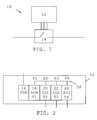
- One such system 10 is schematically shown in fig. 1 .
- an intelligent electronic device (IED) 12 is connected to a piece of local system equipment 14.
- This piece of local equipment 14 may also be considered as a process interface device because it is an interface to a process or a part of a process being controlled or monitored by the IED 12.
- This process is typically an electrical process, like an electrical power generation or transmission process or an electrical power supply process.
- the piece of local equipment may be a piece of equipment such as a circuit breaker or a transformer.
- the piece of local equipment 14 here has direct point-to-point connections to the IED 12. As an example there are here three such connections between the IED 12 and the piece of equipment 14.
- the IED 12 here typically performs control and/or protection in relation to the process and the piece of local system equipment using a protection and/or control function.
- the substation automation or distribution automation system may include several further intelligent electronic devices, HMIs (human Machine Interface) and substation controllers, which may be interconnected via a computer communication network. Theses devices could then communicate via such a computer communication network using the IEC 68150 communication protocol. However, the IED 12 according to the present invention is isolated from such devices and therefore they are not shown in fig. 1 .
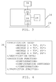
- Fig. 2 shows a block schematic of the IED 12 according to the present invention.
- the IED 12 is a modular device. It is modular in that it includes a number of hardware modules 16, 18, 20, 22 and 24 providing separate functionalities of the IED 12. These hardware modules may be replaceable and mechanically separable. This means that it is possible to vary the number and types of hardware modules in the IED 12.
- a first hardware module 16 which is a power supply module PSM that is connected to a power supply for receiving power for the whole IED 12 and for providing power to the rest of the modules in the IED. Power for the power supply module may here be received from the electrical process that the piece of equipment 14 is an interface to.
- a second module 18, which is a process control module PCM To this first module 16 there is connected a second module 18, which is a process control module PCM.
- the second module 18 is here connected to a third module 20, which is a first I/O module I01 that may be a first type of input module, for instance an input module handling analog input values.
- a fourth module 22 which is here a second I/O module IO2 that may be a second type of input module, like one handling digital input values.
- This fourth module 22 is here followed by a fifth module 24, which is here a third I/O module I03 that may be a first type of output module, for instance an output module handling digital output values.
- the I/O modules 20, 22 and 24 are provided for direct communication with local system equipment and therefore here have direct point-to-point connections with the pieces of local system equipment in order to provide and receive data from these pieces of equipment, like the piece of local system equipment in fig.
- I/O module 20 has one data connection
- the second I/O module 22 has one data connection
- the third I/O module 24 has one data connection that all lead to the piece of local equipment shown in fig. 1 .
- the IED may be connected to several such pieces of equipment using several data connections.
- the various modules are furthermore each provided with a respective type identifier T1, T2, T3 and T4.
- the second module 18 thus has a first type identifier T1, the third module 20 has a second type identifier T2, the fourth module 22 has a third type identifier T3 and the fifth module 24 has a fourth type identifier T4.
- a type identifier indicates what type of module it is, for instance type of I/O module or type of process control module perhaps together with brand or version indications. A type identifier is then stored internally in each such module.
- the various modules are furthermore interconnected or connected to each other by an inter-module data bus 26.
- the various modules are replaceable they can, when being mounted, be provided in any position on the bus 26.
- each connected module may also provide data, from which its position on the data bus 26 can be gathered.
- the second module 18 is here connected to a first position P1
- the third module 20 is here connected to a second position P2
- the fourth module 22 is here connected to a third position P3 while the fifth module 24 is here connected to a fourth position P4.
- the process control module 18 in the IED is shown in more detail in a block schematic provided in fig. 3 .
- the process control module 18 includes a control unit 28 providing processing functionality, for instance in relation to control of the piece of local system equipment and/or protection in relation to one or more system conditions.
- the control unit 28 thus handles at least one protection and/or control function.
- the control unit 28 is also connected to a verification data store 29 as well as to a first interface 30 and to a second interface 32.
- the first interface is an interface to a portable non-volatile data carrier 34, and may be provided as a USB port on the module 18, while the second interface 32 is a bus interface 46 to the inter-module bus 26.
- the data carrier 34 is thus not a part of the IED, but may be connected to it via the first interface 30.
- the data carrier in fig. 3 provides set-up data for the IED in the form of a configuration data file 36, the contents of which are schematically outlined in fig. 4 .
- the configuration data file 36 which may be provided as an XML file, includes two sections, a first section including verification data.
- the verification data here includes verification data regarding the type T1* and position P1* of a first module, regarding the type T2* and position P2* of a second module, regarding the type T3* and position P3* of a third module as well as regarding the type T4* and position P4* of a fourth module.
- the data may here be provided as type and position indicators.
- the second section relates to a protection and/or control function being provided by the process control module and here includes configuration settings to be applied in this function, which is here a protection function.
- the file may also include configuration settings concerning the functions of the other modules connected to the inter-module bus.
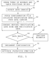
- the control unit 28 of the process control module 18 first senses what types of modules that are connected to the bus and their positions, step 38. This may be done through the use of a separate daisy chain connection between the various modules. At power up the first module connected to the power supply module 16 may receive an initiation signal on this separate connection. This module, which is here the process control module 18, then initiates itself and announces its functionality, including module type, on the inter-module bus 26. Since the module in question is the process control module 18 which keeps track of positions and types of modules, it then knows that it itself has the first position P1.
- the process control module 18 then forwards the initiation signal to the next module in the chain via the separate connection.
- the next module which is here the first I/O module 20, then initiates itself and announces its functionality, including module type, on the inter-module bus 26.
- the control unit 28 of the process control module 20 receives this announcement via the second interface 32, it then knows what type of module it was, but also the position because of the order in which initiation and announcement was made. It thus knows that the first I/O module 20 has the second position P2, since it is the second module performing initiation. Thereafter the first I/O module 20 forwards the initiating signal to the next module in the chain via the separate connection, which next module 22 then initiates itself and announces its functionality.
- initiation is performed sequentially and the control unit 28 of the process control module 18 senses the type and the positions until all modules have been initiated.
- the control unit 28 of the process control module 18 then stores this data as verification data in the verification data store 29. It furthermore stores the position data as position indicators and the type data as type indicators. It thus stores the type data T1 and position data P1 of itself, the type data T2 and position data P2 of the third module 20, the type data T3 and position data P3 of the fourth module 22 and the type data T4 and position data P4 of the fifth module 24 in the store 29.
- the type data T1 of the process control module 18 itself may already be stored together with the own position data P1 in this store 29, since it knows its own type and may always be the module having the first position, i.e. the module being closest to the power supply module 16.
- control unit 28 of the process control module 18 does include a function for protection and/or control of the process.
- this is a protection function only.
- the function is not yet configured and therefore also not activated.
- a field operator has to bring a portable non-volatile data carrier 34 including set-up data to the IED 12.
- a carrier can be a CD ROM disc or a memory stick.
- the control unit 28 detects that this has been done, step 40. Thereafter the control unit 28 obtains the set up data in the form of the configuration file 36 from the data carrier 34. It does this through fetching the configuration file 36 from the data carrier 34 via the first interface 30, step 42. As mentioned earlier the configuration file 36 includes verification data. The control unit 28 now goes on and compares this fetched verification data in the configuration file 36 with the own verification data that is stored in the verification data store 29, step 44.
- step 46 the control unit 28 indicates that there is a mismatch, step 48. This may be done through providing a sound or visual indication, for instance a certain color like red, which may be provided through a light emitting diode on the exterior of the IED. If however all verification data that was compared match, step 46, then the control unit 28 goes on and implements the configuration of the protective function, step 50. This may be followed by implementing configurations of the I/O modules 20, 22 and 24. For this reason the control unit 28 may transfer configuration settings to the respective I/O modules via the second interface 32 and the inter-module bus 26.
- control unit 28 goes on and activates the protective function, step 52.
- an activated protective function may be signaled through a sound or a visual indication, like a certain color, for instance green, which may also be provided through a light emitting diode.
- the field operator can configure the IED and at the same time verify that the installation is correct, i.e. verify that the IED includes the proper modules at their intended positions. This enhances the security in the system. This is furthermore done in a user friendly way.
- the field operator does not have to have any special skills. Through this way of providing configurations it is furthermore not possible to perform unauthorized configuration changes in the field. Since no expensive user interfaces are needed the cost of the IED can also be kept low.
- the field operator can also get a direct indication of if the installation is correct or not in a simple manner through a sound or light indication.
- the control unit of the process control module may be provided in the form of a processor with corresponding program memory including computer program code for performing its functionality, while the verification data store may be a memory like a RAM memory.
- the verification data on the carrier may include a device identifier or a code that is compared with a pre-stored device identifier or code. This further enhances the security in identifying the correct IED.
- the verification data stored in the verification data store If there is a difference between the verification data stored in the verification data store and the verification data that is fetched, it is furthermore possible to store data enabling identifying the differences on the data carrier.
- One way is to copy all the verification data provided in the verified data store to the data carrier. It is also possible to only copy the own verification data that differs. In this way the data carrier may be brought back to a system engineer, which may identity where the fault lies and perform corrective actions.
- the first interface is not limited to being provided on the process control module. It may for instance be provided on the inter-module bus. It is furthermore possible that the position data is not investigated, but only the types of modules. The way position data was sensed may furthermore be performed differently. Each module may be provided with position data in the form of type indicators and may automatically send them out on the inter-module bus at power up. Alternatively the process control unit may query the modules of this information. The position data can also be obtained through detecting the connections to the inter-module bus that the modules use. Position data may here be a part of the communication protocol used.
Landscapes
- Engineering & Computer Science (AREA)
- Computer Networks & Wireless Communication (AREA)
- Signal Processing (AREA)
- Emergency Protection Circuit Devices (AREA)
- Remote Monitoring And Control Of Power-Distribution Networks (AREA)
- Storage Device Security (AREA)
Claims (17)
- Dispositif électronique intelligent (12) prévu dans des systèmes d'automatisation de sous-station ou d'automatisation de distribution (10) et comprenant :- un bus inter-module (26)- une première interface (30) vers un support de données portable externe (34), et- un certain nombre de modules matériels (18, 20, 22, 24) reliés entre eux par l'intermédiaire dudit bus inter-module (26), lesdits modules mettant en oeuvre diverse fonctions du dispositif et comportant un module de commande de processus (18) pour gérer au moins une fonction de protection et/ou de commande,- ledit module de commande de processus (18) comportant- une deuxième interface (32) vers le bus inter-module (26), et- une unité de commande (28) disposée afin de- détecter, par l'intermédiaire de ladite deuxième interface (32), les types (T1, T2, T3, T4) de modules matériels reliés au bus inter-module, caractérisé en ce que l'unité de commande est en outre disposée afin- d'obtenir des données d'installation (36) à partir d'un support de données portable externe (34) relié à la première interface, lesdites données d'installation comportant des données de configuration ayant trait à une fonction de protection et/ou de commande mise en oeuvre par le module de commande de processus ainsi que des données de vérification, lesdites données de vérification obtenues comportant des données de type matériel (T1*, T2*, T3*, T4*) ayant trait aux modules dans le dispositif,- de comparer les données de vérification obtenues à des propres données de vérification, lesquelles propres données de vérification comportent des données concernant le type de matériel détecté, et- d'activer la fonction de protection et/ou de commande uniquement s'il existe une correspondance entre toutes les données de vérification en cours de comparaison.
- Dispositif (14) selon la revendication 1, dans lequel ledit nombre de modules matériels (18, 20, 22, 24) sont en train d'être reliés l'un à l'autre en différentes positions du bus inter-module (26), l'unité de commande du module de commande de processus est encore disposée afin de détecter, par l'intermédiaire de ladite deuxième interface (32), les positions (P1, P2, P3, P4) des modules matériels sur le bus inter-module, lesdites données de vérification obtenues comportent également des données de type position (P1*, P2*, P3*, P4*) ayant trait aux modules dans le dispositif et des propres données de vérification comportent des données concernant les positions détectées des modules matériels.
- Dispositif (14) selon la revendication 1 ou 2, dans lequel les données de vérification obtenues comportent un identifiant de dispositif et les propres données de vérification comportent un identifiant de dispositif mémorisé au préalable.
- Dispositif (12) selon toute revendication précédente, dans lequel l'unité de commande (28) est disposée afin de détecter le support de données en train d'être relié à la première interface et d'obtenir les types de données d'installation sur la base de cette détection.
- Dispositif (12) selon toute revendication précédente, dans lequel l'unité de commande (28) est en outre disposée afin de mettre en oeuvre la configuration de la fonction de protection et/ou de commande s'il existe une correspondance entre toutes les données de vérification en cours de comparaison.
- Dispositif (12) selon toute revendication précédente, dans lequel l'unité de commande (28) est en outre disposée afin d'indiquer qu'il y a une disparité si toutes données de vérification en cours de comparaison ne correspondent pas.
- Dispositif (12) selon toute revendication précédente, dans lequel l'unité de commande (28) est en outre disposée afin de mémoriser des propres données de vérification sur le support de données portable si toutes données de vérification en cours de comparaison ne correspondent pas.
- Dispositif (12) selon toute revendication précédente, comprenant en outre un module d'alimentation (16) fournissant de la puissance aux autres modules du dispositif.
- Dispositif (12) selon toute revendication précédente, dans lequel l'unité de commande est en outre disposée afin de réaliser ladite détection à l'enclenchement du dispositif.
- Procédé pour activer une fonction dans un dispositif électronique intelligent (12) prévu dans un système d'automatisation de sous-station ou d'automatisation de distribution (10), le dispositif électronique intelligent comprenant un certain nombre de modules matériels (18, 20, 22, 24) reliés l'un à l'autre par l'intermédiaire d'un bus inter-module (26), lesdits modules mettant en oeuvre diverses fonctions du dispositif et comportant un module de commande de processus (18) afin de gérer au moins une fonction de protection et/ou de commande du dispositif, le procédé comprenant l'étape consistant à :- détecter (38) les types (T1, T2, T3, T4) des modules matériels reliés au bus inter-module (26),
caractérisé en ce que le procédé comprend les étapes supplémentaires consistant :- à obtenir (42) des données d'installation (36) à partir d'un support de données portable externe (34), lesdites données d'installation comportant des données de configuration ayant trait à une fonction de protection et/ou de commande mise en oeuvre par le module de commande de processus, ainsi que des données de vérification, lesdites données de vérification obtenues comportant des données de type matériel (T1*, T2*, T3*, T4*) ayant trait aux modules dans le dispositif,- à comparer (44) les données de vérification obtenues à des propres données de vérification, lesquelles propres données de vérification comportent des données concernant le type de matériel détecté, et- à activer (45) la fonction de protection et/ou de commande uniquement s'il existe une correspondance (46) entre toutes les données de vérification en cours de comparaison. - Procédé selon la revendication 10, dans lequel ledit nombre de modules matériels (18, 20, 22, 24) sont reliés entre eux en différentes positions dudit bus inter-module (26), l'étape de détection comprend en outre la détection des positions (P1, P2, P3, P4) des modules matériels sur le bus inter-module, lesdites données de vérification obtenues comportent des données de type position (P1*, P2*, P3*, P4*) ayant trait aux modules dans le dispositif et des propres données de vérification comportent des données concernant les positions détectées des modules matériels.
- Procédé selon la revendication 10 ou 11, dans lequel les données de vérification obtenues comportent un identifiant de dispositif et les propres données de vérification comportent un identifiant de dispositif mémorisé au préalable.
- Procédé selon l'une quelconque des revendications 10 à 12, comprenant en outre l'étape (40) consistant à détecter le support de données (34) relié au dispositif électronique intelligent (12) et à réaliser l'étape consistant à obtenir lesdites données d'installation sur la base de cette détection.
- Procédé selon l'une quelconque des revendications 10 à 13, comprenant en outre l'étape (50) consistant à mettre en oeuvre la configuration de la fonction de protection et/ou de commande s'il existe une correspondance (46) entre toutes les données de vérification en cours de comparaison.
- Procédé selon l'une quelconque des revendications 10 à 14, comprenant en outre l'étape (48) consistant à indiquer qu'il y a une disparité si toutes données de vérification en cours de comparaison ne correspondent pas.
- Procédé selon l'une quelconque des revendications 10 à 15, comprenant en outre l'étape consistant à mémoriser des propres données de vérification sur le support de données portable (34) si toutes données de vérification en cours de comparaison ne correspondent pas.
- Procédé selon l'une quelconque des revendications 10 à 16, dans lequel l'étape de détection se réalise à l'enclenchement du dispositif.
Priority Applications (5)
| Application Number | Priority Date | Filing Date | Title |
|---|---|---|---|
| EP08159063A EP2139162B1 (fr) | 2008-06-26 | 2008-06-26 | Configuration d'un dispositif électronique intelligent |
| AT08159063T ATE534211T1 (de) | 2008-06-26 | 2008-06-26 | Konfigurierung eines intelligenten elektronischen geräts |
| CN2009801247278A CN102077512B (zh) | 2008-06-26 | 2009-06-26 | 对智能电子设备的配置 |
| PCT/EP2009/058021 WO2009156497A1 (fr) | 2008-06-26 | 2009-06-26 | Configuration d’un dispositif électronique intelligent |
| US12/977,914 US8051215B2 (en) | 2008-06-26 | 2010-12-23 | Configuring of an intelligent electronic device |
Applications Claiming Priority (1)
| Application Number | Priority Date | Filing Date | Title |
|---|---|---|---|
| EP08159063A EP2139162B1 (fr) | 2008-06-26 | 2008-06-26 | Configuration d'un dispositif électronique intelligent |
Publications (2)
| Publication Number | Publication Date |
|---|---|
| EP2139162A1 EP2139162A1 (fr) | 2009-12-30 |
| EP2139162B1 true EP2139162B1 (fr) | 2011-11-16 |
Family
ID=39761023
Family Applications (1)
| Application Number | Title | Priority Date | Filing Date |
|---|---|---|---|
| EP08159063A Active EP2139162B1 (fr) | 2008-06-26 | 2008-06-26 | Configuration d'un dispositif électronique intelligent |
Country Status (5)
| Country | Link |
|---|---|
| US (1) | US8051215B2 (fr) |
| EP (1) | EP2139162B1 (fr) |
| CN (1) | CN102077512B (fr) |
| AT (1) | ATE534211T1 (fr) |
| WO (1) | WO2009156497A1 (fr) |
Families Citing this family (8)
| Publication number | Priority date | Publication date | Assignee | Title |
|---|---|---|---|---|
| EP1850109A1 (fr) * | 2006-04-24 | 2007-10-31 | ABB Research Ltd | Vérification de configuration dans un dispositif électronique intelligent |
| EP2138913B1 (fr) * | 2008-06-25 | 2011-10-26 | ABB Research Ltd. | Dispositif électronique intelligent flexible |
| EP2761437A4 (fr) * | 2011-09-30 | 2015-11-11 | Nokia Technologies Oy | Procédé et appareil pour faciliter les communications entre widgets |
| CN102520660A (zh) * | 2011-12-13 | 2012-06-27 | 深圳市合信自动化技术有限公司 | 可编程逻辑控制器及其系统、传输工程的方法 |
| EP2608450B1 (fr) * | 2011-12-20 | 2016-11-30 | ABB Research Ltd. | Validation d'un réseau de communication d'un système d'automatisation et de contrôle industriel |
| US9423822B1 (en) * | 2013-03-14 | 2016-08-23 | The Mathworks, Inc. | Automatic data acquisition subsystem synchronization and sample rate arbitration |
| CN103324456B (zh) * | 2013-06-06 | 2016-03-02 | 京东方科技集团股份有限公司 | 一种显示模式的设置方法及显示模式配置系统 |
| US10288646B2 (en) | 2015-02-26 | 2019-05-14 | Potential Labs, Llc | Determining energy usage of a residence based on current monitoring |
Family Cites Families (17)
| Publication number | Priority date | Publication date | Assignee | Title |
|---|---|---|---|---|
| US5323393A (en) * | 1992-11-18 | 1994-06-21 | Canon Information Systems, Inc. | Method and apparatus for obtaining and for controlling the status of a networked peripheral |
| US20020092018A1 (en) | 2000-11-29 | 2002-07-11 | Shobana Biederman | Reusing the same hardware platform by loading different application software from a memory stick |
| US6871150B2 (en) | 2001-02-23 | 2005-03-22 | Power Measurement Ltd. | Expandable intelligent electronic device |
| US7415725B2 (en) * | 2002-08-29 | 2008-08-19 | Power Measurement Ltd. | Multi-function intelligent electronic device with secure access |
| ATE405035T1 (de) * | 2002-11-15 | 2008-08-15 | Abb Research Ltd | Konfigurationssystem für netzwerkgeräte und verfahren zum rekonfigurieren von geräten |
| US6842794B2 (en) | 2003-05-27 | 2005-01-11 | Inventec Corporation | Method for starting a data processing system via a flash memory device |
| US7370248B2 (en) * | 2003-11-07 | 2008-05-06 | Hewlett-Packard Development Company, L.P. | In-service raid mirror reconfiguring |
| DE102004062967A1 (de) * | 2004-12-28 | 2006-07-06 | Röllgen, Bernd | Verfahren zum Konfigurieren von Geräten in einem Computernetzwerk durch ein Computerprogramm |
| US20060269066A1 (en) * | 2005-05-06 | 2006-11-30 | Schweitzer Engineering Laboratories, Inc. | System and method for converting serial data into secure data packets configured for wireless transmission in a power system |
| WO2007036178A1 (fr) | 2005-09-29 | 2007-04-05 | Siemens Aktiengesellschaft | Procede de realisation d'une fonction protegee d'un appareil de champ electrique |
| US20070106764A1 (en) | 2005-11-08 | 2007-05-10 | Carl Mansfield | System and method for device configuration using a portable flash memory storage device with an infrared transmitter |
| EP1850109A1 (fr) * | 2006-04-24 | 2007-10-31 | ABB Research Ltd | Vérification de configuration dans un dispositif électronique intelligent |
| PL1850142T3 (pl) * | 2006-04-24 | 2009-06-30 | Abb Research Ltd | Testowanie poziomu systemowego dla systemów automatyzacji stacji elektroenergetycznych |
| EP2186251B1 (fr) * | 2007-08-28 | 2019-10-09 | ABB Schweiz AG | Sécurité de communication en temps réel pour des réseaux d'automatisation |
| CN101836122B (zh) * | 2007-10-25 | 2014-12-24 | Abb研究有限公司 | 操作变电站自动化系统 |
| EP2138913B1 (fr) * | 2008-06-25 | 2011-10-26 | ABB Research Ltd. | Dispositif électronique intelligent flexible |
| US20110161468A1 (en) * | 2009-12-31 | 2011-06-30 | Schneider Electric USA, Inc. | Method and system for cascading peer-to-peer configuration of large systems of ieds |
-
2008
- 2008-06-26 EP EP08159063A patent/EP2139162B1/fr active Active
- 2008-06-26 AT AT08159063T patent/ATE534211T1/de active
-
2009
- 2009-06-26 WO PCT/EP2009/058021 patent/WO2009156497A1/fr not_active Ceased
- 2009-06-26 CN CN2009801247278A patent/CN102077512B/zh active Active
-
2010
- 2010-12-23 US US12/977,914 patent/US8051215B2/en active Active
Also Published As
| Publication number | Publication date |
|---|---|
| US8051215B2 (en) | 2011-11-01 |
| ATE534211T1 (de) | 2011-12-15 |
| EP2139162A1 (fr) | 2009-12-30 |
| CN102077512B (zh) | 2013-07-03 |
| CN102077512A (zh) | 2011-05-25 |
| WO2009156497A1 (fr) | 2009-12-30 |
| US20110138083A1 (en) | 2011-06-09 |
Similar Documents
| Publication | Publication Date | Title |
|---|---|---|
| US8051215B2 (en) | Configuring of an intelligent electronic device | |
| CN112136369B (zh) | 一种电源线设备 | |
| US6784802B1 (en) | Real time monitoring of cable patch panel | |
| US9047279B1 (en) | Methods and systems for using two-dimensional matrix codes associated with panel component and equipment information and quality control | |
| US10503680B2 (en) | Method for operating an automation device | |
| EP2912478B1 (fr) | Méthode et appareil d'étalonnage de prises ca intelligentes | |
| US8341304B2 (en) | Flexible intelligent electronic device | |
| CN106020136B (zh) | 用于定义槽位地址的方法及系统 | |
| CN104620447B (zh) | 用于形成插接连接的插接件 | |
| CN1953278A (zh) | 电插头和用于分散保存传感器参数的方法 | |
| CN101978280A (zh) | 电弧故障根本原因查找系统和方法 | |
| US11128527B2 (en) | Installation support device and method for installation process support for an automation system | |
| EP3989395B1 (fr) | Procédé, dispositif et programme informatique pour configurer un dispositif électronique intelligent | |
| WO2009129122A1 (fr) | Procédé et appareil permettant de concevoir des configurations dispositif à dispositif pouvant être utilisées dans un système électrique | |
| CN112380066B (zh) | 一种基于国产平台的服务器维护调试装置及服务器 | |
| WO2010035137A2 (fr) | Collecte et transmission de données sécurisées | |
| CN109901551A (zh) | 工控设备的信息获取方法、信息获取装置及终端设备 | |
| US20080250236A1 (en) | Configuration Appliance and Method for Configuration of Electrical Appliances | |
| US9032221B2 (en) | Apparatus for logging a configuration of a microprocessor system and method for logging a configuration of a microprocessor system | |
| CN207115480U (zh) | 智能货架系统、仓储管理系统及货物陈列管理系统 | |
| JP2015149807A (ja) | ヒューマンインターフェース端末およびディジタル形保護制御装置 | |
| HK1059134B (en) | Cradle for more than one search-type karaoke-song-selectable remote controllers |
Legal Events
| Date | Code | Title | Description |
|---|---|---|---|
| PUAI | Public reference made under article 153(3) epc to a published international application that has entered the european phase |
Free format text: ORIGINAL CODE: 0009012 |
|
| 17P | Request for examination filed |
Effective date: 20080626 |
|
| AK | Designated contracting states |
Kind code of ref document: A1 Designated state(s): AT BE BG CH CY CZ DE DK EE ES FI FR GB GR HR HU IE IS IT LI LT LU LV MC MT NL NO PL PT RO SE SI SK TR |
|
| AX | Request for extension of the european patent |
Extension state: AL BA MK RS |
|
| 17Q | First examination report despatched |
Effective date: 20100216 |
|
| AKX | Designation fees paid |
Designated state(s): AT BE BG CH CY CZ DE DK EE ES FI FR GB GR HR HU IE IS IT LI LT LU LV MC MT NL NO PL PT RO SE SI SK TR |
|
| GRAJ | Information related to disapproval of communication of intention to grant by the applicant or resumption of examination proceedings by the epo deleted |
Free format text: ORIGINAL CODE: EPIDOSDIGR1 |
|
| GRAP | Despatch of communication of intention to grant a patent |
Free format text: ORIGINAL CODE: EPIDOSNIGR1 |
|
| GRAP | Despatch of communication of intention to grant a patent |
Free format text: ORIGINAL CODE: EPIDOSNIGR1 |
|
| RAP1 | Party data changed (applicant data changed or rights of an application transferred) |
Owner name: ABB RESEARCH LTD. |
|
| GRAS | Grant fee paid |
Free format text: ORIGINAL CODE: EPIDOSNIGR3 |
|
| GRAA | (expected) grant |
Free format text: ORIGINAL CODE: 0009210 |
|
| AK | Designated contracting states |
Kind code of ref document: B1 Designated state(s): AT BE BG CH CY CZ DE DK EE ES FI FR GB GR HR HU IE IS IT LI LT LU LV MC MT NL NO PL PT RO SE SI SK TR |
|
| REG | Reference to a national code |
Ref country code: GB Ref legal event code: FG4D |
|
| REG | Reference to a national code |
Ref country code: CH Ref legal event code: EP |
|
| REG | Reference to a national code |
Ref country code: IE Ref legal event code: FG4D |
|
| REG | Reference to a national code |
Ref country code: DE Ref legal event code: R096 Ref document number: 602008011376 Country of ref document: DE Effective date: 20120126 |
|
| REG | Reference to a national code |
Ref country code: NL Ref legal event code: VDEP Effective date: 20111116 |
|
| LTIE | Lt: invalidation of european patent or patent extension |
Effective date: 20111116 |
|
| PG25 | Lapsed in a contracting state [announced via postgrant information from national office to epo] |
Ref country code: NO Free format text: LAPSE BECAUSE OF FAILURE TO SUBMIT A TRANSLATION OF THE DESCRIPTION OR TO PAY THE FEE WITHIN THE PRESCRIBED TIME-LIMIT Effective date: 20120216 Ref country code: LT Free format text: LAPSE BECAUSE OF FAILURE TO SUBMIT A TRANSLATION OF THE DESCRIPTION OR TO PAY THE FEE WITHIN THE PRESCRIBED TIME-LIMIT Effective date: 20111116 Ref country code: IS Free format text: LAPSE BECAUSE OF FAILURE TO SUBMIT A TRANSLATION OF THE DESCRIPTION OR TO PAY THE FEE WITHIN THE PRESCRIBED TIME-LIMIT Effective date: 20120316 |
|
| PG25 | Lapsed in a contracting state [announced via postgrant information from national office to epo] |
Ref country code: NL Free format text: LAPSE BECAUSE OF FAILURE TO SUBMIT A TRANSLATION OF THE DESCRIPTION OR TO PAY THE FEE WITHIN THE PRESCRIBED TIME-LIMIT Effective date: 20111116 Ref country code: PL Free format text: LAPSE BECAUSE OF FAILURE TO SUBMIT A TRANSLATION OF THE DESCRIPTION OR TO PAY THE FEE WITHIN THE PRESCRIBED TIME-LIMIT Effective date: 20111116 Ref country code: PT Free format text: LAPSE BECAUSE OF FAILURE TO SUBMIT A TRANSLATION OF THE DESCRIPTION OR TO PAY THE FEE WITHIN THE PRESCRIBED TIME-LIMIT Effective date: 20120316 Ref country code: SI Free format text: LAPSE BECAUSE OF FAILURE TO SUBMIT A TRANSLATION OF THE DESCRIPTION OR TO PAY THE FEE WITHIN THE PRESCRIBED TIME-LIMIT Effective date: 20111116 Ref country code: HR Free format text: LAPSE BECAUSE OF FAILURE TO SUBMIT A TRANSLATION OF THE DESCRIPTION OR TO PAY THE FEE WITHIN THE PRESCRIBED TIME-LIMIT Effective date: 20111116 Ref country code: SE Free format text: LAPSE BECAUSE OF FAILURE TO SUBMIT A TRANSLATION OF THE DESCRIPTION OR TO PAY THE FEE WITHIN THE PRESCRIBED TIME-LIMIT Effective date: 20111116 Ref country code: LV Free format text: LAPSE BECAUSE OF FAILURE TO SUBMIT A TRANSLATION OF THE DESCRIPTION OR TO PAY THE FEE WITHIN THE PRESCRIBED TIME-LIMIT Effective date: 20111116 Ref country code: BE Free format text: LAPSE BECAUSE OF FAILURE TO SUBMIT A TRANSLATION OF THE DESCRIPTION OR TO PAY THE FEE WITHIN THE PRESCRIBED TIME-LIMIT Effective date: 20111116 Ref country code: GR Free format text: LAPSE BECAUSE OF FAILURE TO SUBMIT A TRANSLATION OF THE DESCRIPTION OR TO PAY THE FEE WITHIN THE PRESCRIBED TIME-LIMIT Effective date: 20120217 |
|
| PG25 | Lapsed in a contracting state [announced via postgrant information from national office to epo] |
Ref country code: CY Free format text: LAPSE BECAUSE OF FAILURE TO SUBMIT A TRANSLATION OF THE DESCRIPTION OR TO PAY THE FEE WITHIN THE PRESCRIBED TIME-LIMIT Effective date: 20111116 |
|
| PG25 | Lapsed in a contracting state [announced via postgrant information from national office to epo] |
Ref country code: CZ Free format text: LAPSE BECAUSE OF FAILURE TO SUBMIT A TRANSLATION OF THE DESCRIPTION OR TO PAY THE FEE WITHIN THE PRESCRIBED TIME-LIMIT Effective date: 20111116 Ref country code: DK Free format text: LAPSE BECAUSE OF FAILURE TO SUBMIT A TRANSLATION OF THE DESCRIPTION OR TO PAY THE FEE WITHIN THE PRESCRIBED TIME-LIMIT Effective date: 20111116 Ref country code: EE Free format text: LAPSE BECAUSE OF FAILURE TO SUBMIT A TRANSLATION OF THE DESCRIPTION OR TO PAY THE FEE WITHIN THE PRESCRIBED TIME-LIMIT Effective date: 20111116 Ref country code: SK Free format text: LAPSE BECAUSE OF FAILURE TO SUBMIT A TRANSLATION OF THE DESCRIPTION OR TO PAY THE FEE WITHIN THE PRESCRIBED TIME-LIMIT Effective date: 20111116 Ref country code: BG Free format text: LAPSE BECAUSE OF FAILURE TO SUBMIT A TRANSLATION OF THE DESCRIPTION OR TO PAY THE FEE WITHIN THE PRESCRIBED TIME-LIMIT Effective date: 20120216 |
|
| PG25 | Lapsed in a contracting state [announced via postgrant information from national office to epo] |
Ref country code: RO Free format text: LAPSE BECAUSE OF FAILURE TO SUBMIT A TRANSLATION OF THE DESCRIPTION OR TO PAY THE FEE WITHIN THE PRESCRIBED TIME-LIMIT Effective date: 20111116 |
|
| REG | Reference to a national code |
Ref country code: AT Ref legal event code: MK05 Ref document number: 534211 Country of ref document: AT Kind code of ref document: T Effective date: 20111116 |
|
| PLBE | No opposition filed within time limit |
Free format text: ORIGINAL CODE: 0009261 |
|
| STAA | Information on the status of an ep patent application or granted ep patent |
Free format text: STATUS: NO OPPOSITION FILED WITHIN TIME LIMIT |
|
| 26N | No opposition filed |
Effective date: 20120817 |
|
| REG | Reference to a national code |
Ref country code: DE Ref legal event code: R097 Ref document number: 602008011376 Country of ref document: DE Effective date: 20120817 |
|
| PG25 | Lapsed in a contracting state [announced via postgrant information from national office to epo] |
Ref country code: MC Free format text: LAPSE BECAUSE OF NON-PAYMENT OF DUE FEES Effective date: 20120630 Ref country code: AT Free format text: LAPSE BECAUSE OF FAILURE TO SUBMIT A TRANSLATION OF THE DESCRIPTION OR TO PAY THE FEE WITHIN THE PRESCRIBED TIME-LIMIT Effective date: 20111116 |
|
| REG | Reference to a national code |
Ref country code: CH Ref legal event code: PL |
|
| REG | Reference to a national code |
Ref country code: CH Ref legal event code: PL |
|
| REG | Reference to a national code |
Ref country code: IE Ref legal event code: MM4A |
|
| PG25 | Lapsed in a contracting state [announced via postgrant information from national office to epo] |
Ref country code: IE Free format text: LAPSE BECAUSE OF NON-PAYMENT OF DUE FEES Effective date: 20120626 Ref country code: LI Free format text: LAPSE BECAUSE OF NON-PAYMENT OF DUE FEES Effective date: 20120630 Ref country code: CH Free format text: LAPSE BECAUSE OF NON-PAYMENT OF DUE FEES Effective date: 20120630 Ref country code: ES Free format text: LAPSE BECAUSE OF FAILURE TO SUBMIT A TRANSLATION OF THE DESCRIPTION OR TO PAY THE FEE WITHIN THE PRESCRIBED TIME-LIMIT Effective date: 20120227 |
|
| PG25 | Lapsed in a contracting state [announced via postgrant information from national office to epo] |
Ref country code: MT Free format text: LAPSE BECAUSE OF FAILURE TO SUBMIT A TRANSLATION OF THE DESCRIPTION OR TO PAY THE FEE WITHIN THE PRESCRIBED TIME-LIMIT Effective date: 20111116 |
|
| PG25 | Lapsed in a contracting state [announced via postgrant information from national office to epo] |
Ref country code: TR Free format text: LAPSE BECAUSE OF FAILURE TO SUBMIT A TRANSLATION OF THE DESCRIPTION OR TO PAY THE FEE WITHIN THE PRESCRIBED TIME-LIMIT Effective date: 20111116 |
|
| PG25 | Lapsed in a contracting state [announced via postgrant information from national office to epo] |
Ref country code: LU Free format text: LAPSE BECAUSE OF NON-PAYMENT OF DUE FEES Effective date: 20120626 |
|
| PG25 | Lapsed in a contracting state [announced via postgrant information from national office to epo] |
Ref country code: HU Free format text: LAPSE BECAUSE OF FAILURE TO SUBMIT A TRANSLATION OF THE DESCRIPTION OR TO PAY THE FEE WITHIN THE PRESCRIBED TIME-LIMIT Effective date: 20080626 |
|
| REG | Reference to a national code |
Ref country code: FR Ref legal event code: PLFP Year of fee payment: 9 |
|
| REG | Reference to a national code |
Ref country code: FR Ref legal event code: PLFP Year of fee payment: 10 |
|
| REG | Reference to a national code |
Ref country code: FR Ref legal event code: PLFP Year of fee payment: 11 |
|
| REG | Reference to a national code |
Ref country code: DE Ref legal event code: R081 Ref document number: 602008011376 Country of ref document: DE Owner name: ABB SCHWEIZ AG, CH Free format text: FORMER OWNER: ABB RESEARCH LTD., ZUERICH, CH |
|
| REG | Reference to a national code |
Ref country code: GB Ref legal event code: 732E Free format text: REGISTERED BETWEEN 20200206 AND 20200212 |
|
| REG | Reference to a national code |
Ref country code: DE Ref legal event code: R079 Ref document number: 602008011376 Country of ref document: DE Free format text: PREVIOUS MAIN CLASS: H04L0012240000 Ipc: H04L0041000000 |
|
| PGFP | Annual fee paid to national office [announced via postgrant information from national office to epo] |
Ref country code: FI Payment date: 20250627 Year of fee payment: 18 |
|
| PGFP | Annual fee paid to national office [announced via postgrant information from national office to epo] |
Ref country code: DE Payment date: 20250618 Year of fee payment: 18 |
|
| PGFP | Annual fee paid to national office [announced via postgrant information from national office to epo] |
Ref country code: GB Payment date: 20250618 Year of fee payment: 18 |
|
| PGFP | Annual fee paid to national office [announced via postgrant information from national office to epo] |
Ref country code: FR Payment date: 20250624 Year of fee payment: 18 |
|
| PGFP | Annual fee paid to national office [announced via postgrant information from national office to epo] |
Ref country code: IT Payment date: 20250624 Year of fee payment: 18 |