EP2139072A2 - Wire grounding assembly - Google Patents
Wire grounding assembly Download PDFInfo
- Publication number
- EP2139072A2 EP2139072A2 EP09163480A EP09163480A EP2139072A2 EP 2139072 A2 EP2139072 A2 EP 2139072A2 EP 09163480 A EP09163480 A EP 09163480A EP 09163480 A EP09163480 A EP 09163480A EP 2139072 A2 EP2139072 A2 EP 2139072A2
- Authority
- EP
- European Patent Office
- Prior art keywords
- threaded shaft
- bidirectional connector
- wire
- grounding assembly
- torque
- Prior art date
- Legal status (The legal status is an assumption and is not a legal conclusion. Google has not performed a legal analysis and makes no representation as to the accuracy of the status listed.)
- Granted
Links
Images


Classifications
-
- H—ELECTRICITY
- H01—ELECTRIC ELEMENTS
- H01R—ELECTRICALLY-CONDUCTIVE CONNECTIONS; STRUCTURAL ASSOCIATIONS OF A PLURALITY OF MUTUALLY-INSULATED ELECTRICAL CONNECTING ELEMENTS; COUPLING DEVICES; CURRENT COLLECTORS
- H01R4/00—Electrically-conductive connections between two or more conductive members in direct contact, i.e. touching one another; Means for effecting or maintaining such contact; Electrically-conductive connections having two or more spaced connecting locations for conductors and using contact members penetrating insulation
- H01R4/58—Electrically-conductive connections between two or more conductive members in direct contact, i.e. touching one another; Means for effecting or maintaining such contact; Electrically-conductive connections having two or more spaced connecting locations for conductors and using contact members penetrating insulation characterised by the form or material of the contacting members
- H01R4/64—Connections between or with conductive parts having primarily a non-electric function, e.g. frame, casing, rail
- H01R4/646—Connections between or with conductive parts having primarily a non-electric function, e.g. frame, casing, rail for cables or flexible cylindrical bodies
-
- H—ELECTRICITY
- H01—ELECTRIC ELEMENTS
- H01R—ELECTRICALLY-CONDUCTIVE CONNECTIONS; STRUCTURAL ASSOCIATIONS OF A PLURALITY OF MUTUALLY-INSULATED ELECTRICAL CONNECTING ELEMENTS; COUPLING DEVICES; CURRENT COLLECTORS
- H01R4/00—Electrically-conductive connections between two or more conductive members in direct contact, i.e. touching one another; Means for effecting or maintaining such contact; Electrically-conductive connections having two or more spaced connecting locations for conductors and using contact members penetrating insulation
- H01R4/28—Clamped connections, spring connections
- H01R4/30—Clamped connections, spring connections utilising a screw or nut clamping member
- H01R4/32—Conductive members located in slot or hole in screw
-
- H—ELECTRICITY
- H01—ELECTRIC ELEMENTS
- H01R—ELECTRICALLY-CONDUCTIVE CONNECTIONS; STRUCTURAL ASSOCIATIONS OF A PLURALITY OF MUTUALLY-INSULATED ELECTRICAL CONNECTING ELEMENTS; COUPLING DEVICES; CURRENT COLLECTORS
- H01R4/00—Electrically-conductive connections between two or more conductive members in direct contact, i.e. touching one another; Means for effecting or maintaining such contact; Electrically-conductive connections having two or more spaced connecting locations for conductors and using contact members penetrating insulation
- H01R4/58—Electrically-conductive connections between two or more conductive members in direct contact, i.e. touching one another; Means for effecting or maintaining such contact; Electrically-conductive connections having two or more spaced connecting locations for conductors and using contact members penetrating insulation characterised by the form or material of the contacting members
- H01R4/66—Connections with the terrestrial mass, e.g. earth plate, earth pin
Definitions
- the present invention is directed to a wire grounding assembly and, more specifically, to a wire grounding assembly that is especially suitable for use in grounding a photovoltaic module having an anodized aluminum frame.
- PV Photovoltaic
- PV modules or arrays produce electricity from solar energy. Electrical power produced by PV modules reduces reliance on electricity generated using non-renewable resources (e . g ., fossil fuels), resulting in significant environmental benefits. For the purpose of reducing or eliminating shock and fire hazards, the National Electric Code (NEC) and UL Standard 1703 require the electrical grounding of PV modules.
- NEC National Electric Code
- An effective connection to ground reduces the susceptibility of a PV module to damage by lightning, reduces electrostatic buildup (which can damage a PV module), and reduces the risk of harm to personnel who service and repair PV modules. In effect, a connection to ground drains away any excess buildup of electrical charge.
- a PV module is usually contained in an anodized aluminum frame, the surface of which is non-conductive. Generally speaking, it is the frame of the PV module that serves as the ground, which renders it challenging for personnel to efficiently install a reliable ground path between the PV module and its frame. While wire grounding assemblies are known, including devices that are used in establishing grounds, there is no known wire grounding assembly that is especially suitable for grounding a PV module in this manner.
- the problem to be solved is a need for a wire grounding assembly that enables personnel to efficiently install a reliable ground path between a PV module and its frame.
- the solution is provided by a wire grounding assembly.
- This assembly includes a unitary bidirectional connector having a torque-receiving portion that is radially oriented about the major axis of the unitary bidirectional connector.
- the torque-receiving portion has a first radial surface and an opposing second radial surface.
- the unitary bidirectional connector has a first threaded shaft and a second threaded shaft. The first threaded shaft projects from the first radial surface, and the second threaded shaft projects from the second radial surface.
- the first threaded shaft and the second threaded shaft are aligned such that their respective major axes coincide with the major axis of the unitary bidirectional connector.
- the first threaded shaft has an axial ground wire slot configured to receive a ground wire therein, and the second threaded shaft has a base.
- the unitary bidirectional connector also has an annular sharp projection that projects beyond a plane of the second radial surface, encircling the base of the second threaded shaft.
- the annular sharp projection is configured to penetrate a non-conductive surface of a ground upon application of sufficient torque to the torque-receiving portion.
- FIG. 1 is an exploded top view, in perspective, of an exemplary embodiment of the disclosed wire grounding assembly.
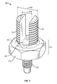
- FIG. 2 is an enlarged top view, in perspective, of a component ( i . e ., unitary bidirectional connector) of the exemplary embodiment shown in FIG. 1 .
- FIG. 3 is an exploded bottom view, in perspective, of the exemplary embodiment shown in FIG. 1 .
- FIG. 4 is an enlarged bottom view, in perspective, of the unitary bidirectional connector shown in FIG. 2 .
- FIG. 5 is a section view, in perspective, of the unitary bidirectional connector taken along line 5-5 of FIG. 4 .
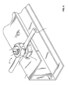
- FIG. 6 is a perspective view of the exemplary embodiment of the disclosed wire grounding assembly shown in FIG. 1 installed on the frame of a PV module.
- FIG. 1 is an exploded top view, in perspective, of an exemplary embodiment 10 of the wire grounding assembly of the present invention.
- Embodiment 10 includes a unitary bidirectional connector 20 having a first threaded shaft 30, a second threaded shaft 50, and a torque-receiving portion 70.
- First threaded shaft 30 and second threaded shaft 50 are aligned such that their respective major axes coincide with the major axis 100 of unitary bidirectional connector 20.
- First threaded shaft 30 is slotted along major axis 100, defining a ground wire slot 60 for receiving a ground wire.
- Torque-receiving portion 70 is radially oriented about major axis 100 and has a first radial surface 80 and an opposing second radial surface (see FIG.
- First threaded shaft 30 projects from first radial surface 80, and second threaded shaft 50 projects from second radial surface 90.
- the torque-receiving portion 70 has a peripheral surface 110 that is hexagonal, as shown in FIG. 1 . This feature allows personnel to apply torque to bidirectional connector 20 using a wrench, facilitating installation of the wire grounding assembly (see FIG. 6 ).
- Embodiment 10 of the wire grounding assembly includes first nut 120, which is dimensioned to engage first threaded shaft 30. Upon application of sufficient torque, first nut 120 will cooperate with unitary bidirectional connector 20 to secure via compression any ground wire of appropriate diameter present in ground wire slot 60. In a preferred embodiment, ground wire slot 60 is dimensioned to receive therein a ground wire. As shown in FIG. 1 , first nut 120 is hexagonal. Such a shape is preferred, allowing personnel to apply torque to first nut 120 using a wrench, thereby facilitating installation of the wire grounding assembly.
- Embodiment 10 also includes second nut 130, which is dimensioned to engage second threaded shaft 50.
- the frame 140 (see FIG. 6 ) of a PV module usually includes apertures 150 (see FIG. 6 ).
- Second threaded shaft 50 is dimensioned to engage aperture 150.
- Second nut 130 cooperates with second threaded shaft 50 of unitary bidirectional connector 20 to secure embodiment 10 to frame 140.
- second nut 130 is hexagonal, allowing personnel to apply torque to second nut 130 using a wrench.
- Second nut 130 optionally includes attached free-spinning washer 132.
- a nut is commonly referred to as a KEPS nut, K-nut, or washer nut.
- attached free-spinning washer 132 is a star-type lock washer, which has a serrated surface 134 capable of penetrating the (non-conductive) anodized surface of frame 140, to aid in ensuring proper grounding.
- another washer type e . g ., conical washer, flat washer may be substituted.
- FIG. 2 which is an enlarged top perspective view of unitary bidirectional connector 20, shows diameter 136, which represents the diameter of first threaded shaft 30, and slot width 138, which represents the width of ground wire slot 60.
- the pull-out test e . g ., 6 AWG (American Wire Gauge
- Unitary bidirectional connector 20 is preferably made from an electrically-conductive material that is corrosion resistant (e . g ., stainless steel). Such materials have variations in strength. Assuming slot width 138 is constant, diameter 136 of first threaded shaft 30 will vary inversely with the strength of the selected electrically-conductive material. In other words, a weaker material will generally require that diameter 136 be greater. Conversely, diameter 136 may be decreased when stronger materials are used.
- an electrically-conductive material that is corrosion resistant (e . g ., stainless steel). Such materials have variations in strength. Assuming slot width 138 is constant, diameter 136 of first threaded shaft 30 will vary inversely with the strength of the selected electrically-conductive material. In other words, a weaker material will generally require that diameter 136 be greater. Conversely, diameter 136 may be decreased when stronger materials are used.
- FIG. 3 which is an exploded bottom view, in perspective, of embodiment 10, discloses additional features of unitary bidirectional connector 20.
- Annular sharp projection 160 projects beyond the plane defined by second radial surface 90, encircling base 170 of second threaded shaft 50.
- Annular sharp projection 160 is arranged and disposed to penetrate the anodized surface of frame 140 upon application of sufficient torque to torque-receiving portion 70 (and/or second nut 130).
- annular sharp projection 160 and serrated surface 134 respectively penetrate opposing anodized surfaces of frame 140.
- annular sharp projection 160 and serrated surface 134 each aid in establishing a reliable ground path between the PV module and frame 140.
- annular sharp projection 160 is sealed between second radial surface 90 and the surface of frame 140. Exposure/corrosion of those regions of frame 140 where the anodized surface has been penetrated is especially undesirable as it can adversely affect the reliability of the ground path.
- FIG. 4 is an enlarged bottom view, in perspective, of the unitary bidirectional connector.
- FIG. 4 shows two optional features, specifically, outer annular groove 180 and inner annular groove 190.
- Outer annular groove 180, inner annular groove 190, and annular sharp projection 160 are concentric, and major axis 100 (see FIG. 1 ) passes through their common origin.
- Outer annular groove 180 is adjacent to outer surface 200 of annular sharp projection 160
- inner annular groove 190 is adjacent to inner surface 210 of annular sharp projection 160.
- annular sharp projection 160 penetrates the anodized surface of frame 140, some frame material may be displaced into either outer annular groove 180 or inner annular groove 190 (or both).
- FIG. 5 is a section view, in perspective, of the unitary bidirectional connector taken along line 5-5 of FIG. 4 .
- FIG. 5 complements FIG. 4 in showing the relationship among the following features of unitary bidirectional connector 20: annular sharp projection 160, base 170, outer annular groove 180, inner annular groove 190, outer surface 200, and inner surface 210.
- FIG. 6 shows exemplary embodiment 10 of the disclosed wire grounding assembly installed on frame 140 of a PV module.
- Grounding wire 220 is present in ground wire slot 60 and is secured therein by first nut 120, torque-receiving portion 70, and first threaded shaft 30.
- First nut 120 usually is tightened to a sufficient torque to compress and hold a grounding wire made of copper (the most common type).
- Second threaded shaft 50 (see FIGS. 1-5 ) already has been received by one of apertures 150.
- Second threaded shaft 50 and second nut 130 (see FIGS. 1 , 3 ) cooperate to secure embodiment 10 to frame 140.
- torque-receiving portion 70 (and/or second nut 130) are tightened to a sufficient torque such that annular sharp projection 160 penetrates the anodized surface of frame 140 and such that second radial surface 90 and the surface of frame 140 meet.
- Embodiment 10 includes no more than three components ( i . e ., unitary bidirectional connector 20, first nut 120, second nut 130) and, because of various hexagonal features ( e . g ., peripheral surface 110), can be easily installed using only a wrench, which unlike other tools ( e . g ., screwdriver) enables personnel to efficiently apply sufficient torque to establish a reliable ground path, even in applications involving large-gauge grounding wire ( e . g ., 6-8 AWG (American Wire Gauge)), such as the grounding of PV modules.
- a wrench which unlike other tools ( e . g ., screwdriver) enables personnel to efficiently apply sufficient torque to establish a reliable ground path, even in applications involving large-gauge grounding wire ( e . g ., 6-8 AWG (American Wire Gauge)), such as the grounding of PV modules.
- large-gauge grounding wire e . g ., 6-8 AWG (American Wire
- the wire grounding assembly of the present invention requires no more than three components ( i . e ., unitary bidirectional connector, first nut, second nut) and can easily be installed using only a wrench, which unlike other tools ( e . g ., screwdriver) enables personnel to efficiently apply sufficient torque to establish a reliable ground path, even in applications involving large-gauge grounding wire ( e . g ., 6-8 AWG (American Wire Gauge)), such as the grounding of PV modules.
Landscapes
- Coupling Device And Connection With Printed Circuit (AREA)
- Connections By Means Of Piercing Elements, Nuts, Or Screws (AREA)
- Multi-Conductor Connections (AREA)
- Details Of Connecting Devices For Male And Female Coupling (AREA)
Abstract
Description
- The present invention is directed to a wire grounding assembly and, more specifically, to a wire grounding assembly that is especially suitable for use in grounding a photovoltaic module having an anodized aluminum frame.
- Photovoltaic (PV) modules or arrays produce electricity from solar energy. Electrical power produced by PV modules reduces reliance on electricity generated using non-renewable resources (e.g., fossil fuels), resulting in significant environmental benefits. For the purpose of reducing or eliminating shock and fire hazards, the National Electric Code (NEC) and UL Standard 1703 require the electrical grounding of PV modules. An effective connection to ground reduces the susceptibility of a PV module to damage by lightning, reduces electrostatic buildup (which can damage a PV module), and reduces the risk of harm to personnel who service and repair PV modules. In effect, a connection to ground drains away any excess buildup of electrical charge.
- A PV module is usually contained in an anodized aluminum frame, the surface of which is non-conductive. Generally speaking, it is the frame of the PV module that serves as the ground, which renders it challenging for personnel to efficiently install a reliable ground path between the PV module and its frame. While wire grounding assemblies are known, including devices that are used in establishing grounds, there is no known wire grounding assembly that is especially suitable for grounding a PV module in this manner.
- The problem to be solved is a need for a wire grounding assembly that enables personnel to efficiently install a reliable ground path between a PV module and its frame.
- The solution is provided by a wire grounding assembly. This assembly includes a unitary bidirectional connector having a torque-receiving portion that is radially oriented about the major axis of the unitary bidirectional connector. The torque-receiving portion has a first radial surface and an opposing second radial surface. The unitary bidirectional connector has a first threaded shaft and a second threaded shaft. The first threaded shaft projects from the first radial surface, and the second threaded shaft projects from the second radial surface. The first threaded shaft and the second threaded shaft are aligned such that their respective major axes coincide with the major axis of the unitary bidirectional connector. The first threaded shaft has an axial ground wire slot configured to receive a ground wire therein, and the second threaded shaft has a base. The unitary bidirectional connector also has an annular sharp projection that projects beyond a plane of the second radial surface, encircling the base of the second threaded shaft. The annular sharp projection is configured to penetrate a non-conductive surface of a ground upon application of sufficient torque to the torque-receiving portion.
- Other features and advantages of the present invention will be apparent from the following more detailed description of the preferred embodiment, taken in conjunction with the accompanying drawings which illustrate, by way of example, the principles of the invention.
-
FIG. 1 is an exploded top view, in perspective, of an exemplary embodiment of the disclosed wire grounding assembly. -
FIG. 2 is an enlarged top view, in perspective, of a component (i.e., unitary bidirectional connector) of the exemplary embodiment shown inFIG. 1 . -
FIG. 3 is an exploded bottom view, in perspective, of the exemplary embodiment shown inFIG. 1 . -
FIG. 4 is an enlarged bottom view, in perspective, of the unitary bidirectional connector shown inFIG. 2 . -
FIG. 5 is a section view, in perspective, of the unitary bidirectional connector taken along line 5-5 ofFIG. 4 . -
FIG. 6 is a perspective view of the exemplary embodiment of the disclosed wire grounding assembly shown inFIG. 1 installed on the frame of a PV module. - Wherever possible, the same reference numbers are used throughout the drawings to refer to the same or like parts.
-
FIG. 1 is an exploded top view, in perspective, of anexemplary embodiment 10 of the wire grounding assembly of the present invention.Embodiment 10 includes a unitarybidirectional connector 20 having a first threadedshaft 30, a second threadedshaft 50, and a torque-receivingportion 70. First threadedshaft 30 and second threadedshaft 50 are aligned such that their respective major axes coincide with themajor axis 100 of unitarybidirectional connector 20. First threadedshaft 30 is slotted alongmajor axis 100, defining aground wire slot 60 for receiving a ground wire. Torque-receivingportion 70 is radially oriented aboutmajor axis 100 and has a firstradial surface 80 and an opposing second radial surface (seeFIG. 3 at 90). First threadedshaft 30 projects from firstradial surface 80, and second threadedshaft 50 projects from secondradial surface 90. In a preferred embodiment, the torque-receivingportion 70 has aperipheral surface 110 that is hexagonal, as shown inFIG. 1 . This feature allows personnel to apply torque tobidirectional connector 20 using a wrench, facilitating installation of the wire grounding assembly (seeFIG. 6 ). -
Embodiment 10 of the wire grounding assembly includesfirst nut 120, which is dimensioned to engage first threadedshaft 30. Upon application of sufficient torque,first nut 120 will cooperate with unitarybidirectional connector 20 to secure via compression any ground wire of appropriate diameter present inground wire slot 60. In a preferred embodiment,ground wire slot 60 is dimensioned to receive therein a ground wire. As shown inFIG. 1 ,first nut 120 is hexagonal. Such a shape is preferred, allowing personnel to apply torque tofirst nut 120 using a wrench, thereby facilitating installation of the wire grounding assembly. -
Embodiment 10 also includessecond nut 130, which is dimensioned to engage second threadedshaft 50. The frame 140 (seeFIG. 6 ) of a PV module usually includes apertures 150 (seeFIG. 6 ). Second threadedshaft 50 is dimensioned to engage aperture 150.Second nut 130 cooperates with second threadedshaft 50 of unitarybidirectional connector 20 to secureembodiment 10 to frame 140. - As shown in
FIG. 1 ,second nut 130 is hexagonal, allowing personnel to apply torque tosecond nut 130 using a wrench.Second nut 130 optionally includes attached free-spinningwasher 132. Such a nut is commonly referred to as a KEPS nut, K-nut, or washer nut. As shown inFIG. 1 , attached free-spinningwasher 132 is a star-type lock washer, which has aserrated surface 134 capable of penetrating the (non-conductive) anodized surface of frame 140, to aid in ensuring proper grounding. Depending on the application, another washer type (e.g., conical washer, flat washer) may be substituted. -
FIG. 2 , which is an enlarged top perspective view of unitarybidirectional connector 20, showsdiameter 136, which represents the diameter of first threadedshaft 30, andslot width 138, which represents the width ofground wire slot 60.Diameter 136 of first threadedshaft 30 depends on various factors, including the intended application and the strength of the material using in forming unitarybidirectional connector 20. For various applications, including the grounding of a PV module, UL requires that the ground wire assembly satisfy the requirements of the secureness test (e.g., 6 AWG (American Wire Gauge) = 8.2 kg (18 lbs.) for 30 minutes) and the pull-out test (e.g., 6 AWG (American Wire Gauge) = 45.3 kg (100 lbs.) for 1 minute). Unitarybidirectional connector 20 is preferably made from an electrically-conductive material that is corrosion resistant (e.g., stainless steel). Such materials have variations in strength. Assumingslot width 138 is constant,diameter 136 of first threadedshaft 30 will vary inversely with the strength of the selected electrically-conductive material. In other words, a weaker material will generally require thatdiameter 136 be greater. Conversely,diameter 136 may be decreased when stronger materials are used. -
FIG. 3 , which is an exploded bottom view, in perspective, ofembodiment 10, discloses additional features of unitarybidirectional connector 20. Annularsharp projection 160 projects beyond the plane defined by secondradial surface 90,encircling base 170 of second threadedshaft 50. Annularsharp projection 160 is arranged and disposed to penetrate the anodized surface of frame 140 upon application of sufficient torque to torque-receiving portion 70 (and/or second nut 130). As unitarybidirectional connector 20 is bolted onto frame 140 usingsecond nut 130, annularsharp projection 160 andserrated surface 134 respectively penetrate opposing anodized surfaces of frame 140. Thus, annularsharp projection 160 andserrated surface 134 each aid in establishing a reliable ground path between the PV module and frame 140. Once unitarybidirectional connector 20 is bolted to frame 140, annularsharp projection 160 is sealed between secondradial surface 90 and the surface of frame 140. Exposure/corrosion of those regions of frame 140 where the anodized surface has been penetrated is especially undesirable as it can adversely affect the reliability of the ground path. -
FIG. 4 is an enlarged bottom view, in perspective, of the unitary bidirectional connector.FIG. 4 shows two optional features, specifically, outerannular groove 180 and innerannular groove 190. Outerannular groove 180, innerannular groove 190, and annularsharp projection 160 are concentric, and major axis 100 (seeFIG. 1 ) passes through their common origin. Outerannular groove 180 is adjacent toouter surface 200 of annularsharp projection 160, and innerannular groove 190 is adjacent toinner surface 210 of annularsharp projection 160. As annularsharp projection 160 penetrates the anodized surface of frame 140, some frame material may be displaced into either outerannular groove 180 or inner annular groove 190 (or both). -
FIG. 5 is a section view, in perspective, of the unitary bidirectional connector taken along line 5-5 ofFIG. 4 .FIG. 5 complementsFIG. 4 in showing the relationship among the following features of unitary bidirectional connector 20: annularsharp projection 160,base 170, outerannular groove 180, innerannular groove 190,outer surface 200, andinner surface 210. -
FIG. 6 showsexemplary embodiment 10 of the disclosed wire grounding assembly installed on frame 140 of a PV module. Grounding wire 220 is present inground wire slot 60 and is secured therein byfirst nut 120, torque-receivingportion 70, and first threadedshaft 30.First nut 120 usually is tightened to a sufficient torque to compress and hold a grounding wire made of copper (the most common type). Second threaded shaft 50 (seeFIGS. 1-5 ) already has been received by one of apertures 150. Second threadedshaft 50 and second nut 130 (seeFIGS. 1 ,3 ) cooperate to secureembodiment 10 to frame 140. Generally, torque-receiving portion 70 (and/or second nut 130) are tightened to a sufficient torque such that annularsharp projection 160 penetrates the anodized surface of frame 140 and such that secondradial surface 90 and the surface of frame 140 meet. -
Embodiment 10 includes no more than three components (i.e., unitarybidirectional connector 20,first nut 120, second nut 130) and, because of various hexagonal features (e.g., peripheral surface 110), can be easily installed using only a wrench, which unlike other tools (e.g., screwdriver) enables personnel to efficiently apply sufficient torque to establish a reliable ground path, even in applications involving large-gauge grounding wire (e.g., 6-8 AWG (American Wire Gauge)), such as the grounding of PV modules. - Among the advantages of the wire grounding assembly of the present invention are that it requires no more than three components (i.e., unitary bidirectional connector, first nut, second nut) and can easily be installed using only a wrench, which unlike other tools (e.g., screwdriver) enables personnel to efficiently apply sufficient torque to establish a reliable ground path, even in applications involving large-gauge grounding wire (e.g., 6-8 AWG (American Wire Gauge)), such as the grounding of PV modules.
Claims (8)
- A wire grounding assembly (10) comprising:a unitary bidirectional connector (20) having a torque-receiving portion (70) that is radially oriented about the major axis (100) of the unitary bidirectional connector (20), the torque-receiving portion (70) having a first radial surface (80) and an opposing second radial surface (90);the unitary bidirectional connector (20) further having a first threaded shaft (30) and a second threaded shaft (50), the first threaded shaft (30) projecting from the first radial surface (80), the second threaded shaft (50) projecting from the second radial surface (90), the first threaded shaft (30) and the second threaded shaft (50) being aligned such that their respective major axes coincide with the major axis (100) of the unitary bidirectional connector (20), the first threaded shaft (30) having an axial ground wire slot (60) configured to receive a ground wire therein, the second threaded shaft (50) having a base (170); andthe unitary bidirectional connector (20) further having an annular sharp projection (160) that projects beyond a plane of the second radial surface (90), encircling the base (170) of the second threaded shaft (50), the annular sharp projection (160) being configured to penetrate a non-conductive surface of a ground (140) upon application of sufficient torque to the torque-receiving portion (70).
- The wire grounding assembly (10) of claim 1, wherein the annular sharp projection (160) has an outer surface (200), and wherein the unitary bidirectional connector (20) includes an outer annular groove (180) that is adjacent to the outer surface (200) and is concentric with the annular sharp projection (160).
- The wire grounding assembly (10) of claim 1 or 2, wherein the annular sharp projection (160) has an inner surface (210), and wherein the unitary bidirectional connector (20) includes an inner annular groove (190) that is adjacent to the inner surface (210) and is concentric with the annular sharp projection (160).
- The wire grounding assembly (10) of any preceding claim, further including a first nut (120) dimensioned to engage the first threaded shaft (30) to secure via compression a ground wire (220) present in the ground wire slot (60).
- The wire grounding assembly (10) of any preceding claim, further including a second nut (130) dimensioned to engage the second threaded shaft (50), the second nut (130) having an attached free-spinning washer (132), the attached free-spinning washer (132) having a serrated surface (134) configured to penetrate the non-conductive surface of an anodized ground (140).
- The wire grounding assembly (10) of any preceding claim, wherein the unitary bidirectional connector (20) is composed essentially of an electrically-conductive material that is corrosion resistant.
- The wire grounding assembly (10) of any preceding claim, wherein the torque-receiving portion (70) has a hexagonal peripheral surface.
- The wire grounding assembly (10) of any preceding claim, wherein the unitary bidirectional connector (20) is composed essentially of stainless steel.
Applications Claiming Priority (1)
| Application Number | Priority Date | Filing Date | Title |
|---|---|---|---|
| US12/147,748 US7566250B1 (en) | 2008-06-27 | 2008-06-27 | Wire grounding assembly |
Publications (3)
| Publication Number | Publication Date |
|---|---|
| EP2139072A2 true EP2139072A2 (en) | 2009-12-30 |
| EP2139072A3 EP2139072A3 (en) | 2011-10-26 |
| EP2139072B1 EP2139072B1 (en) | 2016-03-23 |
Family
ID=40887258
Family Applications (1)
| Application Number | Title | Priority Date | Filing Date |
|---|---|---|---|
| EP09163480.8A Active EP2139072B1 (en) | 2008-06-27 | 2009-06-23 | Wire grounding assembly |
Country Status (5)
| Country | Link |
|---|---|
| US (1) | US7566250B1 (en) |
| EP (1) | EP2139072B1 (en) |
| CA (1) | CA2669632C (en) |
| ES (1) | ES2573460T3 (en) |
| MX (1) | MX2009007066A (en) |
Cited By (2)
| Publication number | Priority date | Publication date | Assignee | Title |
|---|---|---|---|---|
| DE102013112083A1 (en) * | 2013-11-04 | 2015-05-07 | Phoenix Contact Gmbh & Co. Kg | Electrical connector with a jacket clamp |
| US9812793B2 (en) | 2013-11-04 | 2017-11-07 | Phoenix Contact Gmbh & Co. Kg | Electrical connector with a sheath clamp |
Families Citing this family (10)
| Publication number | Priority date | Publication date | Assignee | Title |
|---|---|---|---|---|
| DE202011111010U1 (en) * | 2011-01-03 | 2018-05-28 | Wolfgang B. Thörner | Polklemme |
| US8974254B2 (en) | 2011-07-29 | 2015-03-10 | Washington Gas Light Company | Grounding connector |
| USD745846S1 (en) | 2012-03-01 | 2015-12-22 | Ilsco Corporation | Solar panel electrical connector |
| US9287637B2 (en) * | 2012-09-26 | 2016-03-15 | Hubbell Incorporated | Split bolt electrical connector assembly |
| US10432132B2 (en) | 2013-07-01 | 2019-10-01 | RBI Solar, Inc. | Solar mounting system having automatic grounding and associated methods |
| TWM485004U (en) * | 2014-05-15 | 2014-09-01 | Jin Ju Han Ind Corp | Improved structure of placement frame for bathroom articles |
| CN104300236A (en) * | 2014-11-05 | 2015-01-21 | 江苏海纬电气有限公司 | Earthing system connecting piece for nuclear power bridge frame |
| US10637164B2 (en) | 2017-03-16 | 2020-04-28 | Hubbell Incorporated | Bonding connectors |
| US10167891B1 (en) * | 2018-03-08 | 2019-01-01 | International Business Machines Corporation | Self-reporting, grounded nut-clip |
| CN114243319B (en) * | 2021-12-22 | 2024-05-31 | 国网甘肃省电力公司经济技术研究院 | A grounding device for power system |
Citations (2)
| Publication number | Priority date | Publication date | Assignee | Title |
|---|---|---|---|---|
| US3260987A (en) | 1965-04-08 | 1966-07-12 | Dossert Mfg Corp | Split bolt connector |
| US20060067804A1 (en) | 2004-09-27 | 2006-03-30 | Kornblum Stephen R | Deforming member and captive fastener retaining method |
Family Cites Families (20)
| Publication number | Priority date | Publication date | Assignee | Title |
|---|---|---|---|---|
| US2148960A (en) * | 1933-04-04 | 1939-02-28 | Hubbard & Co | Solderless connector |
| US2197000A (en) * | 1938-12-29 | 1940-04-16 | Maclean J Showles | Electrical connector |
| US2260136A (en) | 1940-06-29 | 1941-10-21 | Thomas & Betts Corp | Electrical grounding connector |
| DE3345617C1 (en) | 1983-12-16 | 1985-01-10 | Daimler-Benz Ag, 7000 Stuttgart | Weld-on nut for a ground connection point on sheet metal components |
| US4828504A (en) | 1987-11-05 | 1989-05-09 | Franks George J Jr | Clamp |
| US5006074A (en) | 1987-11-05 | 1991-04-09 | Franks George J Jr | Adjustable ground clamp |
| US5055056A (en) * | 1990-11-16 | 1991-10-08 | Electric Motion Company, Inc. | Ground wire connector |
| US6082942A (en) | 1993-11-22 | 2000-07-04 | Swick; E. Grant | Electrical connection terminal assembly and tilt washer |
| US5470183A (en) | 1993-11-22 | 1995-11-28 | Swick; E. Grant | Electrical connection terminal assembly and tilt washer |
| US5746609A (en) * | 1996-12-26 | 1998-05-05 | Franks, Jr.; George J. | Clamping bracket for a grounding system |
| US5928006A (en) | 1996-12-26 | 1999-07-27 | Franks, Jr.; George J. | Clamping bracket for a grounding system |
| JP2000515677A (en) | 1997-05-22 | 2000-11-21 | トーマス アンド ベッツ インターナショナル,インク. | Cable splice closure |
| US6074121A (en) | 1997-06-30 | 2000-06-13 | Thomas & Betts Corporation | Fastening lug |
| US6142839A (en) | 1998-09-15 | 2000-11-07 | Wilcox; Luman L. | Motor mounting system for an inflatable boat |
| DE19848617A1 (en) | 1998-10-21 | 2000-04-27 | Profil Verbindungstechnik Gmbh | Making electrical connection to sheet part involves screwing into threaded hollow attachment element through sheet part |
| US6174177B1 (en) | 1999-05-13 | 2001-01-16 | Electric Motion Company, Inc. | Universal strand clamp |
| US6325678B1 (en) | 2000-08-22 | 2001-12-04 | Electric Motion Company, Inc. | Electrical clamp connector |
| DE20113853U1 (en) | 2001-08-22 | 2001-11-15 | Textron Verbindungstechnik GmbH & Co. oHG, 56567 Neuwied | Self-piercing, twist and squeeze-proof fastening element that can be pressed into a sheet |
| US6494726B1 (en) | 2001-11-26 | 2002-12-17 | Electric Motion Company, Inc. | Cable rack clamp |
| US20040042871A1 (en) | 2002-09-04 | 2004-03-04 | Wojciechowski Stanley E. | Self-attaching female fastener element, sealed fastener and panel assembly and method of forming same |
-
2008
- 2008-06-27 US US12/147,748 patent/US7566250B1/en active Active
-
2009
- 2009-06-23 EP EP09163480.8A patent/EP2139072B1/en active Active
- 2009-06-23 CA CA2669632A patent/CA2669632C/en active Active
- 2009-06-23 ES ES09163480.8T patent/ES2573460T3/en active Active
- 2009-06-26 MX MX2009007066A patent/MX2009007066A/en active IP Right Grant
Patent Citations (2)
| Publication number | Priority date | Publication date | Assignee | Title |
|---|---|---|---|---|
| US3260987A (en) | 1965-04-08 | 1966-07-12 | Dossert Mfg Corp | Split bolt connector |
| US20060067804A1 (en) | 2004-09-27 | 2006-03-30 | Kornblum Stephen R | Deforming member and captive fastener retaining method |
Cited By (2)
| Publication number | Priority date | Publication date | Assignee | Title |
|---|---|---|---|---|
| DE102013112083A1 (en) * | 2013-11-04 | 2015-05-07 | Phoenix Contact Gmbh & Co. Kg | Electrical connector with a jacket clamp |
| US9812793B2 (en) | 2013-11-04 | 2017-11-07 | Phoenix Contact Gmbh & Co. Kg | Electrical connector with a sheath clamp |
Also Published As
| Publication number | Publication date |
|---|---|
| US7566250B1 (en) | 2009-07-28 |
| CA2669632A1 (en) | 2009-12-27 |
| EP2139072B1 (en) | 2016-03-23 |
| EP2139072A3 (en) | 2011-10-26 |
| CA2669632C (en) | 2015-08-18 |
| ES2573460T3 (en) | 2016-06-08 |
| MX2009007066A (en) | 2010-02-17 |
Similar Documents
| Publication | Publication Date | Title |
|---|---|---|
| CA2669632C (en) | Wire grounding assembly | |
| US9076899B2 (en) | Grounding element for solar panel mounting systems | |
| US20150229042A1 (en) | Single fastener electrical connector | |
| EP3539184B1 (en) | Connector terminal and method of assembling the same | |
| US7938693B2 (en) | PE connection for plug connectors | |
| AU2012207019B2 (en) | Electric connector with a cable clamping portion | |
| CN102959804B (en) | Solar Plug Connector | |
| US9742350B2 (en) | Solar panel grounding lug assemblies and systems | |
| US20150270027A1 (en) | Grounding Element for Solar Panel Mounting Systems | |
| US10749326B2 (en) | Busbar for bonding connections | |
| US20170149378A1 (en) | Solar panel and grounding connectors | |
| JP2012199518A (en) | Conductive device as component of solar power generation array | |
| US20250135607A1 (en) | Wire supporting clamps | |
| CN213989265U (en) | Assembled double-conductor equipment cable clamp | |
| EP3696917A1 (en) | An electrical connector system | |
| CN210296487U (en) | Prevent changeing bonding subassembly and have battery package of preventing changeing bonding subassembly | |
| CN106463866A (en) | Connectors for power cables | |
| US6857914B1 (en) | Battery post connector apparatus | |
| US9502787B2 (en) | Metallic primary-structure element for potential equalization in an aircraft | |
| US9337553B2 (en) | Grounding rod for sacrificial appendage | |
| US10498063B2 (en) | Clamp jaw for by-pass type meter sockets | |
| EP3364510A1 (en) | A busbar connection assembly | |
| GB2266416A (en) | Insulation piercing electrical connector | |
| HK40012804B (en) | Connector terminal and method of assembling the same | |
| HK40012804A (en) | Connector terminal and method of assembling the same |
Legal Events
| Date | Code | Title | Description |
|---|---|---|---|
| PUAI | Public reference made under article 153(3) epc to a published international application that has entered the european phase |
Free format text: ORIGINAL CODE: 0009012 |
|
| AK | Designated contracting states |
Kind code of ref document: A2 Designated state(s): AT BE BG CH CY CZ DE DK EE ES FI FR GB GR HR HU IE IS IT LI LT LU LV MC MK MT NL NO PL PT RO SE SI SK TR |
|
| PUAL | Search report despatched |
Free format text: ORIGINAL CODE: 0009013 |
|
| AK | Designated contracting states |
Kind code of ref document: A3 Designated state(s): AT BE BG CH CY CZ DE DK EE ES FI FR GB GR HR HU IE IS IT LI LT LU LV MC MK MT NL NO PL PT RO SE SI SK TR |
|
| AX | Request for extension of the european patent |
Extension state: AL BA RS |
|
| RIC1 | Information provided on ipc code assigned before grant |
Ipc: H01R 4/32 20060101AFI20110922BHEP Ipc: H01R 4/66 20060101ALI20110922BHEP Ipc: H01R 4/64 20060101ALI20110922BHEP |
|
| 17P | Request for examination filed |
Effective date: 20120411 |
|
| GRAP | Despatch of communication of intention to grant a patent |
Free format text: ORIGINAL CODE: EPIDOSNIGR1 |
|
| INTG | Intention to grant announced |
Effective date: 20151118 |
|
| GRAS | Grant fee paid |
Free format text: ORIGINAL CODE: EPIDOSNIGR3 |
|
| GRAA | (expected) grant |
Free format text: ORIGINAL CODE: 0009210 |
|
| AK | Designated contracting states |
Kind code of ref document: B1 Designated state(s): AT BE BG CH CY CZ DE DK EE ES FI FR GB GR HR HU IE IS IT LI LT LU LV MC MK MT NL NO PL PT RO SE SI SK TR |
|
| REG | Reference to a national code |
Ref country code: GB Ref legal event code: FG4D |
|
| REG | Reference to a national code |
Ref country code: CH Ref legal event code: EP |
|
| REG | Reference to a national code |
Ref country code: AT Ref legal event code: REF Ref document number: 783962 Country of ref document: AT Kind code of ref document: T Effective date: 20160415 |
|
| REG | Reference to a national code |
Ref country code: IE Ref legal event code: FG4D |
|
| REG | Reference to a national code |
Ref country code: DE Ref legal event code: R096 Ref document number: 602009036955 Country of ref document: DE |
|
| REG | Reference to a national code |
Ref country code: ES Ref legal event code: FG2A Ref document number: 2573460 Country of ref document: ES Kind code of ref document: T3 Effective date: 20160608 |
|
| REG | Reference to a national code |
Ref country code: NL Ref legal event code: FP |
|
| REG | Reference to a national code |
Ref country code: FR Ref legal event code: PLFP Year of fee payment: 8 |
|
| REG | Reference to a national code |
Ref country code: LT Ref legal event code: MG4D |
|
| PG25 | Lapsed in a contracting state [announced via postgrant information from national office to epo] |
Ref country code: NO Free format text: LAPSE BECAUSE OF FAILURE TO SUBMIT A TRANSLATION OF THE DESCRIPTION OR TO PAY THE FEE WITHIN THE PRESCRIBED TIME-LIMIT Effective date: 20160623 Ref country code: GR Free format text: LAPSE BECAUSE OF FAILURE TO SUBMIT A TRANSLATION OF THE DESCRIPTION OR TO PAY THE FEE WITHIN THE PRESCRIBED TIME-LIMIT Effective date: 20160624 Ref country code: FI Free format text: LAPSE BECAUSE OF FAILURE TO SUBMIT A TRANSLATION OF THE DESCRIPTION OR TO PAY THE FEE WITHIN THE PRESCRIBED TIME-LIMIT Effective date: 20160323 |
|
| REG | Reference to a national code |
Ref country code: AT Ref legal event code: MK05 Ref document number: 783962 Country of ref document: AT Kind code of ref document: T Effective date: 20160323 |
|
| PG25 | Lapsed in a contracting state [announced via postgrant information from national office to epo] |
Ref country code: LT Free format text: LAPSE BECAUSE OF FAILURE TO SUBMIT A TRANSLATION OF THE DESCRIPTION OR TO PAY THE FEE WITHIN THE PRESCRIBED TIME-LIMIT Effective date: 20160323 Ref country code: LV Free format text: LAPSE BECAUSE OF FAILURE TO SUBMIT A TRANSLATION OF THE DESCRIPTION OR TO PAY THE FEE WITHIN THE PRESCRIBED TIME-LIMIT Effective date: 20160323 Ref country code: SE Free format text: LAPSE BECAUSE OF FAILURE TO SUBMIT A TRANSLATION OF THE DESCRIPTION OR TO PAY THE FEE WITHIN THE PRESCRIBED TIME-LIMIT Effective date: 20160323 |
|
| PG25 | Lapsed in a contracting state [announced via postgrant information from national office to epo] |
Ref country code: EE Free format text: LAPSE BECAUSE OF FAILURE TO SUBMIT A TRANSLATION OF THE DESCRIPTION OR TO PAY THE FEE WITHIN THE PRESCRIBED TIME-LIMIT Effective date: 20160323 Ref country code: IS Free format text: LAPSE BECAUSE OF FAILURE TO SUBMIT A TRANSLATION OF THE DESCRIPTION OR TO PAY THE FEE WITHIN THE PRESCRIBED TIME-LIMIT Effective date: 20160723 Ref country code: PL Free format text: LAPSE BECAUSE OF FAILURE TO SUBMIT A TRANSLATION OF THE DESCRIPTION OR TO PAY THE FEE WITHIN THE PRESCRIBED TIME-LIMIT Effective date: 20160323 |
|
| PG25 | Lapsed in a contracting state [announced via postgrant information from national office to epo] |
Ref country code: RO Free format text: LAPSE BECAUSE OF FAILURE TO SUBMIT A TRANSLATION OF THE DESCRIPTION OR TO PAY THE FEE WITHIN THE PRESCRIBED TIME-LIMIT Effective date: 20160323 Ref country code: AT Free format text: LAPSE BECAUSE OF FAILURE TO SUBMIT A TRANSLATION OF THE DESCRIPTION OR TO PAY THE FEE WITHIN THE PRESCRIBED TIME-LIMIT Effective date: 20160323 Ref country code: PT Free format text: LAPSE BECAUSE OF FAILURE TO SUBMIT A TRANSLATION OF THE DESCRIPTION OR TO PAY THE FEE WITHIN THE PRESCRIBED TIME-LIMIT Effective date: 20160725 Ref country code: SK Free format text: LAPSE BECAUSE OF FAILURE TO SUBMIT A TRANSLATION OF THE DESCRIPTION OR TO PAY THE FEE WITHIN THE PRESCRIBED TIME-LIMIT Effective date: 20160323 Ref country code: CZ Free format text: LAPSE BECAUSE OF FAILURE TO SUBMIT A TRANSLATION OF THE DESCRIPTION OR TO PAY THE FEE WITHIN THE PRESCRIBED TIME-LIMIT Effective date: 20160323 |
|
| PG25 | Lapsed in a contracting state [announced via postgrant information from national office to epo] |
Ref country code: IT Free format text: LAPSE BECAUSE OF FAILURE TO SUBMIT A TRANSLATION OF THE DESCRIPTION OR TO PAY THE FEE WITHIN THE PRESCRIBED TIME-LIMIT Effective date: 20160323 Ref country code: BE Free format text: LAPSE BECAUSE OF FAILURE TO SUBMIT A TRANSLATION OF THE DESCRIPTION OR TO PAY THE FEE WITHIN THE PRESCRIBED TIME-LIMIT Effective date: 20160323 |
|
| REG | Reference to a national code |
Ref country code: DE Ref legal event code: R097 Ref document number: 602009036955 Country of ref document: DE |
|
| PLBE | No opposition filed within time limit |
Free format text: ORIGINAL CODE: 0009261 |
|
| STAA | Information on the status of an ep patent application or granted ep patent |
Free format text: STATUS: NO OPPOSITION FILED WITHIN TIME LIMIT |
|
| PG25 | Lapsed in a contracting state [announced via postgrant information from national office to epo] |
Ref country code: MC Free format text: LAPSE BECAUSE OF FAILURE TO SUBMIT A TRANSLATION OF THE DESCRIPTION OR TO PAY THE FEE WITHIN THE PRESCRIBED TIME-LIMIT Effective date: 20160323 Ref country code: DK Free format text: LAPSE BECAUSE OF FAILURE TO SUBMIT A TRANSLATION OF THE DESCRIPTION OR TO PAY THE FEE WITHIN THE PRESCRIBED TIME-LIMIT Effective date: 20160323 |
|
| REG | Reference to a national code |
Ref country code: CH Ref legal event code: PL |
|
| RAP2 | Party data changed (patent owner data changed or rights of a patent transferred) |
Owner name: TE CONNECTIVITY CORPORATION |
|
| PG25 | Lapsed in a contracting state [announced via postgrant information from national office to epo] |
Ref country code: BG Free format text: LAPSE BECAUSE OF FAILURE TO SUBMIT A TRANSLATION OF THE DESCRIPTION OR TO PAY THE FEE WITHIN THE PRESCRIBED TIME-LIMIT Effective date: 20160623 |
|
| 26N | No opposition filed |
Effective date: 20170102 |
|
| REG | Reference to a national code |
Ref country code: IE Ref legal event code: MM4A |
|
| PG25 | Lapsed in a contracting state [announced via postgrant information from national office to epo] |
Ref country code: CH Free format text: LAPSE BECAUSE OF NON-PAYMENT OF DUE FEES Effective date: 20160630 Ref country code: LI Free format text: LAPSE BECAUSE OF NON-PAYMENT OF DUE FEES Effective date: 20160630 |
|
| PG25 | Lapsed in a contracting state [announced via postgrant information from national office to epo] |
Ref country code: IE Free format text: LAPSE BECAUSE OF NON-PAYMENT OF DUE FEES Effective date: 20160623 Ref country code: SI Free format text: LAPSE BECAUSE OF FAILURE TO SUBMIT A TRANSLATION OF THE DESCRIPTION OR TO PAY THE FEE WITHIN THE PRESCRIBED TIME-LIMIT Effective date: 20160323 |
|
| REG | Reference to a national code |
Ref country code: FR Ref legal event code: PLFP Year of fee payment: 9 |
|
| REG | Reference to a national code |
Ref country code: FR Ref legal event code: PLFP Year of fee payment: 10 |
|
| REG | Reference to a national code |
Ref country code: NL Ref legal event code: HC Owner name: TE CONNECTIVITY CORPORATION; US Free format text: DETAILS ASSIGNMENT: CHANGE OF OWNER(S), CHANGE OF OWNER(S) NAME; FORMER OWNER NAME: TYCO ELECTRONICS CORPORATION Effective date: 20180328 |
|
| PG25 | Lapsed in a contracting state [announced via postgrant information from national office to epo] |
Ref country code: HU Free format text: LAPSE BECAUSE OF FAILURE TO SUBMIT A TRANSLATION OF THE DESCRIPTION OR TO PAY THE FEE WITHIN THE PRESCRIBED TIME-LIMIT; INVALID AB INITIO Effective date: 20090623 Ref country code: CY Free format text: LAPSE BECAUSE OF FAILURE TO SUBMIT A TRANSLATION OF THE DESCRIPTION OR TO PAY THE FEE WITHIN THE PRESCRIBED TIME-LIMIT Effective date: 20160323 |
|
| PG25 | Lapsed in a contracting state [announced via postgrant information from national office to epo] |
Ref country code: LU Free format text: LAPSE BECAUSE OF NON-PAYMENT OF DUE FEES Effective date: 20160623 Ref country code: HR Free format text: LAPSE BECAUSE OF FAILURE TO SUBMIT A TRANSLATION OF THE DESCRIPTION OR TO PAY THE FEE WITHIN THE PRESCRIBED TIME-LIMIT Effective date: 20160323 Ref country code: MK Free format text: LAPSE BECAUSE OF FAILURE TO SUBMIT A TRANSLATION OF THE DESCRIPTION OR TO PAY THE FEE WITHIN THE PRESCRIBED TIME-LIMIT Effective date: 20160323 Ref country code: MT Free format text: LAPSE BECAUSE OF NON-PAYMENT OF DUE FEES Effective date: 20160630 Ref country code: TR Free format text: LAPSE BECAUSE OF FAILURE TO SUBMIT A TRANSLATION OF THE DESCRIPTION OR TO PAY THE FEE WITHIN THE PRESCRIBED TIME-LIMIT Effective date: 20160323 |
|
| REG | Reference to a national code |
Ref country code: DE Ref legal event code: R082 Ref document number: 602009036955 Country of ref document: DE Representative=s name: MURGITROYD & COMPANY, DE Ref country code: DE Ref legal event code: R081 Ref document number: 602009036955 Country of ref document: DE Owner name: TE CONNECTIVITY CORPORATION, BERWYN, US Free format text: FORMER OWNER: TYCO ELECTRONICS CORPORATION, BERWYN, PA., US |
|
| PGFP | Annual fee paid to national office [announced via postgrant information from national office to epo] |
Ref country code: ES Payment date: 20200701 Year of fee payment: 12 |
|
| REG | Reference to a national code |
Ref country code: ES Ref legal event code: FD2A Effective date: 20220926 |
|
| PG25 | Lapsed in a contracting state [announced via postgrant information from national office to epo] |
Ref country code: ES Free format text: LAPSE BECAUSE OF NON-PAYMENT OF DUE FEES Effective date: 20210624 |
|
| REG | Reference to a national code |
Ref country code: NL Ref legal event code: PD Owner name: TE CONNECTIVITY SERVICES GMBH; CH Free format text: DETAILS ASSIGNMENT: CHANGE OF OWNER(S), ASSIGNMENT; FORMER OWNER NAME: TE CONNECTIVITY SERVICES GMBH Effective date: 20230912 |
|
| PGFP | Annual fee paid to national office [announced via postgrant information from national office to epo] |
Ref country code: NL Payment date: 20250409 Year of fee payment: 17 |
|
| PGFP | Annual fee paid to national office [announced via postgrant information from national office to epo] |
Ref country code: DE Payment date: 20250402 Year of fee payment: 17 |
|
| PGFP | Annual fee paid to national office [announced via postgrant information from national office to epo] |
Ref country code: GB Payment date: 20250401 Year of fee payment: 17 |
|
| PGFP | Annual fee paid to national office [announced via postgrant information from national office to epo] |
Ref country code: FR Payment date: 20250508 Year of fee payment: 17 |
|
| REG | Reference to a national code |
Ref country code: GB Ref legal event code: 732E Free format text: REGISTERED BETWEEN 20250731 AND 20250806 |