EP2139015B1 - Button key assembly and electronic apparatus that employs the button key assembly - Google Patents
Button key assembly and electronic apparatus that employs the button key assembly Download PDFInfo
- Publication number
- EP2139015B1 EP2139015B1 EP20090161124 EP09161124A EP2139015B1 EP 2139015 B1 EP2139015 B1 EP 2139015B1 EP 20090161124 EP20090161124 EP 20090161124 EP 09161124 A EP09161124 A EP 09161124A EP 2139015 B1 EP2139015 B1 EP 2139015B1
- Authority
- EP
- European Patent Office
- Prior art keywords
- button
- key
- keys
- menu key
- key assembly
- Prior art date
- Legal status (The legal status is an assumption and is not a legal conclusion. Google has not performed a legal analysis and makes no representation as to the accuracy of the status listed.)
- Not-in-force
Links
Images


Classifications
-
- H—ELECTRICITY
- H01—ELECTRIC ELEMENTS
- H01H—ELECTRIC SWITCHES; RELAYS; SELECTORS; EMERGENCY PROTECTIVE DEVICES
- H01H13/00—Switches having rectilinearly-movable operating part or parts adapted for pushing or pulling in one direction only, e.g. push-button switch
- H01H13/70—Switches having rectilinearly-movable operating part or parts adapted for pushing or pulling in one direction only, e.g. push-button switch having a plurality of operating members associated with different sets of contacts, e.g. keyboard
- H01H13/702—Switches having rectilinearly-movable operating part or parts adapted for pushing or pulling in one direction only, e.g. push-button switch having a plurality of operating members associated with different sets of contacts, e.g. keyboard with contacts carried by or formed from layers in a multilayer structure, e.g. membrane switches
- H01H13/705—Switches having rectilinearly-movable operating part or parts adapted for pushing or pulling in one direction only, e.g. push-button switch having a plurality of operating members associated with different sets of contacts, e.g. keyboard with contacts carried by or formed from layers in a multilayer structure, e.g. membrane switches characterised by construction, mounting or arrangement of operating parts, e.g. push-buttons or keys
- H01H13/7057—Switches having rectilinearly-movable operating part or parts adapted for pushing or pulling in one direction only, e.g. push-button switch having a plurality of operating members associated with different sets of contacts, e.g. keyboard with contacts carried by or formed from layers in a multilayer structure, e.g. membrane switches characterised by construction, mounting or arrangement of operating parts, e.g. push-buttons or keys characterised by the arrangement of operating parts in relation to each other, e.g. pre-assembled groups of keys
-
- H—ELECTRICITY
- H01—ELECTRIC ELEMENTS
- H01H—ELECTRIC SWITCHES; RELAYS; SELECTORS; EMERGENCY PROTECTIVE DEVICES
- H01H13/00—Switches having rectilinearly-movable operating part or parts adapted for pushing or pulling in one direction only, e.g. push-button switch
- H01H13/70—Switches having rectilinearly-movable operating part or parts adapted for pushing or pulling in one direction only, e.g. push-button switch having a plurality of operating members associated with different sets of contacts, e.g. keyboard
- H01H13/88—Processes specially adapted for manufacture of rectilinearly movable switches having a plurality of operating members associated with different sets of contacts, e.g. keyboards
-
- H—ELECTRICITY
- H01—ELECTRIC ELEMENTS
- H01H—ELECTRIC SWITCHES; RELAYS; SELECTORS; EMERGENCY PROTECTIVE DEVICES
- H01H2221/00—Actuators
- H01H2221/036—Return force
- H01H2221/044—Elastic part on actuator or casing
-
- H—ELECTRICITY
- H01—ELECTRIC ELEMENTS
- H01H—ELECTRIC SWITCHES; RELAYS; SELECTORS; EMERGENCY PROTECTIVE DEVICES
- H01H2221/00—Actuators
- H01H2221/054—Actuators connected by flexible webs
-
- H—ELECTRICITY
- H01—ELECTRIC ELEMENTS
- H01H—ELECTRIC SWITCHES; RELAYS; SELECTORS; EMERGENCY PROTECTIVE DEVICES
- H01H2221/00—Actuators
- H01H2221/062—Damping vibrations
-
- H—ELECTRICITY
- H01—ELECTRIC ELEMENTS
- H01H—ELECTRIC SWITCHES; RELAYS; SELECTORS; EMERGENCY PROTECTIVE DEVICES
- H01H2221/00—Actuators
- H01H2221/074—One molded piece
-
- H—ELECTRICITY
- H01—ELECTRIC ELEMENTS
- H01H—ELECTRIC SWITCHES; RELAYS; SELECTORS; EMERGENCY PROTECTIVE DEVICES
- H01H2223/00—Casings
- H01H2223/034—Bezel
- H01H2223/0345—Bezel with keys positioned directly next to each other without an intermediate bezel or frame
Definitions
- the present invention relates to a button key assembly of an operator panel incorporated in a variety of electronic equipment including copying machines, facsimile machines, personal computers, telephones, and gaming machines.
- Conventional electronic apparatuses include an operator panel that employs a variety of operational keys that allow a user to operate the electronic apparatus. Such apparatuses include copying machines, facsimile machines, personal computers telephones, and gaming machines.
- An operator panel includes a variety of operational keys such as selection keys for selecting a variety of functions such as "ENTER” and “RETURN” for confirming the selection, and "BACK KEY” for returning to the immediately previous state. These keys are commonly arranged closely for the purposes of functionality and design.
- the keys should be, for example, molded from a resin material in one-piece construction for minimum manufacturing cost.
- the mold should be designed such that adjacent keys are spaced apart by a predetermined distance or a gap. This gap may cause the keys to rattle after they have been assembled as a key board, impairing the operability of the keyboard.
- US-A-2007209921 discloses a keyboard having keys closely located.
- An objection of the present invention is to solve the aforementioned drawbacks, and to provide a keyboard that offers good operability.
- Another object of the invention is to provide a keyboard in which adjacent keys are spaced apart by as short a distance as possible so that the operability of the keyboard is least affected and excellent operability is obtained.
- a button key assembly includes a frame (44), a plurality of adjacent button keys (36, 37, 39) connected to the frame (44) via a plurality of resilient supports (36f, 36g, 39d, 39e, 37g, 37f) such that the plurality of button keys are resiliently movable, and a case (33).
- the plurality of adjacent button keys (36, 37, 39) are connected to the frame (44) via a plurality of resilient supports (36f, 36g, 39d, 39e, 37g, 37f) such that the plurality of button keys are resiliently movable.
- the plurality of resilient supports, the plurality of button keys, and the frame (44) are formed in one-piece construction, and each of the plurality of button keys includes an engagement portion (36d, 39c, 37d, 36e, 37e).
- the case (33) includes a button hole (56) formed therein. The case is assembled to the frame (44) such that the plurality of button keys are received in the button hole.
- the plurality of adjacent button keys (36, 37, 39) are spaced apart by a first gap (T1) before the plurality of adjacent button keys have been received in the button hole (56).
- the plurality of adjacent button keys are spaced apart by a second gap (T2) after the case (33) has been assembled to the frame (44) such that the plurality of adjacent button keys are received in the button hole (56) and such that the engagement portion abuts a perimeter portion of the button hole (56), the second gap (T2) being smaller than the first gap (T1).
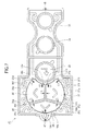
- Fig. 1 illustrates a pertinent portion of an image forming apparatus 1 that employs an operator panel 29 of a first embodiment.
- print engines 2K, 2Y, 2M, and 2C are aligned in this order in a direction of travel of paper.
- Transfer rollers 10K, 10Y, 10M, and 10C are disposed to face corresponding print engines 2K, 2Y, 2M, and 2C, respectively, such that an endless type transport belt 18 is sandwiched between the print engines 2K, 2Y, 2M, and 2C and the corresponding transfer rollers 10K, 10Y, 10M, and 10C.
- the transport belt 18 is disposed about a drive roller 17 and a driven roller 16.
- the transfer belt 18, drive roller 17, and driven roller 16 cooperate with one another to form a transfer unit 27.
- a paper cassette 24 holds a stack of paper therein.
- a feed roller 11 cooperates with a separator (not shown) to feed the top page of the stack of paper from the paper cassette 24.
- An entrance sensor 12 and a write sensor 13 are located upstream of transport rollers 14 and 15 with respect to the direction of travel of the paper, and downstream of the transport rollers 14 and 15.
- a fixing roller 19 incorporates a heat source such as a halogen lamp, and rotates in contact with a back up roller 20 so that a toner image on the paper is fused into a permanent image by heat and pressure.
- the print engines 2K, 2Y, 2M, and 2C include LED heads 3K, 3Y, 3M, and 3C, photoconductive drums 4K, 4Y, 4M, and 4C, charging rollers 5K, 5Y, 5M, and 5C, developing rollers 6K, 6Y, 6M, and 6C, toner reservoirs 7K, 7Y, 7M, and 7C, developing blades 8K, 8Y, 8M, and 8C, and toner supplying rollers 9K, 9Y, 9M, and 9Y, respectively.
- the image forming apparatus 1 includes the operator panel 29 at a front portion of the image forming apparatus 1, allowing a user to input a variety of settings. The operator panel 29 will now be described in detail.
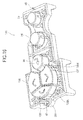
- Fig. 2 is a perspective view of the operator panel 29 as seen in a direction shown by arrow A of Fig. 1 .
- a display section 30 is, for example, a liquid crystal display (LCD), and displays the operational statuses and various settings of the image forming apparatus 1.
- An on-line key 34 may be switched between a reception mode where the image forming apparatus is ready for receiving information from a host apparatus and a non-reception mode where the image forming apparatus is not ready for receiving information from the host apparatus.
- a cancel key 35 is operated by the user if a printing operation should be halted in the middle of printing.
- Upper and lower menu keys 36 and 37 are operated to set the number of pages to be copied and the type of print medium.
- An enter key 38 is depressed for confirming various settings after making selection.
- a back key 39 is operated if the user wants to return to one immediately previous page of a screen that displays various settings.
- a help key 40 is operated for displaying the details of malfunctions such as paper jam.
- a shut down key 41 is depressed if the image forming apparatus 1 is to be turned off. The aforementioned keys depressed by the user are referred to as operational keys hereinafter.
- Fig. 3 is a front view of the operator panel 29.
- Fig. 4 is a cross-sectional view taken along a line B-B of Fig. 3 .
- Fig. 5A is a partial expanded cross-sectional view of a portion 500 of Fig. 4 encircled by a dot-dash line.
- Fig. 5B is a partial expanded view of Fig. 5A .
- Fig. 5C is a partial expanded view of Fig. 5A .
- Fig. 6 is a perspective view of the case 33 as seen obliquely from above.
- the operator panel 29 includes a variety of sections in addition to the aforementioned display 30 and the operational keys 34-41.
- a display cover 31 is colorless and clear, and covers the front surface of the display 30.
- a circuit board 32 controls the information received from the operational keys 34-41.
- the case 33 accommodates the operational keys 39-41, display 30, display cover 31, and circuit board 32, and serves as an outer decorated panel.
- the operational keys 34-41 each include a pressing portion 42. The pressing portion 42 is immediately over a switch 43 mounted to the circuit board 32. When the operational keys 34-41 are depressed by the user, the switches 43 are shifted to their ON-position or OFF-position.
- An on-line key 34, the cancel key 35, upper menu key 36, the lower menu key 37, the back key 39, the enter key 38, and a frame 44 are molded from, for example, a synthetic resin material in one piece construction such that these elements form a button key assembly 45 as a whole.
- the button keys assembly 45 will be described in more detail.
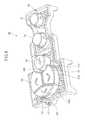
- Fig. 7 is a front view of the button key assembly 45.
- Fig. 8 is a perspective view of the button key assembly 45 as seen obliquely from above.
- the operational keys 34-39 are in one piece with resilient supporting arms 36f, 36g, 39d, 39e, 37g, and 37f and the frame 44 such that the operational keys 34-39 may be displaceable by a predetermined short distance.
- Supporting arms 36f and 36g are formed between the upper menu key 36 and the frame 44.
- Supporting arms 37f and 37g are formed between the lower menu key 37 and the frame 44.
- Supporting arms 39d and 39e are formed between the back key 39 and the frame 44.
- the upper key 36, lower key 37 and back key 39 are spaced apart from one another by a predetermined, distance or a first gap T1 (e.g., 0.8 mm. Figs. 7 and 12 ) before the button key assembly 45 has been assembled to the case 33.
- a mold used for one-piece molding of the button key assembly 45 has sufficient mechanical strength in all structural portions.
- the portions of the mold corresponding to the first gap T1 should have a minimum, sufficient thickness.
- the configuration of the aforementioned operational keys 34-39 having the first gap T1 ensures mechanical and structural strength of the mold used for one-piece molding.
- the supporting arms each have one end fixed to the frame 44 and another end fixed to the corresponding operational keys, thereby supporting the operational keys such that the operational keys are resiliently movable in directions parallel to the direction in which the operational keys are depressed and in the directions substantially perpendicular to the directions in which the operational keys are depressed.
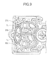
- Fig. 9 is a perspective view of the button key assembly 45 as seen obliquely from above.
- the first gap T1 exists between a back key wall portion 39b that extends from the surface of the back key 39 in a direction in which the back key 39 is depressed, and an upper menu key wall 36c that extends in the direction in which the upper menu key 36 is depressed.
- the first gap T1 also exists between the back key wall portion 39b that extends in the direction in which the back key 39 is depressed, and the lower menu key wall 37c that extends from the surface of the lower menu key 37c in the direction in which the lower menu key 37 is depressed.
- abutments 36d and 36e are formed on side surfaces 36a and 36b of the upper menu key 36.
- the abutments 36d ( Fig. 5A ) and 36e have short beveled surfaces 46a ( Fig. 5C ) that facilitate the movement of the upper menu key 36 when the button key assembly 45 is assembled to the case 33.
- Abutments 37d ( Fig. 8 ) and 37c are formed on side surfaces 37a and 37b of the lower menu key 37.
- the abutments 37d and 37e have beveled surfaces 46b (not shown) that facilitate the movement of the lower menu key 37 when the button key assembly 45 is assembled to the case 33.
- An abutment 39c ( Figs.
- the beveled surfaces 46a-46c should be formed at positions where the beveled surfaces are below the surface of the case 33 after the button assembly 45 has been assembled the case 33 for pleasant appearance of the keyboard.
- Fig. 10 illustrates the operation of the button key assembly 45.
- the supporting arm 36g and the supporting arm 36f connect the frame 44 and the upper menu key 36 together.
- the supporting arm 36g and the supporting arm 36f include knee bends 36k (sharply curved portions) and 36n and 36m, respectively, for providing resiliency that allows the upper menu key 36 to resiliently displace in directions shown by arrows U1 and U2.
- the supporting arm 37g and the supporting arm 37f connect the frame 44 and the lower menu key 37 together.
- the supporting arm 37g and the supporting arm 37f include knee bends 37k (sharply curved portion) and 37n and 37m, respectively, for providing resiliency that allows the lower menu key 37 to resiliently displace in directions shown by arrows L1 and L2. Still likewise, the supporting arm 39d and the supporting arm 39e connect the frame 44 and the back key 39 together.
- the supporting arm 39d and the supporting arm 39e include knee bends 39f and 39g (sharply curved portion) and knee bends 39h and 39i, respectively, for providing resiliency that allows the back key 39 to resiliently displace in a direction shown by arrow B1.
- the upper menu key 36, lower menu key 37, and back key 39 each include at least one knee bend in their corresponding supporting arms such that the knee bend provides resiliency of the key in specific directions.
- the knee bends resiliently deform such that these keys are allowed to resiliently displace in the U1 and U2 directions, the L1 and L2 directions, and the B1 direction, respectively.
- Fig. 11 illustrates an angle ⁇ through which a portion 102 curves relative to a portion 101 about a bent portion 100.
- the respective knee bends are bent by the angle ⁇ equal to or greater than 90 degrees and not larger than 180 degrees so that the respective supporting arms may be resiliently deformed without difficulty.
- the frame 44 includes a first post 47 ( Figs. 4 and 7 ) and a second post 48 that are located at longitudinal end portions of the frame 44 and at substantially midway between widthwise ends of the frame 44.
- the button key assembly 45 is assembled to the case 33 ( Fig. 6 )
- the first and second posts 47 and 48 are fittingly received in a circular recess 49 and an elongated circular recess 50, respectively.
- the display section 30 is electrically connected to a circuit board 32 via cables (not shown).
- the display section 30 and the display cover 31 are securely mounted to the case 33 by means of, for example, screws (not shown) such that the display cover 31 covers the front side of the display section 30.
- the circuit board 32 includes a round hole 51 and an elongated hole 52 spaced apart by a predetermined distance.
- the case 33 includes a first post 53 and a second post 54 formed thereon, and received in the round hole 51 and elongated hole 52, respectively.
- the circuit board 32 is fixed to the case 33 by means of, for example, screws.
- the case 33 includes a single button hole 56 for receiving the upper menu key 36, lower menu key 37, and back key 39 therein, and includes no partitions that isolate these operational keys from one another.
- the button hole 56 has a perimeter portion 56a and a perimeter portion 56b.
- the upper menu key 36, lower menu key 37, and back key 39 are spaced apart from one another by the first gap T1 (e.g., 0.8 mm) before the button key assembly 45 is assembled to the case 33.
- the side surface 36a of the upper menu key 36, side surface 37a of the lower menu key 37, and side surface 39a of the back key 39 have a radius of curvature substantially the same as the surface of the perimeter portion 56a of the button hole 56, so that the side surfaces 36a and 37a may comfortably slide on the perimeter portion 56a once the button key assembly 45 has been assembled to the case 33.
- the side surface 36b of the upper menu key 36 and the side surface 37b of the lower menu key 37 have a radius of curvature substantially the same as the surface of a perimeter portion 56b of the button hole 56, so that the side surfaces 36b and 37b may comfortably slide on the perimeter portion 56b.
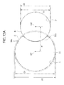
- Fig. 12A illustrates the various dimensions of the button hole 56.
- Fig. 12B illustrates the various dimensions of the upper menu key 36, lower menu key 37 and back key 39 after the button key assembly 45 has been assembled to the case 33.
- Fig. 12C illustrates the positional relationship among the upper menu key 36, lower menu key 37 and back key 39 after the button key assembly 45 has been assembled to the case 33.
- the perimeter portion 56a includes a diameter D1 equivalent to the diameter of an imaginary circle A (centered at "201"), and the perimeter portion 56b includes a diameter D3 equivalent to the diameter of an imaginary circle B (centered at "202").
- the center-to-center distance W between the two imaginary circles A and B is selected such that the two imaginary circles A and B overlap each other by a predetermined amount.
- the upper menu key 36, lower menu key 37, and back key 39 are spaced apart from one another by the first gap T1 (e.g., 0.8 mm) before the button key assembly 45 has been mounted to the case 33, and the side surface 36a, side surface 37a, and side surface 39a have a radius of curvature substantially the same as that of the imaginary circle A having the diameter D1 about the center 201.
- the abutments 36d, 37d, and 39c project further radially outwardly than the diameter of the perimeter portion 56a of the button hole 56, i.e., an imaginary circle C that is circumscribed around the abutments 36d, 37d, and 39c has a diameter D2 slightly larger than the diameter D1.
- the diameters D, D2, D3, and D4 are 33 mm, 33.6 mm, 21.6 mm, and 21 mm in the first embodiment.
- the imaginary circle B having the diameter D3 lies on the side surface 36b of the upper menu key 36 and the side surface 37b of the lower menu key 37.
- An imaginary circle D that is circumscribed around the abutments 36e and 37e has a diameter D4 slightly smaller than the diameter D3.
- the abutments 36e and 37e project from the upper menu key 36 and lower menu key 37 radially outwardly from the center 201 further than the perimeter portion 56b of the button hole 56 before the button key assembly 45 has been assembled to the case 33.
- the upper menu key 36 and lower menu key 37 are on either side of an imaginary plane cutting through the passing through the first and second posts 47 and 48 and generally perpendicular to the front surface of the case 33, and are mirror images of one another.
- Another way of looking at the assembly is that the upper menu key 36 and lower menu key 37 are symmetrical with respect to a line passing through the centers 201 and 202.
- the back key 39 is symmetrical about the line passing through the centers 201 and 202.
- a second gap T2 smaller than the first gap T1 is maintained between the perimeter portion 56a and the surface 36a, between the perimeter portion 56a and the side surface 37a, and between the perimeter portion 56a and the side surface 39a.
- the radius of curvature of the perimeter portion 56b is substantially equal to that of surface 36b and side surface 37b.
- the side surfaces 36a and 37a may be any shape as long as they do not outwardly extend further from the center 201 than the imaginary circle C having the diameter D2.
- the side surfaces 36b and 37b may be of any shape as long as they do not outwardly extend further from the center 201 than the imaginary circle D having the diameter D4.
- the side surfaces 36a, 37a, and 39a are designed to have a diameter of 33 mm
- the side surfaces 36b and 37b are designed to have a diameter of 21. 6 mm
- the first post 47 and the second post 48 When a user wants to select, for example, the number of pages to be printed and the type of a medium to be printed on, he depresses the upper menu key 36, lower menu key 37, and back key 39 to select appropriate settings. As described previously, once the first post 47 and the second post 48 have been fittingly received in the circular recess 49 ( Fig. 4 ) and the elongated circular recess 50, respectively, the first post 47 and second post 48 are positioned accurately in a plane normal to the direction in which the operational keys are pressed.
- the surfaces of the abutments 36d, 37d, and 39c are inscribed in the imaginary circle C having the diameter D2 larger than the diameter of the perimeter portion 56a. Therefore, when the upper menu key 36, lower menu key 37, and back key 39 are inserted in the button hole 56, the abutments 36d, 37d, and 39c abut the perimeter portion 56a of the button hole 56. Because the surfaces of the abutments 36e and 37e are on the circumference of the imaginary circle D having a diameter D4 smaller than the perimeter portion 56b of the button hole 56, the abutments 36e and 37e are pressed against the perimeter portion 56b of the button hole 56.
- the upper menu key 36, lower menu key 37, and back key 39 are pushed by the perimeter portions 56a and 56b in the U1 and U2 directions, L1 and L2 directions, and B1 direction, respectively, as shown in Fig. 10 .
- the knee bends 36k, 36n, 36m, 37k, 37n, 37m, 39f, 39g, 39h, and 39i resiliently deform such that the upper menu key 36, lower menu key 37, and back key 39 are displaced in such directions as to reduce the gap between adjacent ones of these keys from the first gap T1 (e.g., approx. 0.8 mm) to the second gap T2 (e.g., approx. 0.2 mm).
- the second gap T2 between adjacent ones of these keys 36, 37, 39 is smaller than the first gap T1 (e.g., 0.8 mm), the difference in gap being equal to the difference between the diameter of the button hole 56 and the diameter of the imaginary circle C in which the abutments 36d, 36e, 37d, 37e, and 39c are inscribed.
- the decrease in the gap in this manner is effective in minimizing rattling of the operational keys after the button key assembly 45 has been assembled to the case 33. The difference is approx.
- the abutments 36d, 36e, 39c, 37d, 37e of the respective operational keys abut the perimeter portions 56a and 56b of the button hole 56, thereby decreasing the gaps from the first gap T1 to the second gap T2.
- the invention is not limited to this.
- the abutments of the respective operational keys may abut other portions of the case 33 than the perimeter portions 56a and 56b of the button hole 56, so that the first gaps T1 decrease to the second gaps T2.
- the abutment 36d, 36e, 37d, 37e, and 39c abut the perimeter portions 56a and 56b, so that the gaps between adjacent ones of the upper menu key 36, lower menu key 37, and back key 39 may be decreased from the first gap T1 to the second gap T2.
- the rattling of the operational keys due to the smaller second gaps T2 between adjacent ones of the operational keys is minimized.
- the configuration is effective in minimizing the rattling of the operational keys in directions perpendicular to the direction in which the operational keys are depressed, thereby improving the operability of the operational keys.
- the first embodiment allows the operational keys to be spaced apart by the sufficiently large gap (e.g., T1 shown in Fig. 7 ) during the manufacture of the button key assembly 45 by molding.
- the mold for molding the operational keys may be designed to have sufficient mechanical strength.
- Fig. 13 is a front view illustrating an operator panel 129 of a second embodiment.
- Fig. 14 is a cross-sectional view taken along a line B-B of Fig. 13 .
- Fig. 15 is a partial expanded view of an area depicted at 500 shown in Fig. 13 .
- Fig. 16 is a perspective view of a button key assembly 145 as seen obliquely from above.
- Fig. 17 is a perspective view of the button key assembly 145 as seen obliquely from under.
- the operator panel 129 differs from the operator panel 29 in the configuration of an upper menu key 136, a lower menu key 137, and a back key 139. Elements similar to those in the first embodiment have been given the same reference numerals and their description is omitted.
- the configuration of the image forming apparatus 1 of the second embodiment is the same as that of the image forming apparatus 1 of the first embodiment except for the operator panel 129. Thus, the second embodiment will be described with reference to Fig. 1 as required.
- the upper menu key 136 and lower menu key 137 are on either side of an imaginary plane cutting through the passing through the first and second posts 47 and 48 and generally perpendicular to the front surface of the operator panel 129, and are mirror images of one another. Another way to look at this configuration is that the upper menu key 136 and lower menu key 137 are symmetrical with respect to an imaginary plane generally perpendicular to the front surface of the operator panel 129.
- the back key 139 is also symmetrical with respect to the imaginary plane. Referring to Figs.
- the upper menu key 136 includes a projection 136a that extends over a distance substantially equal to a half of the thickness of an upper portion of the upper menu key 136, extending in a direction in which the upper menu key 136 is pressed. There is a predetermined gap or a first gap T1 (e.g., 0.8 mm) between a projection 139b of the back key 139 and a side surface 136b of the upper menu key 136.
- the upper menu key 136 includes a side surface 136c that extends from the projection 136a in a direction parallel to the direction in which, the upper menu key 136 is pressed. The side surface 136c is further away from the projection 139b than the side surface 136b.
- the upper menu key 136 further includes a rib 136d formed on the side surface 136c, the rib 136d extending from the projection 136a in the direction in which the upper menu key 136 is pressed.
- the rib 136d includes a surface flush with the side surface 136b of the back key 139. In other words, the surface of the rib 136d and the side surface 136b lie in the same plane.
- the second gap T2 is only about 0.2 mm. Therefore, when the user depresses the back key 39, the back key 39 is difficult to move while maintaining this small gap T2. As the back key 39 moves, the back key wall portion 39b slides on the upper menu key wall 36c and the lower menu key wall 37c.
- the first gap T1 between adjacent ones of the upper menu key 136, lower menu key 137, and back key 139 is defined by the projection 139b, the side surfaces 136b and 137b.
- the rib 136d is flush with the side surface 136b, and extends in a direction parallel to the direction in which the back key 139 is pressed.
- the rib 137d is also flush with the surface 137b, and extends in a direction parallel to the direction in which the back key 139 is depressed.
- the projection 139b slides on the rib 136d and the rib 137d. The remaining portion of the operation is the same as that described in the first embodiment, and the description thereof is omitted.
- the pressed key moves while being in contact with the adjacent keys. It is to be noted that the pressed key has a smaller total area in contact with the adjacent keys in the second embodiment than in the first embodiment.
- the configuration of the button key assembly 145 provides substantially the same advantages as the button key assembly 45 of the first embodiment.
- the smaller total area of an operational key in contact with the adjacent keys is effective in minimizing the friction between the pressed operational key and the adjacent operational keys, thus facilitating the smooth movement of the pressed operational key.
- the configuration of the second embodiment improves the ease of operation of the operational keys.
- the first gap T1 defined between upper menu key 136 and the back key 139, and the first gap T1 defined between the lower menu key 137 and the back key 139 do not extend over a great depth, eliminating extremely thin portions of a mold so that the usable lifetime of the mold may be prolonged.
- the embodiments have been described with respect to an operator panel of an image forming apparatus, the invention may also be applicable to copying machines, printers, facsimile machines, personal computers, telephones, and gaming machines.
Description
- The present invention relates to a button key assembly of an operator panel incorporated in a variety of electronic equipment including copying machines, facsimile machines, personal computers, telephones, and gaming machines.
- Conventional electronic apparatuses include an operator panel that employs a variety of operational keys that allow a user to operate the electronic apparatus. Such apparatuses include copying machines, facsimile machines, personal computers telephones, and gaming machines. An operator panel includes a variety of operational keys such as selection keys for selecting a variety of functions such as "ENTER" and "RETURN" for confirming the selection, and "BACK KEY" for returning to the immediately previous state. These keys are commonly arranged closely for the purposes of functionality and design.
- If a plurality of operational keys is to be closely located, the keys should be, for example, molded from a resin material in one-piece construction for minimum manufacturing cost. The mold should be designed such that adjacent keys are spaced apart by a predetermined distance or a gap. This gap may cause the keys to rattle after they have been assembled as a key board, impairing the operability of the keyboard.
-
US-A-2007209921 discloses a keyboard having keys closely located. - An objection of the present invention is to solve the aforementioned drawbacks, and to provide a keyboard that offers good operability.
- Another object of the invention is to provide a keyboard in which adjacent keys are spaced apart by as short a distance as possible so that the operability of the keyboard is least affected and excellent operability is obtained.
- A button key assembly, includes a frame (44), a plurality of adjacent button keys (36, 37, 39) connected to the frame (44) via a plurality of resilient supports (36f, 36g, 39d, 39e, 37g, 37f) such that the plurality of button keys are resiliently movable, and a case (33).
- The plurality of adjacent button keys (36, 37, 39) are connected to the frame (44) via a plurality of resilient supports (36f, 36g, 39d, 39e, 37g, 37f) such that the plurality of button keys are resiliently movable. The plurality of resilient supports, the plurality of button keys, and the frame (44) are formed in one-piece construction, and each of the plurality of button keys includes an engagement portion (36d, 39c, 37d, 36e, 37e). The case (33) includes a button hole (56) formed therein. The case is assembled to the frame (44) such that the plurality of button keys are received in the button hole. The plurality of adjacent button keys (36, 37, 39) are spaced apart by a first gap (T1) before the plurality of adjacent button keys have been received in the button hole (56). The plurality of adjacent button keys are spaced apart by a second gap (T2) after the case (33) has been assembled to the frame (44) such that the plurality of adjacent button keys are received in the button hole (56) and such that the engagement portion abuts a perimeter portion of the button hole (56), the second gap (T2) being smaller than the first gap (T1).
- Further scope of applicability of the present invention will become apparent from the detailed description given hereinafter. However, it should be understood that the detailed description and specific examples, while indicating preferred embodiments of the invention, are given by way of illustration only, since various changes and modifications within the spirit and scope of the invention will become apparent to those skilled in the art from this detailed description.
- The present invention will become more fully understood from the detailed description given hereinbelow and the accompanying drawings which are given by way of illustration only, and thus are not limiting the present invention, and wherein:
-
Fig. 1 illustrates a pertinent portion of an image forming apparatus of the invention; -
Fig. 2 is a perspective view of an operator panel as seen in a direction shown by arrow A ofFig. 1 ; -
Fig. 3 is a front view of the operator panel; -
Fig. 4 is a cross-sectional view taken along a line B-B ofFig. 3 ; -
Fig. 5A is an expanded cross-sectional view of a portion ofFig. 4 encircled by a dot-dash line; -
Fig. 5B is a partial expanded view ofFig. 5A ; -
Fig. 5C is a partial expanded view ofFig. 5A ; -
Fig. 6 is a perspective view of a case as seen obliquely from above; -
Fig. 7 is a front view of a button key assembly; -
Fig. 8 is a perspective view of the button key assembly as seen obliquely from above; -
Fig. 9 is a perspective view of the button key assembly as seen obliquely from above; -
Fig. 10 illustrates the operation of the button key assembly; -
Fig. 11 illustrates an angle through which a portion of a supporting arm curves relative to another portion about a bent portion; -
Fig. 12A illustrates various dimensions of a button hole; -
Fig. 12B illustrates various dimensions of an upper menu key, a lower menu key, and a back key after the button key assembly has been assembled to the case; -
Fig. 12C illustrates the positional relationship among the upper menu key, lower menu key and back key after the button key assembly has been assembled to the case; -
Fig. 13 is a front view illustrating an operator panel of a second embodiment; -
Fig. 14 is a cross-sectional view taken along a line B-B ofFig. 13 ; -
Fig. 15 is a partial expanded view of an area shown by a dot-dash line shown inFig. 13 ; -
Fig. 16 is a perspective view of a button key assembly of the second embodiment as seen obliquely from above; and -
Fig. 17 is a perspective view of the button key assembly as seen obliquely from under. -
Fig. 1 illustrates a pertinent portion of animage forming apparatus 1 that employs anoperator panel 29 of a first embodiment. - Referring to
Fig. 1 ,print engines Transfer rollers corresponding print engines type transport belt 18 is sandwiched between theprint engines corresponding transfer rollers transport belt 18 is disposed about adrive roller 17 and a drivenroller 16. Thetransfer belt 18,drive roller 17, and drivenroller 16 cooperate with one another to form atransfer unit 27. Apaper cassette 24 holds a stack of paper therein. Afeed roller 11 cooperates with a separator (not shown) to feed the top page of the stack of paper from thepaper cassette 24. Anentrance sensor 12 and awrite sensor 13 are located upstream oftransport rollers transport rollers fixing roller 19 incorporates a heat source such as a halogen lamp, and rotates in contact with a back uproller 20 so that a toner image on the paper is fused into a permanent image by heat and pressure. - The
print engines LED heads photoconductive drums charging rollers rollers toner reservoirs blades toner supplying rollers image forming apparatus 1 includes theoperator panel 29 at a front portion of theimage forming apparatus 1, allowing a user to input a variety of settings. Theoperator panel 29 will now be described in detail. -
Fig. 2 is a perspective view of theoperator panel 29 as seen in a direction shown by arrow A ofFig. 1 . - Referring to
Fig. 2 , adisplay section 30 is, for example, a liquid crystal display (LCD), and displays the operational statuses and various settings of theimage forming apparatus 1. An on-line key 34 may be switched between a reception mode where the image forming apparatus is ready for receiving information from a host apparatus and a non-reception mode where the image forming apparatus is not ready for receiving information from the host apparatus. A cancelkey 35 is operated by the user if a printing operation should be halted in the middle of printing. Upper andlower menu keys enter key 38 is depressed for confirming various settings after making selection. Aback key 39 is operated if the user wants to return to one immediately previous page of a screen that displays various settings. Ahelp key 40 is operated for displaying the details of malfunctions such as paper jam. A shut down key 41 is depressed if theimage forming apparatus 1 is to be turned off. The aforementioned keys depressed by the user are referred to as operational keys hereinafter. -
Fig. 3 is a front view of theoperator panel 29.Fig. 4 is a cross-sectional view taken along a line B-B ofFig. 3 .Fig. 5A is a partial expanded cross-sectional view of aportion 500 ofFig. 4 encircled by a dot-dash line.Fig. 5B is a partial expanded view ofFig. 5A .Fig. 5C is a partial expanded view ofFig. 5A .Fig. 6 is a perspective view of thecase 33 as seen obliquely from above. - Referring to
Figs. 3 and4 , theoperator panel 29 includes a variety of sections in addition to theaforementioned display 30 and the operational keys 34-41. Adisplay cover 31 is colorless and clear, and covers the front surface of thedisplay 30. Acircuit board 32 controls the information received from the operational keys 34-41. Thecase 33 accommodates the operational keys 39-41,display 30,display cover 31, andcircuit board 32, and serves as an outer decorated panel. The operational keys 34-41 each include apressing portion 42. Thepressing portion 42 is immediately over aswitch 43 mounted to thecircuit board 32. When the operational keys 34-41 are depressed by the user, theswitches 43 are shifted to their ON-position or OFF-position. - An on-
line key 34, the cancel key 35,upper menu key 36, thelower menu key 37, the back key 39, theenter key 38, and aframe 44 are molded from, for example, a synthetic resin material in one piece construction such that these elements form a buttonkey assembly 45 as a whole. Thebutton keys assembly 45 will be described in more detail. -
Fig. 7 is a front view of the buttonkey assembly 45.Fig. 8 is a perspective view of the buttonkey assembly 45 as seen obliquely from above. - The operational keys 34-39 are in one piece with resilient supporting
arms frame 44 such that the operational keys 34-39 may be displaceable by a predetermined short distance. Supportingarms upper menu key 36 and theframe 44. Supportingarms lower menu key 37 and theframe 44. Supportingarms frame 44. It is to be noted that theupper key 36,lower key 37 and back key 39 are spaced apart from one another by a predetermined, distance or a first gap T1 (e.g., 0.8 mm.Figs. 7 and12 ) before the buttonkey assembly 45 has been assembled to thecase 33. It is important that a mold used for one-piece molding of the buttonkey assembly 45 has sufficient mechanical strength in all structural portions. In order to ensure sufficient mechanical strength of the mold, the portions of the mold corresponding to the first gap T1 should have a minimum, sufficient thickness. The configuration of the aforementioned operational keys 34-39 having the first gap T1 ensures mechanical and structural strength of the mold used for one-piece molding. The supporting arms each have one end fixed to theframe 44 and another end fixed to the corresponding operational keys, thereby supporting the operational keys such that the operational keys are resiliently movable in directions parallel to the direction in which the operational keys are depressed and in the directions substantially perpendicular to the directions in which the operational keys are depressed. -
Fig. 9 is a perspective view of the buttonkey assembly 45 as seen obliquely from above. - Thus, as shown in
Fig. 9 , the first gap T1 exists between a backkey wall portion 39b that extends from the surface of the back key 39 in a direction in which the back key 39 is depressed, and an upper menukey wall 36c that extends in the direction in which theupper menu key 36 is depressed. The first gap T1 also exists between the backkey wall portion 39b that extends in the direction in which the back key 39 is depressed, and the lower menukey wall 37c that extends from the surface of the lower menu key 37c in the direction in which thelower menu key 37 is depressed. - Referring to
Figs. 5A-5B ,7 , and8 ,abutments side surfaces upper menu key 36. Theabutments 36d (Fig. 5A ) and 36e have shortbeveled surfaces 46a (Fig. 5C ) that facilitate the movement of theupper menu key 36 when the buttonkey assembly 45 is assembled to thecase 33.Abutments 37d (Fig. 8 ) and 37c are formed onside surfaces lower menu key 37. Theabutments lower menu key 37 when the buttonkey assembly 45 is assembled to thecase 33. Anabutment 39c (Figs. 5 and8 ) is formed on aside surface 39a of the back key 39, and has beveledsurfaces 46c (Fig. 5B ) that facilitate the movement of theback key 39. Thebeveled surfaces 46a-46c should be formed at positions where the beveled surfaces are below the surface of thecase 33 after thebutton assembly 45 has been assembled thecase 33 for pleasant appearance of the keyboard. -
Fig. 10 illustrates the operation of the buttonkey assembly 45. Referring toFig. 10 , the supportingarm 36g and the supportingarm 36f connect theframe 44 and theupper menu key 36 together. The supportingarm 36g and the supportingarm 36f include knee bends 36k (sharply curved portions) and 36n and 36m, respectively, for providing resiliency that allows the upper menu key 36 to resiliently displace in directions shown by arrows U1 and U2. Likewise, the supportingarm 37g and the supportingarm 37f connect theframe 44 and thelower menu key 37 together. The supportingarm 37g and the supportingarm 37f include knee bends 37k (sharply curved portion) and 37n and 37m, respectively, for providing resiliency that allows thelower menu key 37 to resiliently displace in directions shown by arrows L1 and L2. Still likewise, the supportingarm 39d and the supportingarm 39e connect theframe 44 and the back key 39 together. The supportingarm 39d and the supportingarm 39e includeknee bends knee bends 39h and 39i, respectively, for providing resiliency that allows the back key 39 to resiliently displace in a direction shown by arrow B1. - As described above, the
upper menu key 36,lower menu key 37, and back key 39 each include at least one knee bend in their corresponding supporting arms such that the knee bend provides resiliency of the key in specific directions. In other words, when external forces are exerted on theupper menu key 36,lower menu key 37, and back key 39, the knee bends resiliently deform such that these keys are allowed to resiliently displace in the U1 and U2 directions, the L1 and L2 directions, and the B1 direction, respectively. -
Fig. 11 illustrates an angle θ through which aportion 102 curves relative to aportion 101 about abent portion 100. The respective knee bends are bent by the angle θ equal to or greater than 90 degrees and not larger than 180 degrees so that the respective supporting arms may be resiliently deformed without difficulty. - Referring back to
Figs. 3 and4 , theframe 44 includes a first post 47 (Figs. 4 and7 ) and asecond post 48 that are located at longitudinal end portions of theframe 44 and at substantially midway between widthwise ends of theframe 44. When the buttonkey assembly 45 is assembled to the case 33 (Fig. 6 ), the first andsecond posts circular recess 49 and an elongatedcircular recess 50, respectively. Thedisplay section 30 is electrically connected to acircuit board 32 via cables (not shown). Thedisplay section 30 and thedisplay cover 31 are securely mounted to thecase 33 by means of, for example, screws (not shown) such that thedisplay cover 31 covers the front side of thedisplay section 30. - The
circuit board 32 includes around hole 51 and anelongated hole 52 spaced apart by a predetermined distance. Thecase 33 includes afirst post 53 and asecond post 54 formed thereon, and received in theround hole 51 andelongated hole 52, respectively. Thecircuit board 32 is fixed to thecase 33 by means of, for example, screws. - Referring to
Fig. 6 , thecase 33 includes asingle button hole 56 for receiving theupper menu key 36,lower menu key 37, and back key 39 therein, and includes no partitions that isolate these operational keys from one another. Thebutton hole 56 has aperimeter portion 56a and aperimeter portion 56b. - The engagement relation among the
button hole 56, theabutments upper menu key 36, theabutments lower key 37, theabutment 39c of the back key 39 will be described. - The
upper menu key 36,lower menu key 37, and back key 39 are spaced apart from one another by the first gap T1 (e.g., 0.8 mm) before the buttonkey assembly 45 is assembled to thecase 33. Theside surface 36a of theupper menu key 36,side surface 37a of thelower menu key 37, andside surface 39a of the back key 39 have a radius of curvature substantially the same as the surface of theperimeter portion 56a of thebutton hole 56, so that the side surfaces 36a and 37a may comfortably slide on theperimeter portion 56a once the buttonkey assembly 45 has been assembled to thecase 33. Likewise, theside surface 36b of theupper menu key 36 and theside surface 37b of thelower menu key 37 have a radius of curvature substantially the same as the surface of aperimeter portion 56b of thebutton hole 56, so that the side surfaces 36b and 37b may comfortably slide on theperimeter portion 56b. - The relation between the diameter of the
perimeter 56a of thebutton hole 56, and the radii of theupper menu key 36,lower menu key 37, and back key 39 will be described with reference toFigs. 12A-12C .Fig. 12A illustrates the various dimensions of thebutton hole 56.Fig. 12B illustrates the various dimensions of theupper menu key 36,lower menu key 37 and back key 39 after the buttonkey assembly 45 has been assembled to thecase 33.Fig. 12C illustrates the positional relationship among theupper menu key 36,lower menu key 37 and back key 39 after the buttonkey assembly 45 has been assembled to thecase 33. - Referring to
Fig. 12A , theperimeter portion 56a includes a diameter D1 equivalent to the diameter of an imaginary circle A (centered at "201"), and theperimeter portion 56b includes a diameter D3 equivalent to the diameter of an imaginary circle B (centered at "202"). The center-to-center distance W between the two imaginary circles A and B is selected such that the two imaginary circles A and B overlap each other by a predetermined amount. - Referring to
Fig. 12B , theupper menu key 36,lower menu key 37, and back key 39 are spaced apart from one another by the first gap T1 (e.g., 0.8 mm) before the buttonkey assembly 45 has been mounted to thecase 33, and theside surface 36a,side surface 37a, andside surface 39a have a radius of curvature substantially the same as that of the imaginary circle A having the diameter D1 about thecenter 201. Further, theabutments perimeter portion 56a of thebutton hole 56, i.e., an imaginary circle C that is circumscribed around theabutments - The imaginary circle B having the diameter D3 lies on the
side surface 36b of theupper menu key 36 and theside surface 37b of thelower menu key 37. An imaginary circle D that is circumscribed around theabutments abutments upper menu key 36 andlower menu key 37 radially outwardly from thecenter 201 further than theperimeter portion 56b of thebutton hole 56 before the buttonkey assembly 45 has been assembled to thecase 33. It is to be noted that theupper menu key 36 andlower menu key 37 are on either side of an imaginary plane cutting through the passing through the first andsecond posts case 33, and are mirror images of one another. Another way of looking at the assembly is that theupper menu key 36 andlower menu key 37 are symmetrical with respect to a line passing through thecenters centers - As described above, a second gap T2 smaller than the first gap T1 is maintained between the
perimeter portion 56a and thesurface 36a, between theperimeter portion 56a and theside surface 37a, and between theperimeter portion 56a and theside surface 39a. The radius of curvature of theperimeter portion 56b is substantially equal to that ofsurface 36b andside surface 37b. The side surfaces 36a and 37a may be any shape as long as they do not outwardly extend further from thecenter 201 than the imaginary circle C having the diameter D2. The side surfaces 36b and 37b may be of any shape as long as they do not outwardly extend further from thecenter 201 than the imaginary circle D having the diameter D4. - For example, if the
perimeter portion 56a of thebutton hole 56 has a diameter of 33 mm, and theperimeter portion 56b of thebutton hole 56 has a diameter of 21.6 mm, then the side surfaces 36a, 37a, and 39a are designed to have a diameter of 33 mm, the side surfaces 36b and 37b are designed to have a diameter of 21. 6 mm, theabutments abutments key assembly 45 has been assembled to thecase 33. - The operation of the button keys of the aforementioned configuration will be described.
- When a user wants to select, for example, the number of pages to be printed and the type of a medium to be printed on, he depresses the
upper menu key 36,lower menu key 37, and back key 39 to select appropriate settings. As described previously, once thefirst post 47 and thesecond post 48 have been fittingly received in the circular recess 49 (Fig. 4 ) and the elongatedcircular recess 50, respectively, thefirst post 47 andsecond post 48 are positioned accurately in a plane normal to the direction in which the operational keys are pressed. - The surfaces of the
abutments perimeter portion 56a. Therefore, when theupper menu key 36,lower menu key 37, and back key 39 are inserted in thebutton hole 56, theabutments perimeter portion 56a of thebutton hole 56. Because the surfaces of theabutments perimeter portion 56b of thebutton hole 56, theabutments perimeter portion 56b of thebutton hole 56. - When the button
key assembly 45 has been assembled to thecase 33, theupper menu key 36,lower menu key 37, and back key 39 are pushed by theperimeter portions Fig. 10 . Thus, the knee bends 36k, 36n, 36m, 37k, 37n, 37m, 39f, 39g, 39h, and 39i resiliently deform such that theupper menu key 36,lower menu key 37, and back key 39 are displaced in such directions as to reduce the gap between adjacent ones of these keys from the first gap T1 (e.g., approx. 0.8 mm) to the second gap T2 (e.g., approx. 0.2 mm). - Once the
upper menu key 36,lower menu key 37, and back key 39 have been assembled to thecase 33, the second gap T2 between adjacent ones of thesekeys button hole 56 and the diameter of the imaginary circle C in which theabutments key assembly 45 has been assembled to thecase 33. The difference is approx. 0.6 mm, providing that theperimeter portions abutments abutments - In the first embodiment, the
abutments perimeter portions button hole 56, thereby decreasing the gaps from the first gap T1 to the second gap T2. However, the invention is not limited to this. For example, the abutments of the respective operational keys may abut other portions of thecase 33 than theperimeter portions button hole 56, so that the first gaps T1 decrease to the second gaps T2. - As described above, when the
upper menu key 36,lower menu key 37, and back key 39 have been inserted into thebutton hole 56, theabutment perimeter portions upper menu key 36,lower menu key 37, and back key 39 may be decreased from the first gap T1 to the second gap T2. Thus, the rattling of the operational keys due to the smaller second gaps T2 between adjacent ones of the operational keys is minimized. For example, the configuration is effective in minimizing the rattling of the operational keys in directions perpendicular to the direction in which the operational keys are depressed, thereby improving the operability of the operational keys. - The first embodiment allows the operational keys to be spaced apart by the sufficiently large gap (e.g., T1 shown in
Fig. 7 ) during the manufacture of the buttonkey assembly 45 by molding. Thus, the mold for molding the operational keys may be designed to have sufficient mechanical strength. -
Fig. 13 is a front view illustrating anoperator panel 129 of a second embodiment. -
Fig. 14 is a cross-sectional view taken along a line B-B ofFig. 13 . -
Fig. 15 is a partial expanded view of an area depicted at 500 shown inFig. 13 . -
Fig. 16 is a perspective view of a buttonkey assembly 145 as seen obliquely from above. -
Fig. 17 is a perspective view of the buttonkey assembly 145 as seen obliquely from under. - Referring to
Fig. 13 , theoperator panel 129 differs from theoperator panel 29 in the configuration of anupper menu key 136, alower menu key 137, and aback key 139. Elements similar to those in the first embodiment have been given the same reference numerals and their description is omitted. The configuration of theimage forming apparatus 1 of the second embodiment is the same as that of theimage forming apparatus 1 of the first embodiment except for theoperator panel 129. Thus, the second embodiment will be described with reference toFig. 1 as required. - Just as in the first embodiment, the
upper menu key 136 andlower menu key 137 are on either side of an imaginary plane cutting through the passing through the first andsecond posts operator panel 129, and are mirror images of one another. Another way to look at this configuration is that theupper menu key 136 andlower menu key 137 are symmetrical with respect to an imaginary plane generally perpendicular to the front surface of theoperator panel 129. Theback key 139 is also symmetrical with respect to the imaginary plane. Referring toFigs. 15-17 , theupper menu key 136 includes aprojection 136a that extends over a distance substantially equal to a half of the thickness of an upper portion of theupper menu key 136, extending in a direction in which theupper menu key 136 is pressed. There is a predetermined gap or a first gap T1 (e.g., 0.8 mm) between aprojection 139b of theback key 139 and aside surface 136b of theupper menu key 136. Theupper menu key 136 includes aside surface 136c that extends from theprojection 136a in a direction parallel to the direction in which, theupper menu key 136 is pressed. Theside surface 136c is further away from theprojection 139b than theside surface 136b. - The
upper menu key 136 further includes arib 136d formed on theside surface 136c, therib 136d extending from theprojection 136a in the direction in which theupper menu key 136 is pressed. Therib 136d includes a surface flush with theside surface 136b of theback key 139. In other words, the surface of therib 136d and theside surface 136b lie in the same plane. - The operation of the button keys of the aforementioned configuration will be described.
- In the first embodiment, once the button
key assembly 45 has been assembled to thecase 33, the second gap T2 is only about 0.2 mm. Therefore, when the user depresses the back key 39, the back key 39 is difficult to move while maintaining this small gap T2. As the back key 39 moves, the backkey wall portion 39b slides on the upper menukey wall 36c and the lower menukey wall 37c. - In the second embodiment, the first gap T1 between adjacent ones of the
upper menu key 136,lower menu key 137, and back key 139 is defined by theprojection 139b, the side surfaces 136b and 137b. In addition, therib 136d is flush with theside surface 136b, and extends in a direction parallel to the direction in which theback key 139 is pressed. Therib 137d is also flush with thesurface 137b, and extends in a direction parallel to the direction in which theback key 139 is depressed. When theback key 139 is depressed, theprojection 139b slides on therib 136d and therib 137d. The remaining portion of the operation is the same as that described in the first embodiment, and the description thereof is omitted. - When one of the
upper menu key 136,lower menu key 137, and back key 139 is pressed, the pressed key moves while being in contact with the adjacent keys. It is to be noted that the pressed key has a smaller total area in contact with the adjacent keys in the second embodiment than in the first embodiment. - As described above, the configuration of the button
key assembly 145 provides substantially the same advantages as the buttonkey assembly 45 of the first embodiment. The smaller total area of an operational key in contact with the adjacent keys is effective in minimizing the friction between the pressed operational key and the adjacent operational keys, thus facilitating the smooth movement of the pressed operational key. Thus, the configuration of the second embodiment improves the ease of operation of the operational keys. - The first gap T1 defined between
upper menu key 136 and theback key 139, and the first gap T1 defined between thelower menu key 137 and theback key 139 do not extend over a great depth, eliminating extremely thin portions of a mold so that the usable lifetime of the mold may be prolonged. - While the embodiments have been described in terms of three operational keys, i.e., upper menu key, lower menu key and back key, the invention is not limited to this. While the operational keys form a generally cylindrical appearance when they are assembled together, the invention is not limited to this. The adjacent operational keys may have any shape.
- Although the embodiments have been described with respect to an operator panel of an image forming apparatus, the invention may also be applicable to copying machines, printers, facsimile machines, personal computers, telephones, and gaming machines.
- The invention being thus described, it will be obvious that the same may be varied in many ways. Such variations are not to be regarded as a departure from the spirit and scope of the invention, and all such modifications as would be obvious to one skilled in the art intended to be included within the scope of the following claims.
- An exemplary embodiment of the present invention may be summarised as follows:
- Button keys (36, 37, 39), resilient supports (36f, 36g, 39d, 39e, 37g, 37f) and a frame (44) are molded in one piece such that the button keys are resiliently movable and are spaced apart by a gap. Each of the button keys includes an engagement portion (36d, 39c, 37d, 36e, 37e). A case (33) includes a button hole (56) formed therein. The case is assembled to the frame (44) such that the button keys are received in the button hole. After the case (33) has been assembled to the frame (44) such that the plurality of adjacent button keys are received in the button hole (56) and such that the engagement portion abuts a perimeter portion of the button hole (56), the second gap (T2) being smaller than the first gap (T1).
Claims (6)
- A button key assembly, comprising:a frame (44);a plurality of adjacent button keys (36, 37, 39) connected to said frame (44) via a plurality of resilient supports (36f, 36g, 39d, 39e, 37g, 37f) such that said plurality of button keys are resiliently movable, wherein said plurality of resilient supports, said plurality of button keys, and said frame (44) are formed in one-piece construction, and each of said plurality of button keys includes an engagement portion (36d, 39c, 37d, 36e, 37e); anda case (33) including a button hole (56) formed therein, said case being assembled to said frame (44) such that said plurality of button keys are received in the button hole;wherein said plurality of adjacent button keys (36, 37, 39) are spaced apart by a first gap (T1) before said plurality of adjacent button keys have been received in the button hole (56) ;wherein said plurality of adjacent button keys are spaced apart by a second gap (T2) after said case (33) has been assembled to said frame (44) such that said plurality of adjacent button keys are received in the button hole (56) and such that the engagement portion abuts a part of said case (33), the second gap (T2) being smaller than the first gap (T1).
- The button key assembly according to Claim 1, wherein the part of said case (33) forms a perimeter of the button hole (56).
- The button key assembly according to Claim 1 or 2, wherein the engagement portion (36d, 39c, 37d, 36e, 37e) projects in a direction substantially perpendicular to a direction in which a corresponding one of said plurality of button keys is depressed.
- The button key assembly according to any one of Claim 1 to Claim 3, wherein the plurality of resilient supports (36f, 36g, 39d, 39e, 37g, 37f) each includes at least one bent portion (100, 101, 102).
- The button key assembly according to any one of Claim 1 to Claim 4, wherein at least one of adjacent button keys of the plurality of button keys includes a surface (136c) facing the other of the adjacent button keys, the surface (136c) including a rib (136d) formed thereon and extending in a direction parallel to a direction in which the adjacent button keys are depressed.
- An electronic apparatus incorporating the button key assembly according to any one of Claim 1 to Claim 5.
Applications Claiming Priority (1)
| Application Number | Priority Date | Filing Date | Title |
|---|---|---|---|
| JP2008167385A JP4560569B2 (en) | 2008-06-26 | 2008-06-26 | Button key structure and electronic device apparatus |
Publications (3)
| Publication Number | Publication Date |
|---|---|
| EP2139015A2 EP2139015A2 (en) | 2009-12-30 |
| EP2139015A3 EP2139015A3 (en) | 2013-09-18 |
| EP2139015B1 true EP2139015B1 (en) | 2014-12-17 |
Family
ID=41050363
Family Applications (1)
| Application Number | Title | Priority Date | Filing Date |
|---|---|---|---|
| EP20090161124 Not-in-force EP2139015B1 (en) | 2008-06-26 | 2009-05-26 | Button key assembly and electronic apparatus that employs the button key assembly |
Country Status (3)
| Country | Link |
|---|---|
| US (1) | US8878083B2 (en) |
| EP (1) | EP2139015B1 (en) |
| JP (1) | JP4560569B2 (en) |
Families Citing this family (2)
| Publication number | Priority date | Publication date | Assignee | Title |
|---|---|---|---|---|
| JP5526116B2 (en) | 2011-12-19 | 2014-06-18 | 京セラドキュメントソリューションズ株式会社 | Button key structure of operation panel, operation panel and image forming apparatus |
| JP2022073217A (en) * | 2020-10-30 | 2022-05-17 | シャープ株式会社 | Input device and image forming apparatus having the same |
Family Cites Families (8)
| Publication number | Priority date | Publication date | Assignee | Title |
|---|---|---|---|---|
| JPH07114857A (en) * | 1993-10-19 | 1995-05-02 | Sanyo Electric Co Ltd | Multiple push button structure |
| JP2001236852A (en) | 2000-02-23 | 2001-08-31 | Murata Mach Ltd | Key structure |
| JP2001283677A (en) * | 2000-03-29 | 2001-10-12 | Tokai Rika Co Ltd | Switching device and its assembling method |
| US6555774B1 (en) * | 2000-07-28 | 2003-04-29 | Microsoft Corporation | Lever keyswitch |
| JP2003257279A (en) * | 2002-03-01 | 2003-09-12 | Sharp Corp | Key device |
| US7629548B2 (en) * | 2005-07-14 | 2009-12-08 | Access Business Group International Llc | Control panel assembly |
| JP2007200668A (en) * | 2006-01-25 | 2007-08-09 | Denso Corp | In-vehicle operation unit |
| TWI301284B (en) * | 2006-03-10 | 2008-09-21 | Hon Hai Prec Ind Co Ltd | Button assembly and electronic product employing the same |
-
2008
- 2008-06-26 JP JP2008167385A patent/JP4560569B2/en not_active Expired - Fee Related
-
2009
- 2009-05-26 EP EP20090161124 patent/EP2139015B1/en not_active Not-in-force
- 2009-05-29 US US12/457,020 patent/US8878083B2/en not_active Expired - Fee Related
Also Published As
| Publication number | Publication date |
|---|---|
| US8878083B2 (en) | 2014-11-04 |
| EP2139015A3 (en) | 2013-09-18 |
| EP2139015A2 (en) | 2009-12-30 |
| JP4560569B2 (en) | 2010-10-13 |
| JP2010009920A (en) | 2010-01-14 |
| US20090322569A1 (en) | 2009-12-31 |
Similar Documents
| Publication | Publication Date | Title |
|---|---|---|
| US5828015A (en) | Low profile keyboard keyswitch using a double scissor movement | |
| US5779030A (en) | Key board | |
| US7964808B2 (en) | Button apparatus and mobile appliance having the same | |
| US8022322B2 (en) | Key switch arrangement excellent in waterproofing property | |
| US8618429B2 (en) | Keypad assembly, and image forming device and data processor incorporating the same | |
| JP4597041B2 (en) | Operation panel and image forming apparatus | |
| KR19990053964A (en) | Pointing device mounting structure of electronic system | |
| EP2139015B1 (en) | Button key assembly and electronic apparatus that employs the button key assembly | |
| JP4650938B2 (en) | Push button mechanism, operation panel, and image forming apparatus | |
| JP2875697B2 (en) | Keyboard device | |
| JP2004079322A (en) | Keyboard and electronic appliance equipped therewith | |
| JP5696451B2 (en) | Process cartridge | |
| EP1361503A2 (en) | Eingabetastatur | |
| JP4785656B2 (en) | Operation panel and electronic device having the same | |
| EP1619702B1 (en) | Switch apparatus and image forming apparatus using thereof | |
| JP2000112629A (en) | Keyboard device | |
| JP4850888B2 (en) | Button key structure and electronic device | |
| US11776511B2 (en) | Keyboard device | |
| KR101748022B1 (en) | Image forming apparatus, molded resin product for use with the image forming apparatus, and cartridge | |
| KR100874830B1 (en) | Jog dial device and portable terminal equipped therewith | |
| JP4985075B2 (en) | Cursor key switch device | |
| JP2933574B2 (en) | keyboard | |
| CN219979392U (en) | Key assembly and electronic equipment | |
| KR100874648B1 (en) | Jog dial device and portable terminal equipped therewith | |
| US20170310833A1 (en) | Input device having push-keys, and image forming apparatus having the same |
Legal Events
| Date | Code | Title | Description |
|---|---|---|---|
| PUAI | Public reference made under article 153(3) epc to a published international application that has entered the european phase |
Free format text: ORIGINAL CODE: 0009012 |
|
| AK | Designated contracting states |
Kind code of ref document: A2 Designated state(s): AT BE BG CH CY CZ DE DK EE ES FI FR GB GR HR HU IE IS IT LI LT LU LV MC MK MT NL NO PL PT RO SE SI SK TR |
|
| PUAL | Search report despatched |
Free format text: ORIGINAL CODE: 0009013 |
|
| AK | Designated contracting states |
Kind code of ref document: A3 Designated state(s): AT BE BG CH CY CZ DE DK EE ES FI FR GB GR HR HU IE IS IT LI LT LU LV MC MK MT NL NO PL PT RO SE SI SK TR |
|
| AX | Request for extension of the european patent |
Extension state: AL BA RS |
|
| RIC1 | Information provided on ipc code assigned before grant |
Ipc: H01H 13/7057 20060101AFI20130809BHEP Ipc: H01H 13/88 20060101ALI20130809BHEP |
|
| 17P | Request for examination filed |
Effective date: 20131106 |
|
| RBV | Designated contracting states (corrected) |
Designated state(s): AT BE BG CH CY CZ DE DK EE ES FI FR GB GR HR HU IE IS IT LI LT LU LV MC MK MT NL NO PL PT RO SE SI SK TR |
|
| GRAP | Despatch of communication of intention to grant a patent |
Free format text: ORIGINAL CODE: EPIDOSNIGR1 |
|
| INTG | Intention to grant announced |
Effective date: 20140811 |
|
| GRAS | Grant fee paid |
Free format text: ORIGINAL CODE: EPIDOSNIGR3 |
|
| GRAA | (expected) grant |
Free format text: ORIGINAL CODE: 0009210 |
|
| AK | Designated contracting states |
Kind code of ref document: B1 Designated state(s): AT BE BG CH CY CZ DE DK EE ES FI FR GB GR HR HU IE IS IT LI LT LU LV MC MK MT NL NO PL PT RO SE SI SK TR |
|
| REG | Reference to a national code |
Ref country code: GB Ref legal event code: FG4D |
|
| REG | Reference to a national code |
Ref country code: CH Ref legal event code: EP |
|
| REG | Reference to a national code |
Ref country code: IE Ref legal event code: FG4D |
|
| REG | Reference to a national code |
Ref country code: AT Ref legal event code: REF Ref document number: 702418 Country of ref document: AT Kind code of ref document: T Effective date: 20150115 |
|
| REG | Reference to a national code |
Ref country code: DE Ref legal event code: R096 Ref document number: 602009028344 Country of ref document: DE Effective date: 20150129 |
|
| REG | Reference to a national code |
Ref country code: NL Ref legal event code: T3 |
|
| PG25 | Lapsed in a contracting state [announced via postgrant information from national office to epo] |
Ref country code: FI Free format text: LAPSE BECAUSE OF FAILURE TO SUBMIT A TRANSLATION OF THE DESCRIPTION OR TO PAY THE FEE WITHIN THE PRESCRIBED TIME-LIMIT Effective date: 20141217 Ref country code: LT Free format text: LAPSE BECAUSE OF FAILURE TO SUBMIT A TRANSLATION OF THE DESCRIPTION OR TO PAY THE FEE WITHIN THE PRESCRIBED TIME-LIMIT Effective date: 20141217 Ref country code: NO Free format text: LAPSE BECAUSE OF FAILURE TO SUBMIT A TRANSLATION OF THE DESCRIPTION OR TO PAY THE FEE WITHIN THE PRESCRIBED TIME-LIMIT Effective date: 20150317 |
|
| REG | Reference to a national code |
Ref country code: LT Ref legal event code: MG4D |
|
| PG25 | Lapsed in a contracting state [announced via postgrant information from national office to epo] |
Ref country code: LV Free format text: LAPSE BECAUSE OF FAILURE TO SUBMIT A TRANSLATION OF THE DESCRIPTION OR TO PAY THE FEE WITHIN THE PRESCRIBED TIME-LIMIT Effective date: 20141217 Ref country code: HR Free format text: LAPSE BECAUSE OF FAILURE TO SUBMIT A TRANSLATION OF THE DESCRIPTION OR TO PAY THE FEE WITHIN THE PRESCRIBED TIME-LIMIT Effective date: 20141217 Ref country code: GR Free format text: LAPSE BECAUSE OF FAILURE TO SUBMIT A TRANSLATION OF THE DESCRIPTION OR TO PAY THE FEE WITHIN THE PRESCRIBED TIME-LIMIT Effective date: 20150318 Ref country code: SE Free format text: LAPSE BECAUSE OF FAILURE TO SUBMIT A TRANSLATION OF THE DESCRIPTION OR TO PAY THE FEE WITHIN THE PRESCRIBED TIME-LIMIT Effective date: 20141217 |
|
| REG | Reference to a national code |
Ref country code: AT Ref legal event code: MK05 Ref document number: 702418 Country of ref document: AT Kind code of ref document: T Effective date: 20141217 |
|
| PG25 | Lapsed in a contracting state [announced via postgrant information from national office to epo] |
Ref country code: SK Free format text: LAPSE BECAUSE OF FAILURE TO SUBMIT A TRANSLATION OF THE DESCRIPTION OR TO PAY THE FEE WITHIN THE PRESCRIBED TIME-LIMIT Effective date: 20141217 Ref country code: RO Free format text: LAPSE BECAUSE OF FAILURE TO SUBMIT A TRANSLATION OF THE DESCRIPTION OR TO PAY THE FEE WITHIN THE PRESCRIBED TIME-LIMIT Effective date: 20141217 Ref country code: ES Free format text: LAPSE BECAUSE OF FAILURE TO SUBMIT A TRANSLATION OF THE DESCRIPTION OR TO PAY THE FEE WITHIN THE PRESCRIBED TIME-LIMIT Effective date: 20141217 Ref country code: EE Free format text: LAPSE BECAUSE OF FAILURE TO SUBMIT A TRANSLATION OF THE DESCRIPTION OR TO PAY THE FEE WITHIN THE PRESCRIBED TIME-LIMIT Effective date: 20141217 Ref country code: CZ Free format text: LAPSE BECAUSE OF FAILURE TO SUBMIT A TRANSLATION OF THE DESCRIPTION OR TO PAY THE FEE WITHIN THE PRESCRIBED TIME-LIMIT Effective date: 20141217 |
|
| PG25 | Lapsed in a contracting state [announced via postgrant information from national office to epo] |
Ref country code: AT Free format text: LAPSE BECAUSE OF FAILURE TO SUBMIT A TRANSLATION OF THE DESCRIPTION OR TO PAY THE FEE WITHIN THE PRESCRIBED TIME-LIMIT Effective date: 20141217 Ref country code: PL Free format text: LAPSE BECAUSE OF FAILURE TO SUBMIT A TRANSLATION OF THE DESCRIPTION OR TO PAY THE FEE WITHIN THE PRESCRIBED TIME-LIMIT Effective date: 20141217 Ref country code: IS Free format text: LAPSE BECAUSE OF FAILURE TO SUBMIT A TRANSLATION OF THE DESCRIPTION OR TO PAY THE FEE WITHIN THE PRESCRIBED TIME-LIMIT Effective date: 20150417 |
|
| REG | Reference to a national code |
Ref country code: DE Ref legal event code: R097 Ref document number: 602009028344 Country of ref document: DE |
|
| PLBE | No opposition filed within time limit |
Free format text: ORIGINAL CODE: 0009261 |
|
| STAA | Information on the status of an ep patent application or granted ep patent |
Free format text: STATUS: NO OPPOSITION FILED WITHIN TIME LIMIT |
|
| PG25 | Lapsed in a contracting state [announced via postgrant information from national office to epo] |
Ref country code: DK Free format text: LAPSE BECAUSE OF FAILURE TO SUBMIT A TRANSLATION OF THE DESCRIPTION OR TO PAY THE FEE WITHIN THE PRESCRIBED TIME-LIMIT Effective date: 20141217 |
|
| 26N | No opposition filed |
Effective date: 20150918 |
|
| PG25 | Lapsed in a contracting state [announced via postgrant information from national office to epo] |
Ref country code: IT Free format text: LAPSE BECAUSE OF FAILURE TO SUBMIT A TRANSLATION OF THE DESCRIPTION OR TO PAY THE FEE WITHIN THE PRESCRIBED TIME-LIMIT Effective date: 20141217 |
|
| REG | Reference to a national code |
Ref country code: CH Ref legal event code: PL |
|
| PG25 | Lapsed in a contracting state [announced via postgrant information from national office to epo] |
Ref country code: CH Free format text: LAPSE BECAUSE OF NON-PAYMENT OF DUE FEES Effective date: 20150531 Ref country code: LU Free format text: LAPSE BECAUSE OF FAILURE TO SUBMIT A TRANSLATION OF THE DESCRIPTION OR TO PAY THE FEE WITHIN THE PRESCRIBED TIME-LIMIT Effective date: 20150526 Ref country code: MC Free format text: LAPSE BECAUSE OF FAILURE TO SUBMIT A TRANSLATION OF THE DESCRIPTION OR TO PAY THE FEE WITHIN THE PRESCRIBED TIME-LIMIT Effective date: 20141217 Ref country code: LI Free format text: LAPSE BECAUSE OF NON-PAYMENT OF DUE FEES Effective date: 20150531 |
|
| REG | Reference to a national code |
Ref country code: IE Ref legal event code: MM4A |
|
| PG25 | Lapsed in a contracting state [announced via postgrant information from national office to epo] |
Ref country code: SI Free format text: LAPSE BECAUSE OF FAILURE TO SUBMIT A TRANSLATION OF THE DESCRIPTION OR TO PAY THE FEE WITHIN THE PRESCRIBED TIME-LIMIT Effective date: 20141217 |
|
| REG | Reference to a national code |
Ref country code: FR Ref legal event code: PLFP Year of fee payment: 8 |
|
| PG25 | Lapsed in a contracting state [announced via postgrant information from national office to epo] |
Ref country code: IE Free format text: LAPSE BECAUSE OF NON-PAYMENT OF DUE FEES Effective date: 20150526 |
|
| PG25 | Lapsed in a contracting state [announced via postgrant information from national office to epo] |
Ref country code: BE Free format text: LAPSE BECAUSE OF FAILURE TO SUBMIT A TRANSLATION OF THE DESCRIPTION OR TO PAY THE FEE WITHIN THE PRESCRIBED TIME-LIMIT Effective date: 20141217 |
|
| PG25 | Lapsed in a contracting state [announced via postgrant information from national office to epo] |
Ref country code: MT Free format text: LAPSE BECAUSE OF FAILURE TO SUBMIT A TRANSLATION OF THE DESCRIPTION OR TO PAY THE FEE WITHIN THE PRESCRIBED TIME-LIMIT Effective date: 20141217 |
|
| REG | Reference to a national code |
Ref country code: FR Ref legal event code: PLFP Year of fee payment: 9 |
|
| PG25 | Lapsed in a contracting state [announced via postgrant information from national office to epo] |
Ref country code: HU Free format text: LAPSE BECAUSE OF FAILURE TO SUBMIT A TRANSLATION OF THE DESCRIPTION OR TO PAY THE FEE WITHIN THE PRESCRIBED TIME-LIMIT; INVALID AB INITIO Effective date: 20090526 Ref country code: BG Free format text: LAPSE BECAUSE OF FAILURE TO SUBMIT A TRANSLATION OF THE DESCRIPTION OR TO PAY THE FEE WITHIN THE PRESCRIBED TIME-LIMIT Effective date: 20141217 |
|
| PG25 | Lapsed in a contracting state [announced via postgrant information from national office to epo] |
Ref country code: CY Free format text: LAPSE BECAUSE OF FAILURE TO SUBMIT A TRANSLATION OF THE DESCRIPTION OR TO PAY THE FEE WITHIN THE PRESCRIBED TIME-LIMIT Effective date: 20141217 |
|
| PG25 | Lapsed in a contracting state [announced via postgrant information from national office to epo] |
Ref country code: TR Free format text: LAPSE BECAUSE OF FAILURE TO SUBMIT A TRANSLATION OF THE DESCRIPTION OR TO PAY THE FEE WITHIN THE PRESCRIBED TIME-LIMIT Effective date: 20141217 |
|
| REG | Reference to a national code |
Ref country code: FR Ref legal event code: PLFP Year of fee payment: 10 |
|
| PG25 | Lapsed in a contracting state [announced via postgrant information from national office to epo] |
Ref country code: MK Free format text: LAPSE BECAUSE OF FAILURE TO SUBMIT A TRANSLATION OF THE DESCRIPTION OR TO PAY THE FEE WITHIN THE PRESCRIBED TIME-LIMIT Effective date: 20141217 |
|
| PG25 | Lapsed in a contracting state [announced via postgrant information from national office to epo] |
Ref country code: PT Free format text: LAPSE BECAUSE OF FAILURE TO SUBMIT A TRANSLATION OF THE DESCRIPTION OR TO PAY THE FEE WITHIN THE PRESCRIBED TIME-LIMIT Effective date: 20141217 |
|
| PGFP | Annual fee paid to national office [announced via postgrant information from national office to epo] |
Ref country code: FR Payment date: 20200414 Year of fee payment: 12 Ref country code: NL Payment date: 20200417 Year of fee payment: 12 Ref country code: DE Payment date: 20200512 Year of fee payment: 12 |
|
| PGFP | Annual fee paid to national office [announced via postgrant information from national office to epo] |
Ref country code: GB Payment date: 20200513 Year of fee payment: 12 |
|
| REG | Reference to a national code |
Ref country code: DE Ref legal event code: R119 Ref document number: 602009028344 Country of ref document: DE |
|
| REG | Reference to a national code |
Ref country code: NL Ref legal event code: MM Effective date: 20210601 |
|
| GBPC | Gb: european patent ceased through non-payment of renewal fee |
Effective date: 20210526 |
|
| PG25 | Lapsed in a contracting state [announced via postgrant information from national office to epo] |
Ref country code: GB Free format text: LAPSE BECAUSE OF NON-PAYMENT OF DUE FEES Effective date: 20210526 Ref country code: DE Free format text: LAPSE BECAUSE OF NON-PAYMENT OF DUE FEES Effective date: 20211201 |
|
| PG25 | Lapsed in a contracting state [announced via postgrant information from national office to epo] |
Ref country code: NL Free format text: LAPSE BECAUSE OF NON-PAYMENT OF DUE FEES Effective date: 20210601 Ref country code: FR Free format text: LAPSE BECAUSE OF NON-PAYMENT OF DUE FEES Effective date: 20210531 |