EP2138879A1 - Method and apparatus for confirming optical fibers connection in optical connector - Google Patents
Method and apparatus for confirming optical fibers connection in optical connector Download PDFInfo
- Publication number
- EP2138879A1 EP2138879A1 EP09163184A EP09163184A EP2138879A1 EP 2138879 A1 EP2138879 A1 EP 2138879A1 EP 09163184 A EP09163184 A EP 09163184A EP 09163184 A EP09163184 A EP 09163184A EP 2138879 A1 EP2138879 A1 EP 2138879A1
- Authority
- EP
- European Patent Office
- Prior art keywords
- optical fiber
- base
- optical
- light
- cover
- Prior art date
- Legal status (The legal status is an assumption and is not a legal conclusion. Google has not performed a legal analysis and makes no representation as to the accuracy of the status listed.)
- Granted
Links
Images




Classifications
-
- G—PHYSICS
- G02—OPTICS
- G02B—OPTICAL ELEMENTS, SYSTEMS OR APPARATUS
- G02B6/00—Light guides; Structural details of arrangements comprising light guides and other optical elements, e.g. couplings
- G02B6/24—Coupling light guides
- G02B6/36—Mechanical coupling means
- G02B6/38—Mechanical coupling means having fibre to fibre mating means
- G02B6/3807—Dismountable connectors, i.e. comprising plugs
- G02B6/3833—Details of mounting fibres in ferrules; Assembly methods; Manufacture
- G02B6/3846—Details of mounting fibres in ferrules; Assembly methods; Manufacture with fibre stubs
-
- G—PHYSICS
- G01—MEASURING; TESTING
- G01M—TESTING STATIC OR DYNAMIC BALANCE OF MACHINES OR STRUCTURES; TESTING OF STRUCTURES OR APPARATUS, NOT OTHERWISE PROVIDED FOR
- G01M11/00—Testing of optical apparatus; Testing structures by optical methods not otherwise provided for
- G01M11/08—Testing mechanical properties
- G01M11/088—Testing mechanical properties of optical fibres; Mechanical features associated with the optical testing of optical fibres
-
- G—PHYSICS
- G01—MEASURING; TESTING
- G01M—TESTING STATIC OR DYNAMIC BALANCE OF MACHINES OR STRUCTURES; TESTING OF STRUCTURES OR APPARATUS, NOT OTHERWISE PROVIDED FOR
- G01M11/00—Testing of optical apparatus; Testing structures by optical methods not otherwise provided for
- G01M11/30—Testing of optical devices, constituted by fibre optics or optical waveguides
- G01M11/31—Testing of optical devices, constituted by fibre optics or optical waveguides with a light emitter and a light receiver being disposed at the same side of a fibre or waveguide end-face, e.g. reflectometers
- G01M11/3109—Reflectometers detecting the back-scattered light in the time-domain, e.g. OTDR
- G01M11/3154—Details of the opto-mechanical connection, e.g. connector or repeater
-
- G—PHYSICS
- G01—MEASURING; TESTING
- G01M—TESTING STATIC OR DYNAMIC BALANCE OF MACHINES OR STRUCTURES; TESTING OF STRUCTURES OR APPARATUS, NOT OTHERWISE PROVIDED FOR
- G01M11/00—Testing of optical apparatus; Testing structures by optical methods not otherwise provided for
- G01M11/30—Testing of optical devices, constituted by fibre optics or optical waveguides
- G01M11/33—Testing of optical devices, constituted by fibre optics or optical waveguides with a light emitter being disposed at one fibre or waveguide end-face, and a light receiver at the other end-face
-
- G—PHYSICS
- G01—MEASURING; TESTING
- G01M—TESTING STATIC OR DYNAMIC BALANCE OF MACHINES OR STRUCTURES; TESTING OF STRUCTURES OR APPARATUS, NOT OTHERWISE PROVIDED FOR
- G01M11/00—Testing of optical apparatus; Testing structures by optical methods not otherwise provided for
- G01M11/30—Testing of optical devices, constituted by fibre optics or optical waveguides
- G01M11/35—Testing of optical devices, constituted by fibre optics or optical waveguides in which light is transversely coupled into or out of the fibre or waveguide, e.g. using integrating spheres
-
- G—PHYSICS
- G02—OPTICS
- G02B—OPTICAL ELEMENTS, SYSTEMS OR APPARATUS
- G02B6/00—Light guides; Structural details of arrangements comprising light guides and other optical elements, e.g. couplings
- G02B6/24—Coupling light guides
- G02B6/36—Mechanical coupling means
-
- G—PHYSICS
- G02—OPTICS
- G02B—OPTICAL ELEMENTS, SYSTEMS OR APPARATUS
- G02B6/00—Light guides; Structural details of arrangements comprising light guides and other optical elements, e.g. couplings
- G02B6/24—Coupling light guides
- G02B6/36—Mechanical coupling means
- G02B6/38—Mechanical coupling means having fibre to fibre mating means
- G02B6/3801—Permanent connections, i.e. wherein fibres are kept aligned by mechanical means
- G02B6/3806—Semi-permanent connections, i.e. wherein the mechanical means keeping the fibres aligned allow for removal of the fibres
-
- G—PHYSICS
- G02—OPTICS
- G02B—OPTICAL ELEMENTS, SYSTEMS OR APPARATUS
- G02B6/00—Light guides; Structural details of arrangements comprising light guides and other optical elements, e.g. couplings
- G02B6/24—Coupling light guides
- G02B6/36—Mechanical coupling means
- G02B6/38—Mechanical coupling means having fibre to fibre mating means
- G02B6/3807—Dismountable connectors, i.e. comprising plugs
- G02B6/3833—Details of mounting fibres in ferrules; Assembly methods; Manufacture
- G02B6/385—Accessories for testing or observation of connectors
-
- G—PHYSICS
- G02—OPTICS
- G02B—OPTICAL ELEMENTS, SYSTEMS OR APPARATUS
- G02B6/00—Light guides; Structural details of arrangements comprising light guides and other optical elements, e.g. couplings
- G02B6/24—Coupling light guides
- G02B6/36—Mechanical coupling means
- G02B6/38—Mechanical coupling means having fibre to fibre mating means
- G02B6/3807—Dismountable connectors, i.e. comprising plugs
- G02B6/3898—Tools, e.g. handheld; Tuning wrenches; Jigs used with connectors, e.g. for extracting, removing or inserting in a panel, for engaging or coupling connectors, for assembling or disassembling components within the connector, for applying clips to hold two connectors together or for crimping
Definitions
- the present invention relates to a method and an apparatus for confirming a connection state of optical fibers butted and connected to each other in a connector.
- Patent Document 1 discloses a method for confirming whether or not an optical fiber built in an optical connector and an optical fiber inserted into the optical connector are properly butted and connected to each other.
- an optical connector 115 is connected to an optical connector 101.
- a short optical fiber 116 for a test is attached to the optical connector 115.
- Light from a light source 117 passes through the optical fiber 116.
- the light from the optical fiber 116 enters one end of an optical fiber 102 built in the optical connector 101 and exits from the other end thereof.
- the method described above uses an assembling tool (opening member) 118 having a light transmissive insertion member 111 integrally formed therein.
- the insertion member 111 stably opens a portion between a base 106 and covers 107 and 108 in the optical connector 101, and maintains the opened state.
- a concave part 112 is formed by the base 106 and the covers 107 and 108.
- the insertion member 111 is inserted into the concave part 112 in a state where the concave part 112 faces downward. Since the insertion member 111 is light transmissive, light that exits from the optical fiber 102 is observed from the insertion member 111.
- FIG. 1B shows a state where a bare optical fiber 110a obtained by peeling off an external sheath of the optical fiber 110 faces the optical fiber 102.
- a connection part P intensity of the light leaking from a connection part P is small.
- connection state when the connection state is incomplete, the light from the optical fiber 102 leaks from the connection part P. Therefore, the intensity of the light leaking from the connection part P is increased.
- the light entering the optical fiber from the light source enters not only a core but also a cladding, thereby generating cladding mode light.
- the cladding mode light is easily emitted to the outside from the cladding of the optical fiber. Accordingly, even when the butt-connection state is good, the cladding mode light appears as background light, and makes it difficult to confirm the connection state.
- the present invention has been made in consideration of the foregoing circumstances. It is an object of the present invention to provide a method and an apparatus for confirming a connection state of optical fibers connected in a connector even in a bright environment.
- a first aspect of the present invention is a method for confirming optical fibers connection in a connection part in an optical connector, the method including: allowing light to pass through a first optical fiber while causing cladding mode light to disappear; and detecting a difference in light intensity in the connection part between before and after the light from the first optical fiber enters a second optical fiber disposed in the optical connector.
- the first optical fiber may be bent when light passes therethrough.
- a wavelength of light entering the first optical fiber is 650 nm and a length of the first optical fiber is 100 cm to 200 cm.
- the first optical fiber may be a single-mode optical fiber.
- the difference in light intensity is detected through a light transmissive member located in the connection part.
- the optical connector may include a ferrule and a third optical fiber inserted into the ferrule. In this case, light that exits from the first optical fiber enters the second optical fiber through the third optical fiber.
- the optical connector may have a connection mechanism extending in a direction opposite to that toward a connection end face of the ferrule.
- the connection mechanism includes: a base; first and second covers openably and closably facing the base; and a flat spring for elastically clamping the base and all the covers.
- a positioning groove for the optical fiber is formed in the base.
- the first cover is located so as to open and close the connection part.
- the second cover is located so as to cover a sheath portion of the second optical fiber.
- the light transmissive member is an insertion member and is inserted between the base and the first and second covers so as to open and close the base and the covers.
- the optical connector may have a connection mechanism extending in a direction opposite to that toward a connection end face of the ferrule.
- the connection mechanism includes: a base; first and second covers openably and closably facing the base; and a flat spring for elastically clamping the base and all the covers.
- the light transmissive member is at least one of the base and the first cover.
- a positioning groove for the optical fiber is formed in the base. The first cover is located so as to open and close the connection part, and the second cover is located so as to cover a sheath portion of the second optical fiber.
- the optical connector may include: a base; first, second, and third covers openably and closably facing the base; and a flat spring for elastically clamping the base and all the covers.
- a positioning groove for the optical fiber is formed in the base.
- the first cover is located so as to open and close the connection part
- the second cover is located so as to cover a sheath portion of the first optical fiber
- the third cover is located so as to cover a sheath portion of the second optical fiber.
- the light transmissive member is an insertion member and is inserted between the base and the first to third covers so as to open and close the base and the first, second and third covers.
- the optical connector may include: a base; first, second, and third covers openably; and closably facing the base and a flat spring for elastically clamping the base and all the covers.
- a positioning groove for the optical fiber is formed in the base.
- the first cover is located so as to open and close the connection part
- the second cover is located so as to cover a sheath portion of the first optical fiber
- the third cover is located so as to cover a sheath portion of the second optical fiber.
- the light transmissive member is the base and the first cover.
- a second aspect of the present invention is an apparatus for confirming optical fibers connection in an optical connector, apparatus including: a light source; an optical connector; an optical adapter configured to detachably hold the optical connector and another optical connector and to connect the optical connectors to each other; and an optical fiber connecting the light source to the optical connector.
- the optical fiber has a length enough to cause cladding mode light generated by light from the light source to disappear.
- the optical fiber between the light source and the optical connector may be bent so as to enhance attenuation of the cladding mode light.
- the light source may be a laser diode which emits light having a wavelength of 650 nm. It is preferable that the length of the optical fiber between the light source and the optical connector is 100 cm to 200 cm.
- the optical fiber between the light source and the optical connector may be a single-mode optical fiber.
- the cladding mode light disappears. Accordingly, the difference in light intensity between before and after the abutting connection, which depends on the connection state, is emphasized. Thus, it is possible to clearly confirm the butt-connection state of the optical fibers even in a bright environment.
- an optical connector 1 includes: an optical fiber 2; a ferrule 3 having a connection end face 3b where an end face of the optical fiber 2 is exposed; and a connection mechanism 4 extending from the ferrule 3 in a direction opposite to the connection end face 3b.
- an optical fiber formed of only a core and a cladding a so-called bare optical fiber is preferable.
- the connection mechanism 4 includes: a base 6; covers 7 and 8 facing the base 6; and a flat spring 9 formed into, for example, a C-shape or squared C-shape for elastically clamping the covers 7 and 8.
- the base 6 is formed integrally with a cylindrical ferrule fitting part 13 and a brim-shaped flange part 14.
- the ferrule fitting part 13 is fitted to the ferrule 3.
- the base 6 extends from the flange part 14 in the direction opposite to the connection end face 3b of the ferrule 3.
- a positioning groove 5 is formed, which is continuous with an optical fiber insertion hole 3a in the ferrule 3.
- the positioning groove 5 is constituted of a positioning groove 5a and a positioning groove 5b.
- the positioning groove 5a is formed so as to accommodate the optical fiber 2 and an optical fiber 10a which are butted and connected to each other.
- the positioning groove 5b is formed so as to accommodate a sheath portion 10b of an optical fiber 10 to be inserted into the optical connector 1.
- the cover 7 is positioned so as to open and close a butt-connection part P of the optical fibers. In other words, the cover 7 is positioned so as to cover the butt-connection part P.
- the cover 8 is positioned so as to open and close the sheath portion 10b of the optical fiber 10. In other words, the cover 8 is positioned so as to cover the sheath portion 10b.
- An insertion member 11 is formed in a wedge shape and opens and closes the covers 7 and 8 with respect to the base 6 against reaction force of the flat spring 9.
- concave parts 12 are formed, into which the insertion member 11 is inserted when the base 6 and the covers 7 and 8 face each other. Note that the insertion member 11 is used for installation of the optical connector.
- the optical connector 1 can also clamp the sheath portion 10b of the optical fiber 10. Note that this optical connector is also called a Field-Installable Connector since field installation thereof is easy.
- the insertion member 11 is inserted into the concave parts 12 formed between the base 6 and the covers 7 and 8. Thus, the covers 7 and 8 are slightly opened. In this state, the optical fiber 10 is inserted from the outside and then the optical fiber 2 and the bare optical fiber 10a of the optical fiber 10 are allowed to abut on each other. Note that a tip of the optical fiber 10 has its sheath previously peeled off and the bare optical fiber 10a is exposed. Next, after connection is confirmed, the insertion member 11 is removed and the butt-connection part P of the optical fibers as well as the sheath portion 10b of the optical fiber 10 are sandwiched between the base 6 and the covers 7 and 8 by using the flat spring 9.
- drive mechanism of the insertion member 11 As a drive mechanism of the insertion member 11, drive mechanisms disclosed in Patent Document 1 and US Patent No. 7346255 can be suitably used. This drive mechanism is also called a wedge unit. In this case, the insertion member 11, as one of assembling tools, stably maintains an opened state between the base 6 and the covers 7 and 8 without being touched.
- the insertion member 11 is made of a light transmissive material.
- the member made of the light transmissive material is not limited to the insertion member 11.
- the insertion member 11 integrally includes wedge parts 11a and 11b.
- the wedge part 11a is used to open the cover 7.
- the wedge part 11b is used to open the cover 8. Specifically, the wedge parts 11a and 11b are inserted into the concave parts 12 defined between the base 6 and the covers 7 and 8.
- Fig. 6 shows surfaces of the respective covers 7 and 8 facing the base 6.
- the surface of the cover 7 facing the base 6 is flat.
- the positioning groove 5a configured to receive the bare optical fiber 10a of the optical fiber 10
- the positioning groove 5b configured to receive the sheath portion 10b of the optical fiber 10 are formed.
- a refractive index matching material is injected on the end faces of the optical fibers.
- the insertion member 11 is removed and consequently the flat spring 9 urges the base 6 and the covers 7 and 8 thereby to hold the butt-connection part P of the optical fibers as well as the sheath portion 10b of the optical fiber 10.
- an apparatus for confirming connection of the optical fibers in the optical connector includes a light source 20, an optical connector 22, an optical adapter (optical connector adapter) 40 and an optical fiber 21.
- the optical fiber (first optical fiber) 21 has its one end connected to the light source 20 and has the other end connected to the optical connector 22.
- the optical fiber 21 may have a length at which a cladding mode caused by incident light disappears.
- the exemplary length thereof is 100cm to 200cm in consideration of operability and the like.
- the optical connector fits to the optical connector 1 into which the optical fiber 10a is not inserted yet.
- the optical adaptor 40 detachably holds the optical connectors 1, 22 so as to coincide the optical axes of the optical connectors 1, 22, and thus the optical connectors 1, 22 is connected to each other in the optical adaptor 40.
- an optical fiber which easily attenuates cladding mode light is preferably used.
- the optical fiber having such a characteristic is, for example, a standard single-mode optical fiber which is made of quartz glass.
- the optical fiber 21 is sheathed with, for example, resin or the like and a diameter thereof is, for example, 0.9 mm.
- the optical fiber 21 may be bent to enhance attenuation of the cladding mode light, as long as light propagation is not disturbed.
- the light source 20 it is preferable to use a laser diode (LD) light source which emits light having a wavelength of 650 nm for optical communication or the like.
- LD laser diode
- the light emitted from the light source 20 passes through the optical fiber 21 and enters the optical fiber 2 in the optical connector 1. In this state, the light that has entered the optical fiber 2 exits from a whole area of the end face (core) of the optical fiber 2. Since the insertion member 11 is light transmissive, the light leaks to the outside of the optical connector 1 through the insertion member 11. This leak light has high intensity and the insertion member 11 is visually observed to be considerably bright.
- the members that make up the optical connector other than the insertion member 11 may be made of light transmissive resin or the like. In this case, the light can also be confirmed from those other members.
- the members that make up the optical connector are made of a white resin
- red light wavelength of 650 nm
- the cladding mode light is emitted from an outer surface of the optical fiber 21 and mostly disappears around the connection between the optical connectors in the optical adapter 40. Therefore, no or significantly attenuated cladding mode light enters the optical fiber 2 and no or a very small amount of light is emitted from a peripheral surface of the optical fiber 2.
- the word "mostly” means that it is difficult to completely remove the cladding mode light and thus the cladding mode light that does not virtually affect brightness confirmation that is the object of the present invention may be left. This can be set as a definition of a term "disappearance of the cladding mode light" in the present invention.
- the optical fiber 10 is inserted into the optical connector 1 and the optical fiber 2 and the bare optical fiber 10a are allowed to abut on each other.
- no or significantly attenuated cladding mode light enters the optical fiber 2 and most of the optical power exists in the core. Moreover, no or a very small amount of light is emitted from the peripheral surface of the optical fiber 2 that is the bare optical fiber.
- the butt-connection part P there is almost no light (that is background light) other than the leak light from the optical fiber 2.
- the insertion member 11 is visually observed to be dark (note that the observation focuses on the wedge part 11a).
- the insertion member 11 is pulled out, and the base 6 and the covers 7 and 8 facing the base 6 in the connection mechanism 4 are closed. Moreover, an urging force of the flat spring 9 mechanically fixes the part between the optical fiber 2 and the bare optical fiber 10a and the vicinity thereof.
- the butt-connection state is considered to be bad in any one of the following states: the bare optical fiber 10a is not sufficiently pressed against the optical fiber 2; there is a gap between the end faces of the optical fibers; and any of the end faces of the optical fibers is in bad condition.
- connection state When the connection state is bad, the light from the optical fiber 2 leaks from the butt-connection part P. Thus, the light leaks to the outside of the optical connector 1 through the insertion member 11. Therefore, since the insertion member 11 is observed to be bright, the bad butt-connection state of the optical fiber 2 and the bare optical fiber 10a can be confirmed.
- the insertion member 11 described above integrally includes the two wedge parts 11a and 11b.
- the wedge parts 11a and 11b may be configured to move independently of each other.
- the insertion member corresponding to the wedge part 11a is made of a transparent material.
- Fig. 9 shows an example of an optical connector apparatus 50 using the optical connector 1.
- the optical connector apparatus 50 includes a spring 51, a stop ring 52 and a housing 53 in addition to the optical connector 1.
- the spring 51 is disposed on a rear end face of the connection mechanism 4 so as to allow the optical fiber 10 to be inserted thereinto.
- the stop ring 52 is placed over the optical connector 1 from behind the optical connector 1 in a state where the spring 51 is disposed. Therefore, the optical connector 1 is urged forward (in other words, toward the ferrule 3) by the spring 51.
- the housing 53 is placed over the ferrule 3 and a front portion of the connection mechanism 4.
- the optical connector apparatus 50 is detachably held by the optical adapter 40, for example, or the like and is connected to another optical connector in the adapter.
- Fig. 10 is a longitudinal cross-sectional view of an optical connector according to a second embodiment of the present invention.
- An optical connector 31 of this embodiment has a connection mechanism configured to mechanically butt and connect two optical fibers 10 to each other. This connection mechanism is called a mechanical splice.
- the optical connector 31 includes: a base 36 having a positioning groove 35 formed therein; a cover 37 and covers 38 which are all facing the base 36; and a C-shaped or squared C-shaped flat spring 39 for elastically clamping the base 36 and the covers 37 and 38.
- the positioning groove 35 is constituted of a positioning groove 35a and a positioning groove 35b. In the positioning groove 35b, the optical fiber 10 is disposed. In the positioning groove 35a, a bare optical fiber 10a is disposed, which is exposed by peeling off a sheath of the optical fiber 10.
- the cover 37 is disposed between the covers 38.
- the cover 37 opens and closes a butt-connection part P of the bare optical fibers 10a.
- the covers 38 are disposed respectively on the two sides of the cover 37, and each open and close a portion in which a sheath portion 10b of the corresponding optical fiber 10 is disposed, the sheath portion 10b being inserted from a corresponding side of the optical connector 31.
- an insertion member 41 is inserted so as to open and close a portion between the base 36 and the covers 37 and 38, 38.
- the insertion member 41 is made of a light transmissive material.
- Procedures for confirming a butt-connection state of the optical fiber 10a in installation of the optical connector 31 are basically the same as those described in the first embodiment. Leak light from the butt-connection part P is detected through the insertion member 41.
- the insertion member 11 is made of a light transmissive material, and the leak light from the insertion member 11 is detected to confirm the butt-connection state.
- the leak light is not necessarily limited to that from the insertion member 11.
- At least one of the base 6 and the cover 7 in the connection mechanism 4 is made of the light transmissive material and leak light from the butt-connection part P can be observed therefrom.
- Such an observation can be implemented in the second embodiment by forming at least one of the base 36 and the covers 38 of the light transmissive material.
- the present invention can be applied to an optical connector which has a portion configured to communicate leak light to the outside or which has at least a part thereof formed of an optically transparent material allowing transmission of the leak light.
- the light source of 650 nm is used to visually observe the light intensity of the leak light as bright and dark.
- the light intensity can also be detected by a light intensity meter.
- the light to be detected is not limited to visible light.
- a quartz optical fiber can be applied as the optical fiber.
- a surface of the optical fiber may be sheathed with a polyvinyl chloride resin and the like to improve mechanical strength.
- the optical fiber 21 connecting the light source 20 to the optical connector 22 may have its periphery reinforced with a tensile fiber.
- the optical fiber interposed between the optical connector and the light source attenuates cladding mode light. Specifically, while the light from the light source passes through the optical fiber, the cladding mode light is emitted from cladding to the outside. Thus, the cladding mode light does not reach the inside of the optical connector or is significantly attenuated.
- the leak light from the cladding is significantly reduced.
- the butt-connection state is good, loss of optical power transmitted from a core of one optical fiber to a core of the other optical fiber and light reflection are significantly reduced. Accordingly, leak light from an abutting end face of the optical fibers is significantly reduced.
- a difference in light intensity in the butt-connection part between good and bad butt-connection states is relatively increased. Consequently, it becomes possible to clearly confirm the butt-connection state even in a bright environment during the day.
Landscapes
- Physics & Mathematics (AREA)
- General Physics & Mathematics (AREA)
- Optics & Photonics (AREA)
- Chemical & Material Sciences (AREA)
- Analytical Chemistry (AREA)
- Mechanical Coupling Of Light Guides (AREA)
Abstract
Description
- The present invention relates to a method and an apparatus for confirming a connection state of optical fibers butted and connected to each other in a connector.
- Japanese Patent Application Laid-Open Publication No.
2005-292429 - According to the method disclosed in
Patent Document 1, as shown inFig. 1A , anoptical connector 115 is connected to anoptical connector 101. A shortoptical fiber 116 for a test is attached to theoptical connector 115. Light from alight source 117 passes through theoptical fiber 116. Furthermore, the light from theoptical fiber 116 enters one end of anoptical fiber 102 built in theoptical connector 101 and exits from the other end thereof. - The method described above uses an assembling tool (opening member) 118 having a light
transmissive insertion member 111 integrally formed therein. Theinsertion member 111 stably opens a portion between abase 106 and covers 107 and 108 in theoptical connector 101, and maintains the opened state. Note that, in theoptical connector 101, aconcave part 112 is formed by thebase 106 and thecovers insertion member 111 is inserted into theconcave part 112 in a state where theconcave part 112 faces downward. Since theinsertion member 111 is light transmissive, light that exits from theoptical fiber 102 is observed from theinsertion member 111. - Next, as shown in
Fig. 1B , anoptical fiber 110 is inserted into theoptical connector 101 so as to abut on theoptical fiber 102. Note thatFig. 1B shows a state where a bareoptical fiber 110a obtained by peeling off an external sheath of theoptical fiber 110 faces theoptical fiber 102. When theoptical fiber 102 and theoptical fiber 110 are in an appropriate connection state, most of the light from theoptical fiber 102 enters theoptical fiber 110. Thus, intensity of the light leaking from a connection part P is small. - On the other hand, when the connection state is incomplete, the light from the
optical fiber 102 leaks from the connection part P. Therefore, the intensity of the light leaking from the connection part P is increased. - In the above method for confirming optical fibers connection, in the case of confirming a butt-connection state in a bright place, for example (a particularly bright place in the daytime, for example), a difference in brightness between good and bad butt-connection states may not be clear.
- This is because the light entering the optical fiber from the light source enters not only a core but also a cladding, thereby generating cladding mode light. Specifically, the cladding mode light is easily emitted to the outside from the cladding of the optical fiber. Accordingly, even when the butt-connection state is good, the cladding mode light appears as background light, and makes it difficult to confirm the connection state.
- The present invention has been made in consideration of the foregoing circumstances. It is an object of the present invention to provide a method and an apparatus for confirming a connection state of optical fibers connected in a connector even in a bright environment.
- A first aspect of the present invention is a method for confirming optical fibers connection in a connection part in an optical connector, the method including: allowing light to pass through a first optical fiber while causing cladding mode light to disappear; and detecting a difference in light intensity in the connection part between before and after the light from the first optical fiber enters a second optical fiber disposed in the optical connector.
- The first optical fiber may be bent when light passes therethrough.
- It is preferable that a wavelength of light entering the first optical fiber is 650 nm and a length of the first optical fiber is 100 cm to 200 cm.
- The first optical fiber may be a single-mode optical fiber.
- It is preferable that the difference in light intensity is detected through a light transmissive member located in the connection part.
- The optical connector may include a ferrule and a third optical fiber inserted into the ferrule. In this case, light that exits from the first optical fiber enters the second optical fiber through the third optical fiber.
- The optical connector may have a connection mechanism extending in a direction opposite to that toward a connection end face of the ferrule. In this case, the connection mechanism includes: a base; first and second covers openably and closably facing the base; and a flat spring for elastically clamping the base and all the covers. Furthermore, a positioning groove for the optical fiber is formed in the base. The first cover is located so as to open and close the connection part. The second cover is located so as to cover a sheath portion of the second optical fiber. Moreover, the light transmissive member is an insertion member and is inserted between the base and the first and second covers so as to open and close the base and the covers.
- The optical connector may have a connection mechanism extending in a direction opposite to that toward a connection end face of the ferrule. In this case, the connection mechanism includes: a base; first and second covers openably and closably facing the base; and a flat spring for elastically clamping the base and all the covers. Moreover, the light transmissive member is at least one of the base and the first cover. A positioning groove for the optical fiber is formed in the base. The first cover is located so as to open and close the connection part, and the second cover is located so as to cover a sheath portion of the second optical fiber.
- The optical connector may include: a base; first, second, and third covers openably and closably facing the base; and a flat spring for elastically clamping the base and all the covers. In this case, a positioning groove for the optical fiber is formed in the base. Moreover, the first cover is located so as to open and close the connection part, the second cover is located so as to cover a sheath portion of the first optical fiber, and the third cover is located so as to cover a sheath portion of the second optical fiber. Furthermore, the light transmissive member is an insertion member and is inserted between the base and the first to third covers so as to open and close the base and the first, second and third covers.
- The optical connector may include: a base; first, second, and third covers openably; and closably facing the base and a flat spring for elastically clamping the base and all the covers. In this case, a positioning groove for the optical fiber is formed in the base. Moreover, the first cover is located so as to open and close the connection part, the second cover is located so as to cover a sheath portion of the first optical fiber, and the third cover is located so as to cover a sheath portion of the second optical fiber. Furthermore, the light transmissive member is the base and the first cover.
- A second aspect of the present invention is an apparatus for confirming optical fibers connection in an optical connector, apparatus including: a light source; an optical connector; an optical adapter configured to detachably hold the optical connector and another optical connector and to connect the optical connectors to each other; and an optical fiber connecting the light source to the optical connector. The optical fiber has a length enough to cause cladding mode light generated by light from the light source to disappear.
- The optical fiber between the light source and the optical connector may be bent so as to enhance attenuation of the cladding mode light.
- The light source may be a laser diode which emits light having a wavelength of 650 nm. It is preferable that the length of the optical fiber between the light source and the optical connector is 100 cm to 200 cm.
- The optical fiber between the light source and the optical connector may be a single-mode optical fiber.
- According to the present invention, in the butt-connection part of the optical fiber in the optical connector, the cladding mode light disappears. Accordingly, the difference in light intensity between before and after the abutting connection, which depends on the connection state, is emphasized. Thus, it is possible to clearly confirm the butt-connection state of the optical fibers even in a bright environment.
-
-
Figs. 1A and 1B are views for explaining a conventional method for confirming a connection state of optical fibers in an optical connector,Fig. 1A showing a state before the optical fibers abut on each other,Fig. 1B showing a state after the optical fibers abut on each other. -
Fig. 2 is a cross-sectional view of a main part of the optical connector shown inFigs. 1A and 1B , showing a situation where leak light is detected through an insertion member. -
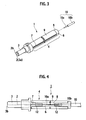
Fig. 3 is a perspective view of an optical connector according to an embodiment of the present invention. -
Fig. 4 is a side view of the optical connector shown inFig. 3 . -
Fig. 5 is a longitudinal cross-sectional view of the optical connector shown inFig. 3 . -
Fig. 6 is an exploded plan view of a main part of the optical connector shown inFig. 3 . -
Figs. 7A and 7B are views each showing a state in confirming an butt-connection state of optical fibers in the optical connector shown inFig. 3 ,Fig. 7A showing a state before the optical fibers abut on each other,Fig. 7B showing a state after the optical fibers abut on each other. -
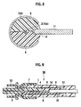
Fig. 8 is an enlarged cross-sectional view taken along the line A-A inFig. 7A (equivalent to a cross-sectional view taken along the line A-A inFig. 5 ). -
Fig. 9 is a cross-sectional view showing a state where the optical connector shown inFig. 3 is used. -
Fig. 10 is a longitudinal cross-sectional view of an optical connector according to an embodiment of the present invention. -
Fig. 11 is a transverse cross-sectional view of the optical connector shown inFig. 10 . - With reference to the drawings, description will be given below of a method and an apparatus for confirming optical fibers connection according to embodiments of the present invention.
- As shown in
Figs. 3 to 6 , anoptical connector 1 according to a first embodiment of the present invention includes: anoptical fiber 2; aferrule 3 having aconnection end face 3b where an end face of theoptical fiber 2 is exposed; and aconnection mechanism 4 extending from theferrule 3 in a direction opposite to theconnection end face 3b. Note that, as theoptical fiber 2 built in theoptical connector 1, an optical fiber formed of only a core and a cladding, a so-called bare optical fiber is preferable. - The
connection mechanism 4 includes: abase 6; covers 7 and 8 facing thebase 6; and aflat spring 9 formed into, for example, a C-shape or squared C-shape for elastically clamping thecovers base 6 is formed integrally with a cylindricalferrule fitting part 13 and a brim-shapedflange part 14. The ferrulefitting part 13 is fitted to theferrule 3. Thebase 6 extends from theflange part 14 in the direction opposite to theconnection end face 3b of theferrule 3. - As shown in
Fig. 6 , in thebase 6, apositioning groove 5 is formed, which is continuous with an opticalfiber insertion hole 3a in theferrule 3. Thepositioning groove 5 is constituted of apositioning groove 5a and apositioning groove 5b. Thepositioning groove 5a is formed so as to accommodate theoptical fiber 2 and anoptical fiber 10a which are butted and connected to each other. Thepositioning groove 5b is formed so as to accommodate asheath portion 10b of anoptical fiber 10 to be inserted into theoptical connector 1. - The
cover 7 is positioned so as to open and close a butt-connection part P of the optical fibers. In other words, thecover 7 is positioned so as to cover the butt-connection part P. Thecover 8 is positioned so as to open and close thesheath portion 10b of theoptical fiber 10. In other words, thecover 8 is positioned so as to cover thesheath portion 10b. Aninsertion member 11 is formed in a wedge shape and opens and closes thecovers base 6 against reaction force of theflat spring 9. In thebase 6 and thecovers concave parts 12 are formed, into which theinsertion member 11 is inserted when thebase 6 and thecovers insertion member 11 is used for installation of the optical connector. - The
optical connector 1 can also clamp thesheath portion 10b of theoptical fiber 10. Note that this optical connector is also called a Field-Installable Connector since field installation thereof is easy. - In installation of the
optical connector 1, first, theinsertion member 11 is inserted into theconcave parts 12 formed between thebase 6 and thecovers covers optical fiber 10 is inserted from the outside and then theoptical fiber 2 and the bareoptical fiber 10a of theoptical fiber 10 are allowed to abut on each other. Note that a tip of theoptical fiber 10 has its sheath previously peeled off and the bareoptical fiber 10a is exposed. Next, after connection is confirmed, theinsertion member 11 is removed and the butt-connection part P of the optical fibers as well as thesheath portion 10b of theoptical fiber 10 are sandwiched between thebase 6 and thecovers flat spring 9. Note that, as a drive mechanism of theinsertion member 11, drive mechanisms disclosed inPatent Document 1 andUS Patent No. 7346255 can be suitably used. This drive mechanism is also called a wedge unit. In this case, theinsertion member 11, as one of assembling tools, stably maintains an opened state between thebase 6 and thecovers - In this embodiment, the
insertion member 11 is made of a light transmissive material. However, as described later, the member made of the light transmissive material is not limited to theinsertion member 11. - As shown in
Fig. 6 , theinsertion member 11 integrally includeswedge parts wedge part 11a is used to open thecover 7. Thewedge part 11b is used to open thecover 8. Specifically, thewedge parts concave parts 12 defined between thebase 6 and thecovers -
Fig. 6 shows surfaces of therespective covers base 6. The surface of thecover 7 facing thebase 6 is flat. On the other hand, in the surface of thecover 8 facing thebase 6, thepositioning groove 5a configured to receive the bareoptical fiber 10a of theoptical fiber 10 and thepositioning groove 5b configured to receive thesheath portion 10b of theoptical fiber 10 are formed. - A refractive index matching material is injected on the end faces of the optical fibers.
- Next, the
insertion member 11 is removed and consequently theflat spring 9 urges thebase 6 and thecovers sheath portion 10b of theoptical fiber 10. - With reference to
Figs. 7A and 7B , description will be given of procedures for confirming whether or not theoptical fiber 2 and the bareoptical fiber 10a are properly butted and connected to each other in installation of theoptical connector 1. - As shown in
Fig. 7A , an apparatus for confirming connection of the optical fibers in the optical connector according to this embodiment of the present invention includes alight source 20, anoptical connector 22, an optical adapter (optical connector adapter) 40 and anoptical fiber 21. - As shown in
Fig. 7A , the optical fiber (first optical fiber) 21 has its one end connected to thelight source 20 and has the other end connected to theoptical connector 22. Theoptical fiber 21 may have a length at which a cladding mode caused by incident light disappears. The exemplary length thereof is 100cm to 200cm in consideration of operability and the like. The optical connector fits to theoptical connector 1 into which theoptical fiber 10a is not inserted yet. Theoptical adaptor 40 detachably holds theoptical connectors optical connectors optical connectors optical adaptor 40. - As the
optical fiber 21, an optical fiber which easily attenuates cladding mode light is preferably used. The optical fiber having such a characteristic is, for example, a standard single-mode optical fiber which is made of quartz glass. Moreover, theoptical fiber 21 is sheathed with, for example, resin or the like and a diameter thereof is, for example, 0.9 mm. Furthermore, theoptical fiber 21 may be bent to enhance attenuation of the cladding mode light, as long as light propagation is not disturbed. - Moreover, as the
light source 20, it is preferable to use a laser diode (LD) light source which emits light having a wavelength of 650 nm for optical communication or the like. - The light emitted from the
light source 20 passes through theoptical fiber 21 and enters theoptical fiber 2 in theoptical connector 1. In this state, the light that has entered theoptical fiber 2 exits from a whole area of the end face (core) of theoptical fiber 2. Since theinsertion member 11 is light transmissive, the light leaks to the outside of theoptical connector 1 through theinsertion member 11. This leak light has high intensity and theinsertion member 11 is visually observed to be considerably bright. - Note that the members that make up the optical connector other than the
insertion member 11 may be made of light transmissive resin or the like. In this case, the light can also be confirmed from those other members. - For example, when the members that make up the optical connector are made of a white resin, not only the light transmitted through the insertion member but also red light (wavelength of 650 nm) can be confirmed through the members made of the white resin.
- While the light from the
light source 20 passes through theoptical fiber 21, the cladding mode light is emitted from an outer surface of theoptical fiber 21 and mostly disappears around the connection between the optical connectors in theoptical adapter 40. Therefore, no or significantly attenuated cladding mode light enters theoptical fiber 2 and no or a very small amount of light is emitted from a peripheral surface of theoptical fiber 2. Note that the word "mostly" means that it is difficult to completely remove the cladding mode light and thus the cladding mode light that does not virtually affect brightness confirmation that is the object of the present invention may be left. This can be set as a definition of a term "disappearance of the cladding mode light" in the present invention. - Next, as shown in
Fig. 7B , theoptical fiber 10 is inserted into theoptical connector 1 and theoptical fiber 2 and the bareoptical fiber 10a are allowed to abut on each other. - In this case, when a butt-connection state is good, optical power propagated to the
optical fiber 2 from thelight source 20 is propagated to theoptical fiber 10a without leaking in the butt-connection part P. Therefore, leakage of the optical power to the outside of theoptical connector 1 is very small. - Specifically, as described above, no or significantly attenuated cladding mode light enters the
optical fiber 2 and most of the optical power exists in the core. Moreover, no or a very small amount of light is emitted from the peripheral surface of theoptical fiber 2 that is the bare optical fiber. - Therefore, in the butt-connection part P, there is almost no light (that is background light) other than the leak light from the
optical fiber 2. When the butt-connection state of theoptical fiber 2 and the bareoptical fiber 10a is good, theinsertion member 11 is visually observed to be dark (note that the observation focuses on thewedge part 11a). - When it can be confirmed that the butt-connection state is good, the
insertion member 11 is pulled out, and thebase 6 and thecovers base 6 in theconnection mechanism 4 are closed. Moreover, an urging force of theflat spring 9 mechanically fixes the part between theoptical fiber 2 and the bareoptical fiber 10a and the vicinity thereof. - Meanwhile, the butt-connection state is considered to be bad in any one of the following states: the bare
optical fiber 10a is not sufficiently pressed against theoptical fiber 2; there is a gap between the end faces of the optical fibers; and any of the end faces of the optical fibers is in bad condition. - When the connection state is bad, the light from the
optical fiber 2 leaks from the butt-connection part P. Thus, the light leaks to the outside of theoptical connector 1 through theinsertion member 11. Therefore, since theinsertion member 11 is observed to be bright, the bad butt-connection state of theoptical fiber 2 and the bareoptical fiber 10a can be confirmed. - In this case, considering that there is almost no background light in the butt-connection part P, there is a significantly large difference in light intensity observed between the good and bad butt-connection states. Therefore, it is possible to clearly confirm whether the butt-connection state is good or bad even in a bright environment.
- The
insertion member 11 described above integrally includes the twowedge parts wedge parts wedge part 11a is made of a transparent material. -
Fig. 9 shows an example of anoptical connector apparatus 50 using theoptical connector 1. Theoptical connector apparatus 50 includes aspring 51, astop ring 52 and ahousing 53 in addition to theoptical connector 1. Thespring 51 is disposed on a rear end face of theconnection mechanism 4 so as to allow theoptical fiber 10 to be inserted thereinto. Thestop ring 52 is placed over theoptical connector 1 from behind theoptical connector 1 in a state where thespring 51 is disposed. Therefore, theoptical connector 1 is urged forward (in other words, toward the ferrule 3) by thespring 51. Furthermore, thehousing 53 is placed over theferrule 3 and a front portion of theconnection mechanism 4. - The
optical connector apparatus 50 is detachably held by theoptical adapter 40, for example, or the like and is connected to another optical connector in the adapter. - When an assembling tool (opening member) integrally including an insertion member is used as in the case of
US Patent No. 7346255 , a butt-connection state can also be confirmed in a state where theoptical connector 1 is housed in theoptical connector apparatus 50. In this case, a slit (not shown) which allows an opening and closing member to pass therethrough is provided in thehousing 53. -
Fig. 10 is a longitudinal cross-sectional view of an optical connector according to a second embodiment of the present invention. Anoptical connector 31 of this embodiment has a connection mechanism configured to mechanically butt and connect twooptical fibers 10 to each other. This connection mechanism is called a mechanical splice. Theoptical connector 31 includes: a base 36 having a positioninggroove 35 formed therein; acover 37 and covers 38 which are all facing thebase 36; and a C-shaped or squared C-shapedflat spring 39 for elastically clamping thebase 36 and thecovers positioning groove 35 is constituted of apositioning groove 35a and apositioning groove 35b. In thepositioning groove 35b, theoptical fiber 10 is disposed. In thepositioning groove 35a, a bareoptical fiber 10a is disposed, which is exposed by peeling off a sheath of theoptical fiber 10. - The
cover 37 is disposed between thecovers 38. Thecover 37 opens and closes a butt-connection part P of the bareoptical fibers 10a. Thecovers 38 are disposed respectively on the two sides of thecover 37, and each open and close a portion in which asheath portion 10b of the correspondingoptical fiber 10 is disposed, thesheath portion 10b being inserted from a corresponding side of theoptical connector 31. - As shown in
Fig. 11 , aninsertion member 41 is inserted so as to open and close a portion between the base 36 and thecovers insertion member 41 is made of a light transmissive material. - Procedures for confirming a butt-connection state of the
optical fiber 10a in installation of theoptical connector 31 are basically the same as those described in the first embodiment. Leak light from the butt-connection part P is detected through theinsertion member 41. - In both of the embodiments described above, the
insertion member 11 is made of a light transmissive material, and the leak light from theinsertion member 11 is detected to confirm the butt-connection state. However, as described above, the leak light is not necessarily limited to that from theinsertion member 11. - For example, in the first embodiment, at least one of the
base 6 and thecover 7 in theconnection mechanism 4 is made of the light transmissive material and leak light from the butt-connection part P can be observed therefrom. Such an observation can be implemented in the second embodiment by forming at least one of thebase 36 and thecovers 38 of the light transmissive material. Specifically, the present invention can be applied to an optical connector which has a portion configured to communicate leak light to the outside or which has at least a part thereof formed of an optically transparent material allowing transmission of the leak light. - Moreover, in the above embodiment, the light source of 650 nm is used to visually observe the light intensity of the leak light as bright and dark. The light intensity can also be detected by a light intensity meter. In the case of using the light intensity meter, the light to be detected is not limited to visible light.
- Moreover, in the present invention, a quartz optical fiber can be applied as the optical fiber. Furthermore, a surface of the optical fiber may be sheathed with a polyvinyl chloride resin and the like to improve mechanical strength. In the first embodiment, in particular, the
optical fiber 21 connecting thelight source 20 to theoptical connector 22 may have its periphery reinforced with a tensile fiber. - According to the method and apparatus for confirming optical fibers connection according to the present invention, the optical fiber interposed between the optical connector and the light source attenuates cladding mode light. Specifically, while the light from the light source passes through the optical fiber, the cladding mode light is emitted from cladding to the outside. Thus, the cladding mode light does not reach the inside of the optical connector or is significantly attenuated.
- Therefore, in the abutting part of the optical fibers in the optical connector, the leak light from the cladding is significantly reduced. When the butt-connection state is good, loss of optical power transmitted from a core of one optical fiber to a core of the other optical fiber and light reflection are significantly reduced. Accordingly, leak light from an abutting end face of the optical fibers is significantly reduced. Thus, a difference in light intensity in the butt-connection part between good and bad butt-connection states is relatively increased. Consequently, it becomes possible to clearly confirm the butt-connection state even in a bright environment during the day.
Claims (14)
- A method for confirming optical fibers connection in a connection part in an optical connector, comprising:allowing light to pass through a first optical fiber while causing cladding mode light to disappear; anddetecting a difference in light intensity in the connection part between before and after the light from the first optical fiber enters a second optical fiber disposed in the optical connector.
- The method according to claim 1, wherein the first optical fiber is bent when light passes therethrough.
- The method according to claim 2, wherein a wavelength of light entering the first optical fiber is 650 nm, and a length of the first optical fiber is 100 cm to 200 cm.
- The method according to claim 3, wherein the first optical fiber is a single-mode optical fiber.
- The method according to claim 1, wherein
the difference in light intensity is detected through a light transmissive member located in the connection part. - The method according to claim 5, wherein
the optical connector includes a ferrule and a third optical fiber inserted into the ferrule, and
light that exits from the first optical fiber enters the second optical fiber through the third optical fiber. - The method according to claim 6, wherein
the optical connector has a connection mechanism extending in a direction opposite to that toward a connection end face of the ferrule,
the connection mechanism includesa base,first and second covers openably and closably facing the base and a flat spring for elastically clamping the base and all the covers,a positioning groove for the optical fiber is formed in the base,
the first cover is located so as to open and close the connection part,
the second cover is located so as to cover a sheath portion of the second optical fiber, and
the light transmissive member is an insertion member and is inserted between the base and the first and second covers so as to open and close the base and the covers. - The method according to claim 6, wherein
the optical connector has a connection mechanism extending in a direction opposite to that toward a connection end face of the ferrule,
the connection mechanism includesa base,first and second covers openably and closably facing the base anda flat spring for elastically clamping the base and all the covers,the light transmissive member is at least one of the base and the first cover,
a positioning groove for the optical fiber is formed in the base,
the first cover is located so as to open and close the connection part, and
the second cover is located so as to cover a sheath portion of the second optical fiber. - The method according to claim 5, wherein
the optical connector includesa base,first, second, and third covers openably and closably facing the base anda flat spring for elastically clamping the base and all the covers,a positioning groove for the optical fiber is formed in the base,
the first cover is located so as to open and close the connection part,
the second cover is located so as to cover a sheath portion of the first optical fiber,
the third cover is located so as to cover a sheath portion of the second optical fiber, and
the light transmissive member is an insertion member and is inserted between the base and the first to third covers so as to open and close the base and the first, second and third covers. - The method according to claim 5, wherein
the optical connector includesa base,first, second, and third covers openably and closably facing the base anda flat spring for elastically clamping the base and all the covers,a positioning groove for the optical fiber is formed in the base,
the first cover is located so as to open and close the connection part,
the second cover is located so as to cover a sheath portion of the first optical fiber,
the third cover is located so as to cover a sheath portion of the second optical fiber, and
the light transmissive member is the base and the first cover. - An apparatus for confirming optical fibers connection in an optical connector, comprising:a light source;an optical connector;an optical adapter configured to detachably hold the optical connector and another optical connector and to connect the optical connectors to each other; andan optical fiber connecting the light source to the optical connector,wherein the optical fiber has a length enough to cause cladding mode light generated by light from the light source to disappear.
- The apparatus according to claim 11, wherein
the optical fiber is bent so as to enhance attenuation of the cladding mode light. - The apparatus according to claim 12, wherein
the light source is a laser diode which emits light having a wavelength of 650 nm, and
the length of the optical fiber is 100 cm to 200 cm. - The apparatus according to claim 13, wherein the optical fiber is a single-mode optical fiber.
Applications Claiming Priority (1)
| Application Number | Priority Date | Filing Date | Title |
|---|---|---|---|
| JP2008165009 | 2008-06-24 |
Publications (2)
| Publication Number | Publication Date |
|---|---|
| EP2138879A1 true EP2138879A1 (en) | 2009-12-30 |
| EP2138879B1 EP2138879B1 (en) | 2015-05-06 |
Family
ID=41037862
Family Applications (1)
| Application Number | Title | Priority Date | Filing Date |
|---|---|---|---|
| EP20090163184 Active EP2138879B1 (en) | 2008-06-24 | 2009-06-19 | Method and apparatus for confirming optical fibers connection in optical connector |
Country Status (4)
| Country | Link |
|---|---|
| US (2) | US8111956B2 (en) |
| EP (1) | EP2138879B1 (en) |
| JP (1) | JP5164271B2 (en) |
| CN (1) | CN101614845B (en) |
Families Citing this family (10)
| Publication number | Priority date | Publication date | Assignee | Title |
|---|---|---|---|---|
| CN102308237A (en) * | 2009-02-12 | 2012-01-04 | 株式会社藤仓 | Optical connector |
| JP5594083B2 (en) * | 2010-11-19 | 2014-09-24 | ソニー株式会社 | Optical fiber adapter and laser device |
| JP5677182B2 (en) * | 2011-04-26 | 2015-02-25 | 株式会社フジクラ | Optical connector |
| US8981961B2 (en) | 2013-01-21 | 2015-03-17 | International Business Machines Corporation | Validation of mechanical connections |
| EP3080650A1 (en) * | 2013-12-09 | 2016-10-19 | Koninklijke Philips N.V. | Optical fiber connector validation |
| JP6057940B2 (en) * | 2014-04-01 | 2017-01-11 | 株式会社フジクラ | Optical fiber connector |
| JP6187691B2 (en) * | 2014-06-12 | 2017-08-30 | 株式会社島津製作所 | Fiber coupling module |
| EP4425153A3 (en) | 2015-06-12 | 2024-11-20 | Pacific Biosciences Of California, Inc. | Integrated target waveguide devices and systems for optical coupling |
| CN110361817A (en) * | 2019-08-20 | 2019-10-22 | 江苏宇特光电科技股份有限公司 | Optical fiber docking detection method and device applied to optical fiber connector |
| AU2021222009A1 (en) | 2020-02-18 | 2022-09-15 | Pacific Biosciences Of California, Inc. | Highly multiplexed nucleic acid sequencing systems |
Citations (5)
| Publication number | Priority date | Publication date | Assignee | Title |
|---|---|---|---|---|
| EP0846965B1 (en) * | 1995-08-24 | 2002-03-13 | Fujikura Ltd. | Optical fiber connector |
| JP2005292429A (en) * | 2004-03-31 | 2005-10-20 | Fujikura Ltd | Optical fiber connection opening member, optical fiber connection tool, optical connector, optical fiber connector and optical fiber butt connection confirmation method |
| WO2007078551A2 (en) | 2005-12-15 | 2007-07-12 | Corning Cable Systems Llc | Apparatus and methods for verifying an acceptable splice termination |
| JP2007225961A (en) | 2006-02-24 | 2007-09-06 | Nippon Telegr & Teleph Corp <Ntt> | Optical fiber connection method |
| US7346255B2 (en) | 2004-11-15 | 2008-03-18 | Fujikura Ltd. | Tool for optical connector and tool equipped optical connector |
Family Cites Families (17)
| Publication number | Priority date | Publication date | Assignee | Title |
|---|---|---|---|---|
| GB8706929D0 (en) * | 1987-03-24 | 1987-04-29 | British Telecomm | Optical coupling device |
| JPH03269505A (en) * | 1990-03-20 | 1991-12-02 | Mitsubishi Electric Corp | Optical fiber connector |
| JPH05226759A (en) * | 1992-02-10 | 1993-09-03 | Sumitomo Electric Ind Ltd | Light source for light measurement |
| US5367594A (en) * | 1992-09-01 | 1994-11-22 | The Whitaker Corporation | Fiber optic splicer-connector |
| US5278932A (en) * | 1992-09-30 | 1994-01-11 | At&T Bell Laboratories | Optical fiber splice verification system |
| JP3768278B2 (en) * | 1996-01-17 | 2006-04-19 | 株式会社フジクラ | Optical fiber connector and optical fiber connection method |
| JPH1078526A (en) * | 1996-05-09 | 1998-03-24 | Daewoo Telecommun Ltd | Splicer for optical waveguide |
| JP3602339B2 (en) * | 1997-06-16 | 2004-12-15 | 株式会社フジクラ | Optical connector |
| US6810178B2 (en) * | 1998-12-04 | 2004-10-26 | Cidra Corporation | Large diameter optical waveguide having blazed grating therein |
| US7467896B2 (en) * | 2000-05-26 | 2008-12-23 | Corning Cable Systems Llc | Fiber optic drop cables and preconnectorized assemblies |
| US7104702B2 (en) * | 2004-03-24 | 2006-09-12 | Corning Cable Systems Llc | Field installable optical fiber connector |
| JP4083696B2 (en) | 2004-03-30 | 2008-04-30 | 株式会社フジクラ | Optical connector, optical connector assembly method |
| JP4657205B2 (en) * | 2004-04-22 | 2011-03-23 | 富士通株式会社 | Optical fiber connection structure |
| US7264401B2 (en) * | 2004-05-28 | 2007-09-04 | Corning Cable Systems Llc | Panel-mountable optical fiber splice |
| WO2007050470A1 (en) * | 2005-10-24 | 2007-05-03 | 3M Innovative Properties Company | Optical connector, fiber distribution unit, and fiber termination platform for optical connectors |
| US7539381B2 (en) * | 2007-05-11 | 2009-05-26 | Corning Incorporated | Low bend loss coated optical fiber |
| WO2009146367A1 (en) * | 2008-05-29 | 2009-12-03 | Panduit Corp. | Method and apparatus for verifying the termination quality of an optical fiber interface in a fiber optic cable connector |
-
2009
- 2009-06-18 JP JP2009145881A patent/JP5164271B2/en active Active
- 2009-06-19 EP EP20090163184 patent/EP2138879B1/en active Active
- 2009-06-22 US US12/488,832 patent/US8111956B2/en active Active
- 2009-06-24 CN CN200910139497.4A patent/CN101614845B/en active Active
-
2011
- 2011-12-22 US US13/335,160 patent/US20120163753A1/en not_active Abandoned
Patent Citations (5)
| Publication number | Priority date | Publication date | Assignee | Title |
|---|---|---|---|---|
| EP0846965B1 (en) * | 1995-08-24 | 2002-03-13 | Fujikura Ltd. | Optical fiber connector |
| JP2005292429A (en) * | 2004-03-31 | 2005-10-20 | Fujikura Ltd | Optical fiber connection opening member, optical fiber connection tool, optical connector, optical fiber connector and optical fiber butt connection confirmation method |
| US7346255B2 (en) | 2004-11-15 | 2008-03-18 | Fujikura Ltd. | Tool for optical connector and tool equipped optical connector |
| WO2007078551A2 (en) | 2005-12-15 | 2007-07-12 | Corning Cable Systems Llc | Apparatus and methods for verifying an acceptable splice termination |
| JP2007225961A (en) | 2006-02-24 | 2007-09-06 | Nippon Telegr & Teleph Corp <Ntt> | Optical fiber connection method |
Also Published As
| Publication number | Publication date |
|---|---|
| JP5164271B2 (en) | 2013-03-21 |
| EP2138879B1 (en) | 2015-05-06 |
| JP2010033039A (en) | 2010-02-12 |
| US20120163753A1 (en) | 2012-06-28 |
| CN101614845B (en) | 2014-09-24 |
| US20090317074A1 (en) | 2009-12-24 |
| US8111956B2 (en) | 2012-02-07 |
| CN101614845A (en) | 2009-12-30 |
Similar Documents
| Publication | Publication Date | Title |
|---|---|---|
| US8111956B2 (en) | Method and apparatus for confirming optical fibers connection in optical connector | |
| CA2635563C (en) | Splice connector for verifying an acceptable splice termination | |
| CN100501473C (en) | On-site installable optical fiber connector | |
| JP5710481B2 (en) | Optical fiber adapter with integrated shutter | |
| USRE46270E1 (en) | Optical fiber connector and associated methods of validating optical fiber continuity | |
| CN100533191C (en) | Optical connector and method of assembling optical connector | |
| CN101937117A (en) | optical connector | |
| WO2004092795A1 (en) | Optical connector and housing for optical connector | |
| CN103026277A (en) | Optical connector and method for assembling same | |
| JP4347115B2 (en) | Optical fiber connection opening member, optical connector, optical fiber connector and optical fiber butt connection confirmation method | |
| JP4832401B2 (en) | Optical connector adapter | |
| JP5342262B2 (en) | Optical connector | |
| JP6684461B2 (en) | Optical visualization filter and communication optical visualization device using the same | |
| JP2013015787A (en) | Optical connector and assembling method of the same | |
| JP4684182B2 (en) | Optical connector | |
| JP5436148B2 (en) | Optical connector | |
| JPH10300985A (en) | Multi-core optical connector | |
| JP2012088437A (en) | Optical fiber splicer | |
| JP2010211074A (en) | Optical connector and assembling wedge | |
| JP2007240867A (en) | Optical connector | |
| JP2008145855A (en) | Structure and method of connecting optical fibers | |
| JPH11305045A (en) | Optical connector | |
| HK1141088A1 (en) | Optical fiber connector and optical cable |
Legal Events
| Date | Code | Title | Description |
|---|---|---|---|
| PUAI | Public reference made under article 153(3) epc to a published international application that has entered the european phase |
Free format text: ORIGINAL CODE: 0009012 |
|
| AK | Designated contracting states |
Kind code of ref document: A1 Designated state(s): AT BE BG CH CY CZ DE DK EE ES FI FR GB GR HR HU IE IS IT LI LT LU LV MC MK MT NL NO PL PT RO SE SI SK TR |
|
| 17P | Request for examination filed |
Effective date: 20100409 |
|
| 17Q | First examination report despatched |
Effective date: 20100531 |
|
| GRAP | Despatch of communication of intention to grant a patent |
Free format text: ORIGINAL CODE: EPIDOSNIGR1 |
|
| INTG | Intention to grant announced |
Effective date: 20141114 |
|
| GRAS | Grant fee paid |
Free format text: ORIGINAL CODE: EPIDOSNIGR3 |
|
| GRAA | (expected) grant |
Free format text: ORIGINAL CODE: 0009210 |
|
| AK | Designated contracting states |
Kind code of ref document: B1 Designated state(s): AT BE BG CH CY CZ DE DK EE ES FI FR GB GR HR HU IE IS IT LI LT LU LV MC MK MT NL NO PL PT RO SE SI SK TR |
|
| REG | Reference to a national code |
Ref country code: GB Ref legal event code: FG4D |
|
| REG | Reference to a national code |
Ref country code: CH Ref legal event code: EP |
|
| REG | Reference to a national code |
Ref country code: IE Ref legal event code: FG4D |
|
| REG | Reference to a national code |
Ref country code: AT Ref legal event code: REF Ref document number: 726104 Country of ref document: AT Kind code of ref document: T Effective date: 20150615 |
|
| REG | Reference to a national code |
Ref country code: DE Ref legal event code: R096 Ref document number: 602009031044 Country of ref document: DE Effective date: 20150618 |
|
| REG | Reference to a national code |
Ref country code: AT Ref legal event code: MK05 Ref document number: 726104 Country of ref document: AT Kind code of ref document: T Effective date: 20150506 |
|
| REG | Reference to a national code |
Ref country code: NL Ref legal event code: MP Effective date: 20150506 |
|
| REG | Reference to a national code |
Ref country code: LT Ref legal event code: MG4D |
|
| PG25 | Lapsed in a contracting state [announced via postgrant information from national office to epo] |
Ref country code: FI Free format text: LAPSE BECAUSE OF FAILURE TO SUBMIT A TRANSLATION OF THE DESCRIPTION OR TO PAY THE FEE WITHIN THE PRESCRIBED TIME-LIMIT Effective date: 20150506 Ref country code: NO Free format text: LAPSE BECAUSE OF FAILURE TO SUBMIT A TRANSLATION OF THE DESCRIPTION OR TO PAY THE FEE WITHIN THE PRESCRIBED TIME-LIMIT Effective date: 20150806 Ref country code: ES Free format text: LAPSE BECAUSE OF FAILURE TO SUBMIT A TRANSLATION OF THE DESCRIPTION OR TO PAY THE FEE WITHIN THE PRESCRIBED TIME-LIMIT Effective date: 20150506 Ref country code: PT Free format text: LAPSE BECAUSE OF FAILURE TO SUBMIT A TRANSLATION OF THE DESCRIPTION OR TO PAY THE FEE WITHIN THE PRESCRIBED TIME-LIMIT Effective date: 20150907 Ref country code: LT Free format text: LAPSE BECAUSE OF FAILURE TO SUBMIT A TRANSLATION OF THE DESCRIPTION OR TO PAY THE FEE WITHIN THE PRESCRIBED TIME-LIMIT Effective date: 20150506 Ref country code: HR Free format text: LAPSE BECAUSE OF FAILURE TO SUBMIT A TRANSLATION OF THE DESCRIPTION OR TO PAY THE FEE WITHIN THE PRESCRIBED TIME-LIMIT Effective date: 20150506 |
|
| PG25 | Lapsed in a contracting state [announced via postgrant information from national office to epo] |
Ref country code: AT Free format text: LAPSE BECAUSE OF FAILURE TO SUBMIT A TRANSLATION OF THE DESCRIPTION OR TO PAY THE FEE WITHIN THE PRESCRIBED TIME-LIMIT Effective date: 20150506 Ref country code: IS Free format text: LAPSE BECAUSE OF FAILURE TO SUBMIT A TRANSLATION OF THE DESCRIPTION OR TO PAY THE FEE WITHIN THE PRESCRIBED TIME-LIMIT Effective date: 20150906 Ref country code: BG Free format text: LAPSE BECAUSE OF FAILURE TO SUBMIT A TRANSLATION OF THE DESCRIPTION OR TO PAY THE FEE WITHIN THE PRESCRIBED TIME-LIMIT Effective date: 20150806 Ref country code: LV Free format text: LAPSE BECAUSE OF FAILURE TO SUBMIT A TRANSLATION OF THE DESCRIPTION OR TO PAY THE FEE WITHIN THE PRESCRIBED TIME-LIMIT Effective date: 20150506 Ref country code: GR Free format text: LAPSE BECAUSE OF FAILURE TO SUBMIT A TRANSLATION OF THE DESCRIPTION OR TO PAY THE FEE WITHIN THE PRESCRIBED TIME-LIMIT Effective date: 20150807 |
|
| REG | Reference to a national code |
Ref country code: DE Ref legal event code: R119 Ref document number: 602009031044 Country of ref document: DE |
|
| PG25 | Lapsed in a contracting state [announced via postgrant information from national office to epo] |
Ref country code: IT Free format text: LAPSE BECAUSE OF NON-PAYMENT OF DUE FEES Effective date: 20150619 Ref country code: EE Free format text: LAPSE BECAUSE OF FAILURE TO SUBMIT A TRANSLATION OF THE DESCRIPTION OR TO PAY THE FEE WITHIN THE PRESCRIBED TIME-LIMIT Effective date: 20150506 Ref country code: DK Free format text: LAPSE BECAUSE OF FAILURE TO SUBMIT A TRANSLATION OF THE DESCRIPTION OR TO PAY THE FEE WITHIN THE PRESCRIBED TIME-LIMIT Effective date: 20150506 |
|
| REG | Reference to a national code |
Ref country code: CH Ref legal event code: PL |
|
| PG25 | Lapsed in a contracting state [announced via postgrant information from national office to epo] |
Ref country code: PL Free format text: LAPSE BECAUSE OF FAILURE TO SUBMIT A TRANSLATION OF THE DESCRIPTION OR TO PAY THE FEE WITHIN THE PRESCRIBED TIME-LIMIT Effective date: 20150506 Ref country code: MC Free format text: LAPSE BECAUSE OF FAILURE TO SUBMIT A TRANSLATION OF THE DESCRIPTION OR TO PAY THE FEE WITHIN THE PRESCRIBED TIME-LIMIT Effective date: 20150506 Ref country code: SK Free format text: LAPSE BECAUSE OF FAILURE TO SUBMIT A TRANSLATION OF THE DESCRIPTION OR TO PAY THE FEE WITHIN THE PRESCRIBED TIME-LIMIT Effective date: 20150506 Ref country code: CZ Free format text: LAPSE BECAUSE OF FAILURE TO SUBMIT A TRANSLATION OF THE DESCRIPTION OR TO PAY THE FEE WITHIN THE PRESCRIBED TIME-LIMIT Effective date: 20150506 Ref country code: RO Free format text: LAPSE BECAUSE OF NON-PAYMENT OF DUE FEES Effective date: 20150506 |
|
| PLBE | No opposition filed within time limit |
Free format text: ORIGINAL CODE: 0009261 |
|
| STAA | Information on the status of an ep patent application or granted ep patent |
Free format text: STATUS: NO OPPOSITION FILED WITHIN TIME LIMIT |
|
| REG | Reference to a national code |
Ref country code: IE Ref legal event code: MM4A |
|
| REG | Reference to a national code |
Ref country code: FR Ref legal event code: ST Effective date: 20160229 |
|
| 26N | No opposition filed |
Effective date: 20160209 |
|
| PG25 | Lapsed in a contracting state [announced via postgrant information from national office to epo] |
Ref country code: LI Free format text: LAPSE BECAUSE OF NON-PAYMENT OF DUE FEES Effective date: 20150630 Ref country code: DE Free format text: LAPSE BECAUSE OF NON-PAYMENT OF DUE FEES Effective date: 20160101 Ref country code: IE Free format text: LAPSE BECAUSE OF NON-PAYMENT OF DUE FEES Effective date: 20150619 Ref country code: CH Free format text: LAPSE BECAUSE OF NON-PAYMENT OF DUE FEES Effective date: 20150630 |
|
| PGRI | Patent reinstated in contracting state [announced from national office to epo] |
Ref country code: IT Effective date: 20160412 |
|
| PG25 | Lapsed in a contracting state [announced via postgrant information from national office to epo] |
Ref country code: FR Free format text: LAPSE BECAUSE OF NON-PAYMENT OF DUE FEES Effective date: 20150706 Ref country code: SI Free format text: LAPSE BECAUSE OF FAILURE TO SUBMIT A TRANSLATION OF THE DESCRIPTION OR TO PAY THE FEE WITHIN THE PRESCRIBED TIME-LIMIT Effective date: 20150506 |
|
| PG25 | Lapsed in a contracting state [announced via postgrant information from national office to epo] |
Ref country code: BE Free format text: LAPSE BECAUSE OF FAILURE TO SUBMIT A TRANSLATION OF THE DESCRIPTION OR TO PAY THE FEE WITHIN THE PRESCRIBED TIME-LIMIT Effective date: 20150506 |
|
| PG25 | Lapsed in a contracting state [announced via postgrant information from national office to epo] |
Ref country code: MT Free format text: LAPSE BECAUSE OF FAILURE TO SUBMIT A TRANSLATION OF THE DESCRIPTION OR TO PAY THE FEE WITHIN THE PRESCRIBED TIME-LIMIT Effective date: 20150506 |
|
| PG25 | Lapsed in a contracting state [announced via postgrant information from national office to epo] |
Ref country code: HU Free format text: LAPSE BECAUSE OF FAILURE TO SUBMIT A TRANSLATION OF THE DESCRIPTION OR TO PAY THE FEE WITHIN THE PRESCRIBED TIME-LIMIT; INVALID AB INITIO Effective date: 20090619 |
|
| PG25 | Lapsed in a contracting state [announced via postgrant information from national office to epo] |
Ref country code: NL Free format text: LAPSE BECAUSE OF FAILURE TO SUBMIT A TRANSLATION OF THE DESCRIPTION OR TO PAY THE FEE WITHIN THE PRESCRIBED TIME-LIMIT Effective date: 20150506 Ref country code: CY Free format text: LAPSE BECAUSE OF FAILURE TO SUBMIT A TRANSLATION OF THE DESCRIPTION OR TO PAY THE FEE WITHIN THE PRESCRIBED TIME-LIMIT Effective date: 20150506 Ref country code: SE Free format text: LAPSE BECAUSE OF FAILURE TO SUBMIT A TRANSLATION OF THE DESCRIPTION OR TO PAY THE FEE WITHIN THE PRESCRIBED TIME-LIMIT Effective date: 20150506 |
|
| PG25 | Lapsed in a contracting state [announced via postgrant information from national office to epo] |
Ref country code: LU Free format text: LAPSE BECAUSE OF NON-PAYMENT OF DUE FEES Effective date: 20150619 |
|
| PG25 | Lapsed in a contracting state [announced via postgrant information from national office to epo] |
Ref country code: MK Free format text: LAPSE BECAUSE OF FAILURE TO SUBMIT A TRANSLATION OF THE DESCRIPTION OR TO PAY THE FEE WITHIN THE PRESCRIBED TIME-LIMIT Effective date: 20150506 |
|
| PGFP | Annual fee paid to national office [announced via postgrant information from national office to epo] |
Ref country code: TR Payment date: 20200619 Year of fee payment: 12 |
|
| PG25 | Lapsed in a contracting state [announced via postgrant information from national office to epo] |
Ref country code: TR Free format text: LAPSE BECAUSE OF NON-PAYMENT OF DUE FEES Effective date: 20210619 |
|
| PGFP | Annual fee paid to national office [announced via postgrant information from national office to epo] |
Ref country code: GB Payment date: 20250501 Year of fee payment: 17 |
|
| PGFP | Annual fee paid to national office [announced via postgrant information from national office to epo] |
Ref country code: IT Payment date: 20250522 Year of fee payment: 17 |