EP2138778A1 - Cooling/heating panel - Google Patents
Cooling/heating panel Download PDFInfo
- Publication number
- EP2138778A1 EP2138778A1 EP08740356A EP08740356A EP2138778A1 EP 2138778 A1 EP2138778 A1 EP 2138778A1 EP 08740356 A EP08740356 A EP 08740356A EP 08740356 A EP08740356 A EP 08740356A EP 2138778 A1 EP2138778 A1 EP 2138778A1
- Authority
- EP
- European Patent Office
- Prior art keywords
- heat exchange
- exchange pipe
- cooling
- soaking plate
- holding
- Prior art date
- Legal status (The legal status is an assumption and is not a legal conclusion. Google has not performed a legal analysis and makes no representation as to the accuracy of the status listed.)
- Withdrawn
Links
Images



Classifications
-
- F—MECHANICAL ENGINEERING; LIGHTING; HEATING; WEAPONS; BLASTING
- F24—HEATING; RANGES; VENTILATING
- F24F—AIR-CONDITIONING; AIR-HUMIDIFICATION; VENTILATION; USE OF AIR CURRENTS FOR SCREENING
- F24F5/00—Air-conditioning systems or apparatus not covered by F24F1/00 or F24F3/00, e.g. using solar heat or combined with household units such as an oven or water heater
- F24F5/0089—Systems using radiation from walls or panels
-
- F—MECHANICAL ENGINEERING; LIGHTING; HEATING; WEAPONS; BLASTING
- F24—HEATING; RANGES; VENTILATING
- F24D—DOMESTIC- OR SPACE-HEATING SYSTEMS, e.g. CENTRAL HEATING SYSTEMS; DOMESTIC HOT-WATER SUPPLY SYSTEMS; ELEMENTS OR COMPONENTS THEREFOR
- F24D3/00—Hot-water central heating systems
- F24D3/12—Tube and panel arrangements for ceiling, wall, or underfloor heating
- F24D3/14—Tube and panel arrangements for ceiling, wall, or underfloor heating incorporated in a ceiling, wall or floor
- F24D3/146—Tubes specially adapted for underfloor heating
-
- F—MECHANICAL ENGINEERING; LIGHTING; HEATING; WEAPONS; BLASTING
- F24—HEATING; RANGES; VENTILATING
- F24D—DOMESTIC- OR SPACE-HEATING SYSTEMS, e.g. CENTRAL HEATING SYSTEMS; DOMESTIC HOT-WATER SUPPLY SYSTEMS; ELEMENTS OR COMPONENTS THEREFOR
- F24D3/00—Hot-water central heating systems
- F24D3/12—Tube and panel arrangements for ceiling, wall, or underfloor heating
- F24D3/16—Tube and panel arrangements for ceiling, wall, or underfloor heating mounted on, or adjacent to, a ceiling, wall or floor
- F24D3/165—Suspended radiant heating ceiling
-
- F—MECHANICAL ENGINEERING; LIGHTING; HEATING; WEAPONS; BLASTING
- F24—HEATING; RANGES; VENTILATING
- F24F—AIR-CONDITIONING; AIR-HUMIDIFICATION; VENTILATION; USE OF AIR CURRENTS FOR SCREENING
- F24F5/00—Air-conditioning systems or apparatus not covered by F24F1/00 or F24F3/00, e.g. using solar heat or combined with household units such as an oven or water heater
- F24F5/0089—Systems using radiation from walls or panels
- F24F5/0092—Systems using radiation from walls or panels ceilings, e.g. cool ceilings
-
- Y—GENERAL TAGGING OF NEW TECHNOLOGICAL DEVELOPMENTS; GENERAL TAGGING OF CROSS-SECTIONAL TECHNOLOGIES SPANNING OVER SEVERAL SECTIONS OF THE IPC; TECHNICAL SUBJECTS COVERED BY FORMER USPC CROSS-REFERENCE ART COLLECTIONS [XRACs] AND DIGESTS
- Y02—TECHNOLOGIES OR APPLICATIONS FOR MITIGATION OR ADAPTATION AGAINST CLIMATE CHANGE
- Y02B—CLIMATE CHANGE MITIGATION TECHNOLOGIES RELATED TO BUILDINGS, e.g. HOUSING, HOUSE APPLIANCES OR RELATED END-USER APPLICATIONS
- Y02B30/00—Energy efficient heating, ventilation or air conditioning [HVAC]
Definitions
- the present invention relates to a cooling/heating panel which performs interior cooling or heating by means of radiation heat obtained by heat exchange via a fluid.
- a radiation-type cooling/heating panel constructed on ceiling has been known.
- Such a cooling/heating panel has a radiation panel made of a metal or a plaster board; a metallic or resin heat exchange pipe is disposed at a backside of the radiation panel; and this cooling/heating panel is installed on a ceiling.
- a fluid of a predetermined temperature is flowed in the heat exchange pipe installed on the ceiling, and interior cooling/heating is performed.
- a ceiling cooling/heating panel having a metallic pipe like a ceiling element disclosed in Patent Document 1, there is the one in which a metallic heat exchange pipe such as copper is mounted on a backside of a ceiling cooling/heating panel.
- the metallic heat exchange pipe per se has appropriate thermal conductivity; and has high gas barrier properties, so that oxygen does not permeate, or alternatively, circuit components or the like of a connecting portion do not corrode.
- the resin heat exchange pipe has a feature that it is well workable, is lightweight, and is low in cost, whereas its thermal conductivity is low in comparison with that of the metallic heat exchange pipe. Therefore, like a ceiling radiation cooling/heating panel disclosed in Patent Document 2, there is proposed the one having a structure in which: a heat exchange pipe is covered with a metallic soaking plate and the heat exchange pipe is held between the soaking plate and a backside of a radiation panel. In this manner, a heat from the heat exchange pipe is efficiently transmitted to the radiation panel.
- the resin heat exchange pipe has entailed a problem that: gas barrier properties are poor; oxygen contained in air enters a heat exchange medium passing through the heat exchange pipe; and circuit components of a heat exchange medium corrode.
- a plurality of acoustic absorption holes are perforated and formed on the ceiling cooling/heating panel, and in case of fire, there is apprehension that: flames enter the backside of the radiation panel from the acoustic absorption holes; and the heat exchange pipe bums. Otherwise, there is a danger that: the pipe is melted by a heat; and the melted pipe leaks from the acoustic absorption holes of the radiation panel.
- a metallic heat exchange pipe is attached to a pipe holding portion of a ceiling material
- the pipe must be attached in a deformation quantity within an elastic limit in order for the pipe to be elastically deformed and repulsively intimately contacted, thus making it difficult to provide dimensional setting such that the pipe is hardly detached and can be elastically held. Therefore, elastic holding is realistically difficult, and the pipe cannot be mounted while a full surface is in intimate contact with the holding portion all over the full length of the heat exchange pipe. Further, between the heat exchange pipe at which the full surface is not in intimate contact therewith and its holding portion, thermal conduction is not good due to the presence of a spatial layer, resulting in a failure to exploit the virtue of thermal conduction of a metal.
- the present invention has been made in view of the above-described problem of the prior art, and aims to provide a cooling/heating panel which has high heat exchange efficiency, has a simple structure, is lightweight, and moreover, is easily assembled as well.
- the present invention is directed to a cooling/heating panel, comprising:
- the radiation panel has a plurality of acoustic absorption holes which are perforated in a thickness direction; and a noninflammable sheet is laid out at a portion other than a site at which the soaking plate is provided.
- the holding member is an elongated member mounted along a straight portion of the heat exchange pipe; and a cross-sectional shape of the holding member has a soaking plate and a semicircular curved portion integrally formed thereon, the soaking plate serving as a plate body superimposed on the radiation panel, the semicircular curved portion being erected from the soaking plate and opening upward.
- the soaking plate is provided to ensure that: the holding portion is removed from the vicinity of an end of the soaking plate, being continuous to a straight portion of the heat exchange pipe that is curved and mounted on the holding member, reaching a curved portion, and facing the curved portion; and the curved heat exchange pipe can abut against the soaking plate.
- An opening between the pair of curved portions is formed to be smaller than an inside diameter of the holding portion, formed by the curved portion, and is provided to elastically deform the heat exchange pipe and to be engagable into the holding portion.
- the heat exchange pipe is a gas barrier tube; a layer positioned on an inner circumferential face is formed of polyurethane; a layer outside thereof is formed of an ethylene-vinyl alcohol copolymer; and a layer positioned at an outer circumferential face outside thereof is formed of polyurethane.
- the heat exchange pipe is a gas barrier tube; a layer positioned on an inner circumferential face is formed of nylon; a layer outside thereof is formed polyurethane; a layer outside thereof is formed of an ethylene-vinyl alcohol copolymer; a layer positioned on an outer circumferential face outside thereof is formed of polyurethane.
- a cooling/heating panel of the present invention is adapted to easily mount a heat exchange pipe with a simple structure; thermal conduction between a metallic holding member and a resin heat exchange pipe is appropriate; and the metallic holding member is capable of reliably transmitting a temperature of a heat exchange fluid of the heat exchange pipe to a radiation panel.
- the cooling/heating panel can be formed having high thermal exchange efficiency between the fluid flowing in the heat exchange pipe and the radiation panel and high energy efficiency.
- the metallic heat exchange pipe is easily plastically deformable, and it is difficult to attach the pipe to the holding member so as to be repulsively in intimate contact therewith; and however, with a structure of the present invention, appropriate thermal conduction is obtained even in the resin heat exchange pipe.
- a noninflammable sheet is provided at a portion other than a receptacle-mounted portion on the backside of the radiation panel, and even if a resin is used for the heat exchange pipe, noninflammable properties can be reliably obtained.
- cooling/heating panel of the present invention is lightweight and has high thermal exchange efficiency, and is capable of restraining oxidization of connecting components.
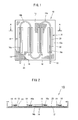
- FIGS. 1 to 5 show a first embodiment of the present invention, and a cooling/heating panel of the embodiment is a ceiling-mounted cooling/heating panel 10, and is provided with a planar radiation panel 12.
- the radiation panel 12 is molded with: a metal plate formed of aluminum or iron; a plaster board; or concrete, and a plurality of acoustic absorption holes 14 are perforated and formed.
- a heat exchange pipe 16 is provided to be held by means of a holding member 18 as described later.
- straight portions 16a crossing a unidirectional width of the radiation panel 12 and curved portions 16b returning while they are curved before reaching an end part of the radiation panel 12 are alternately formed, and consecutively meander.
- the holding members 18 for holding the straight portions 16a of the heat exchange pipe 16 are mounted on the backside 12a of the radiation panel 12, as shown in FIGS. 1 to 3 .
- the holding members 18 are formed of a metal such as an aluminum-extruded material; are elongated members mounted along the straight portions 16a of the heat exchange pipe 16; and are uniform in a cross-sectional shape of a longitudinal direction.
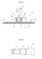
- a cross-sectional shape of the holding member 18, as shown in FIG. 3 is provided with a soaking plate 20 which is superimposed on the backside 12a of the radiation panel 12, and a holding portion 22 for holding the heat exchange pipe 16 is provided at a center of the soaking plate 20.
- a semicircular curved portion 22a which is erected from the soaking plate 20 and opens upward, is formed at a tip end of the curved portion 22a; and an inside diameter d of the curved portion 22a is slightly smaller than an outside diameter D of the heat exchange pipe 16 at normal temperature and is formed; an inner circumferential face of the curved portion 22a comes into intimate contact with an outer circumferential face of the heat exchange pipe 16; and a side face of the heat exchange pipe 16 is repulsively held between both sides.
- an opening 27 between a pair of the curved portions 22a is formed to be slightly smaller than the inside diameter d of the holding member 18, exerted by the curved portion 22a; and the heat exchange pipe 16 is provided to be elastically deformed by receiving it by the wing portion 22b and engagable between the curved portions 22a.
- Primer treatment for the sake of ensuring adhesiveness is applied to the backside 12a of the radiation panel 12 on which the holding member 18 is to be mounted; and the backside 12a is bonded with a hot melt adhesive 25 formed of a thermally plastic resin, for example.
- the backside of the holding member 18 is black-coated so as to be hardly visible via the acoustic absorption hole 14 from a top side of the radiation panel 12.
- the heat exchange pipe 16, as shown in FIG. 4 is a tube with gas barrier properties, structured to be three-layered; a first layer 17 positioned on an inner circumferential face is formed of polyurethane; a second layer 19 outside of the first layer is formed of an ethylene-vinyl alcohol copolymer (hereinafter, referred to as EVOH); and a third layer 21 positioned on an outer circumferential face outside of the second layer is formed of polyurethane.
- the EVOH has high gas barrier properties, and precludes oxygen contained in air from dissolving into a heat exchange fluid passing through the heat exchange pipe 16.
- polyurethane is soft and is easily deformable, even if the EVOH is provided in the second layer 19, the pipe is easily inserted into the holding portion 22 of the holding member 18. Further, polyurethane has rebound resilience, so that an outside diameter returns to its original position after the pipe has been inserted into the holding portion 22; the pipe is reliably held in intimate contact with an interior face of the holding portion 22; and thermal conduction becomes appropriate.
- the heat exchange pipe 16 is pressed between a pair of wing portions 22b; and the curved portion 22a and the heat exchange pipe 16 are elastically deformed, are pushed and elastically latched between the curved portions 22a.
- a jig used exclusively for pushing the heat exchange pipe 16 into the curved portion 22a of the holding member 18 may be employed.
- a noninflammable sheet 23 is laid out at a portion other than the holding member 18.
- the noninflammable sheet 23 is a ceramic sheet or a glass wool sheet, for example, or other noninflammable sheet-like material.
- the noninflammable sheet 23, as shown in FIG. 3 is inserted into a cutout portion 20a formed on a backside of a bilateral rim part of the soaking plate 20 of the holding member 18, and the rim parts are thereby held.
- the ceiling-mounted cooling/heating panels 10 are arranged and mounted on an interior ceiling so that the backside 12a of the radiation panel 12 is at a loft side. Afterwards, ends of the heat exchange pipe 16 are connected to each other by means of a connecting member 24. One end of the heat exchange pipe 16 with the plurality of ceiling-mounted cooling/heating panels 10 being connected thereto is connected to a supply-side main pipe 26, and the other end of the pipe is connected to a return-side main pipe 28.
- the supply-side main pipe 26 and the return-side main pipe 28 are connected to a heat source 30 such as a water heater.
- the heat source 30 supplies a heat exchange fluid of a desired temperature to the heat exchange pipe 16 of the ceiling-mounted cooling/heating panel 10.
- the heat exchange fluid is water, for example.
- the water of a predetermined temperature that was supplied from the heat source 30 to the supply-side main pipe 26 is supplied from one end of the heat exchange pipe 16.
- the supplied water passes through the plurality of heat exchange pipes 16 connected via the connecting member 24, and is then heat-exchanged; and the heat-exchanged water flows from the other end to the return-side main pipe 28, and further, returns to the heat source 30.
- heat exchange is performed with the radiation panel 12 via the holding member 18.
- water is adjusted again at a desired temperature, and is supplied to a supply-side main pipe 26.
- the ceiling-mounted cooling/heating panel 10 of the embodiment has its simple structure and is capable of reliably performing heat exchange.
- the holding member 18 is formed of a metal with high thermal conductivity, so that: heat exchange is performed via the holding member 18 between the heat exchange pipe 16 and the radiation panel 12; and thermal efficiency is appropriate. Further, an outside diameter D of the heat exchange pipe 16 becomes slightly larger than an inside diameter d of the holding member 18 at normal temperature; an outer circumferential face of the heat exchange pipe 16 reliably comes into intimate contact with an interior face of the holding member 18; and thermal conduction is appropriately performed. In particular, in a case where cool water is flown into the heat exchange pipe 16 at the time of cooling, the heat exchange pipe 16 becomes lower in temperature than the holding member 18, and shrinks more significantly than the holding member 18.
- the outside diameter D of the heat exchange pipe 16 is slightly larger than the inside diameter d of the holding member 18, so that: the heat exchange pipe 16 reliably comes into intimate contact with the interior face of the holding member 18; and thermal conduction is appropriately performed.
- the diameter of the heat exchange pipe 16 becomes slightly larger at a temperature and pressure of the water, and the heat exchange pipe 16 comes into intimate contact with the curved portion 22a of the holding member 18 more strongly. In this manner, heat exchange efficiency between the heat exchange pipe 16 and the holding member 18 can be appropriately obtained.
- the heat exchange pipe 16 is structured to be three-layered; the first layer 17 and the third layer 21 are formed of polyurethane, are flexible, and are easily workable; and the second layer 19 is formed of the EVOH with high gas barrier properties, and precludes the oxygen contained in air from dissolving into circulating water. Since oxygen does not dissolve in water, even if a connecting member 24 or the like is formed of a metal, the connecting member does not corrode, allowing its durability to be maintained.
- the heat exchange pipe 16 is mounted and held by means of an elastic force exerted by holding the pipe with the holding portion 22 of the holding member 18, thus eliminating a specific latching device and simplifying its structure.
- the heat exchange pipe 16 is easily mountable or removable.
- the pipe can be mounted by a simple operation of merely pressing it between wing portions 22b of the holding portion 22; is guided to the wing portions 22b of the holding portion 22; and can be simply pushed into the curved portion 22a.
- the pipe is guided into the wing portion 22b, whereby, even if an excessive force is applied to the heating portion 22, the pipe is never broken and is safe.
- a mass of the ceiling-mounted cooling/heating panel 10 can be reduced by the order of 10%; and as to buildings in which the ceiling-mounted cooling/heating panels 10 are employed, the reduction effect of the mass of the cooling/heating panel 10 greatly influences earthquake proof properties or the like.
- the metallic heat exchange pipe is easily plastically deformed, and, for example, in a case where the pipe is attached to the holding member 18, the pipe must be held by a deformation quantity within an elastic limit when the pipe is elastically deformed and is repulsively brought into contact with somewhere, and its dimensional setting becomes difficult. Therefore, when the pipe is attached to the holding member 18, the pipe is easily plastically deformed, and in the case of a metallic heat exchange pipe, unlike the embodiment, the heat exchange pipe cannot be elastically brought into intimate contact with the curved portion 22a all over a full length.
- a portion other than a receptacle 18 of the radiation panel 12 is covered with the noninflammable sheet 23, thus improving noninflammable properties, which precludes the heat exchange pipe 16 from burning in case of fire. Even if an inexpensive synthetic resin is used for the heat exchange pipe 16, it is possible to obtain accreditation of noninflammable properties.
- the heat exchange pipe 16 may be structured to be four-layered, as shown in FIG. 6 , apart from being structured in three-layered.
- a first layer 34 positioned on an inner circumferential face is formed of nylon
- a second layer 36 outside of the first layer is formed of polyurethane.
- a third layer outside of the second layer is formed of the EVOH
- a fourth layer 40 positioned on an outer circumferential face outside of the third layer is formed of polyurethane.
- Nylon of the first layer 34 is strong to water, thus making it possible to enhance durability of the heat exchange pipe 16 or the like.
- nylon can be laminated outside of the gas barrier tube, or alternatively, a publicly known resin other than nylon can also be laminated.
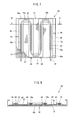
- holding members 44 for holding the straight portions 16a of the heat exchange pipe 16 are mounted on the backside 12a of the radiation panel 12.
- the holding members 44 are formed of a metal such as an aluminum-extruded material; are elongated members mounted along the straight portions 16a of the heat exchange pipe 16; and are uniform in the cross-sectional shape of a longitudinal direction.
- Soaking plates 46 which are plate bodies superimposed on the backside 12a of the radiation panel 12, are provided at the holding members 44, and holding portions 22 are provided at the cores of the soaking plates 46.
- the holding members 44 are mounted from end to end of the radiation panel 12, reinforcing the radiation panel 12 and precluding slackness.
- the holding portions 22 are provided only at portions at which the straight portions 16a of the heat exchange pipe 16, of the soaking plate 46, are positioned, and hold the straight portions 16a. Ends 46a in the longitudinal direction of the soaking plates 46 come into contact with curved portions 16b that are continuous relative to the straight portions 16a of the heat exchange pipe 16. Further, between the ends 46a in the longitudinal direction of the soaking plates 46 on which the curved portions 16b are positioned, soaking plates 47 are attached to the backside of the radiation panel 12. Moreover, the holding portions 22 are removed from the vicinity of the ends 46a of the soaking plates 46 coming into contact with the curved portions 16b. Therefore, the curved portions 16b are merely placed on the soaking plates 46, 47.
- the holding portions 22 may be removed only at the side at which the curved portions 16b of the heat exchange pipe 16 is curved, and in this case also, advantageous effect similar to the aforementioned one is attained.
- the curved portions 16b may connect to the holding portions 22 of the adjacent soaking plates 46 so as to climb over without removing the holding portions 22. In this case, the number of man-hours of the holding portions 22 can be reduced.
- the ceiling-mounted cooling/heating panel 42 of the embodiment has a similar advantageous effect by the use method similar to the abovementioned embodiment.
- the soaking plates 46, 47 are positioned between the curved portion 16b of the heat exchange pipe 16 and the radiation panel 12, thus improving thermal efficiency more remarkably.
- the panel is reinforced by the holding members 44, precluding slackness and improving appearance as well.
- FIGS. 9 to 12 a third embodiment of the present invention will be described referring to FIGS. 9 to 12 .
- like constituent elements of the above-described embodiments are designated by like reference numerals and a duplicate description is omitted.
- the holding members 18 for holding the straight portions 16a of the heat exchange pipe 16 are mounted on the backside 12a of the radiation panel 12.
- the heat exchange pipe 16 of the embodiment is mounted on the holding portion 22 while the pipe is curved at every interval in the same direction relative to the holding member 18 fixed to the radiation panel 12.
- the ceiling-mounted cooling/heating panel 50 of the embodiment also has a similar advantageous effect by the use method similar to that of the above-described embodiments, and a curving direction of the heat exchange pipe 16 is uniform, so that the heat exchange pipe 16 is curved in the direction of the winding habit of the heat exchange pipe 16, allowing setting of the curved portions 16b to be provided more easily.
- both ends of the heat exchange pipe 16 may be brought to both sides of the radiation panel 12. In this case also, advantageous effect similar to that of the above-described embodiments can be attained.
- the cooling/heating panel of the present invention is not limitative to each of the above-described embodiments, the layout or shape of a heat exchange pipe can be appropriately set, and the layout and meandering or curving counts of the heat exchange pipe can also be appropriately changed.
- the shape or size of the radiation panel and gaps of acoustic absorption holes or the like can also be appropriately selected.
- a material for, or thickness of, a radiation panel or a noninflammable sheet can also be appropriately selected, and the heating/cooling panel is applicable to an appropriate location such as a wall other than a ceiling.
- a process such as aluminum vapor deposition may be performed for an outer circumferential face in order to enhance gas barrier properties.
Landscapes
- Engineering & Computer Science (AREA)
- Chemical & Material Sciences (AREA)
- Combustion & Propulsion (AREA)
- Mechanical Engineering (AREA)
- General Engineering & Computer Science (AREA)
- Physics & Mathematics (AREA)
- Thermal Sciences (AREA)
- Life Sciences & Earth Sciences (AREA)
- Sustainable Development (AREA)
- Steam Or Hot-Water Central Heating Systems (AREA)
Abstract
A cooling/heating panel has a planar radiation panel (12), a metallic holding member (18) arranged partially on a backside of the radiation panel (12), and a resin heat exchange pipe (16) held by the holding member (18). The holding member (18) has: a flat soaking plate (20) which is superimposed on the radiation panel (12); and a holding portion (22) which is erected on the soaking plate (20) and latches the heat exchange pipe (16). The heat exchange pipe (16) has an outside diameter larger than an inside diameter of the holding portion (22) before the heat exchange pipe (16) is attached to the holding portion (22) and in a state in which the heat exchange pipe (16) is attached to the holding portion (22), the holding portion (22) holds a side face of the heat exchange pipe (16) repulsively from both sides.
Description
- The present invention relates to a cooling/heating panel which performs interior cooling or heating by means of radiation heat obtained by heat exchange via a fluid.
- Conventionally, a radiation-type cooling/heating panel constructed on ceiling has been known. Such a cooling/heating panel has a radiation panel made of a metal or a plaster board; a metallic or resin heat exchange pipe is disposed at a backside of the radiation panel; and this cooling/heating panel is installed on a ceiling. A fluid of a predetermined temperature is flowed in the heat exchange pipe installed on the ceiling, and interior cooling/heating is performed.
- As a ceiling cooling/heating panel having a metallic pipe, like a ceiling element disclosed in Patent Document 1, there is the one in which a metallic heat exchange pipe such as copper is mounted on a backside of a ceiling cooling/heating panel. The metallic heat exchange pipe per se has appropriate thermal conductivity; and has high gas barrier properties, so that oxygen does not permeate, or alternatively, circuit components or the like of a connecting portion do not corrode.
- On the other hand, the resin heat exchange pipe has a feature that it is well workable, is lightweight, and is low in cost, whereas its thermal conductivity is low in comparison with that of the metallic heat exchange pipe. Therefore, like a ceiling radiation cooling/heating panel disclosed in Patent Document 2, there is proposed the one having a structure in which: a heat exchange pipe is covered with a metallic soaking plate and the heat exchange pipe is held between the soaking plate and a backside of a radiation panel. In this manner, a heat from the heat exchange pipe is efficiently transmitted to the radiation panel.
- However, the resin heat exchange pipe has entailed a problem that: gas barrier properties are poor; oxygen contained in air enters a heat exchange medium passing through the heat exchange pipe; and circuit components of a heat exchange medium corrode. Further, a plurality of acoustic absorption holes are perforated and formed on the ceiling cooling/heating panel, and in case of fire, there is apprehension that: flames enter the backside of the radiation panel from the acoustic absorption holes; and the heat exchange pipe bums. Otherwise, there is a danger that: the pipe is melted by a heat; and the melted pipe leaks from the acoustic absorption holes of the radiation panel.
- Therefore, like the ceiling radiation cooling/heating panel disclosed in Patent Document 3, there is proposed the one allowing a noninflammable sheet or a noninflammable plate material to be interposed between a radiation panel and a heat exchange panel, a respective one of which has acoustic absorption holes formed thereon.
- Patent Document 1: Japanese Laid-open Patent Application No.
10-232035 - Patent Document 2: Japanese Laid-open Patent Application No
2006-170551 - Patent Document 3: Japanese Laid-open Patent Application No.
10-227495 - However, the above-described metallic heat exchange pipe as disclosed in Patent Document 1 of the prior art is large in mass; a load upon a ceiling material increases; a support member of the ceiling material increases and becomes heavy; and as a whole, the mass of a ceiling portion increases. As a result, a structure such as earthquake proof of buildings has been thereby affected. Moreover, a metallic heat exchange pipe is hardly processed in a meandering shape, and is easily plastically deformed. For example, if a metallic heat exchange pipe is attached to a pipe holding portion of a ceiling material, the pipe must be attached in a deformation quantity within an elastic limit in order for the pipe to be elastically deformed and repulsively intimately contacted, thus making it difficult to provide dimensional setting such that the pipe is hardly detached and can be elastically held. Therefore, elastic holding is realistically difficult, and the pipe cannot be mounted while a full surface is in intimate contact with the holding portion all over the full length of the heat exchange pipe. Further, between the heat exchange pipe at which the full surface is not in intimate contact therewith and its holding portion, thermal conduction is not good due to the presence of a spatial layer, resulting in a failure to exploit the virtue of thermal conduction of a metal.
- In addition, like the abovementioned Patent Document 2, in the case of a structure in which a heat exchange pipe is held between metal plates, with the heat exchange pipe being precisely positioned on a radiation panel, a metallic soaking plate must be fixed so as to cover the radiation panel at a predetermined position, making assembling or construction difficult and increasing the number of man-hours. Therefore, a cooling/heating panel and cooling/heating equipment employing the panel has been prone to become high in cost.
- Further, like the abovementioned Patent Document 3, in a case where a noninflammable sheet is provided between the heat exchange pipe and the radiation panel, since the noninflammable sheet uses a ceramic sheet or the like, its heat conductivity has been significantly lowered in comparison with that of a metal. Therefore, unlike a metal, a heat cannot be reliably efficiently transmitted, and thermal efficiency of the cooling/heating equipment has become lowered.
- The present invention has been made in view of the above-described problem of the prior art, and aims to provide a cooling/heating panel which has high heat exchange efficiency, has a simple structure, is lightweight, and moreover, is easily assembled as well.
- The present invention is directed to a cooling/heating panel, comprising:
- a planar radiation panel;
- a metallic holding member arranged partially on a backside of the radiation panel; and
- a resin heat exchange pipe held on the holding member, wherein:
- the holding member has a flat soaking plate and a holding portion formed thereon, the soaking plate being superimposed on the radiation panel, the holding portion being erected on the soaking plate and latching the heat exchange pipe;
- an outside diameter of the heat exchange pipe is larger than an inside diameter of the holding portion before the pipe is attached to the holding portion; and
- the holding portion repulsively holds a side face of the heat exchange pipe from both sides in a state in which the heat exchange pipe is attached to the holding portion.
- The radiation panel has a plurality of acoustic absorption holes which are perforated in a thickness direction; and a noninflammable sheet is laid out at a portion other than a site at which the soaking plate is provided.
- The holding member is an elongated member mounted along a straight portion of the heat exchange pipe; and a cross-sectional shape of the holding member has a soaking plate and a semicircular curved portion integrally formed thereon, the soaking plate serving as a plate body superimposed on the radiation panel, the semicircular curved portion being erected from the soaking plate and opening upward.
- The soaking plate is provided to ensure that: the holding portion is removed from the vicinity of an end of the soaking plate, being continuous to a straight portion of the heat exchange pipe that is curved and mounted on the holding member, reaching a curved portion, and facing the curved portion; and the curved heat exchange pipe can abut against the soaking plate.
- An opening between the pair of curved portions is formed to be smaller than an inside diameter of the holding portion, formed by the curved portion, and is provided to elastically deform the heat exchange pipe and to be engagable into the holding portion.
- The heat exchange pipe is a gas barrier tube; a layer positioned on an inner circumferential face is formed of polyurethane; a layer outside thereof is formed of an ethylene-vinyl alcohol copolymer; and a layer positioned at an outer circumferential face outside thereof is formed of polyurethane.
- The heat exchange pipe is a gas barrier tube; a layer positioned on an inner circumferential face is formed of nylon; a layer outside thereof is formed polyurethane; a layer outside thereof is formed of an ethylene-vinyl alcohol copolymer; a layer positioned on an outer circumferential face outside thereof is formed of polyurethane.
- A cooling/heating panel of the present invention is adapted to easily mount a heat exchange pipe with a simple structure; thermal conduction between a metallic holding member and a resin heat exchange pipe is appropriate; and the metallic holding member is capable of reliably transmitting a temperature of a heat exchange fluid of the heat exchange pipe to a radiation panel. In this manner, the cooling/heating panel can be formed having high thermal exchange efficiency between the fluid flowing in the heat exchange pipe and the radiation panel and high energy efficiency.
- In addition, in the case of comparison with a conventional metallic heat exchange pipe, a mass of the cooling/heating panel can be reduced, and considering the entire buildings, a reduction effect of the mass of the cooling/heating panel is significantly great. Further, the metallic heat exchange pipe is easily plastically deformable, and it is difficult to attach the pipe to the holding member so as to be repulsively in intimate contact therewith; and however, with a structure of the present invention, appropriate thermal conduction is obtained even in the resin heat exchange pipe.
- In addition, a noninflammable sheet is provided at a portion other than a receptacle-mounted portion on the backside of the radiation panel, and even if a resin is used for the heat exchange pipe, noninflammable properties can be reliably obtained.
- Further, the cooling/heating panel of the present invention is lightweight and has high thermal exchange efficiency, and is capable of restraining oxidization of connecting components.
-
- [
FIG. 1 ] It is a front view of a cooling/heating panel of a first embodiment of the present invention. - [
FIG. 2 ] It is a sectional view taken along the line A-A ofFIG. 1 . - [
FIG. 3 ] It is an enlarged sectional view taken along the line A-A. - [
FIG. 4 ] It is a partially fragmental perspective view of a heat exchange pipe of the cooling/heating panel of the embodiment. - [
FIG. 5 ] It is a schematic view showing a method of using the cooling/heating panel of the embodiment. - [
FIG. 6 ] It is a partially fragmental perspective view showing a modified example of the heat exchange pipe of the cooling/heating panel of the embodiment. - [
FIG. 7 ] It is a front view of a cooling/heating panel of a second embodiment of the present invention. - [
FIG. 8 ] It is a sectional view taken along the line B-B ofFIG. 7 . - [
FIG. 9 ] It is a front view of a cooling/heating panel of a third embodiment of the present invention. - [
FIG. 10 ] It is an enlarged sectional view taken along the line C-C ofFIG. 9 . - [
FIG. 11 ] It is a schematic view showing a method of using the cooling/heating panel of the third embodiment. - [
FIG. 12 ] It is a front view showing a modified example of layout of a heat exchange pipe of the third embodiment. -
- 10
- Ceiling-mounted cooling/heating panel
- 12
- Radiation panel
- 14
- Acoustic absorption hole
- 16
- Heat exchange pipe
- 16a
- Straight portion
- 16b
- Curved portion
- 18
- Holding member
- 20
- Soaking plate
- 22
- Holding portion
- 22a
- Curved portion
- 22b
- Wing portion
- 23
- Noninflammable sheet
- Hereinafter, embodiments of the present invention will be described referring to the drawings.
FIGS. 1 to 5 show a first embodiment of the present invention, and a cooling/heating panel of the embodiment is a ceiling-mounted cooling/heating panel 10, and is provided with aplanar radiation panel 12. Theradiation panel 12 is molded with: a metal plate formed of aluminum or iron; a plaster board; or concrete, and a plurality of acoustic absorption holes 14 are perforated and formed. On abackside 12a of theradiation panel 12, aheat exchange pipe 16 is provided to be held by means of a holdingmember 18 as described later. In theheat exchange pipe 16,straight portions 16a crossing a unidirectional width of theradiation panel 12 andcurved portions 16b returning while they are curved before reaching an end part of theradiation panel 12 are alternately formed, and consecutively meander. - On the
backside 12a of theradiation panel 12, as shown inFIGS. 1 to 3 , the holdingmembers 18 for holding thestraight portions 16a of theheat exchange pipe 16 are mounted. The holdingmembers 18 are formed of a metal such as an aluminum-extruded material; are elongated members mounted along thestraight portions 16a of theheat exchange pipe 16; and are uniform in a cross-sectional shape of a longitudinal direction. A cross-sectional shape of the holdingmember 18, as shown inFIG. 3 , is provided with a soakingplate 20 which is superimposed on thebackside 12a of theradiation panel 12, and a holdingportion 22 for holding theheat exchange pipe 16 is provided at a center of the soakingplate 20. A semicircularcurved portion 22a, which is erected from the soakingplate 20 and opens upward, is formed at a tip end of thecurved portion 22a; and an inside diameter d of thecurved portion 22a is slightly smaller than an outside diameter D of theheat exchange pipe 16 at normal temperature and is formed; an inner circumferential face of thecurved portion 22a comes into intimate contact with an outer circumferential face of theheat exchange pipe 16; and a side face of theheat exchange pipe 16 is repulsively held between both sides. In addition, anopening 27 between a pair of thecurved portions 22a is formed to be slightly smaller than the inside diameter d of the holdingmember 18, exerted by thecurved portion 22a; and theheat exchange pipe 16 is provided to be elastically deformed by receiving it by thewing portion 22b and engagable between thecurved portions 22a. - Primer treatment for the sake of ensuring adhesiveness is applied to the
backside 12a of theradiation panel 12 on which the holdingmember 18 is to be mounted; and thebackside 12a is bonded with a hot melt adhesive 25 formed of a thermally plastic resin, for example. The backside of the holdingmember 18 is black-coated so as to be hardly visible via theacoustic absorption hole 14 from a top side of theradiation panel 12. - The
heat exchange pipe 16, as shown inFIG. 4 , is a tube with gas barrier properties, structured to be three-layered; afirst layer 17 positioned on an inner circumferential face is formed of polyurethane; asecond layer 19 outside of the first layer is formed of an ethylene-vinyl alcohol copolymer (hereinafter, referred to as EVOH); and athird layer 21 positioned on an outer circumferential face outside of the second layer is formed of polyurethane. The EVOH has high gas barrier properties, and precludes oxygen contained in air from dissolving into a heat exchange fluid passing through theheat exchange pipe 16. Since polyurethane is soft and is easily deformable, even if the EVOH is provided in thesecond layer 19, the pipe is easily inserted into the holdingportion 22 of the holdingmember 18. Further, polyurethane has rebound resilience, so that an outside diameter returns to its original position after the pipe has been inserted into the holdingportion 22; the pipe is reliably held in intimate contact with an interior face of the holdingportion 22; and thermal conduction becomes appropriate. - Next, a method of mounting the
heat exchange pipe 16 on the holdingmember 18 will be described. Theheat exchange pipe 16 is pressed between a pair ofwing portions 22b; and thecurved portion 22a and theheat exchange pipe 16 are elastically deformed, are pushed and elastically latched between thecurved portions 22a. At this time, a jig used exclusively for pushing theheat exchange pipe 16 into thecurved portion 22a of the holdingmember 18 may be employed. - On the
backside 12a of theradiation panel 12, anoninflammable sheet 23 is laid out at a portion other than the holdingmember 18. Thenoninflammable sheet 23 is a ceramic sheet or a glass wool sheet, for example, or other noninflammable sheet-like material. Thenoninflammable sheet 23, as shown inFIG. 3 , is inserted into acutout portion 20a formed on a backside of a bilateral rim part of the soakingplate 20 of the holdingmember 18, and the rim parts are thereby held. - Next, a method of using the ceiling-mounted cooling/
heating panel 10 will be described referring toFIG. 5 . The ceiling-mounted cooling/heating panels 10 are arranged and mounted on an interior ceiling so that thebackside 12a of theradiation panel 12 is at a loft side. Afterwards, ends of theheat exchange pipe 16 are connected to each other by means of a connectingmember 24. One end of theheat exchange pipe 16 with the plurality of ceiling-mounted cooling/heating panels 10 being connected thereto is connected to a supply-sidemain pipe 26, and the other end of the pipe is connected to a return-sidemain pipe 28. The supply-sidemain pipe 26 and the return-sidemain pipe 28 are connected to aheat source 30 such as a water heater. - The
heat source 30 supplies a heat exchange fluid of a desired temperature to theheat exchange pipe 16 of the ceiling-mounted cooling/heating panel 10. The heat exchange fluid is water, for example. The water of a predetermined temperature that was supplied from theheat source 30 to the supply-sidemain pipe 26 is supplied from one end of theheat exchange pipe 16. The supplied water passes through the plurality ofheat exchange pipes 16 connected via the connectingmember 24, and is then heat-exchanged; and the heat-exchanged water flows from the other end to the return-sidemain pipe 28, and further, returns to theheat source 30. In a course in which water passes through theheat exchange pipe 16, heat exchange is performed with theradiation panel 12 via the holdingmember 18. At theheat source 30, water is adjusted again at a desired temperature, and is supplied to a supply-sidemain pipe 26. - The ceiling-mounted cooling/
heating panel 10 of the embodiment has its simple structure and is capable of reliably performing heat exchange. The holdingmember 18 is formed of a metal with high thermal conductivity, so that: heat exchange is performed via the holdingmember 18 between theheat exchange pipe 16 and theradiation panel 12; and thermal efficiency is appropriate. Further, an outside diameter D of theheat exchange pipe 16 becomes slightly larger than an inside diameter d of the holdingmember 18 at normal temperature; an outer circumferential face of theheat exchange pipe 16 reliably comes into intimate contact with an interior face of the holdingmember 18; and thermal conduction is appropriately performed. In particular, in a case where cool water is flown into theheat exchange pipe 16 at the time of cooling, theheat exchange pipe 16 becomes lower in temperature than the holdingmember 18, and shrinks more significantly than the holdingmember 18. However, at normal temperature, the outside diameter D of theheat exchange pipe 16 is slightly larger than the inside diameter d of the holdingmember 18, so that: theheat exchange pipe 16 reliably comes into intimate contact with the interior face of the holdingmember 18; and thermal conduction is appropriately performed. In addition, if hot water is passed through theheat exchange pipe 16, the diameter of theheat exchange pipe 16 becomes slightly larger at a temperature and pressure of the water, and theheat exchange pipe 16 comes into intimate contact with thecurved portion 22a of the holdingmember 18 more strongly. In this manner, heat exchange efficiency between theheat exchange pipe 16 and the holdingmember 18 can be appropriately obtained. - Further, the
heat exchange pipe 16 is structured to be three-layered; thefirst layer 17 and thethird layer 21 are formed of polyurethane, are flexible, and are easily workable; and thesecond layer 19 is formed of the EVOH with high gas barrier properties, and precludes the oxygen contained in air from dissolving into circulating water. Since oxygen does not dissolve in water, even if a connectingmember 24 or the like is formed of a metal, the connecting member does not corrode, allowing its durability to be maintained. - The
heat exchange pipe 16 is mounted and held by means of an elastic force exerted by holding the pipe with the holdingportion 22 of the holdingmember 18, thus eliminating a specific latching device and simplifying its structure. In addition, theheat exchange pipe 16 is easily mountable or removable. The pipe can be mounted by a simple operation of merely pressing it betweenwing portions 22b of the holdingportion 22; is guided to thewing portions 22b of the holdingportion 22; and can be simply pushed into thecurved portion 22a. The pipe is guided into thewing portion 22b, whereby, even if an excessive force is applied to theheating portion 22, the pipe is never broken and is safe. - In addition, in the case of comparison with the conventional heat exchange pipe formed of a metal such as copper, a mass of the ceiling-mounted cooling/
heating panel 10 can be reduced by the order of 10%; and as to buildings in which the ceiling-mounted cooling/heating panels 10 are employed, the reduction effect of the mass of the cooling/heating panel 10 greatly influences earthquake proof properties or the like. - Further, the metallic heat exchange pipe is easily plastically deformed, and, for example, in a case where the pipe is attached to the holding
member 18, the pipe must be held by a deformation quantity within an elastic limit when the pipe is elastically deformed and is repulsively brought into contact with somewhere, and its dimensional setting becomes difficult. Therefore, when the pipe is attached to the holdingmember 18, the pipe is easily plastically deformed, and in the case of a metallic heat exchange pipe, unlike the embodiment, the heat exchange pipe cannot be elastically brought into intimate contact with thecurved portion 22a all over a full length. - Moreover, on the ceiling-mounted cooling/
heating panel 10, a portion other than areceptacle 18 of theradiation panel 12 is covered with thenoninflammable sheet 23, thus improving noninflammable properties, which precludes theheat exchange pipe 16 from burning in case of fire. Even if an inexpensive synthetic resin is used for theheat exchange pipe 16, it is possible to obtain accreditation of noninflammable properties. - The
heat exchange pipe 16 may be structured to be four-layered, as shown inFIG. 6 , apart from being structured in three-layered. In a gas barrier tube of the heat exchange pipe 32 shown inFIG. 6 , afirst layer 34 positioned on an inner circumferential face is formed of nylon, and asecond layer 36 outside of the first layer is formed of polyurethane. In addition, a third layer outside of the second layer is formed of the EVOH, and afourth layer 40 positioned on an outer circumferential face outside of the third layer is formed of polyurethane. Nylon of thefirst layer 34 is strong to water, thus making it possible to enhance durability of theheat exchange pipe 16 or the like. Further, nylon can be laminated outside of the gas barrier tube, or alternatively, a publicly known resin other than nylon can also be laminated. - Next, a second embodiment of the present invention will be described referring to
FIGS. 7 and 8 . Hereinafter, like constituent elements in the above-described embodiment are designated by like reference numerals and a duplicate description is omitted. In a ceiling-mounted cooling/heating panel 42 of the embodiment as well, holdingmembers 44 for holding thestraight portions 16a of theheat exchange pipe 16 are mounted on thebackside 12a of theradiation panel 12. The holdingmembers 44 are formed of a metal such as an aluminum-extruded material; are elongated members mounted along thestraight portions 16a of theheat exchange pipe 16; and are uniform in the cross-sectional shape of a longitudinal direction. Soakingplates 46, which are plate bodies superimposed on thebackside 12a of theradiation panel 12, are provided at the holdingmembers 44, and holdingportions 22 are provided at the cores of the soakingplates 46. The holdingmembers 44 are mounted from end to end of theradiation panel 12, reinforcing theradiation panel 12 and precluding slackness. - The holding
portions 22 are provided only at portions at which thestraight portions 16a of theheat exchange pipe 16, of the soakingplate 46, are positioned, and hold thestraight portions 16a.Ends 46a in the longitudinal direction of the soakingplates 46 come into contact withcurved portions 16b that are continuous relative to thestraight portions 16a of theheat exchange pipe 16. Further, between theends 46a in the longitudinal direction of the soakingplates 46 on which thecurved portions 16b are positioned, soakingplates 47 are attached to the backside of theradiation panel 12. Moreover, the holdingportions 22 are removed from the vicinity of theends 46a of the soakingplates 46 coming into contact with thecurved portions 16b. Therefore, thecurved portions 16b are merely placed on the soakingplates - The holding
portions 22 may be removed only at the side at which thecurved portions 16b of theheat exchange pipe 16 is curved, and in this case also, advantageous effect similar to the aforementioned one is attained. Thecurved portions 16b may connect to the holdingportions 22 of theadjacent soaking plates 46 so as to climb over without removing the holdingportions 22. In this case, the number of man-hours of the holdingportions 22 can be reduced. - The ceiling-mounted cooling/
heating panel 42 of the embodiment has a similar advantageous effect by the use method similar to the abovementioned embodiment. The soakingplates curved portion 16b of theheat exchange pipe 16 and theradiation panel 12, thus improving thermal efficiency more remarkably. In addition, even if theradiation panel 12 is large, the panel is reinforced by the holdingmembers 44, precluding slackness and improving appearance as well. - Next, a third embodiment of the present invention will be described referring to
FIGS. 9 to 12 . Hereinafter, like constituent elements of the above-described embodiments are designated by like reference numerals and a duplicate description is omitted. In a ceiling-mounted cooling/heating panel 50 of the embodiment as well, the holdingmembers 18 for holding thestraight portions 16a of theheat exchange pipe 16 are mounted on thebackside 12a of theradiation panel 12. - The
heat exchange pipe 16 of the embodiment is mounted on the holdingportion 22 while the pipe is curved at every interval in the same direction relative to the holdingmember 18 fixed to theradiation panel 12. - The ceiling-mounted cooling/
heating panel 50 of the embodiment also has a similar advantageous effect by the use method similar to that of the above-described embodiments, and a curving direction of theheat exchange pipe 16 is uniform, so that theheat exchange pipe 16 is curved in the direction of the winding habit of theheat exchange pipe 16, allowing setting of thecurved portions 16b to be provided more easily. - Similarly, as shown in
FIG. 12 , both ends of theheat exchange pipe 16 may be brought to both sides of theradiation panel 12. In this case also, advantageous effect similar to that of the above-described embodiments can be attained. - The cooling/heating panel of the present invention is not limitative to each of the above-described embodiments, the layout or shape of a heat exchange pipe can be appropriately set, and the layout and meandering or curving counts of the heat exchange pipe can also be appropriately changed. The shape or size of the radiation panel and gaps of acoustic absorption holes or the like can also be appropriately selected. A material for, or thickness of, a radiation panel or a noninflammable sheet can also be appropriately selected, and the heating/cooling panel is applicable to an appropriate location such as a wall other than a ceiling. In addition, in the heat exchange pipe, a process such as aluminum vapor deposition may be performed for an outer circumferential face in order to enhance gas barrier properties.
Claims (7)
- A cooling/heating panel, comprising:a planar radiation panel;a metallic holding member arranged partially on a backside of the radiation panel; anda resin heat exchange pipe held on the holding member, wherein:the holding member has a flat soaking plate and a holding portion formed thereon, the soaking plate being superimposed on the radiation panel, the holding portion being erected on the soaking plate and latching the heat exchange pipe;an outside diameter of the heat exchange pipe is larger than an inside diameter of the holding portion before the pipe is attached to the holding portion; andthe holding portion repulsively holds a side face of the heat exchange pipe from both sides in a state in which the heat exchange pipe is attached to the holding portion.
- The cooling/heating panel according to claim 1, wherein:the radiation panel has a plurality of acoustic absorption holes which are perforated in a thickness direction; and a noninflammable sheet is laid out at a portion other than a site at which the soaking plate is provided.
- The cooling/heating panel according to claim 1, wherein:the holding member is an elongated member mounted along a straight portion of the heat exchange pipe; and a cross-sectional shape of the holding member has a soaking plate and a semicircular curved portion integrally formed thereon, the soaking plate serving as a plate body superimposed on the radiation panel, the semicircular curved portion being erected from the soaking plate and opening upward.
- The cooling/heating panel according to claim 3, wherein:the soaking plate is provided to ensure that: the holding portion is removed from the vicinity of an end of the soaking plate, being continuous to a straight portion of the heat exchange pipe that is curved and mounted on the holding member, reaching a curved portion, and facing the curved portion; and the curved heat exchange pipe can abut against the soaking plate.
- The cooling/heating panel according to claim 3, wherein:an opening between the pair of curved portions is formed to be smaller than a inside diameter of the holding portion, formed by the curved portion, and is provided to elastically deform the heat exchange pipe and to be engagable into the holding portion.
- The cooling/heating panel according to claim 1, wherein:the heat exchange pipe is a gas barrier tube; a layer positioned on an inner circumferential face is formed of polyurethane; a layer outside thereof is formed of an ethylene-vinyl alcohol copolymer; and a layer positioned at an outer circumferential face outside thereof is formed of polyurethane.
- The cooling/heating panel according to claim 1, wherein:the heat exchange pipe is a gas barrier tube; a layer positioned on an inner circumferential face is formed of nylon; a layer outside thereof is formed polyurethane; a layer outside thereof is formed of an ethylene-vinyl alcohol copolymer; a layer positioned on an outer circumferential face outside thereof is formed of polyurethane.
Applications Claiming Priority (3)
| Application Number | Priority Date | Filing Date | Title |
|---|---|---|---|
| JP2007107119A JP5046155B2 (en) | 2007-04-16 | 2007-04-16 | Air conditioning panel |
| JP2008016333A JP5224171B2 (en) | 2008-01-28 | 2008-01-28 | Ceiling air conditioning panel |
| PCT/JP2008/057268 WO2008133079A1 (en) | 2007-04-16 | 2008-04-14 | Cooling/heating panel |
Publications (1)
| Publication Number | Publication Date |
|---|---|
| EP2138778A1 true EP2138778A1 (en) | 2009-12-30 |
Family
ID=39925537
Family Applications (1)
| Application Number | Title | Priority Date | Filing Date |
|---|---|---|---|
| EP08740356A Withdrawn EP2138778A1 (en) | 2007-04-16 | 2008-04-14 | Cooling/heating panel |
Country Status (4)
| Country | Link |
|---|---|
| US (1) | US8561677B2 (en) |
| EP (1) | EP2138778A1 (en) |
| CN (1) | CN101680670B (en) |
| WO (1) | WO2008133079A1 (en) |
Cited By (4)
| Publication number | Priority date | Publication date | Assignee | Title |
|---|---|---|---|---|
| ITMO20110245A1 (en) * | 2011-09-27 | 2013-03-28 | Giuseppe Librizzi | RADIANT THERMAL CONDITIONING SYSTEM |
| EP2410246A3 (en) * | 2010-07-20 | 2018-03-14 | KE KELIT Kunststoffwerk Gesellschaft m.b.H. | Method for air conditioning a room |
| EP3404337A4 (en) * | 2016-01-12 | 2019-01-02 | Jiguang Yan | Radiant air conditioning system for heat-producing device |
| EP3839358A1 (en) | 2019-12-18 | 2021-06-23 | Barcol-Air Group AG | Ceiling element for a heating and cooling ceiling |
Families Citing this family (18)
| Publication number | Priority date | Publication date | Assignee | Title |
|---|---|---|---|---|
| BE1018520A5 (en) * | 2009-04-20 | 2011-02-01 | Rofix Nv | CLIMATE CEILING ELEMENT. |
| US10041250B2 (en) * | 2011-06-30 | 2018-08-07 | Enrique Tarraga Sanchez | Modular panel for thermal energy transfer |
| WO2015028946A1 (en) * | 2013-08-28 | 2015-03-05 | Rapole Madhusudhan Rao | Bonded panel with fluid circulating channels for radiant heating/cooling |
| JP6362176B2 (en) * | 2014-09-12 | 2018-07-25 | 株式会社ニチボウ | Automatic fire extinguishing device and fire detection tube used in this automatic fire extinguishing device |
| US20160138875A1 (en) * | 2014-11-14 | 2016-05-19 | Hamilton Sundstrand Corporation | Radiators |
| US10358778B2 (en) | 2015-02-06 | 2019-07-23 | Michael Gregory Theodore, Jr. | Temperature controlled structure assembly |
| US20180298611A1 (en) * | 2017-04-17 | 2018-10-18 | David R. Hall | Configurable Hydronic Structural Panel |
| JP6970421B2 (en) * | 2017-05-22 | 2021-11-24 | 株式会社ササクラ | Radiant panel for air conditioning and its manufacturing method |
| DK3645946T3 (en) * | 2017-06-28 | 2021-07-12 | Price Industries Ltd | Thermally activated building panel |
| CN108661276B (en) * | 2018-01-04 | 2019-12-31 | 深圳东盟建材实业有限公司 | A cooling and heating decorative panel |
| KR102046630B1 (en) * | 2018-02-13 | 2019-11-19 | (주)제이앤씨트레이딩 | Self-assembly hot water mat |
| CN108385873A (en) * | 2018-03-16 | 2018-08-10 | 北方工业大学 | Partition wall with embedded radiant heating pipe and heating system |
| US20220042305A1 (en) * | 2018-09-16 | 2022-02-10 | Armin Buehler | Profiled section for temperature-control of a room, and building element assembly comprising said profiled section |
| US20200149748A1 (en) * | 2018-11-14 | 2020-05-14 | Francesco Giovanni Longo | Building System |
| US11441315B2 (en) * | 2019-05-28 | 2022-09-13 | Hall Labs Llc | System for heating and cooling a room with insulating layer |
| CN112424534B (en) * | 2019-06-20 | 2022-04-29 | Futaeda株式会社 | Radiant panel |
| DE202021100591U1 (en) * | 2021-02-05 | 2022-05-06 | Schmöle GmbH | Intermediate product for the manufacture of a surface heat exchanger and the same |
| US20240018780A1 (en) * | 2022-07-12 | 2024-01-18 | Dreamer Limited | Radiant cooling and/or heating assembly |
Family Cites Families (25)
| Publication number | Priority date | Publication date | Assignee | Title |
|---|---|---|---|---|
| US1800150A (en) * | 1927-01-29 | 1931-04-07 | Musgrave Joseph Leslie | Heating and cooling of buildings |
| JPS5276651U (en) | 1976-09-24 | 1977-06-08 | ||
| JPS55122087U (en) | 1979-02-23 | 1980-08-29 | ||
| JPS5793711U (en) | 1980-11-29 | 1982-06-09 | ||
| JPS62162827A (en) | 1986-01-14 | 1987-07-18 | Matsushita Electric Works Ltd | Floor heating panel |
| JPH0517407U (en) * | 1991-08-12 | 1993-03-05 | 日立電線株式会社 | Panel device for heating |
| JPH06193914A (en) * | 1992-11-06 | 1994-07-15 | Taikisha Ltd | Construction of ceiling radiation type temperature regulator |
| US5454428A (en) * | 1993-11-22 | 1995-10-03 | Radiant Engineering, Inc. | Hydronic radiant heat distribution panel and system |
| US6910526B1 (en) * | 1995-10-06 | 2005-06-28 | Barcol-Air Ag | Contact element and ceiling element for a heating and cooling ceiling |
| JPH1038293A (en) | 1996-07-19 | 1998-02-13 | Shinko Kenzai:Kk | Floor heating pipe fixing member and floor heating structure using floor joist |
| JP2991158B2 (en) | 1996-12-10 | 1999-12-20 | 株式会社トヨックス | Ceiling radiant cooling and heating panel |
| CH691328A5 (en) | 1996-12-20 | 2001-06-29 | Barcol Air | Ceiling element for a heating and cooling ceiling. |
| JPH11118167A (en) | 1997-10-09 | 1999-04-30 | Tohoku Setsubi:Kk | Jig for floor heating, and heating tatami |
| JPH11166742A (en) | 1997-12-02 | 1999-06-22 | Osaka Gas Co Ltd | Heat pipe floor heating panel |
| JP3995226B2 (en) | 1998-10-16 | 2007-10-24 | 株式会社トヨックス | Radiant air conditioning panel |
| JP2002130704A (en) | 2000-10-23 | 2002-05-09 | Sanyo Electric Co Ltd | Radiator for heating |
| US7811646B2 (en) * | 2001-05-14 | 2010-10-12 | Kuraray Co., Ltd. | Modified ethylene-vinyl alcohol copolymer and method for the production thereof |
| JP3851218B2 (en) | 2001-05-14 | 2006-11-29 | 株式会社クラレ | Gas barrier material comprising a modified ethylene-vinyl alcohol copolymer |
| CN1474487A (en) | 2002-08-08 | 2004-02-11 | 广达电脑股份有限公司 | Flat cable fixing device |
| CA2466624C (en) * | 2003-05-07 | 2007-01-02 | Dale H. Pickard | Hydronic radiant heat tubing receptacle and heat distribution panel system |
| JP4856877B2 (en) * | 2004-01-23 | 2012-01-18 | 昭和電工株式会社 | Air conditioner |
| JP2006170551A (en) | 2004-12-17 | 2006-06-29 | Toyox Co Ltd | Ceiling radiation panel |
| JP4148230B2 (en) * | 2005-03-01 | 2008-09-10 | セイコーエプソン株式会社 | COOLING UNIT MANUFACTURING METHOD, COOLING UNIT, OPTICAL DEVICE, AND PROJECTOR |
| JP2007021851A (en) * | 2005-07-14 | 2007-02-01 | Bridgestone Corp | Fluid transporting tube |
| JP3127123U (en) | 2006-08-08 | 2006-11-24 | 大東化成株式会社 | Bathtub lid |
-
2008
- 2008-04-14 EP EP08740356A patent/EP2138778A1/en not_active Withdrawn
- 2008-04-14 WO PCT/JP2008/057268 patent/WO2008133079A1/en not_active Ceased
- 2008-04-14 CN CN2008800122656A patent/CN101680670B/en not_active Expired - Fee Related
- 2008-04-14 US US12/595,854 patent/US8561677B2/en not_active Expired - Fee Related
Non-Patent Citations (1)
| Title |
|---|
| See references of WO2008133079A1 * |
Cited By (5)
| Publication number | Priority date | Publication date | Assignee | Title |
|---|---|---|---|---|
| EP2410246A3 (en) * | 2010-07-20 | 2018-03-14 | KE KELIT Kunststoffwerk Gesellschaft m.b.H. | Method for air conditioning a room |
| ITMO20110245A1 (en) * | 2011-09-27 | 2013-03-28 | Giuseppe Librizzi | RADIANT THERMAL CONDITIONING SYSTEM |
| EP3404337A4 (en) * | 2016-01-12 | 2019-01-02 | Jiguang Yan | Radiant air conditioning system for heat-producing device |
| EP3839358A1 (en) | 2019-12-18 | 2021-06-23 | Barcol-Air Group AG | Ceiling element for a heating and cooling ceiling |
| CH716975A1 (en) * | 2019-12-18 | 2021-06-30 | Barcol Air Group Ag | Ceiling element for a heating and cooling ceiling. |
Also Published As
| Publication number | Publication date |
|---|---|
| US8561677B2 (en) | 2013-10-22 |
| HK1142385A1 (en) | 2010-12-03 |
| CN101680670B (en) | 2012-10-03 |
| WO2008133079A1 (en) | 2008-11-06 |
| US20100126707A1 (en) | 2010-05-27 |
| CN101680670A (en) | 2010-03-24 |
Similar Documents
| Publication | Publication Date | Title |
|---|---|---|
| US8561677B2 (en) | Cooling/heating panel with holding device | |
| JP5046155B2 (en) | Air conditioning panel | |
| JP5224171B2 (en) | Ceiling air conditioning panel | |
| JP2009002575A (en) | Honeycomb panel and manufacturing method for it | |
| KR20150058364A (en) | Heat-conducting plate, especially for cooling or heating a building | |
| US20130168040A1 (en) | Ceiling or wall element with a heating or cooling register | |
| JP5305333B2 (en) | Air conditioning panel | |
| EP2177805B1 (en) | Synthetic resin tube with gas barrier properties | |
| CN102840656A (en) | Capillary grid installation fixing plate | |
| JP4038497B2 (en) | Thermal insulation panel | |
| PL209166B1 (en) | Building panel | |
| JP4895214B2 (en) | Air conditioning panel | |
| HK1142385B (en) | Cooling/heating panel | |
| WO2019159379A1 (en) | Heat transfer panel | |
| US20170227255A1 (en) | Cladding panel | |
| JP2016200298A (en) | Radiant panel | |
| WO2016163366A1 (en) | Tube member and radiation panel | |
| JP2005337615A (en) | Solar heat storage heating device, duct, and heat insulating/storing panel | |
| JP2014037943A (en) | Radiation panel for air conditioning and manufacturing method thereof | |
| JP2008096031A (en) | Honeycomb structure provided with pipe and honeycomb panel | |
| JP7345842B2 (en) | Radiant panel and its manufacturing method | |
| JP4669999B2 (en) | Radiation panel for ceiling air conditioning | |
| JP3129632U (en) | Panel heater, road surface snow melting device, bedrock bath device | |
| JP2007024408A (en) | Wall air conditioner | |
| JP2004293967A (en) | Floor heating panel and installation method of floor heating panel |
Legal Events
| Date | Code | Title | Description |
|---|---|---|---|
| PUAI | Public reference made under article 153(3) epc to a published international application that has entered the european phase |
Free format text: ORIGINAL CODE: 0009012 |
|
| 17P | Request for examination filed |
Effective date: 20091014 |
|
| AK | Designated contracting states |
Kind code of ref document: A1 Designated state(s): AT BE BG CH CY CZ DE DK EE ES FI FR GB GR HR HU IE IS IT LI LT LU LV MC MT NL NO PL PT RO SE SI SK TR |
|
| DAX | Request for extension of the european patent (deleted) | ||
| STAA | Information on the status of an ep patent application or granted ep patent |
Free format text: STATUS: THE APPLICATION IS DEEMED TO BE WITHDRAWN |
|
| 18D | Application deemed to be withdrawn |
Effective date: 20171103 |