EP2138724A2 - Centrifugal compressor having vaneless diffuser and vanelees diffuser thereof - Google Patents
Centrifugal compressor having vaneless diffuser and vanelees diffuser thereof Download PDFInfo
- Publication number
- EP2138724A2 EP2138724A2 EP09007940A EP09007940A EP2138724A2 EP 2138724 A2 EP2138724 A2 EP 2138724A2 EP 09007940 A EP09007940 A EP 09007940A EP 09007940 A EP09007940 A EP 09007940A EP 2138724 A2 EP2138724 A2 EP 2138724A2
- Authority
- EP
- European Patent Office
- Prior art keywords
- vaneless diffuser
- flow channel
- diffuser
- impeller
- vaneless
- Prior art date
- Legal status (The legal status is an assumption and is not a legal conclusion. Google has not performed a legal analysis and makes no representation as to the accuracy of the status listed.)
- Granted
Links
- 230000007423 decrease Effects 0.000 claims abstract description 25
- 239000012530 fluid Substances 0.000 abstract description 9
- 238000000034 method Methods 0.000 description 3
- 230000000694 effects Effects 0.000 description 2
- 238000005259 measurement Methods 0.000 description 2
- 238000000926 separation method Methods 0.000 description 2
- 238000011144 upstream manufacturing Methods 0.000 description 2
- 238000010586 diagram Methods 0.000 description 1
- 230000002265 prevention Effects 0.000 description 1
Images



Classifications
-
- F—MECHANICAL ENGINEERING; LIGHTING; HEATING; WEAPONS; BLASTING
- F04—POSITIVE - DISPLACEMENT MACHINES FOR LIQUIDS; PUMPS FOR LIQUIDS OR ELASTIC FLUIDS
- F04D—NON-POSITIVE-DISPLACEMENT PUMPS
- F04D29/00—Details, component parts, or accessories
- F04D29/40—Casings; Connections of working fluid
- F04D29/42—Casings; Connections of working fluid for radial or helico-centrifugal pumps
- F04D29/44—Fluid-guiding means, e.g. diffusers
- F04D29/441—Fluid-guiding means, e.g. diffusers especially adapted for elastic fluid pumps
-
- F—MECHANICAL ENGINEERING; LIGHTING; HEATING; WEAPONS; BLASTING
- F04—POSITIVE - DISPLACEMENT MACHINES FOR LIQUIDS; PUMPS FOR LIQUIDS OR ELASTIC FLUIDS
- F04D—NON-POSITIVE-DISPLACEMENT PUMPS
- F04D17/00—Radial-flow pumps, e.g. centrifugal pumps; Helico-centrifugal pumps
- F04D17/08—Centrifugal pumps
- F04D17/10—Centrifugal pumps for compressing or evacuating
- F04D17/12—Multi-stage pumps
- F04D17/122—Multi-stage pumps the individual rotor discs being, one for each stage, on a common shaft and axially spaced, e.g. conventional centrifugal multi- stage compressors
Definitions
- the present invention relates to a centrifugal compressor and a diffuser used therein, and more particularly, to a centrifugal compressor and a centrifugal blower to handle comparatively low flow rate gas, and a diffuser used therein.
- the rotating stall occurs mainly in a comparatively-low specific speed impeller stage. It is considered as the mechanism of the rotating stall that the rotating stall occurs due to a reverse flow which occurs in a flow in the diffuser.
- the flow in the diffuser is a deceleration flow, and separation of the flow from a wall surface easily occurs in accordance with inverse pressure gradient. This phenomenon easily occurs on the downstream side in accordance with increase in a ratio of a flow channel height of the diffuser to an outlet radius of an impeller. It is considered that the separation of the flow gradually increases, which leads to the rotating stall.
- a technique using a vaned diffuser is disclosed in International application WO97/33092 .
- a vaned diffuser with a constant flow-channel height and a low solidity (a low chord-pitch ratio) is provided on the downstream side of the impeller, and on its downstream side, a vaneless diffuser in which the flow channel height decreases in a flow direction is provided.
- the efficiency of the compressor is improved while the rotating stall is prevented.
- a comparatively-low specific speed (specific speed: about 200 and/or lower) impeller using wedge-shaped thick impeller blades is employed in a high-pressure comparatively-low specific speed centrifugal compressor.
- the performance of the thick blade impeller is greater than that of a general thin blade impeller.
- a radial component of the speed at a diffuser inlet is small. Accordingly, a flow angle is small.
- a wake flow from a trailing edge of the thick blade impeller a flow at a small flow angle locally occurs in circumferential speed distribution at the impeller outlet. Accordingly, a reverse flow in the diffuser easily occurs in comparison with a thin blade impeller stage with the same flow rate. In this manner, in the conventional high pressure centrifugal compressor, prevention of rotating stall is not considered.
- the object of the present invention is, in a centrifugal compressor having an inlet flow channel, an impeller, a vaneless diffuser, and a return channel, to prevent rotating stall which noticeably occurs in a comparatively-low specific speed impeller stage, and to provide a high-performance and high-reliability high pressure centrifugal compressor.
- a centrifugal compressor comprises: a rotating shaft, an impeller attached to the rotating shaft; a vaneless diffuser provided on the downstream side of the impeller; an inlet flow channel; and a return channel.
- the vaneless diffuser has a first vaneless diffuser with a constant flow channel height provided on the downstream side of the impeller, and a second vaneless diffuser in which a flow channel height decreases in a flow direction from an inlet to an outlet, provided on the downstream side of the first vaneless diffuser.
- an inlet radius ratio r m/ r imp as a ratio between an inlet radius r m of the second vaneless diffuser and an outlet radius r imp of the impeller becomes smaller in accordance with decrease in a flow channel height ratio b m /r imp as a ratio between an inlet flow channel height b m of the second vaneless diffuser and the outlet radius r imp of the impeller.
- an outlet flow channel height b o of the second vaneless diffuser is set to 0.4 to 0.6 times of the inlet flow channel height b m of the second vaneless diffuser.
- the inlet radius ratio r m /r imp of the second vaneless diffuser is given as a function (r m / rimp ⁇ 1.03+3.0 ⁇ b m /r imp ) of the flow channel height ratio b m /r imp of the second vaneless diffuser.
- the flow channel height ratio b m /r imp of the second vaneless diffuser is equal to or less than 0.1.
- a longitudinal cross-sectional wall surface shape of the first and second vaneless diffusers consists of straight lines.
- a wall surface shape in the longitudinal cross-sectional shape of the first and second vaneless diffusers includes a curve.
- the centrifugal compressor further comprises an impeller having a wedge-shaped thick blades./in a centrifugal compressor comprising: an inlet flow channel; an impeller; a vaneless diffuser: and a return channel, the impeller has wedge-shaped thick blades.
- a vaneless diffuser comprises: a first vaneless diffuser with a constant flow channel height; and a second vaneless diffuser, in which a flow channel height decreases in a flow direction from an inlet to an outlet, provided on the downstream side of the first vaneless diffuser.
- the occurrence of rotating stall can be prevented with the vaneless diffuser. Further, the efficiency is higher in comparison with a vaneless diffuser in which the flow channel height in the diffuser gradually decreases from a diffuser inlet in a downstream direction. Further, by combining the diffuser with a impeller stage using thick blades, the efficiency can be improved while the occurrence of rotating stall is prevented.
- Fig. 1 shows a longitudinal cross-sectional shape of a single-shaft multi-stage centrifugal compressor according to a first embodiment of the present invention.
- a compressor stage having plural impellers 1A to 1E, diffusers 2A to 2E, return bends (return channels) 3A to 3D, and guide blades 4A to 4D, is arranged in an axial direction, thereby a single-shaft multi-stage centrifugal compressor 100 is formed.
- the plural impellers 1A to 1E stacked in the axial direction are attached to a rotating shaft 7, and both ends of the rotating shaft 7 are rotatably supported with bearings 9.
- the diffusers 2A to 2E are provided on the outer side in the radial direction as a downstream side of the respective impellers 1A to 1E.
- the diffusers 2A to 2D in the respective stages except the final stage are connected to the return bends 3A to 3D to guide working fluid to the next stage, and the guide blades 4A to 4D to guide the working fluid inwardly in the radial direction are formed on the downstream side of the return bends 3A to 3D.
- a scroll 5 to collect the working fluid discharged from the impeller in the final stage and discharge the working fluid from a discharge pipe (not shown) is formed on the downstream side of the diffuser 2E in the final stage.
- the diffusers 2A to 2E, the return bends 3A to 3D, the guide blades 4A to 4D and the scroll 5 are stationary members, and are formed in a compressor casing 6.
- the working fluid sucked from an inlet 8 is pressure-increased with the impeller 1A and the diffuser 2A in the first stage, then the flow direction of the working fluid is changed from radial outward direction to radial inward direction with the return bend 3A and the guide blade 4A, and is guided to the impeller in the second stage.
- this flow is repeated in the respective stages, thereby the fluid is sequentially pressure-increased, then through the diffuser in the final stage, then passed through the discharge scroll 5 and is guided to the discharge pipe.
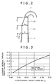
- Fig. 2 shows an enlarged cross-sectional shape of one diffuser of the single-shaft multi-stage centrifugal compressor in Fig. 1 .
- the diffuser has a first vaneless diffuser 21 with a constant flow channel height provided downstream from the impeller 1, and a second vaneless diffuser 22, in which the flow channel height decreases in the flow direction, provided downstream from the first vaneless diffuser 21.
- the return bend 3 to guide the working fluid to the next stage is provided downstream from the second vaneless diffuser 22.
- an inlet flow channel height b 1 and an outlet flow channel height b m are the same.
- the outlet of the first vaneless diffuser 21 is also used as an inlet of the second vaneless diffuser 22.
- an outlet flow channel height b o is lower than the inlet flow channel height b m , and the flow channel height in the second vaneless diffuser 22 becomes lower toward the downstream side.
- Fig. 3 shows a characteristic of a critical inflow angle ⁇ crt of a flow in a parallel wall vaneless diffuser shown in Fig. 4 .
- the inflow angle ⁇ is defined as an angle ⁇ at which the flow direction at the diffuser inlet (impeller outlet) is a tangent line direction.
- the lateral axis indicates a ratio b/r imp between the flow channel height b of the diffuser and the outlet radius r imp of the impeller, and the vertical axis, the diffuser critical inflow angle ⁇ crt as the limitation of occurrence of rotating stall.
- the characteristic diagram indicates that the diffuser critical inflow angle a crt becomes wider in accordance with increase in the diffuser flow channel height ratio b/r imp . In a diffuser with a flow channel height ratio b/r imp , when the inflow angle ⁇ is smaller than the critical inflow angle ⁇ crt shown in the figure, the rotating stall occurs.
- the rotating stall can be prevented by increasing the inflow angle to the diffuser.
- it may be arranged such that the diffuser inlet flow channel height is low and the longitudinal cross-sectional speed of the flow is high.
- the decrease in the diffuser inlet flow channel height on the immediately downstream side of the impeller outlet might increase frictional loss in the diffuser part and reduce the efficiency of the compressor.
- the first vaneless diffuser having a constant flow channel height is provided on the downstream side of the impeller, and the second vaneless diffuser where the flow channel height gradually decreases in the flow direction from the inlet to the outlet is provided on the downstream side of the first vaneless diffuser.
- the first vaneless diffuser with the constant flow channel height is a diffuser first half part on the immediately downstream side of the impeller, increase in the frictional loss can be prevented.
- the second vaneless diffuser where the flow channel height gradually decreases in the flow direction from the inlet to the outlet is a diffuser last half part, the flow angle is wide. Accordingly, development of boundary layer on wall surface is suppressed, and the flow is stabled. Thus reverse of the flow can be prevented, and the occurrence of rotating stall can be prevented.
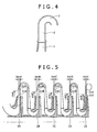
- Fig. 5 shows a second embodiment and shows a longitudinal cross-sectional shape of the single-shaft multi-stage centrifugal compressor.
- the diffuser of the centrifugal compressor has first vaneless diffusers 21A to 21E with a constant flow channel height and second vaneless diffusers 22A to 22E, in which the flow channel height decreases in the flow direction, provided downstream from the first vaneless diffusers.
- the outlet height of the impeller becomes lower in the downstream stages since the volume flow rate becomes smaller in the lower stage. Accordingly, the inlet flow channel heights b m A to b m E of the second vaneless diffusers 22A to 22E, in which the flow channel height gradually decreases in the flow direction from the inlet to the outlet in the respective stages, become lower in the downstream stages.
- the radial positions r m A to r m E of the inlets of the second vaneless diffusers are smaller in the downstream stages.
- an inlet radius ratio r m/ r imp as a ratio between an inlet radius r m of the second vaneless diffuser and the outlet radius r imp of the impeller becomes smaller in accordance with decrease in a flow channel height ratio b m /r imp as a ratio between the inlet flow channel height b m of the second vaneless diffuser and the outlet radius r imp of the impeller.
- a radial position r/ imp in which reverse flow occurs becomes smaller in accordance with decrease in the flow channel height ratio b/r imp . Accordingly, as the flow channel height ratio b/r imp is smaller, the inlet radius ratio r/r imp is smaller.
- the inlet radial position r m of the second vaneless diffuser in which the flow channel height decreases in the flow direction is reduced in accordance with decrease in the flow channel height ratio b/r imp , so as to increase the flow angle and prevent the occurrence of reverse flow, the occurrence of rotating stall can be prevented.
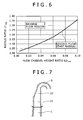
- Fig. 6 shows limitation of occurrence of reverse flow in the parallel wall vaneless diffuser shown in Fig. 4 .
- the lateral axis indicates the flow channel height ratio b/r imp of the diffuser, and the vertical axis, the ratio r/r imp between the radial position r in which a reverse flow occurs in the diffuser and the outlet radius r imp of the impeller.
- Fig. 6 shows that the minimum radial position r in which a reverse flow occurs becomes smaller in accordance with decrease in the flow channel height ratio b/r imp of the diffuser. It is considered that the rotating stall in the vaneless diffuser occurs due to development of the reverse flow.
- a diffuser drawing ratio is logically calculated from the result of measurement of the flow angle in the parallel wall vaneless diffuser, and based on the experimental measurement, the outlet flow channel height b o of the second vaneless diffuser in Fig. 2 is set to 0.4 to 0.6 times of the inlet flow channel height b m of the second vaneless diffuser.
- the inlet radius ratio r m /r imp of the second vaneless diffuser is given as a function of the flow channel height ratio b m /r imp of the second vaneless diffuser in the following expression (1).
- r m / r imp ⁇ 1.03 + 3.0 ⁇ b m / r imp
- the expression (1) is linear approximation of the relation between the flow channel height ratio b/r imp at which the rotating stall occurs and the radius ratio r/r imp in a position in which a reverse flow occurs as shown in Fig. 6 . That is, when the flow channel height b m is determined, a position in which a reverse flow occurs is obtained.
- the inlet radius position of the second vaneless diffuser is smaller than the radius position in which a reverse flow occurs, predicted by this expression, as the flow angle can be wider on the upstream side of the position in which the reverse flow occurs, the occurrence of rotating stall can be prevented.
- the inlet radius ratio r m /r imp of the second vaneless diffuser is smaller than the value determined with the expression (1), as the flow angle can be wider on the upstream side of the position in which the reverse flow occurs, the occurrence of rotating stall can be prevented.
- the characteristic feature of the fifth embodiment is that the flow channel height ratio b m/ r imp of the second vaneless diffuser in Fig. 6 is equal to or less than 0.1, because in a comparatively-low specific speed impeller stage in which the flow channel height ratio b m/ r imp is equal to or greater than 0.1, the occurrence of rotating stall is noticeable.
- Figs. 7 to 9 show sixth to eighth embodiments.
- the longitudinal cross-sectional shape of the second vaneless diffuser in which the flow channel height decreases in the flow direction consists of straight lines.
- the wall surface shape on the hub side (right side in the figure) of the second vaneless diffuser 22 is an extension of the first vaneless diffuser 21.
- the wall surface shape on the shroud side (left side in the figure) is inclined toward the hub side.
- the wall surface shape on the hub side is inclined toward the shroud side (left side in the figure).
- the wall surface shapes on the hub side and the shroud side in the second vaneless diffuser are inclined toward each other.
- Figs. 10 to 15 show ninth to fourteenth embodiments.
- the longitudinal cross-sectional shape of the second vaneless diffuser in which the flow channel height decreases in the flow direction includes a curve.
- the wall surface shape on the hub side (right side in the figure) of the second vaneless diffuser is an extension of the first vaneless diffuser.
- the wall surface shape on the shroud side is inclined toward the hub side.
- the shape includes a curve, and the outlet of the second vaneless diffuser is smoothly connected to the return bend inlet on the downstream side.
- the inlet of the second vaneless diffuser is smoothly connected to the outlet of the first vaneless diffuser.
- the wall surface shape on the hub side is included toward the shroud side.
- the wall surface shapes on the hub side and the shroud side in the second vaneless diffuser are inclined toward each other.
- the impellers 1 (1A to 1E) in the respective stages are impellers using wedge-shaped thick blades as shown in Fig. 16 .
- the first vaneless diffuser having a constant flow channel height is provided on the downstream side of the impeller, and the second vaneless diffuser in which the flow channel height decreases in the flow direction is provided downstream from the first vaneless diffuser.
- the performance of the impeller using the wedge-shaped thick blades is higher in comparison with a impeller using general thin blades.
Landscapes
- Engineering & Computer Science (AREA)
- Mechanical Engineering (AREA)
- General Engineering & Computer Science (AREA)
- Structures Of Non-Positive Displacement Pumps (AREA)
Abstract
Description
- The present invention relates to a centrifugal compressor and a diffuser used therein, and more particularly, to a centrifugal compressor and a centrifugal blower to handle comparatively low flow rate gas, and a diffuser used therein.
- In a high-pressure centrifugal compressor to handle high pressure gas, phenomena disturbing safe operation of the compressor such as noise, damage to an impeller, and vibration of shafting easily occur in comparison with a general centrifugal compressor. One of the phenomena is rotating stall.
- The rotating stall occurs mainly in a comparatively-low specific speed impeller stage. It is considered as the mechanism of the rotating stall that the rotating stall occurs due to a reverse flow which occurs in a flow in the diffuser. The flow in the diffuser is a deceleration flow, and separation of the flow from a wall surface easily occurs in accordance with inverse pressure gradient. This phenomenon easily occurs on the downstream side in accordance with increase in a ratio of a flow channel height of the diffuser to an outlet radius of an impeller. It is considered that the separation of the flow gradually increases, which leads to the rotating stall.
- In the centrifugal compressor in which the rotating stall may occur, a technique using a vaned diffuser is disclosed in International application
WO97/33092 - However, in the technique using the vaned diffuser as disclosed in the above-described International application
WO97/33092 - That is, in some cases, a comparatively-low specific speed (specific speed: about 200 and/or lower) impeller using wedge-shaped thick impeller blades is employed in a high-pressure comparatively-low specific speed centrifugal compressor. In a comparatively-low specific speed region, the performance of the thick blade impeller is greater than that of a general thin blade impeller. However, in the thick blade impeller, as the impeller height is higher in comparison with a thin blade impeller with the same flow rate, a radial component of the speed at a diffuser inlet is small. Accordingly, a flow angle is small. Further, by a wake flow from a trailing edge of the thick blade impeller, a flow at a small flow angle locally occurs in circumferential speed distribution at the impeller outlet. Accordingly, a reverse flow in the diffuser easily occurs in comparison with a thin blade impeller stage with the same flow rate. In this manner, in the conventional high pressure centrifugal compressor, prevention of rotating stall is not considered.
- The object of the present invention is, in a centrifugal compressor having an inlet flow channel, an impeller, a vaneless diffuser, and a return channel, to prevent rotating stall which noticeably occurs in a comparatively-low specific speed impeller stage, and to provide a high-performance and high-reliability high pressure centrifugal compressor.
- A centrifugal compressor according to the present invention comprises: a rotating shaft, an impeller attached to the rotating shaft; a vaneless diffuser provided on the downstream side of the impeller; an inlet flow channel; and a return channel. The vaneless diffuser has a first vaneless diffuser with a constant flow channel height provided on the downstream side of the impeller, and a second vaneless diffuser in which a flow channel height decreases in a flow direction from an inlet to an outlet, provided on the downstream side of the first vaneless diffuser.
- Further, in the second vaneless diffuser, an inlet radius ratio rm/rimp as a ratio between an inlet radius rm of the second vaneless diffuser and an outlet radius rimp of the impeller becomes smaller in accordance with decrease in a flow channel height ratio bm/rimp as a ratio between an inlet flow channel height bm of the second vaneless diffuser and the outlet radius rimp of the impeller.
- Further, an outlet flow channel height bo of the second vaneless diffuser is set to 0.4 to 0.6 times of the inlet flow channel height bm of the second vaneless diffuser. Further, the inlet radius ratio rm/rimp of the second vaneless diffuser is given as a function (rm/rimp≤1.03+3.0·bm/rimp) of the flow channel height ratio bm/rimp of the second vaneless diffuser.
- Further, the flow channel height ratio bm/rimp of the second vaneless diffuser is equal to or less than 0.1. Further, a longitudinal cross-sectional wall surface shape of the first and second vaneless diffusers consists of straight lines. Further, a wall surface shape in the longitudinal cross-sectional shape of the first and second vaneless diffusers includes a curve. Further, the centrifugal compressor further comprises an impeller having a wedge-shaped thick blades./in a centrifugal compressor comprising: an inlet flow channel; an impeller; a vaneless diffuser: and a return channel, the impeller has wedge-shaped thick blades.
- Further, a vaneless diffuser according to the present invention comprises: a first vaneless diffuser with a constant flow channel height; and a second vaneless diffuser, in which a flow channel height decreases in a flow direction from an inlet to an outlet, provided on the downstream side of the first vaneless diffuser.
- In the high pressure centrifugal compressor according to the present invention, the occurrence of rotating stall can be prevented with the vaneless diffuser. Further, the efficiency is higher in comparison with a vaneless diffuser in which the flow channel height in the diffuser gradually decreases from a diffuser inlet in a downstream direction. Further, by combining the diffuser with a impeller stage using thick blades, the efficiency can be improved while the occurrence of rotating stall is prevented.
-
-
Fig. 1 is a longitudinal cross-sectional view of a multi-stage centrifugal compressor according to a first embodiment of the present invention; -
Fig. 2 is an enlarged cross-sectional view of a diffuser part of the multi-stage centrifugal compressor inFig. 1 ; -
Fig. 3 is a graph showing a characteristic of a critical inflow angle of a flow in a parallel wall vaneless diffuser; -
Fig. 4 is a cross-sectional view of the parallel wall vaneless diffuser; -
Fig. 5 is a longitudinal cross-sectional view of the multi-stage centrifugal compressor according to a second embodiment of the present invention; -
Fig. 6 is a graph showing the relation between a flow channel height ratio and a radius ratio in a position where a reverse flow occurs; -
Figs. 7 to 15 are cross-sectional views of the vaneless diffuser according to sixth to fourteenth embodiments of the present invention; and -
Fig. 16 is a front view of an impeller using wedge-shaped thick blades according to a fifteenth embodiment of the present invention. - Hereinbelow, embodiments of the present invention will be described in detail using the accompanying drawings.
-
Fig. 1 shows a longitudinal cross-sectional shape of a single-shaft multi-stage centrifugal compressor according to a first embodiment of the present invention. A compressor stage havingplural impellers 1A to 1E,diffusers 2A to 2E, return bends (return channels) 3A to 3D, andguide blades 4A to 4D, is arranged in an axial direction, thereby a single-shaft multi-stagecentrifugal compressor 100 is formed. Theplural impellers 1A to 1E stacked in the axial direction are attached to a rotatingshaft 7, and both ends of the rotatingshaft 7 are rotatably supported withbearings 9. - The
diffusers 2A to 2E are provided on the outer side in the radial direction as a downstream side of therespective impellers 1A to 1E. Thediffusers 2A to 2D in the respective stages except the final stage are connected to thereturn bends 3A to 3D to guide working fluid to the next stage, and theguide blades 4A to 4D to guide the working fluid inwardly in the radial direction are formed on the downstream side of thereturn bends 3A to 3D. Ascroll 5 to collect the working fluid discharged from the impeller in the final stage and discharge the working fluid from a discharge pipe (not shown) is formed on the downstream side of thediffuser 2E in the final stage. - The
diffusers 2A to 2E, thereturn bends 3A to 3D, theguide blades 4A to 4D and thescroll 5 are stationary members, and are formed in acompressor casing 6. The working fluid sucked from aninlet 8 is pressure-increased with theimpeller 1A and thediffuser 2A in the first stage, then the flow direction of the working fluid is changed from radial outward direction to radial inward direction with thereturn bend 3A and theguide blade 4A, and is guided to the impeller in the second stage. Hereinbelow, this flow is repeated in the respective stages, thereby the fluid is sequentially pressure-increased, then through the diffuser in the final stage, then passed through thedischarge scroll 5 and is guided to the discharge pipe. -
Fig. 2 shows an enlarged cross-sectional shape of one diffuser of the single-shaft multi-stage centrifugal compressor inFig. 1 . The diffuser has a first vaneless diffuser 21 with a constant flow channel height provided downstream from theimpeller 1, and asecond vaneless diffuser 22, in which the flow channel height decreases in the flow direction, provided downstream from thefirst vaneless diffuser 21. Thereturn bend 3 to guide the working fluid to the next stage is provided downstream from thesecond vaneless diffuser 22. - In the
first vaneless diffuser 21, an inlet flow channel height b1 and an outlet flow channel height bm are the same. The outlet of thefirst vaneless diffuser 21 is also used as an inlet of thesecond vaneless diffuser 22. In thesecond vaneless diffuser 22, an outlet flow channel height bo is lower than the inlet flow channel height bm, and the flow channel height in thesecond vaneless diffuser 22 becomes lower toward the downstream side. By using this diffuser, the occurrence of rotating stall particularly noticeable in a comparatively-low specific speed stage can be prevented. This is achieved for the following reasons. -
Fig. 3 shows a characteristic of a critical inflow angle αcrt of a flow in a parallel wall vaneless diffuser shown inFig. 4 . The inflow angle α is defined as an angle α at which the flow direction at the diffuser inlet (impeller outlet) is a tangent line direction. The lateral axis indicates a ratio b/rimp between the flow channel height b of the diffuser and the outlet radius rimp of the impeller, and the vertical axis, the diffuser critical inflow angle αcrt as the limitation of occurrence of rotating stall. The characteristic diagram indicates that the diffuser critical inflow angle acrt becomes wider in accordance with increase in the diffuser flow channel height ratio b/rimp. In a diffuser with a flow channel height ratio b/rimp, when the inflow angle α is smaller than the critical inflow angle αcrt shown in the figure, the rotating stall occurs. - According to the above description, it is understood that the rotating stall can be prevented by increasing the inflow angle to the diffuser. For this purpose, it may be arranged such that the diffuser inlet flow channel height is low and the longitudinal cross-sectional speed of the flow is high. However, the decrease in the diffuser inlet flow channel height on the immediately downstream side of the impeller outlet might increase frictional loss in the diffuser part and reduce the efficiency of the compressor.
- In the present embodiment, the first vaneless diffuser having a constant flow channel height is provided on the downstream side of the impeller, and the second vaneless diffuser where the flow channel height gradually decreases in the flow direction from the inlet to the outlet is provided on the downstream side of the first vaneless diffuser. As the first vaneless diffuser with the constant flow channel height is a diffuser first half part on the immediately downstream side of the impeller, increase in the frictional loss can be prevented. Further, as the second vaneless diffuser where the flow channel height gradually decreases in the flow direction from the inlet to the outlet is a diffuser last half part, the flow angle is wide. Accordingly, development of boundary layer on wall surface is suppressed, and the flow is stabled. Thus reverse of the flow can be prevented, and the occurrence of rotating stall can be prevented.
-
Fig. 5 shows a second embodiment and shows a longitudinal cross-sectional shape of the single-shaft multi-stage centrifugal compressor. The diffuser of the centrifugal compressor hasfirst vaneless diffusers 21A to 21E with a constant flow channel height andsecond vaneless diffusers 22A to 22E, in which the flow channel height decreases in the flow direction, provided downstream from the first vaneless diffusers. - In this centrifugal compressor, the outlet height of the impeller becomes lower in the downstream stages since the volume flow rate becomes smaller in the lower stage. Accordingly, the inlet flow channel heights bmA to bmE of the
second vaneless diffusers 22A to 22E, in which the flow channel height gradually decreases in the flow direction from the inlet to the outlet in the respective stages, become lower in the downstream stages. The radial positions rmA to rmE of the inlets of the second vaneless diffusers are smaller in the downstream stages. That is, an inlet radius ratio rm/rimp as a ratio between an inlet radius rm of the second vaneless diffuser and the outlet radius rimp of the impeller becomes smaller in accordance with decrease in a flow channel height ratio bm/rimp as a ratio between the inlet flow channel height bm of the second vaneless diffuser and the outlet radius rimp of the impeller. - It is understood from
Fig. 6 that a radial position r/imp in which reverse flow occurs becomes smaller in accordance with decrease in the flow channel height ratio b/rimp. Accordingly, as the flow channel height ratio b/rimp is smaller, the inlet radius ratio r/rimp is smaller. For example, when the inlet radial position rm of the second vaneless diffuser in which the flow channel height decreases in the flow direction is reduced in accordance with decrease in the flow channel height ratio b/rimp, so as to increase the flow angle and prevent the occurrence of reverse flow, the occurrence of rotating stall can be prevented. - Further,
Fig. 6 shows limitation of occurrence of reverse flow in the parallel wall vaneless diffuser shown inFig. 4 . The lateral axis indicates the flow channel height ratio b/rimp of the diffuser, and the vertical axis, the ratio r/rimp between the radial position r in which a reverse flow occurs in the diffuser and the outlet radius rimp of the impeller.Fig. 6 shows that the minimum radial position r in which a reverse flow occurs becomes smaller in accordance with decrease in the flow channel height ratio b/rimp of the diffuser. It is considered that the rotating stall in the vaneless diffuser occurs due to development of the reverse flow. - As a third embodiment, a diffuser drawing ratio is logically calculated from the result of measurement of the flow angle in the parallel wall vaneless diffuser, and based on the experimental measurement, the outlet flow channel height bo of the second vaneless diffuser in
Fig. 2 is set to 0.4 to 0.6 times of the inlet flow channel height bm of the second vaneless diffuser. When the value of bo/bm is too large, the effect of decrease in the flow channel height is reduced, while when the value of bo/bm is too small, the flow velocity is too high and the frictional loss is increased. - As a fourth embodiment, in
Fig. 5 , the inlet radius ratio rm/rimp of the second vaneless diffuser is given as a function of the flow channel height ratio bm/rimp of the second vaneless diffuser in the following expression (1).
- The expression (1) is linear approximation of the relation between the flow channel height ratio b/rimp at which the rotating stall occurs and the radius ratio r/rimp in a position in which a reverse flow occurs as shown in
Fig. 6 . That is, when the flow channel height bm is determined, a position in which a reverse flow occurs is obtained. When the inlet radius position of the second vaneless diffuser is smaller than the radius position in which a reverse flow occurs, predicted by this expression, as the flow angle can be wider on the upstream side of the position in which the reverse flow occurs, the occurrence of rotating stall can be prevented. Further, when the inlet radius ratio rm/rimp of the second vaneless diffuser is smaller than the value determined with the expression (1), as the flow angle can be wider on the upstream side of the position in which the reverse flow occurs, the occurrence of rotating stall can be prevented. - The characteristic feature of the fifth embodiment is that the flow channel height ratio bm/rimp of the second vaneless diffuser in
Fig. 6 is equal to or less than 0.1, because in a comparatively-low specific speed impeller stage in which the flow channel height ratio bm/rimp is equal to or greater than 0.1, the occurrence of rotating stall is noticeable. -
Figs. 7 to 9 show sixth to eighth embodiments. In these embodiments, the longitudinal cross-sectional shape of the second vaneless diffuser in which the flow channel height decreases in the flow direction consists of straight lines. In the sixth embodiment shown inFig. 7 , the wall surface shape on the hub side (right side in the figure) of thesecond vaneless diffuser 22 is an extension of thefirst vaneless diffuser 21. The wall surface shape on the shroud side (left side in the figure) is inclined toward the hub side. - In the seventh embodiment shown in
Fig. 8 , opposite to the sixth embodiment inFig. 7 , the wall surface shape on the hub side (right side in the figure) is inclined toward the shroud side (left side in the figure). In the eighth embodiment shown inFig. 9 , the wall surface shapes on the hub side and the shroud side in the second vaneless diffuser are inclined toward each other. -
Figs. 10 to 15 show ninth to fourteenth embodiments. In these embodiments, the longitudinal cross-sectional shape of the second vaneless diffuser in which the flow channel height decreases in the flow direction includes a curve. In the ninth embodiment shown inFig. 10 , the wall surface shape on the hub side (right side in the figure) of the second vaneless diffuser is an extension of the first vaneless diffuser. The wall surface shape on the shroud side is inclined toward the hub side. The shape includes a curve, and the outlet of the second vaneless diffuser is smoothly connected to the return bend inlet on the downstream side. - In the tenth embodiment shown in
Fig. 11 , the inlet of the second vaneless diffuser is smoothly connected to the outlet of the first vaneless diffuser. In the eleventh and twelfth embodiments shown inFigs. 12 and 13 , opposite to the ninth and tenth embodiments shown inFigs. 10 and 11 , the wall surface shape on the hub side is included toward the shroud side. In the thirteenth and fourteenth embodiments shown inFigs. 14 and 15 , the wall surface shapes on the hub side and the shroud side in the second vaneless diffuser are inclined toward each other. - As a fifteenth embodiment, in the single-shaft multi-stage centrifugal compressor shown in
Fig. 1 , the impellers 1 (1A to 1E) in the respective stages are impellers using wedge-shaped thick blades as shown inFig. 16 . The first vaneless diffuser having a constant flow channel height is provided on the downstream side of the impeller, and the second vaneless diffuser in which the flow channel height decreases in the flow direction is provided downstream from the first vaneless diffuser. In a comparatively-low specific speed region, the performance of the impeller using the wedge-shaped thick blades is higher in comparison with a impeller using general thin blades. In the thick blade impeller, as the outlet flow channel height is greater in comparison with a thin blade impeller with the same flow rate, a reverse flow easily occurs even when the flow angle is comparatively wide. Accordingly, a high effect of preventing the rotating stall by the vaneless diffuser can be produced.
Claims (9)
- A centrifugal compressor comprising:a rotating shaft,an impeller attached to the rotating shaft;a vaneless diffuser provided on the downstream side of the impeller;an inlet flow channel; anda return channel,wherein the vaneless diffuser has a first vaneless diffuser with a constant flow channel height provided on the downstream side of the impeller, and a second vaneless diffuser in which a flow channel height decreases in a flow direction from an inlet to an outlet, provided on the downstream side of the first vaneless diffuser.
- The centrifugal compressor according to claim 1, wherein the impeller, the vaneless diffuser, the inlet flow channel and the return channel are respectively provided in a plurality of positions, thereby a multi-stage centrifugal compressor is formed,
and wherein an inlet radius ratio rm/rimp as a ratio between an inlet radius rm of the second vaneless diffuser and an outlet radius rimp of the impeller becomes smaller in accordance with decrease in a flow channel height ratio bm/rimp as a ratio between an inlet flow channel height bm of the second vaneless diffuser and the outlet radius rimp of the impeller. - The centrifugal compressor according to claim 2, wherein an outlet flow channel height bo of the second vaneless diffuser is set to 0.4 to 0.6 times of the inlet flow channel height bm of the second vaneless diffuser.
- The centrifugal compressor according to claim 2, wherein the inlet radius ratio rm/rimp of the second vaneless diffuser is given as a function (rm/rimp≤1.03+3.0·bm/rimp) of the flow channel height ratio bm/rimp of the second vaneless diffuser.
- The centrifugal compressor according to claim 4, wherein the flow channel height ratio bm/rimp of the second vaneless diffuser is equal to or less than 0.1.
- The centrifugal compressor according to claim 2, wherein a longitudinal cross-sectional shape of the first and second vaneless diffusers consists straight lines.
- The centrifugal compressor according to claim 2, wherein a longitudinal cross-sectional shape of the first and second vaneless diffusers includes a curve.
- A centrifugal compressor comprises an impeller having a wedge-shaped thick blades in a centrifugal compressor comprising an inlet flow channel, an impeller, a vaneless diffuser: and a return channel, wherein the vaneless diffuser has a first vaneless diffuser with a constant flow channel height provided on the downstream side of the impeller, and a second vaneless diffuser in which a flow channel height decreases in a flow direction from an inlet to an outlet, provided on the downstream side of the first vaneless diffuser.
- A vaneless diffuser for a centrifugal compressor, comprising:a first vaneless diffuser with a constant flow channel height; anda second vaneless diffuser, in which a flow channel height decreases in a flow direction from an inlet to an outlet, provided on the downstream side of the first vaneless diffuser.
Applications Claiming Priority (1)
| Application Number | Priority Date | Filing Date | Title |
|---|---|---|---|
| JP2008162882A JP5233436B2 (en) | 2008-06-23 | 2008-06-23 | Centrifugal compressor with vaneless diffuser and vaneless diffuser |
Publications (3)
| Publication Number | Publication Date |
|---|---|
| EP2138724A2 true EP2138724A2 (en) | 2009-12-30 |
| EP2138724A3 EP2138724A3 (en) | 2011-03-02 |
| EP2138724B1 EP2138724B1 (en) | 2014-03-19 |
Family
ID=40934206
Family Applications (1)
| Application Number | Title | Priority Date | Filing Date |
|---|---|---|---|
| EP09007940.1A Not-in-force EP2138724B1 (en) | 2008-06-23 | 2009-06-17 | Centrifugal compressor having vaneless diffuser and vaneless diffuser thereof |
Country Status (3)
| Country | Link |
|---|---|
| US (1) | US8313290B2 (en) |
| EP (1) | EP2138724B1 (en) |
| JP (1) | JP5233436B2 (en) |
Cited By (2)
| Publication number | Priority date | Publication date | Assignee | Title |
|---|---|---|---|---|
| RU2511907C1 (en) * | 2012-12-27 | 2014-04-10 | Закрытое акционерное общество "Научно-исследовательский и конструкторский институт центробежных и роторных компрессоров им. В.Б. Шнеппа" | Adjustable diffuser of centrifugal compressor |
| CN104343725A (en) * | 2013-07-23 | 2015-02-11 | 沈阳透平机械股份有限公司 | MCL compressor model level and design method thereof |
Families Citing this family (22)
| Publication number | Priority date | Publication date | Assignee | Title |
|---|---|---|---|---|
| CN102182710B (en) * | 2011-03-23 | 2013-07-17 | 清华大学 | Centrifugal compressor with asymmetrical vane-less diffusers and producing method thereof |
| WO2014203379A1 (en) * | 2013-06-20 | 2014-12-24 | 三菱重工業株式会社 | Centrifugal compressor |
| US10375901B2 (en) | 2014-12-09 | 2019-08-13 | Mtd Products Inc | Blower/vacuum |
| US20160281727A1 (en) * | 2015-03-27 | 2016-09-29 | Dresser-Rand Company | Apparatus, system, and method for compressing a process fluid |
| RU2584224C1 (en) * | 2015-06-18 | 2016-05-20 | Закрытое акционерное общество "Научно-исследовательский и конструкторский институт центробежных и роторных компрессоров им. В.Б. Шнеппа" | Centrifugal compressor |
| EP3248877B1 (en) | 2016-05-26 | 2023-05-10 | Hamilton Sundstrand Corporation | Mixing bleed and ram air at a turbine inlet |
| US10604263B2 (en) | 2016-05-26 | 2020-03-31 | Hamilton Sundstrand Corporation | Mixing bleed and ram air using a dual use turbine system |
| EP3248879B1 (en) | 2016-05-26 | 2021-06-30 | Hamilton Sundstrand Corporation | Mixing bleed and ram air using an air cycle machine with two turbines |
| US10773807B2 (en) | 2016-05-26 | 2020-09-15 | Hamilton Sunstrand Corporation | Energy flow of an advanced environmental control system |
| EP3254970B1 (en) | 2016-05-26 | 2020-04-29 | Hamilton Sundstrand Corporation | An environmental control system with an outflow heat exchanger |
| US11047237B2 (en) * | 2016-05-26 | 2021-06-29 | Hamilton Sunstrand Corporation | Mixing ram and bleed air in a dual entry turbine system |
| US11511867B2 (en) | 2016-05-26 | 2022-11-29 | Hamilton Sundstrand Corporation | Mixing ram and bleed air in a dual entry turbine system |
| US11506121B2 (en) | 2016-05-26 | 2022-11-22 | Hamilton Sundstrand Corporation | Multiple nozzle configurations for a turbine of an environmental control system |
| BR102017010900B1 (en) | 2016-05-26 | 2023-04-04 | Hamilton Sundstrand Corporation | COMPRESSION DEVICE AND ENVIRONMENTAL CONTROL SYSTEM OF AN AIRCRAFT |
| DE102016217446A1 (en) * | 2016-09-13 | 2018-03-15 | Bosch Mahle Turbo Systems Gmbh & Co. Kg | loader |
| JP7013316B2 (en) * | 2018-04-26 | 2022-01-31 | 三菱重工コンプレッサ株式会社 | Centrifugal compressor |
| CN109214141B (en) * | 2018-11-20 | 2022-05-27 | 西华大学 | Rotating stall prediction method and device |
| US20200378303A1 (en) * | 2019-06-03 | 2020-12-03 | Pratt & Whitney Canada Corp. | Diffuser pipe exit flare |
| EP3686436A1 (en) * | 2019-07-31 | 2020-07-29 | Sulzer Management AG | Multistage pump and subsea pumping arrangement |
| IT202000001216A1 (en) * | 2020-01-22 | 2021-07-22 | Nuovo Pignone Tecnologie Srl | A DIFFUSER WITH NOT CONSTANT DIFFUSER BLADES PITCH AND CENTRIFUGAL TURBOMACHINE INCLUDING SAID DIFFUSER |
| WO2021148239A1 (en) | 2020-01-23 | 2021-07-29 | Nuovo Pignone Tecnologie - S.R.L. | A return channel with non-constant return channel vanes pitch and centrifugal turbomachine including said return channel |
| US20250354565A1 (en) * | 2024-05-20 | 2025-11-20 | Borgwarner Inc. | Controlled Area Progression Vaned Diffuser |
Citations (1)
| Publication number | Priority date | Publication date | Assignee | Title |
|---|---|---|---|---|
| WO1997033092A1 (en) | 1996-03-06 | 1997-09-12 | Hitachi, Ltd. | Centrifugal compressor and diffuser for the centrifugal compressor |
Family Cites Families (6)
| Publication number | Priority date | Publication date | Assignee | Title |
|---|---|---|---|---|
| US3289921A (en) * | 1965-10-08 | 1966-12-06 | Caterpillar Tractor Co | Vaneless diffuser |
| JPS54161007U (en) * | 1978-04-28 | 1979-11-10 | ||
| JPH01173426U (en) * | 1988-05-26 | 1989-12-08 | ||
| JP2751418B2 (en) * | 1989-06-13 | 1998-05-18 | ダイキン工業株式会社 | Turbo compressor diffuser |
| JP3036220B2 (en) * | 1992-04-06 | 2000-04-24 | 株式会社日立製作所 | Centrifugal compressor |
| JP2008075536A (en) * | 2006-09-21 | 2008-04-03 | Mitsubishi Heavy Ind Ltd | Centrifugal compressor |
-
2008
- 2008-06-23 JP JP2008162882A patent/JP5233436B2/en active Active
-
2009
- 2009-06-17 EP EP09007940.1A patent/EP2138724B1/en not_active Not-in-force
- 2009-06-22 US US12/488,910 patent/US8313290B2/en not_active Expired - Fee Related
Patent Citations (1)
| Publication number | Priority date | Publication date | Assignee | Title |
|---|---|---|---|---|
| WO1997033092A1 (en) | 1996-03-06 | 1997-09-12 | Hitachi, Ltd. | Centrifugal compressor and diffuser for the centrifugal compressor |
Cited By (2)
| Publication number | Priority date | Publication date | Assignee | Title |
|---|---|---|---|---|
| RU2511907C1 (en) * | 2012-12-27 | 2014-04-10 | Закрытое акционерное общество "Научно-исследовательский и конструкторский институт центробежных и роторных компрессоров им. В.Б. Шнеппа" | Adjustable diffuser of centrifugal compressor |
| CN104343725A (en) * | 2013-07-23 | 2015-02-11 | 沈阳透平机械股份有限公司 | MCL compressor model level and design method thereof |
Also Published As
| Publication number | Publication date |
|---|---|
| EP2138724A3 (en) | 2011-03-02 |
| US8313290B2 (en) | 2012-11-20 |
| JP2010001851A (en) | 2010-01-07 |
| JP5233436B2 (en) | 2013-07-10 |
| EP2138724B1 (en) | 2014-03-19 |
| US20090317248A1 (en) | 2009-12-24 |
Similar Documents
| Publication | Publication Date | Title |
|---|---|---|
| EP2138724B1 (en) | Centrifugal compressor having vaneless diffuser and vaneless diffuser thereof | |
| JP5879103B2 (en) | Centrifugal fluid machine | |
| EP2020509B1 (en) | Centrifugal compressor, impeller and operating method of the same | |
| US6203275B1 (en) | Centrifugal compressor and diffuser for centrifugal compressor | |
| RU2581686C2 (en) | Radial diffuser blade for centrifugal compressors | |
| JP5316365B2 (en) | Turbo fluid machine | |
| JPWO1997033092A1 (en) | Centrifugal compressors and diffusers for centrifugal compressors | |
| US8287236B2 (en) | Multistage centrifugal compressor | |
| KR101226363B1 (en) | Centrifugal compressor | |
| CN103998790A (en) | Centrifugal compressor | |
| JP3557389B2 (en) | Multistage centrifugal compressor | |
| JP2010031777A (en) | Multistage centrifugal compressor | |
| JP6064003B2 (en) | Centrifugal fluid machine | |
| JPH03264796A (en) | Mixed flow compressor | |
| US20120183395A1 (en) | Radial compressor diffuser | |
| EP4299917A1 (en) | Multistage centrifugal compressor | |
| JPH1182389A (en) | Turbo type fluid machine | |
| JPH11257291A (en) | Centrifugal compressor diffuser | |
| EP1682779B1 (en) | Radial compressor impeller | |
| JPH0278794A (en) | Mixed flow type compressor | |
| JP2023001450A (en) | multistage centrifugal fluid machine | |
| JP5875429B2 (en) | Multistage centrifugal blower | |
| JPH0763197A (en) | Centrifugal fluid machine |
Legal Events
| Date | Code | Title | Description |
|---|---|---|---|
| PUAI | Public reference made under article 153(3) epc to a published international application that has entered the european phase |
Free format text: ORIGINAL CODE: 0009012 |
|
| 17P | Request for examination filed |
Effective date: 20090617 |
|
| AK | Designated contracting states |
Kind code of ref document: A2 Designated state(s): AT BE BG CH CY CZ DE DK EE ES FI FR GB GR HR HU IE IS IT LI LT LU LV MC MK MT NL NO PL PT RO SE SI SK TR |
|
| RTI1 | Title (correction) |
Free format text: CENTRIFUGAL COMPRESSOR HAVING VANELESS DIFFUSER AND VANELESS DIFFUSER THEREOF |
|
| PUAL | Search report despatched |
Free format text: ORIGINAL CODE: 0009013 |
|
| AK | Designated contracting states |
Kind code of ref document: A3 Designated state(s): AT BE BG CH CY CZ DE DK EE ES FI FR GB GR HR HU IE IS IT LI LT LU LV MC MK MT NL NO PL PT RO SE SI SK TR |
|
| AX | Request for extension of the european patent |
Extension state: AL BA RS |
|
| RIC1 | Information provided on ipc code assigned before grant |
Ipc: F04D 29/44 20060101AFI20110125BHEP |
|
| REG | Reference to a national code |
Ref country code: DE Ref legal event code: R079 Ref document number: 602009022545 Country of ref document: DE Free format text: PREVIOUS MAIN CLASS: F04D0017120000 Ipc: F04D0029440000 |
|
| RIC1 | Information provided on ipc code assigned before grant |
Ipc: F04D 29/44 20060101AFI20130902BHEP |
|
| GRAP | Despatch of communication of intention to grant a patent |
Free format text: ORIGINAL CODE: EPIDOSNIGR1 |
|
| RAP1 | Party data changed (applicant data changed or rights of an application transferred) |
Owner name: HITACHI PLANT TECHNOLOGIES, LTD. |
|
| INTG | Intention to grant announced |
Effective date: 20131015 |
|
| GRAS | Grant fee paid |
Free format text: ORIGINAL CODE: EPIDOSNIGR3 |
|
| GRAA | (expected) grant |
Free format text: ORIGINAL CODE: 0009210 |
|
| RAP1 | Party data changed (applicant data changed or rights of an application transferred) |
Owner name: HITACHI, LTD. |
|
| AK | Designated contracting states |
Kind code of ref document: B1 Designated state(s): AT BE BG CH CY CZ DE DK EE ES FI FR GB GR HR HU IE IS IT LI LT LU LV MC MK MT NL NO PL PT RO SE SI SK TR |
|
| REG | Reference to a national code |
Ref country code: GB Ref legal event code: FG4D |
|
| REG | Reference to a national code |
Ref country code: CH Ref legal event code: NV Representative=s name: TROESCH SCHEIDEGGER WERNER AG, CH Ref country code: CH Ref legal event code: EP |
|
| REG | Reference to a national code |
Ref country code: IE Ref legal event code: FG4D |
|
| REG | Reference to a national code |
Ref country code: AT Ref legal event code: REF Ref document number: 657853 Country of ref document: AT Kind code of ref document: T Effective date: 20140415 |
|
| REG | Reference to a national code |
Ref country code: DE Ref legal event code: R096 Ref document number: 602009022545 Country of ref document: DE Effective date: 20140430 |
|
| PG25 | Lapsed in a contracting state [announced via postgrant information from national office to epo] |
Ref country code: NO Free format text: LAPSE BECAUSE OF FAILURE TO SUBMIT A TRANSLATION OF THE DESCRIPTION OR TO PAY THE FEE WITHIN THE PRESCRIBED TIME-LIMIT Effective date: 20140619 Ref country code: LT Free format text: LAPSE BECAUSE OF FAILURE TO SUBMIT A TRANSLATION OF THE DESCRIPTION OR TO PAY THE FEE WITHIN THE PRESCRIBED TIME-LIMIT Effective date: 20140319 |
|
| REG | Reference to a national code |
Ref country code: NL Ref legal event code: VDEP Effective date: 20140319 |
|
| REG | Reference to a national code |
Ref country code: AT Ref legal event code: MK05 Ref document number: 657853 Country of ref document: AT Kind code of ref document: T Effective date: 20140319 |
|
| REG | Reference to a national code |
Ref country code: LT Ref legal event code: MG4D |
|
| PG25 | Lapsed in a contracting state [announced via postgrant information from national office to epo] |
Ref country code: CY Free format text: LAPSE BECAUSE OF FAILURE TO SUBMIT A TRANSLATION OF THE DESCRIPTION OR TO PAY THE FEE WITHIN THE PRESCRIBED TIME-LIMIT Effective date: 20140319 Ref country code: FI Free format text: LAPSE BECAUSE OF FAILURE TO SUBMIT A TRANSLATION OF THE DESCRIPTION OR TO PAY THE FEE WITHIN THE PRESCRIBED TIME-LIMIT Effective date: 20140319 Ref country code: SE Free format text: LAPSE BECAUSE OF FAILURE TO SUBMIT A TRANSLATION OF THE DESCRIPTION OR TO PAY THE FEE WITHIN THE PRESCRIBED TIME-LIMIT Effective date: 20140319 |
|
| PG25 | Lapsed in a contracting state [announced via postgrant information from national office to epo] |
Ref country code: LV Free format text: LAPSE BECAUSE OF FAILURE TO SUBMIT A TRANSLATION OF THE DESCRIPTION OR TO PAY THE FEE WITHIN THE PRESCRIBED TIME-LIMIT Effective date: 20140319 Ref country code: HR Free format text: LAPSE BECAUSE OF FAILURE TO SUBMIT A TRANSLATION OF THE DESCRIPTION OR TO PAY THE FEE WITHIN THE PRESCRIBED TIME-LIMIT Effective date: 20140319 |
|
| PG25 | Lapsed in a contracting state [announced via postgrant information from national office to epo] |
Ref country code: IS Free format text: LAPSE BECAUSE OF FAILURE TO SUBMIT A TRANSLATION OF THE DESCRIPTION OR TO PAY THE FEE WITHIN THE PRESCRIBED TIME-LIMIT Effective date: 20140719 Ref country code: RO Free format text: LAPSE BECAUSE OF FAILURE TO SUBMIT A TRANSLATION OF THE DESCRIPTION OR TO PAY THE FEE WITHIN THE PRESCRIBED TIME-LIMIT Effective date: 20140319 Ref country code: CZ Free format text: LAPSE BECAUSE OF FAILURE TO SUBMIT A TRANSLATION OF THE DESCRIPTION OR TO PAY THE FEE WITHIN THE PRESCRIBED TIME-LIMIT Effective date: 20140319 Ref country code: NL Free format text: LAPSE BECAUSE OF FAILURE TO SUBMIT A TRANSLATION OF THE DESCRIPTION OR TO PAY THE FEE WITHIN THE PRESCRIBED TIME-LIMIT Effective date: 20140319 Ref country code: BG Free format text: LAPSE BECAUSE OF FAILURE TO SUBMIT A TRANSLATION OF THE DESCRIPTION OR TO PAY THE FEE WITHIN THE PRESCRIBED TIME-LIMIT Effective date: 20140619 Ref country code: EE Free format text: LAPSE BECAUSE OF FAILURE TO SUBMIT A TRANSLATION OF THE DESCRIPTION OR TO PAY THE FEE WITHIN THE PRESCRIBED TIME-LIMIT Effective date: 20140319 Ref country code: BE Free format text: LAPSE BECAUSE OF FAILURE TO SUBMIT A TRANSLATION OF THE DESCRIPTION OR TO PAY THE FEE WITHIN THE PRESCRIBED TIME-LIMIT Effective date: 20140319 |
|
| PG25 | Lapsed in a contracting state [announced via postgrant information from national office to epo] |
Ref country code: SK Free format text: LAPSE BECAUSE OF FAILURE TO SUBMIT A TRANSLATION OF THE DESCRIPTION OR TO PAY THE FEE WITHIN THE PRESCRIBED TIME-LIMIT Effective date: 20140319 Ref country code: ES Free format text: LAPSE BECAUSE OF FAILURE TO SUBMIT A TRANSLATION OF THE DESCRIPTION OR TO PAY THE FEE WITHIN THE PRESCRIBED TIME-LIMIT Effective date: 20140319 Ref country code: AT Free format text: LAPSE BECAUSE OF FAILURE TO SUBMIT A TRANSLATION OF THE DESCRIPTION OR TO PAY THE FEE WITHIN THE PRESCRIBED TIME-LIMIT Effective date: 20140319 Ref country code: PL Free format text: LAPSE BECAUSE OF FAILURE TO SUBMIT A TRANSLATION OF THE DESCRIPTION OR TO PAY THE FEE WITHIN THE PRESCRIBED TIME-LIMIT Effective date: 20140319 |
|
| REG | Reference to a national code |
Ref country code: DE Ref legal event code: R097 Ref document number: 602009022545 Country of ref document: DE |
|
| PG25 | Lapsed in a contracting state [announced via postgrant information from national office to epo] |
Ref country code: PT Free format text: LAPSE BECAUSE OF FAILURE TO SUBMIT A TRANSLATION OF THE DESCRIPTION OR TO PAY THE FEE WITHIN THE PRESCRIBED TIME-LIMIT Effective date: 20140721 |
|
| PLBE | No opposition filed within time limit |
Free format text: ORIGINAL CODE: 0009261 |
|
| STAA | Information on the status of an ep patent application or granted ep patent |
Free format text: STATUS: NO OPPOSITION FILED WITHIN TIME LIMIT |
|
| PG25 | Lapsed in a contracting state [announced via postgrant information from national office to epo] |
Ref country code: MC Free format text: LAPSE BECAUSE OF FAILURE TO SUBMIT A TRANSLATION OF THE DESCRIPTION OR TO PAY THE FEE WITHIN THE PRESCRIBED TIME-LIMIT Effective date: 20140319 Ref country code: DK Free format text: LAPSE BECAUSE OF FAILURE TO SUBMIT A TRANSLATION OF THE DESCRIPTION OR TO PAY THE FEE WITHIN THE PRESCRIBED TIME-LIMIT Effective date: 20140319 Ref country code: LU Free format text: LAPSE BECAUSE OF FAILURE TO SUBMIT A TRANSLATION OF THE DESCRIPTION OR TO PAY THE FEE WITHIN THE PRESCRIBED TIME-LIMIT Effective date: 20140617 |
|
| 26N | No opposition filed |
Effective date: 20141222 |
|
| GBPC | Gb: european patent ceased through non-payment of renewal fee |
Effective date: 20140619 |
|
| REG | Reference to a national code |
Ref country code: IE Ref legal event code: MM4A |
|
| REG | Reference to a national code |
Ref country code: FR Ref legal event code: ST Effective date: 20150227 |
|
| PG25 | Lapsed in a contracting state [announced via postgrant information from national office to epo] |
Ref country code: IT Free format text: LAPSE BECAUSE OF FAILURE TO SUBMIT A TRANSLATION OF THE DESCRIPTION OR TO PAY THE FEE WITHIN THE PRESCRIBED TIME-LIMIT Effective date: 20140319 |
|
| REG | Reference to a national code |
Ref country code: DE Ref legal event code: R097 Ref document number: 602009022545 Country of ref document: DE Effective date: 20141222 |
|
| PG25 | Lapsed in a contracting state [announced via postgrant information from national office to epo] |
Ref country code: IE Free format text: LAPSE BECAUSE OF NON-PAYMENT OF DUE FEES Effective date: 20140617 |
|
| PG25 | Lapsed in a contracting state [announced via postgrant information from national office to epo] |
Ref country code: FR Free format text: LAPSE BECAUSE OF NON-PAYMENT OF DUE FEES Effective date: 20140630 Ref country code: GB Free format text: LAPSE BECAUSE OF NON-PAYMENT OF DUE FEES Effective date: 20140619 |
|
| PG25 | Lapsed in a contracting state [announced via postgrant information from national office to epo] |
Ref country code: SI Free format text: LAPSE BECAUSE OF FAILURE TO SUBMIT A TRANSLATION OF THE DESCRIPTION OR TO PAY THE FEE WITHIN THE PRESCRIBED TIME-LIMIT Effective date: 20140319 |
|
| PG25 | Lapsed in a contracting state [announced via postgrant information from national office to epo] |
Ref country code: MT Free format text: LAPSE BECAUSE OF FAILURE TO SUBMIT A TRANSLATION OF THE DESCRIPTION OR TO PAY THE FEE WITHIN THE PRESCRIBED TIME-LIMIT Effective date: 20140319 |
|
| PG25 | Lapsed in a contracting state [announced via postgrant information from national office to epo] |
Ref country code: GR Free format text: LAPSE BECAUSE OF FAILURE TO SUBMIT A TRANSLATION OF THE DESCRIPTION OR TO PAY THE FEE WITHIN THE PRESCRIBED TIME-LIMIT Effective date: 20140620 |
|
| PG25 | Lapsed in a contracting state [announced via postgrant information from national office to epo] |
Ref country code: HU Free format text: LAPSE BECAUSE OF FAILURE TO SUBMIT A TRANSLATION OF THE DESCRIPTION OR TO PAY THE FEE WITHIN THE PRESCRIBED TIME-LIMIT; INVALID AB INITIO Effective date: 20090617 Ref country code: TR Free format text: LAPSE BECAUSE OF FAILURE TO SUBMIT A TRANSLATION OF THE DESCRIPTION OR TO PAY THE FEE WITHIN THE PRESCRIBED TIME-LIMIT Effective date: 20140319 |
|
| PGFP | Annual fee paid to national office [announced via postgrant information from national office to epo] |
Ref country code: CH Payment date: 20160613 Year of fee payment: 8 |
|
| REG | Reference to a national code |
Ref country code: CH Ref legal event code: PL |
|
| PG25 | Lapsed in a contracting state [announced via postgrant information from national office to epo] |
Ref country code: CH Free format text: LAPSE BECAUSE OF NON-PAYMENT OF DUE FEES Effective date: 20170630 Ref country code: LI Free format text: LAPSE BECAUSE OF NON-PAYMENT OF DUE FEES Effective date: 20170630 |
|
| PG25 | Lapsed in a contracting state [announced via postgrant information from national office to epo] |
Ref country code: MK Free format text: LAPSE BECAUSE OF FAILURE TO SUBMIT A TRANSLATION OF THE DESCRIPTION OR TO PAY THE FEE WITHIN THE PRESCRIBED TIME-LIMIT Effective date: 20140319 |
|
| PGFP | Annual fee paid to national office [announced via postgrant information from national office to epo] |
Ref country code: DE Payment date: 20180605 Year of fee payment: 10 |
|
| REG | Reference to a national code |
Ref country code: DE Ref legal event code: R119 Ref document number: 602009022545 Country of ref document: DE |
|
| PG25 | Lapsed in a contracting state [announced via postgrant information from national office to epo] |
Ref country code: DE Free format text: LAPSE BECAUSE OF NON-PAYMENT OF DUE FEES Effective date: 20200101 |