EP2138718A2 - Variable flow pumping system - Google Patents
Variable flow pumping system Download PDFInfo
- Publication number
- EP2138718A2 EP2138718A2 EP09250571A EP09250571A EP2138718A2 EP 2138718 A2 EP2138718 A2 EP 2138718A2 EP 09250571 A EP09250571 A EP 09250571A EP 09250571 A EP09250571 A EP 09250571A EP 2138718 A2 EP2138718 A2 EP 2138718A2
- Authority
- EP
- European Patent Office
- Prior art keywords
- pump
- lead screw
- fluid
- displacement
- selection controller
- Prior art date
- Legal status (The legal status is an assumption and is not a legal conclusion. Google has not performed a legal analysis and makes no representation as to the accuracy of the status listed.)
- Withdrawn
Links
Images



Classifications
-
- F—MECHANICAL ENGINEERING; LIGHTING; HEATING; WEAPONS; BLASTING
- F04—POSITIVE - DISPLACEMENT MACHINES FOR LIQUIDS; PUMPS FOR LIQUIDS OR ELASTIC FLUIDS
- F04C—ROTARY-PISTON, OR OSCILLATING-PISTON, POSITIVE-DISPLACEMENT MACHINES FOR LIQUIDS; ROTARY-PISTON, OR OSCILLATING-PISTON, POSITIVE-DISPLACEMENT PUMPS
- F04C14/00—Control of, monitoring of, or safety arrangements for, machines, pumps or pumping installations
- F04C14/18—Control of, monitoring of, or safety arrangements for, machines, pumps or pumping installations characterised by varying the volume of the working chamber
- F04C14/22—Control of, monitoring of, or safety arrangements for, machines, pumps or pumping installations characterised by varying the volume of the working chamber by changing the eccentricity between cooperating members
-
- F—MECHANICAL ENGINEERING; LIGHTING; HEATING; WEAPONS; BLASTING
- F04—POSITIVE - DISPLACEMENT MACHINES FOR LIQUIDS; PUMPS FOR LIQUIDS OR ELASTIC FLUIDS
- F04B—POSITIVE-DISPLACEMENT MACHINES FOR LIQUIDS; PUMPS
- F04B1/00—Multi-cylinder machines or pumps characterised by number or arrangement of cylinders
- F04B1/04—Multi-cylinder machines or pumps characterised by number or arrangement of cylinders having cylinders in star- or fan-arrangement
- F04B1/06—Control
- F04B1/07—Control by varying the relative eccentricity between two members, e.g. a cam and a drive shaft
Definitions
- the present invention relates to control of the operation of rotary positive displacement fluid pumps and, more particularly, to control of the operation of variable flow rate rotary positive displacement fluid pumps.
- Rotary positive displacement fluid pumps are operated relatively simply by connecting the pump rotor to a source of mechanical torque, typically an electric motor or an engine, either directly or through some kind of a mechanical interconnection arrangement such as gears.
- the resulting rotation rate of the pump rotor determines the volume of the pump output fluid flow, and so a substantially constant engine rotation rate leads to a substantially constant pump output fluid flow rate.
- a pumping arrangement for providing fuel to gas turbine engines has been common in the past with the mechanical torque source having been a shaft extending to the pump rotor from the accessory gearbox of the gas turbine engine receiving the flow of fuel from the pump.
- gas turbine engines used in aircraft operate over a rather large range of engine rotation rates in rotating the gears in its accessory gearbox, and so often, at greater engine rotation rates, such engines cause the fuel supplied thereto by the corresponding fuel pump formed by a rotary positive displacement fluid pump to be in quantities that are substantially in excess of that needed to fuel operation of the engine.
- the excess fuel is typically recirculated back to a location in the fuel delivery system ahead of the fuel pump inlet.
- Such pressurizing of the fuel by the pump, and then the subsequent depressurizing thereof in returning that excess fuel to ahead of the pump inlet, more or less continually over a span of time causes the fuel to become significantly heated.
- the ensuing large fuel temperature increases have various detrimental effects with respect to operation of the turbine engine.
- variable flow rate control of rotary positive displacement fluid pumps in such a manner as make the pump output flow rate much less dependent on the rotation rate of the pump rotor, and so much less dependent on the rotation rates in the accessory gearbox of the gas turbine engines to which they are correspondingly supplying fuel.
- a vane pump is used as a rotary positive displacement fluid pump serving as the fuel pump in which the pump displacement can be varied, as well as the rotation rate of the pump rotor, to together determine the pump output flow rate.
- the variation of pump displacement can be achieved, for example, by changing the relative position of typically, a cam and the pump rotor within which that pump rotor is mounted off center to move cycloidally with respect thereto.
- a reciprocating piston pump with a variable position swash plate can be used to provide a variable rotation rate, variable displacement pump for a fuel pump.
- Relatively elaborate hydraulic pump control systems use the fuel as the "working fluid" in the control system, i.e. a “fueldraulics" control system, as well as that fluid being supplied by the pump and its control system to the corresponding gas turbine engine to be the engine fuel therefor.
- FIG. 1 Such a pump displacement (and so pump output flow rate) control system and vane pump arrangement, 10, is shown in a schematic representation block diagram in Figure 1 .
- a vane pump, 11, is shown with an inlet, 12, to which fuel is supplied through an inlet pressure source, 12', and the pump is also is connected to a shaft, 13, to which torque for rotating the pump rotor is supplied as a result of this shaft extending to the accessory gearbox of a gas turbine engine (not shown).
- Vane pump 11 has an outlet, 14, from which fuel pressurized by this pump is provided both to a pressured fluid conduit, 15, to a metering valve, 16, and an excess flow bypass conduit, 17.
- Valve 16 in cooperation with a regulator, 18, operates to provide the desired rate of fuel flow at its outlet, 19, to the gas turbine engine combustor (not shown) in compensating for the loss of fuel from the output of vane pump 11 through pressured fluid conduit 15.
- the overflow fuel is sent to regulator 18, through excess flow bypass conduit 17, and recirculated to vane pump 11 through a recirculation conduit, 20, carrying the fuel to inlet 12.
- the overflow amount is determined by regulator 18 determining the differential pressure across metering valve 16 through a pair of differential pressure sensing conduits, 21.
- the main control for the displacement of pump 11 is provided typically as part of the engine electronic controller, 22, which receives both commands to change thrust and various sensor inputs at its input, 23.
- Controller 22 through an electrical interconnection, 24, operates an electrohydraulic servovalve, 25, with excess fluid therein returned to vane pump 11 through an excess fluid return conduit, 25', carrying the fuel to recirculation conduit 20.
- Electrohydraulic servovalve 25 in turn operates a hydraulic actuator, 26, through adding fluid thereto and removing fluid therefrom in control conduits, 27, to thereby force its output ram shaft, 28, to the left or right in Figure 1 .
- Such motion of output ram shaft 28 thereby alters the position of the typical cycloidal motion cam in vane pump 11 so as to either increase or decrease the fluid displacement of that pump.
- An output ram shaft position sensor, 29, provides a signal representing the linear position of that shaft as a feedback signal to controller 22.
- controller 22 controls the fuel output flow rate of that pump through outlet 14 thereof.
- pressured fluid conduit 15 allows the pressurized fuel output of pump 11 to be supplied to electrohydraulic servovalve 22 to provide steady quiescent flow as well as provide transient flow to actuate pump transients.
- the present invention provides a variable displacement pump and pump control system therefor to pump a fluid at selected pump output flow rates in a range of pump output flow rates.
- the variable displacement pump has a rotor shaft with which to rotate a pump rotating member about an axis of rotation to force fluid that has entered a pump inlet to a pump outlet, and a fluid volume displacement selection controller to select a volume of fluid to be forced from the pump inlet to the pump outlet by the rotating member during a rotation thereof.
- a movable lead screw is coupled to the displacement selection controller so as to be capable of altering the position thereof as a result of selected motions of the lead screw, and a lead screw positioner is provided for selectively moving, or preventing the moving of, the movable lead screw by extending and retracting the lead screw through a threaded opening.
- Figure 1 shows a schematic block diagram of a conventional pump control system and pump.
- FIG. 2 shows a schematic block diagram of a pump control system and pump system embodying the present invention.
- FIG. 3 shows a schematic block diagram of an alternative pump control system and pump system embodying the present invention.
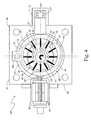
- Figure 4 shows a schematic representation in a cross section view of system components for use in the systems of Figures 2 and 3 .
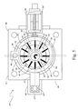
- Figure 5 shows a schematic representation in a cross section view of alternative system components for use in the systems of Figures 2 and 3 .
- Figure 6 shows a schematic representation in a cross section view of alternative system components for use in the systems of Figures 2 and 3 .
- Figure 7 shows a schematic representation in a cross section view of alternative system components for use in the systems of Figures 2 and 3 .
- Figure 8 shows a schematic representation in a cross section view of alternative system components for use in the systems of Figures 2 and 3 .
- electrohydraulic control systems for fuel pumps can be avoided in substantial degree by using a displacement adjustment motor of a suitable kind but instead under electromechanical system control.
- a displacement adjustment motor of a suitable kind but instead under electromechanical system control.
- Such an electromechanical controller selectively rotates a lead screw in one direction or the other to thereby move the changeable position displacement control element of the fluid, or fuel, pump being controlled.
- such an arrangement allows for determining if much of the system is in satisfactory operating condition without the need to pressurize the fuel.
- the displacement control element for the pump can be left in just the position it was in immediately before the failure to thereby maintain the same fuel flow assuming the pump rotor is being rotated from some other power source such as the engine being fueled by the pump.
- FIG. 2 shows a schematic block diagram of an arrangement for such a pump control system, 30, and a variable displacement vane pump, 31, controlled thereby with this pump appearing in more detail in the schematic representation of Figure 4 .
- Vane pump 31 has an inlet, 32, to which fuel is supplied, and has its rotor connected to a drive shaft, 33, to which torque for rotating that pump rotor is supplied by an external power source (not shown).
- shaft 33 can extend from the gearbox associated with a turbofan gas turbine engine (not shown).
- Vane pump 31 also has an outlet, 34, from which fuel pressurized by this pump is provided.
- FIG. 3 An alternative torque supply means for vane pump 31 is shown in the alternative arrangement, 30', in the schematic block diagram of Figure 3 in which shaft 33 is rotated by a locally provided electric motor, 35.
- This alternative arrangement thereby allows independent control of the pump rotor rotation rate rather than having it, if in an aircraft, as an example, merely follow the rotation rate established by the aircraft propulsion turbofan gas turbine engine during aircraft operations.
- the displacement adjustment motor for vane pump 31 in each of Figures 2 and 3 is a cam positioning motor arrangement, 36, to be used for changing the fluid volume displacement provided by that pump.
- Cam positioning motor arrangement 36 is shown in those figures to be under the control of an electronic controller, 37, which receives both commands to change thrust and various sensor inputs at its input, 38.
- Controller 37 may again be provided as part of the electronic engine controller (not shown), as is typical in an aircraft, or as an independent controller as shown, and may then be provided on or in the body of pump 31.
- Such an independent controller is typically provided as being capable of interacting with the electronic engine controller for the aircraft propulsion turbofan gas turbine engine if arrangement 30' is provided in an aircraft.
- torque supply electric motor 35 may be controlled by the electronic engine controller in this circumstance, or it may be controlled by independent controller 37, typically interacting with the electronic engine controller, or, possibly, by a further independent controller.
- Vane pump 31 has a pump body, 40, through which inlet 32 is provided to admit the working fluid to be pumped, and through which outlet 34 is provided for the pumped fluid to exit this pump.
- a rotor shaft, 33' extends through a bushing or a bearing in a rotation opening in pump body 40 to externally connect to drive shaft 33 of either of Figures 2 or 3 , is also affixed in a circular pump rotor, 41, to thereby be rotatable together about the axis of symmetry of rotor shaft 33' in the direction of the broad arrow shown within the rotor shaft outline.
- Rotor 41 has slot openings, 41', each provided therein extending parallel to a corresponding rotor radius and each is symmetrically positioned at every thirty degrees about the rotor center to thereby provide twelve of them in this example.
- Each of these slot openings opens at an outer end thereof to the outside of rotor 41 at the outer periphery thereof, and each opens into a spherical void at its interior end inside rotor 41.
- a corresponding vane, 42 Positioned in each of slot openings 41' is a corresponding vane, 42, which can move radially inward and outward in its slot opening along the radial axis therethrough.
- vanes 42 are forced outwardly against the interior surface of a circular opening, 43, in a circular cam ring, 44, to each significantly seal against that surface.
- Vanes 42 are so forced through use of fluid under pressure entering the spherical void of each slot opening to push the vane outward, or possibly just by use of the resulting centrifugal force on the vane due to the rotation thereof, or both.
- Rotor 41 within interior opening 43 of cam ring 44, and cam ring 44, are together positioned in an interior, circular cross section, accommodating space, or interior cavity, 45, in pump body 40.
- Cam ring 44 is pivotable about a pivot pin, 46, affixed through a pivot outward protuberance from the ring part thereof in the plane of that ring, and into pump body 40 which is shown offset horizontally in the figure from the axis of symmetry of rotor shaft 33'. This offset thereby leaves rotor 41 eccentrically mounted within interior opening 43 of cam ring 44.
- Such a mounting eccentricity leaves rotor 41 closer to the left side of the interior surface of circular opening 43 in cam ring 44 than it is to the right side of that interior surface.
- cam positioning motor arrangement 36 mounted on the exterior of pump body 40 using a flange
- Lead screw 36' of cain positioning motor arrangement 36 in being activated so as to force cam ring 44 maximally to the right in Figure 4 , provides the greatest offset between the center of cam ring 44 and the center of rotation of rotor 41 about the axis of symmetry of rotor shaft 33' to thereby yield the greatest pump volume displacement.
- a horizontal axis through lead screw 36' and the center of rotation of rotor 41 about the axis of symmetry of rotor shaft 33' is shown in dashed line form in Figure 4 .
- Two vertical axes, each perpendicular to this horizontal axis, are also shown in dashed line form in Figure 4 , one through the center of rotation of rotor 41 about the axis of symmetry of rotor shaft 33' and one through pivot pin 46 thereby showing the horizontal offset of these two locations.
- the horizontal axis through the center of rotation of rotor 41 intersecting lead screw 36' also extends from lead screw 36' through rotor 41 to a return force arrangement, 47, positioned about that axis on the opposite side of cam ring 44 from lead screw 36'.
- Lead screw 36' of cam positioning motor arrangement 36 in being activated to withdraw maximally to the left in Figure 4 , allows return force arrangement 47 to force cam ring 44 also to the left to provide the smallest offset (if an initial offset is provided as, otherwise, a zero offset could be reached) between the center of cam ring 44 and the center of rotation of rotor 41 about the axis of symmetry of rotor shaft 33' to thereby yield the smallest pump volume displacement.
- Cam positioning motor arrangement 36 is usually a suitable kind of linear actuator typically having a lead screw, such as lead screw 36', selectively forced to rotate in one direction or the other by an electric motor, 36", such as switched reluctance motor, a stepper motor or a permanent magnet motor as examples. Rotation of lead screw 36' causes it to move right or left in Figure 4 , depending on the direction of its rotation, through a threaded opening in the outer structure of motor 36" (serving as the "nut” within which the lead screw is turned).
- Control of the position of lead screw 36' can be implemented using a position measuring feedback sensor to provide a screw position signal to controller 37 rather than this controller just positioning the screw on an open loop basis.
- a feedback signal can be provided by using an arrangement to measure and transmit to controller 37 the occurrences of motor coil energizations and so the number of rotations of the motor output shaft, or some other manner of counting shaft rotations of the motor output shaft or the screw can be used.
- a flow sensor can be placed in the fuel line following pump 31 to provide a feedback signal to controller 37 for control purposes.
- motor 36" must be chosen to be capable of generating enough torque to rotate lead screw 36' so as to have that screw provide a linear force along its axis of longitudinal symmetry sufficient to overcome the return force provided by a return force arrangement, 47, mounted on the exterior of pump body 40.
- Return force arrangement 47 has a slidingly movable interface plug, 47', or piston, in contact with cam ring 44 through an opening in pump body 40, that is pushed by a spring, 47", which is initially partially compressed.
- This plug 47' and spring 47" together are provided in an open interior truncated cylindrical shell, or hollow cylinder, that is attached to the exterior of pump body 40 so as to be positioned about the corresponding opening therein used for admitting plug 47'.
- the spring constant of spring 47" essentially determines the amount of force provided by that spring at different spring length compressions, and so the return force applied by arrangement 47 to cam ring 44 at various positions thereof.
- fuel under pressure can be admitted the cylinder through an opening, 47"', behind plug 47' to push it against cam ring 44.
- the pressure of this fuel can be selected to an extent by connecting opening 47"' to a location ahead of pump inlet 32 or a location following pump outlet 34, or fuel under a pressure intermediate to these two pressures can be provided by mixing fuel quantities at these different pressures through an orifice system.
- the geometry of the threads of lead screw 36', and the threads in the cam positioning motor arrangement 36 that engage therewith serving as the nut about this screw, along with the effective friction coefficient between them, (and, or just, the fuel pressure in the cylinder) determine the amount of linear force that must be provided by return force arrangement 47 to force lead screw 36' through cam ring 44 to the left in Figure 4 in the absence of torque being supplied by motor 36".
- the choice of this thread geometry and the choice of the spring constant for spring 47" (and, or just, the fuel pressure in the cylinder) thus determines whether lead screw 36' will be moved to the left in the figure in the absence of torque being supplied by motor 36" such as following termination of operation of pump control system 30 and a variable displacement vane pump 31 by command or by some system failure.
- return force arrangement 47 cannot force lead screw 36' through cam ring 44 to the left in a system failure that leaves drive shaft 33 continuing to rotate pump rotor 41 at the same angular rate, such a failure will result in no change in the flow rate of fuel pumped by pump 31 to outlet 34 thereof. If, alternatively, return force arrangement 47 can force lead screw 36' to the left in a system failure that leaves drive shaft 33 continuing to rotate pump rotor 41 at the same angular rate, such a failure will nevertheless result in a significantly reduced rate of flow of fuel pumped by pump 31 to outlet 34 thereof as a result of the reduced pump displacement due to the forcing of lead screw 36' to the left.
- return force arrangement 47 can force lead screw 36' to the right in a system failure that leaves drive shaft 33 continuing to rotate pump rotor 41 at the same angular rate, such a failure will nevertheless result in a significantly increased rate of flow of fuel pumped by pump 31 to outlet 34 thereof as a result of the increased pump displacement due to the forcing of lead screw 36' to the right.
- Figure 6 shows, in a cross section view a schematic representation of a pump control system, 30 iv , a combined cam positioning motor and gearbox arrangement, 36"', having therein such a set of angular motion reducing gears, 36 iv .
- the teeth of the gear shown on the end of the motor output shaft drives a gear with more teeth formed on a rotatable gearbox "nut” structure rotatably supported on the motor and gearbox frames.
- Rotation of the gearbox "nut” structure motor 36" in one direction or the other again forces lead screw 36' to a corresponding right or left motion but at a smaller angular rate than that of the motor.
- the opposite result can be provided to give lead screw 36' a greater angular rate by reversing the gear teeth ratio of reducing gears 36 iv if instead desired.
- vane pump 31 The preciseness with which the flow rate of the fluid pumped by vane pump 31 is controlled can alternatively, or in addition, be provided by use of a fuel metering system of the kinds used previously with "fueldraulic" control systems described generally above. That is, a metering system following vane pump 31, having a metering valve under control of a regulator, can be operated to provide the desired rate of fuel flow at its outlet with the overflow fuel from the metering valve recirculated to pump 31 by the regulator after being received from the valve.
- Such a metering system could be provided following vane pump 31 in pump control system 30" of Figure 4 , thereby providing flow rate precision control in substituting in place of gears 36 iv and combined cam positioning motor and gearbox arrangement 36"' in pump control system 30 iv in Figure 6 .
- a metering system could be provided following vane pump 31 in pump control system 30 iv in Figure 6 to provide a finer resolution the control of the flow rate.
- cam ring 44 of Figures 4 , 5 and 6 are shown in cross section views of schematic representations of pump control systems in Figures 7 and 8 .
- a pump control system, 30 v is shown in Figure 7 with a modified cam ring, 44'.
- Modified cam ring 44' has a protuberance in the plane of the ring, or boss, 44", outward from the ring part thereof directly across from the pivot outward protuberance through which pivot pin 46 is affixed into pump body 40.
- Cam positioning motor arrangement 36 and return force arrangement 47 are repositioned in a modified pump body, 40', to be on opposite sides of boss 44" to each thereby be capable of rotating modified cam ring 44' as in pump control system 30" of Figure 4 .
- interchanging the positions of cam positioning motor arrangement 36 and return force arrangement 47 allows them to be capable of rotating modified cam ring 44' as in pump control system 30"' of Figure 5 .
- FIG. 8 A cross section view of a schematic representation of a pump control system, 30 vi , in Figure 8 shows that pivotable cam ring 44 of Figures 4 , 5 and 6 , and modified cam ring 44' of Figure 7 , can have substituted therefor a slidable cam ring, 44", provided in a suitably modified pump body, 40".
- Cam positioning motor arrangement 36 and return force arrangement 47 are again positioned in modified pump body 40" to be on opposite sides of slidable cam ring 44" to each thereby be capable of pushing to the right or the left, respectively, that ring to thereby alter the flow displacement in vane pump 31 as for cam rings 44 and modified cam ring 44'as in the previously described pump control systems of Figures 4 , 6 and 7 .
- cam positioning motor arrangement 36 and return force arrangement 47 allow them to be capable of pushing to the left or the right, respectively, slidable cam ring 44" to thereby alter the flow displacement in vane pump 31 as provided for cam ring 44 in the previously described pump control system of Figure 5 .
Landscapes
- Engineering & Computer Science (AREA)
- Mechanical Engineering (AREA)
- General Engineering & Computer Science (AREA)
- Rotary Pumps (AREA)
- Reciprocating Pumps (AREA)
- Details And Applications Of Rotary Liquid Pumps (AREA)
- Control Of Positive-Displacement Pumps (AREA)
Abstract
Description
- The present invention relates to control of the operation of rotary positive displacement fluid pumps and, more particularly, to control of the operation of variable flow rate rotary positive displacement fluid pumps.
- Rotary positive displacement fluid pumps are operated relatively simply by connecting the pump rotor to a source of mechanical torque, typically an electric motor or an engine, either directly or through some kind of a mechanical interconnection arrangement such as gears. The resulting rotation rate of the pump rotor determines the volume of the pump output fluid flow, and so a substantially constant engine rotation rate leads to a substantially constant pump output fluid flow rate. Such a pumping arrangement for providing fuel to gas turbine engines has been common in the past with the mechanical torque source having been a shaft extending to the pump rotor from the accessory gearbox of the gas turbine engine receiving the flow of fuel from the pump.
- However, gas turbine engines used in aircraft operate over a rather large range of engine rotation rates in rotating the gears in its accessory gearbox, and so often, at greater engine rotation rates, such engines cause the fuel supplied thereto by the corresponding fuel pump formed by a rotary positive displacement fluid pump to be in quantities that are substantially in excess of that needed to fuel operation of the engine. As a result, the excess fuel is typically recirculated back to a location in the fuel delivery system ahead of the fuel pump inlet. Such pressurizing of the fuel by the pump, and then the subsequent depressurizing thereof in returning that excess fuel to ahead of the pump inlet, more or less continually over a span of time causes the fuel to become significantly heated. The ensuing large fuel temperature increases have various detrimental effects with respect to operation of the turbine engine.
- Avoiding much of such heating has been accomplished by substituting variable flow rate control of rotary positive displacement fluid pumps in such a manner as make the pump output flow rate much less dependent on the rotation rate of the pump rotor, and so much less dependent on the rotation rates in the accessory gearbox of the gas turbine engines to which they are correspondingly supplying fuel. Typically, a vane pump is used as a rotary positive displacement fluid pump serving as the fuel pump in which the pump displacement can be varied, as well as the rotation rate of the pump rotor, to together determine the pump output flow rate. The variation of pump displacement can be achieved, for example, by changing the relative position of typically, a cam and the pump rotor within which that pump rotor is mounted off center to move cycloidally with respect thereto. Alternatively, a reciprocating piston pump with a variable position swash plate can be used to provide a variable rotation rate, variable displacement pump for a fuel pump. Relatively elaborate hydraulic pump control systems use the fuel as the "working fluid" in the control system, i.e. a "fueldraulics" control system, as well as that fluid being supplied by the pump and its control system to the corresponding gas turbine engine to be the engine fuel therefor.
- Such a pump displacement (and so pump output flow rate) control system and vane pump arrangement, 10, is shown in a schematic representation block diagram in
Figure 1 . A vane pump, 11, is shown with an inlet, 12, to which fuel is supplied through an inlet pressure source, 12', and the pump is also is connected to a shaft, 13, to which torque for rotating the pump rotor is supplied as a result of this shaft extending to the accessory gearbox of a gas turbine engine (not shown).Vane pump 11 has an outlet, 14, from which fuel pressurized by this pump is provided both to a pressured fluid conduit, 15, to a metering valve, 16, and an excess flow bypass conduit, 17. Valve 16, in cooperation with a regulator, 18, operates to provide the desired rate of fuel flow at its outlet, 19, to the gas turbine engine combustor (not shown) in compensating for the loss of fuel from the output ofvane pump 11 through pressuredfluid conduit 15. The overflow fuel is sent toregulator 18, through excess flow bypass conduit 17, and recirculated tovane pump 11 through a recirculation conduit, 20, carrying the fuel toinlet 12. The overflow amount is determined byregulator 18 determining the differential pressure acrossmetering valve 16 through a pair of differential pressure sensing conduits, 21. - The main control for the displacement of
pump 11 is provided typically as part of the engine electronic controller, 22, which receives both commands to change thrust and various sensor inputs at its input, 23.Controller 22 through an electrical interconnection, 24, operates an electrohydraulic servovalve, 25, with excess fluid therein returned tovane pump 11 through an excess fluid return conduit, 25', carrying the fuel torecirculation conduit 20.Electrohydraulic servovalve 25 in turn operates a hydraulic actuator, 26, through adding fluid thereto and removing fluid therefrom in control conduits, 27, to thereby force its output ram shaft, 28, to the left or right inFigure 1 . Such motion ofoutput ram shaft 28 thereby alters the position of the typical cycloidal motion cam invane pump 11 so as to either increase or decrease the fluid displacement of that pump. An output ram shaft position sensor, 29, provides a signal representing the linear position of that shaft as a feedback signal to controller 22. Thereby,controller 22 controls the fuel output flow rate of that pump throughoutlet 14 thereof. In addition, pressuredfluid conduit 15 allows the pressurized fuel output ofpump 11 to be supplied toelectrohydraulic servovalve 22 to provide steady quiescent flow as well as provide transient flow to actuate pump transients. - Such an elaborate electrohydraulic control system for vane pumps requires quite a number of component parts some of which are relatively expensive, plus requires quiescent flow and transient flows, affecting dynamic fuel response to the gas turbine engine, as well as pump sizing, and has limitations in failure modes such as in its ability to provide fixed fuel flow following a failure. In addition, various failure modes are introduced in such a complex system with so many system components, and the working fluid used therein is subject to contamination leading to further possible failure modes. Thus, there is a desire for a less complex control for controlling the displacement of vane pumps especially those used as fuel pumps for gas turbine engines.
- The present invention provides a variable displacement pump and pump control system therefor to pump a fluid at selected pump output flow rates in a range of pump output flow rates. The variable displacement pump has a rotor shaft with which to rotate a pump rotating member about an axis of rotation to force fluid that has entered a pump inlet to a pump outlet, and a fluid volume displacement selection controller to select a volume of fluid to be forced from the pump inlet to the pump outlet by the rotating member during a rotation thereof. A movable lead screw is coupled to the displacement selection controller so as to be capable of altering the position thereof as a result of selected motions of the lead screw, and a lead screw positioner is provided for selectively moving, or preventing the moving of, the movable lead screw by extending and retracting the lead screw through a threaded opening.
-
Figure 1 shows a schematic block diagram of a conventional pump control system and pump. -
Figure 2 shows a schematic block diagram of a pump control system and pump system embodying the present invention. -
Figure 3 shows a schematic block diagram of an alternative pump control system and pump system embodying the present invention. -
Figure 4 shows a schematic representation in a cross section view of system components for use in the systems ofFigures 2 and 3 . -
Figure 5 shows a schematic representation in a cross section view of alternative system components for use in the systems ofFigures 2 and 3 . -
Figure 6 shows a schematic representation in a cross section view of alternative system components for use in the systems ofFigures 2 and 3 . -
Figure 7 shows a schematic representation in a cross section view of alternative system components for use in the systems ofFigures 2 and 3 . -
Figure 8 shows a schematic representation in a cross section view of alternative system components for use in the systems ofFigures 2 and 3 . - The expense, weight and contamination risk, servo hydraulic losses due to quiescent operational flows, transient fuel sizing requirements, dynamic impacts of fuel transients, limited ability to fail so as to provide fuel at a fixed fuel flow rate, etc., of electrohydraulic control systems for fuel pumps can be avoided in substantial degree by using a displacement adjustment motor of a suitable kind but instead under electromechanical system control. Such an electromechanical controller selectively rotates a lead screw in one direction or the other to thereby move the changeable position displacement control element of the fluid, or fuel, pump being controlled. In addition, such an arrangement allows for determining if much of the system is in satisfactory operating condition without the need to pressurize the fuel. Further, in the event of a failure in the displacement adjustment motor such as because of an electric power outage, the displacement control element for the pump can be left in just the position it was in immediately before the failure to thereby maintain the same fuel flow assuming the pump rotor is being rotated from some other power source such as the engine being fueled by the pump.
-
Figure 2 shows a schematic block diagram of an arrangement for such a pump control system, 30, and a variable displacement vane pump, 31, controlled thereby with this pump appearing in more detail in the schematic representation ofFigure 4 .Vane pump 31 has an inlet, 32, to which fuel is supplied, and has its rotor connected to a drive shaft, 33, to which torque for rotating that pump rotor is supplied by an external power source (not shown). In an aircraft,shaft 33 can extend from the gearbox associated with a turbofan gas turbine engine (not shown). Vanepump 31 also has an outlet, 34, from which fuel pressurized by this pump is provided. An alternative torque supply means forvane pump 31 is shown in the alternative arrangement, 30', in the schematic block diagram ofFigure 3 in whichshaft 33 is rotated by a locally provided electric motor, 35. This alternative arrangement thereby allows independent control of the pump rotor rotation rate rather than having it, if in an aircraft, as an example, merely follow the rotation rate established by the aircraft propulsion turbofan gas turbine engine during aircraft operations. - The displacement adjustment motor for
vane pump 31 in each ofFigures 2 and 3 is a cam positioning motor arrangement, 36, to be used for changing the fluid volume displacement provided by that pump. Campositioning motor arrangement 36 is shown in those figures to be under the control of an electronic controller, 37, which receives both commands to change thrust and various sensor inputs at its input, 38.Controller 37 may again be provided as part of the electronic engine controller (not shown), as is typical in an aircraft, or as an independent controller as shown, and may then be provided on or in the body ofpump 31. Such an independent controller is typically provided as being capable of interacting with the electronic engine controller for the aircraft propulsion turbofan gas turbine engine if arrangement 30' is provided in an aircraft. Similarly, inFigure 3 , torque supplyelectric motor 35 may be controlled by the electronic engine controller in this circumstance, or it may be controlled byindependent controller 37, typically interacting with the electronic engine controller, or, possibly, by a further independent controller. - There is shown in the cross section view of
Figure 4 a schematic representation of a pump control system, 30", (omitting controller 37) withvane pump 31 and campositioning motor arrangement 36 ofFigures 2 and 3 .Vane pump 31 has a pump body, 40, through whichinlet 32 is provided to admit the working fluid to be pumped, and through whichoutlet 34 is provided for the pumped fluid to exit this pump. A rotor shaft, 33', extends through a bushing or a bearing in a rotation opening inpump body 40 to externally connect to driveshaft 33 of either ofFigures 2 or 3 , is also affixed in a circular pump rotor, 41, to thereby be rotatable together about the axis of symmetry of rotor shaft 33' in the direction of the broad arrow shown within the rotor shaft outline. -
Rotor 41 has slot openings, 41', each provided therein extending parallel to a corresponding rotor radius and each is symmetrically positioned at every thirty degrees about the rotor center to thereby provide twelve of them in this example. Each of these slot openings opens at an outer end thereof to the outside ofrotor 41 at the outer periphery thereof, and each opens into a spherical void at its interior end insiderotor 41. - Positioned in each of
slot openings 41' is a corresponding vane, 42, which can move radially inward and outward in its slot opening along the radial axis therethrough. During rotations ofrotor 41,vanes 42 are forced outwardly against the interior surface of a circular opening, 43, in a circular cam ring, 44, to each significantly seal against that surface.Vanes 42 are so forced through use of fluid under pressure entering the spherical void of each slot opening to push the vane outward, or possibly just by use of the resulting centrifugal force on the vane due to the rotation thereof, or both.Rotor 41 withininterior opening 43 ofcam ring 44, andcam ring 44, are together positioned in an interior, circular cross section, accommodating space, or interior cavity, 45, inpump body 40.Cam ring 44 is pivotable about a pivot pin, 46, affixed through a pivot outward protuberance from the ring part thereof in the plane of that ring, and intopump body 40 which is shown offset horizontally in the figure from the axis of symmetry of rotor shaft 33'. This offset thereby leavesrotor 41 eccentrically mounted withininterior opening 43 ofcam ring 44. Such a mounting eccentricity leavesrotor 41 closer to the left side of the interior surface ofcircular opening 43 incam ring 44 than it is to the right side of that interior surface. However, this relative closeness to, and remoteness from, the left and right sides of the interior surface ofinterior opening 43 ofcam ring 44 can be altered by the pivoting ofcam ring 44 about pivot pin 46 (and so an initial offset need not be provided as it can be supplied through this altering of closeness provided by pivoting of cam ring 44). - Such pivoting of
cam ring 44 aboutpivot pin 46 is forced by cam positioning motor arrangement 36 (mounted on the exterior ofpump body 40 using a flange) through selective positioning of a lead screw, 36', that is in contact withcam ring 44 through an opening inpump body 40. Lead screw 36' of cainpositioning motor arrangement 36, in being activated so as to forcecam ring 44 maximally to the right inFigure 4 , provides the greatest offset between the center ofcam ring 44 and the center of rotation ofrotor 41 about the axis of symmetry of rotor shaft 33' to thereby yield the greatest pump volume displacement. A horizontal axis through lead screw 36' and the center of rotation ofrotor 41 about the axis of symmetry of rotor shaft 33' is shown in dashed line form inFigure 4 . Two vertical axes, each perpendicular to this horizontal axis, are also shown in dashed line form inFigure 4 , one through the center of rotation ofrotor 41 about the axis of symmetry of rotor shaft 33' and one throughpivot pin 46 thereby showing the horizontal offset of these two locations. - The horizontal axis through the center of rotation of
rotor 41 intersecting lead screw 36' also extends from lead screw 36' throughrotor 41 to a return force arrangement, 47, positioned about that axis on the opposite side ofcam ring 44 from lead screw 36'. Lead screw 36' of campositioning motor arrangement 36, in being activated to withdraw maximally to the left inFigure 4 , allowsreturn force arrangement 47 to forcecam ring 44 also to the left to provide the smallest offset (if an initial offset is provided as, otherwise, a zero offset could be reached) between the center ofcam ring 44 and the center of rotation ofrotor 41 about the axis of symmetry of rotor shaft 33' to thereby yield the smallest pump volume displacement. - Cam
positioning motor arrangement 36 is usually a suitable kind of linear actuator typically having a lead screw, such as lead screw 36', selectively forced to rotate in one direction or the other by an electric motor, 36", such as switched reluctance motor, a stepper motor or a permanent magnet motor as examples. Rotation of lead screw 36' causes it to move right or left inFigure 4 , depending on the direction of its rotation, through a threaded opening in the outer structure ofmotor 36" (serving as the "nut" within which the lead screw is turned). - Control of the position of lead screw 36' can be implemented using a position measuring feedback sensor to provide a screw position signal to
controller 37 rather than this controller just positioning the screw on an open loop basis. Alternatively, such a feedback signal can be provided by using an arrangement to measure and transmit tocontroller 37 the occurrences of motor coil energizations and so the number of rotations of the motor output shaft, or some other manner of counting shaft rotations of the motor output shaft or the screw can be used. In another manner, a flow sensor can be placed in the fuelline following pump 31 to provide a feedback signal tocontroller 37 for control purposes. - Of course,
motor 36" must be chosen to be capable of generating enough torque to rotate lead screw 36' so as to have that screw provide a linear force along its axis of longitudinal symmetry sufficient to overcome the return force provided by a return force arrangement, 47, mounted on the exterior ofpump body 40.Return force arrangement 47 has a slidingly movable interface plug, 47', or piston, in contact withcam ring 44 through an opening inpump body 40, that is pushed by a spring, 47", which is initially partially compressed. This plug 47' andspring 47" together are provided in an open interior truncated cylindrical shell, or hollow cylinder, that is attached to the exterior ofpump body 40 so as to be positioned about the corresponding opening therein used for admitting plug 47'. The spring constant ofspring 47" essentially determines the amount of force provided by that spring at different spring length compressions, and so the return force applied byarrangement 47 tocam ring 44 at various positions thereof. In addition to, or instead of, use ofspring 47", fuel under pressure can be admitted the cylinder through an opening, 47"', behind plug 47' to push it againstcam ring 44. The pressure of this fuel can be selected to an extent by connectingopening 47"' to a location ahead ofpump inlet 32 or a location followingpump outlet 34, or fuel under a pressure intermediate to these two pressures can be provided by mixing fuel quantities at these different pressures through an orifice system. - The geometry of the threads of lead screw 36', and the threads in the cam
positioning motor arrangement 36 that engage therewith serving as the nut about this screw, along with the effective friction coefficient between them, (and, or just, the fuel pressure in the cylinder) determine the amount of linear force that must be provided byreturn force arrangement 47 to force lead screw 36' throughcam ring 44 to the left inFigure 4 in the absence of torque being supplied bymotor 36". The choice of this thread geometry and the choice of the spring constant forspring 47" (and, or just, the fuel pressure in the cylinder) thus determines whether lead screw 36' will be moved to the left in the figure in the absence of torque being supplied bymotor 36" such as following termination of operation ofpump control system 30 and a variabledisplacement vane pump 31 by command or by some system failure. - That is, if
return force arrangement 47 cannot force lead screw 36' throughcam ring 44 to the left in a system failure that leavesdrive shaft 33 continuing to rotatepump rotor 41 at the same angular rate, such a failure will result in no change in the flow rate of fuel pumped bypump 31 tooutlet 34 thereof. If, alternatively, returnforce arrangement 47 can force lead screw 36' to the left in a system failure that leavesdrive shaft 33 continuing to rotatepump rotor 41 at the same angular rate, such a failure will nevertheless result in a significantly reduced rate of flow of fuel pumped bypump 31 tooutlet 34 thereof as a result of the reduced pump displacement due to the forcing of lead screw 36' to the left. - The opposite result can be achieved by interchanging the positions shown in
Figure 4 of campositioning motor arrangement 36 and returnforce arrangement 47 ofFigures 2 and 3 with respect tocam ring 44. This arrangement is shown in a schematic representation of a pump control system, 30"', in the cross section view ofFigure 5 withvane pump 31 and the positionally interchangedcam positioning motor 36 and returnforce arrangement 47. Here, ifreturn force arrangement 47 cannot force lead screw 36' throughcam ring 44 to the right in a system failure that leavesdrive shaft 33 continuing to rotatepump rotor 41 at the same angular rate, such a failure again will result in no change in the flow rate of fuel pumped bypump 31 tooutlet 34 thereof. If, alternatively, returnforce arrangement 47 can force lead screw 36' to the right in a system failure that leavesdrive shaft 33 continuing to rotatepump rotor 41 at the same angular rate, such a failure will nevertheless result in a significantly increased rate of flow of fuel pumped bypump 31 tooutlet 34 thereof as a result of the increased pump displacement due to the forcing of lead screw 36' to the right. - The preciseness with which the flow rate of the fluid pumped by
vane pump 31 can be set by campositioning motor arrangement 36 in having lead screw 36' rotated bymotor 36" therein is determined inFigure 4 by the minimum movement to the right or left of that lead screw through a threaded opening in the motor frame serving as the "nut" through which the lead screw turns. This linear motion in one of two opposite directions occurs in response to that motor being directed to provide its smallest angular position increment of its output shaft in a corresponding rotation direction which, of course, is then also the smallest angular increment available to the lead screw forming that shaft. This smallest angular increment possible to be provided to its output shaft bymotor 36" can be converted to a significantly smaller angular increment for lead screw 36' by interposing a set of angular motion reducing gears between the motor output shaft and the lead screw. -
Figure 6 shows, in a cross section view a schematic representation of a pump control system, 30iv, a combined cam positioning motor and gearbox arrangement, 36"', having therein such a set of angular motion reducing gears, 36iv. The teeth of the gear shown on the end of the motor output shaft drives a gear with more teeth formed on a rotatable gearbox "nut" structure rotatably supported on the motor and gearbox frames. Rotation of the gearbox "nut"structure motor 36" in one direction or the other again forces lead screw 36' to a corresponding right or left motion but at a smaller angular rate than that of the motor. Of course, the opposite result can be provided to give lead screw 36' a greater angular rate by reversing the gear teeth ratio of reducinggears 36iv if instead desired. - The preciseness with which the flow rate of the fluid pumped by
vane pump 31 is controlled can alternatively, or in addition, be provided by use of a fuel metering system of the kinds used previously with "fueldraulic" control systems described generally above. That is, a metering system followingvane pump 31, having a metering valve under control of a regulator, can be operated to provide the desired rate of fuel flow at its outlet with the overflow fuel from the metering valve recirculated to pump 31 by the regulator after being received from the valve. Such a metering system could be provided followingvane pump 31 inpump control system 30" ofFigure 4 , thereby providing flow rate precision control in substituting in place ofgears 36iv and combined cam positioning motor andgearbox arrangement 36"' inpump control system 30iv inFigure 6 . Alternatively, such a metering system could be provided followingvane pump 31 inpump control system 30iv inFigure 6 to provide a finer resolution the control of the flow rate. - Alternatives for
cam ring 44 ofFigures 4 ,5 and6 are shown in cross section views of schematic representations of pump control systems inFigures 7 and8 . Rather than lead screw 36' being forced directly against the ring part ofcam ring 44 as inFigures 4 ,5 and6 , a pump control system, 30v, is shown inFigure 7 with a modified cam ring, 44'. Modified cam ring 44' has a protuberance in the plane of the ring, or boss, 44", outward from the ring part thereof directly across from the pivot outward protuberance through whichpivot pin 46 is affixed intopump body 40. Campositioning motor arrangement 36 and returnforce arrangement 47 are repositioned in a modified pump body, 40', to be on opposite sides ofboss 44" to each thereby be capable of rotating modified cam ring 44' as inpump control system 30" ofFigure 4 . Of course, interchanging the positions of campositioning motor arrangement 36 and returnforce arrangement 47 allows them to be capable of rotating modified cam ring 44' as inpump control system 30"' ofFigure 5 . - A cross section view of a schematic representation of a pump control system, 30vi, in
Figure 8 shows thatpivotable cam ring 44 ofFigures 4 ,5 and6 , and modified cam ring 44' ofFigure 7 , can have substituted therefor a slidable cam ring, 44", provided in a suitably modified pump body, 40". Campositioning motor arrangement 36 and returnforce arrangement 47 are again positioned in modifiedpump body 40" to be on opposite sides ofslidable cam ring 44" to each thereby be capable of pushing to the right or the left, respectively, that ring to thereby alter the flow displacement invane pump 31 as for cam rings 44 and modified cam ring 44'as in the previously described pump control systems ofFigures 4 ,6 and7 . Again, interchanging the positions of campositioning motor arrangement 36 and returnforce arrangement 47 allows them to be capable of pushing to the left or the right, respectively,slidable cam ring 44" to thereby alter the flow displacement invane pump 31 as provided forcam ring 44 in the previously described pump control system ofFigure 5 . - Although the present invention has been described with reference to preferred embodiments, workers skilled in the art will recognize that changes may be made in form and detail without departing from the scope of the invention, which is defined by the claims and their equivalents.
Claims (15)
- A variable displacement pump and pump control system (30) therefor to pump a fluid at selected pump output flow rates in a range of pump output flow rates, the system comprising:a variable displacement pump (31) having a rotor shaft (33) with which to rotate a pump rotating member about an axis of rotation to force fluid that has entered a pump inlet (32) to a pump outlet (34), and a fluid volume displacement selection controller (44) to select a volume of fluid to be forced from the pump inlet to the pump outlet by the rotating member during a rotation thereof,a movable lead screw (36') coupled to the displacement selection controller so as to be capable of altering the position thereof as a result of selected motion of the lead screw, anda lead screw positioner (36) for selectively moving, or preventing the moving of, the movable lead screw by extending and retracting the lead screw through a threaded opening.
- The system of claim 1 further comprising a position return force arrangement (47) coupled to the displacement selection controller (44) so as to be capable of tending to return the displacement selection controller to at least one position from which it was altered by motion of the lead screw (36').
- The system of claim 2 wherein the position return force arrangement (47) is capable of returning the displacement selection controller (44) to at least one position from which it was altered by motion of the lead screw (36') if the lead screw positioner is neither moving nor preventing the moving of the movable lead screw; or alternatively wherein the position return force arrangement (47) is incapable of returning the displacement selection controller (44) to at least one position from which it was altered by motion of the lead screw (36') if the lead screw positioner is neither moving nor preventing the moving of the movable lead screw
- The system of claim 2 or 3 wherein the returning by the position return force arrangement (47) of the displacement selection controller (44) to at least one position from which it was altered by motion of the lead screw increases the volume of fluid to be forced to the pump outlet by the rotating member during a rotation thereof; or alternatively wherein the returning by the position return force arrangement (47) of the displacement selection controller (44) to at least one position from which it was altered by motion of the lead screw decreases the volume of fluid to be forced to the pump outlet by the rotating member during a rotation thereof.
- The system of claim 1, 2, 3 or 4 wherein the lead screw positioner (36) comprises an electrically powered motor having an output shaft and an input terminal at which electrical power can be selectively supplied to correspondingly selectively cause the output shaft to rotate at a selected rotation rate.
- The system of claim 5 wherein the motor output shaft also comprises the lead screw (36')
- The system of claim 5 wherein the motor output shaft is coupled to the lead screw; preferably wherein the motor output shaft is coupled to the lead screw through a gear set (36iv).
- The system of claim 5, 6 or 7 wherein the electrically powered motor is a switched reluctance electric motor; or alternatively wherein the electrically powered motor is a stepper electric motor.
- The system of any preceding claim wherein the displacement selection controller (44) is a movable structure in the variable displacement pump (31) with movements thereof changing the volume of fluid forced to the pump outlet (34) by the rotating member (41) during a rotation thereof.
- The system of claim 9 wherein the variable displacement pump (31) is a vane pump.
- The system of claim 10 wherein the displacement selection controller in the vane pump comprises a movable cam ring (44) surrounding the pump rotating member (41) with a ring portion axis of symmetry substantially parallel to the axis of rotation but offset therefrom.
- The system of claim 11 wherein the cam ring (44) is pivotable about a pivot axis substantially parallel to the ring portion axis of symmetry but located adjacent to a part of the ring portion.
- The system of claim 11 wherein the cam ring (44") is slidable in a direction substantially perpendicular to the ring portion axis of symmetry.
- The system of any preceding claim further comprising an electric powered, variable speed pumping motor coupled to the rotor shaft.
- A variable displacement pump and pump control system therefor as claimed in any of claims 1 to 13 provided in an aircraft to pump a fuel to a gas turbine engine at selected pump output fuel flow rates in a range of pump output fuel flow rates, said rotor shaft being coupled to a gearbox coupled in turn to the gas turbine engine with which to rotate the pump rotating member.
Applications Claiming Priority (1)
| Application Number | Priority Date | Filing Date | Title |
|---|---|---|---|
| US12/215,248 US8128386B2 (en) | 2008-06-26 | 2008-06-26 | Variable flow pumping system |
Publications (2)
| Publication Number | Publication Date |
|---|---|
| EP2138718A2 true EP2138718A2 (en) | 2009-12-30 |
| EP2138718A3 EP2138718A3 (en) | 2013-08-14 |
Family
ID=40547929
Family Applications (1)
| Application Number | Title | Priority Date | Filing Date |
|---|---|---|---|
| EP09250571.8A Withdrawn EP2138718A3 (en) | 2008-06-26 | 2009-02-27 | Variable flow pumping system |
Country Status (2)
| Country | Link |
|---|---|
| US (1) | US8128386B2 (en) |
| EP (1) | EP2138718A3 (en) |
Cited By (2)
| Publication number | Priority date | Publication date | Assignee | Title |
|---|---|---|---|---|
| EP3382169A1 (en) * | 2017-03-27 | 2018-10-03 | Robert Bosch GmbH | Oil pump with electrically variable displacement |
| EP4123177A1 (en) * | 2021-07-23 | 2023-01-25 | Hamilton Sundstrand Corporation | Variable displacement pump systems with direct actuation |
Families Citing this family (19)
| Publication number | Priority date | Publication date | Assignee | Title |
|---|---|---|---|---|
| CA2679776A1 (en) * | 2008-10-08 | 2010-04-08 | Magna Powertrain Inc. | Direct control variable displacement vane pump |
| JP2012519253A (en) * | 2009-03-05 | 2012-08-23 | エスティティ テクノロジーズ インク.,ア ジョイントベンチャー オブ マグナ パワートレイン インク.アンド エスハーヴェー ゲーエムベーハー | Directly controlled linear variable displacement vane pump |
| JO3733B1 (en) | 2011-04-05 | 2021-01-31 | Bayer Ip Gmbh | Use of substituted 2,3-dihydroimidazo[1,2-c] quinazolines |
| US8736285B2 (en) | 2011-06-03 | 2014-05-27 | Hamilton Sundstrand Corporation | High temperature position sensor |
| US8794255B2 (en) * | 2011-08-25 | 2014-08-05 | Dennis Wayne Crabtree | Additive proportioning system |
| US9303638B2 (en) | 2012-06-25 | 2016-04-05 | Bell Helicopter Textron Inc. | Variable radial fluid devices in series |
| US9399984B2 (en) | 2012-06-25 | 2016-07-26 | Bell Helicopter Textron Inc. | Variable radial fluid device with counteracting cams |
| US9228571B2 (en) | 2012-06-25 | 2016-01-05 | Bell Helicopter Textron Inc. | Variable radial fluid device with differential piston control |
| US8776835B2 (en) | 2012-12-05 | 2014-07-15 | Hamilton Sundstrand Corporation | Fluid duct with improved connecting bead |
| JP6357355B2 (en) * | 2014-06-04 | 2018-07-11 | 株式会社日立製作所 | Radial piston pump |
| CN104196720B (en) * | 2014-07-07 | 2016-04-13 | 西安交通大学 | A kind of variable vane pump discharge capacity regulates uses AC servo machinery driving device |
| CN105507222A (en) * | 2015-11-20 | 2016-04-20 | 中国水利水电科学研究院 | Irrigation area canal system suitable for water culture of Tibetan region |
| CN105952831B (en) * | 2016-04-28 | 2018-01-23 | 北京化工大学 | A kind of eccentric adjusting vibration absorber for non-contact seals |
| DE102016209171A1 (en) * | 2016-05-25 | 2017-11-30 | Mahle International Gmbh | Pendulum slider machine, in particular oil pump, for an internal combustion engine of a motor vehicle |
| US10697453B2 (en) * | 2017-02-16 | 2020-06-30 | Liquid Controls Llc | Liquid fuel delivery comprising a pump to deliver liquid fuel from a storage source to a delivery location and a controller mitigating power to operate the pump on the basis of a predetermined liquid threshold at the pump inlet |
| US10753225B2 (en) * | 2017-03-31 | 2020-08-25 | The Boeing Company | Engine turning motor via pneumatic or hydraulic motor |
| US20180340501A1 (en) * | 2017-05-23 | 2018-11-29 | Weishun Willaim Ni | Variable displacement fuel pump with position sensor |
| CN113719333B (en) * | 2021-06-24 | 2023-08-22 | 东风汽车集团股份有限公司 | A variable displacement oil pump |
| US20240392780A1 (en) * | 2023-05-23 | 2024-11-28 | Hamilton Sundstrand Corporation | Variable displacement pump systems |
Family Cites Families (21)
| Publication number | Priority date | Publication date | Assignee | Title |
|---|---|---|---|---|
| GB489955A (en) * | 1937-02-05 | 1938-08-05 | Fluvario Ltd | Improvements in or relating to rotary engines |
| US2192660A (en) * | 1938-08-19 | 1940-03-05 | Pump Engineering Service Corp | Variable displacement fuel pump |
| US2821928A (en) * | 1954-11-15 | 1958-02-04 | Ernest E Wagner | Rotary device |
| GB839433A (en) * | 1958-01-14 | 1960-06-29 | Plenty And Son Ltd | Improvements in or relating to pump installations having two or more rotary pumps |
| US4325215A (en) * | 1977-03-10 | 1982-04-20 | Teijin Seiki Company Limited | Hydraulic apparatus |
| US4259039A (en) * | 1979-03-20 | 1981-03-31 | Integral Hydraulic & Co. | Adjustable volume vane-type pump |
| US4715180A (en) * | 1984-01-13 | 1987-12-29 | Dynamic Hydraulic Systems, Inc. | Hydraulic lift mechanism |
| US4770401A (en) * | 1986-09-08 | 1988-09-13 | Donaldson Humel J | Powered C-clamp apparatus |
| US5110100A (en) * | 1990-11-28 | 1992-05-05 | Robert Bosch Power Tool Corporation | Electric vise |
| US5538400A (en) | 1992-12-28 | 1996-07-23 | Jidosha Kiki Co., Ltd. | Variable displacement pump |
| US5715674A (en) | 1995-12-22 | 1998-02-10 | United Technologies Corporation | Hydromechanical control for a variable delivery, positive displacement fuel pump |
| US5806300A (en) | 1995-12-22 | 1998-09-15 | United Technologies Corporation | Electronic control for a variable delivery, positive displacement fuel pump |
| US6102001A (en) | 1998-12-04 | 2000-08-15 | Woodward Governor Company | Variable displacement pump fuel metering system and electrohydraulic servo-valve for controlling the same |
| GB9910074D0 (en) * | 1999-04-30 | 1999-06-30 | Lucas Ind Plc | Fuel control system and valve therefor |
| DE60010282T2 (en) | 1999-08-13 | 2005-05-19 | Argo-Tech Corp., Cleveland | Adjustable vane pump with adjustable shell halves |
| WO2002014693A1 (en) | 1999-08-13 | 2002-02-21 | Argo-Tech Corporation | Variable capacity pump for gas turbine engines |
| US6537047B2 (en) * | 2000-02-15 | 2003-03-25 | Frank H. Walker | Reversible variable displacement hydraulic pump and motor |
| US6623250B2 (en) | 2000-02-17 | 2003-09-23 | Goodrich Pump And Engine Control Systems, Inc. | Fuel metering unit |
| WO2002027188A2 (en) * | 2000-09-28 | 2002-04-04 | Goodrich Pump & Engine Control Systems, Inc. | Vane pump |
| WO2002061922A1 (en) * | 2001-01-26 | 2002-08-08 | Tol-O-Matic, Inc. | Electric actuator for rotary and linear motion |
| US7293765B2 (en) * | 2005-07-07 | 2007-11-13 | Hooper Ronald L | Power vise |
-
2008
- 2008-06-26 US US12/215,248 patent/US8128386B2/en active Active
-
2009
- 2009-02-27 EP EP09250571.8A patent/EP2138718A3/en not_active Withdrawn
Cited By (2)
| Publication number | Priority date | Publication date | Assignee | Title |
|---|---|---|---|---|
| EP3382169A1 (en) * | 2017-03-27 | 2018-10-03 | Robert Bosch GmbH | Oil pump with electrically variable displacement |
| EP4123177A1 (en) * | 2021-07-23 | 2023-01-25 | Hamilton Sundstrand Corporation | Variable displacement pump systems with direct actuation |
Also Published As
| Publication number | Publication date |
|---|---|
| US8128386B2 (en) | 2012-03-06 |
| US20090324438A1 (en) | 2009-12-31 |
| EP2138718A3 (en) | 2013-08-14 |
Similar Documents
| Publication | Publication Date | Title |
|---|---|---|
| US8128386B2 (en) | Variable flow pumping system | |
| US20220025910A1 (en) | Self-contained energy efficient hydraulic actuator system | |
| EP3406903B1 (en) | Variable displacement fuel pump with position sensor | |
| US6116139A (en) | Pneumatically powered linear actuator control apparatus and method | |
| EP2414680B1 (en) | High pressure variable displacement piston pump | |
| JP2010532040A (en) | Self-contained hydraulic actuator system | |
| US20180230870A1 (en) | Engine oil pump with electronic oil pressure control | |
| CN114791001A (en) | Digital pump control valve and method for variable control of hydraulic pump | |
| CN112377382B (en) | Variable axial plunger pump based on proportional pressure reducing valve control | |
| US7249458B2 (en) | Self-contained hydraulic actuator system | |
| WO2000016464A9 (en) | Control system with integrated actuation package | |
| CN100491772C (en) | Manual servo-controlled double-variable hydraulic transmission device | |
| US5378112A (en) | Positive displacement, variable delivery pumping apparatus | |
| JP7760371B2 (en) | Hydraulic actuator with overpressure compensation | |
| JPH0960604A (en) | Hydraulic converter and hydraulic control circuit | |
| CN116025608B (en) | A servo valve with external zero-adjustment structure | |
| JPH10281056A (en) | High pressure pump | |
| JPH0742663A (en) | Windmill | |
| CN116717509B (en) | A miniature electro-hydraulic actuator | |
| CN121611797A (en) | Integrated digital hydraulic driving device | |
| RU2029890C1 (en) | Electrohydraulic servo drive | |
| CN117703850A (en) | Hydraulic motor system and control method thereof | |
| CN117738865A (en) | Variable displacement pump system and control method thereof | |
| JPH0552267U (en) | Controller for variable displacement rotary machine | |
| HK1241955A1 (en) | Self-contained energy efficient hydraulic actuator system |
Legal Events
| Date | Code | Title | Description |
|---|---|---|---|
| PUAI | Public reference made under article 153(3) epc to a published international application that has entered the european phase |
Free format text: ORIGINAL CODE: 0009012 |
|
| AK | Designated contracting states |
Kind code of ref document: A2 Designated state(s): AT BE BG CH CY CZ DE DK EE ES FI FR GB GR HR HU IE IS IT LI LT LU LV MC MK MT NL NO PL PT RO SE SI SK TR |
|
| AX | Request for extension of the european patent |
Extension state: AL BA RS |
|
| PUAL | Search report despatched |
Free format text: ORIGINAL CODE: 0009013 |
|
| AK | Designated contracting states |
Kind code of ref document: A3 Designated state(s): AT BE BG CH CY CZ DE DK EE ES FI FR GB GR HR HU IE IS IT LI LT LU LV MC MK MT NL NO PL PT RO SE SI SK TR |
|
| AX | Request for extension of the european patent |
Extension state: AL BA RS |
|
| RIC1 | Information provided on ipc code assigned before grant |
Ipc: F04B 1/07 20060101AFI20130710BHEP Ipc: F04C 14/22 20060101ALI20130710BHEP |
|
| AKY | No designation fees paid | ||
| REG | Reference to a national code |
Ref country code: DE Ref legal event code: R108 |
|
| REG | Reference to a national code |
Ref country code: DE Ref legal event code: R108 Effective date: 20140423 |
|
| STAA | Information on the status of an ep patent application or granted ep patent |
Free format text: STATUS: THE APPLICATION IS DEEMED TO BE WITHDRAWN |
|
| 18D | Application deemed to be withdrawn |
Effective date: 20140215 |