EP2138675A2 - A rotor blade - Google Patents
A rotor blade Download PDFInfo
- Publication number
- EP2138675A2 EP2138675A2 EP09251535A EP09251535A EP2138675A2 EP 2138675 A2 EP2138675 A2 EP 2138675A2 EP 09251535 A EP09251535 A EP 09251535A EP 09251535 A EP09251535 A EP 09251535A EP 2138675 A2 EP2138675 A2 EP 2138675A2
- Authority
- EP
- European Patent Office
- Prior art keywords
- aerofoil
- apertures
- plane
- entry
- coolant
- Prior art date
- Legal status (The legal status is an assumption and is not a legal conclusion. Google has not performed a legal analysis and makes no representation as to the accuracy of the status listed.)
- Withdrawn
Links
- 239000002826 coolant Substances 0.000 claims abstract description 50
- 238000001816 cooling Methods 0.000 abstract description 53
- 239000012530 fluid Substances 0.000 abstract description 31
- 230000000694 effects Effects 0.000 abstract description 20
- 230000003068 static effect Effects 0.000 abstract description 13
- 230000037406 food intake Effects 0.000 abstract description 3
- 239000000463 material Substances 0.000 abstract description 3
- 238000007493 shaping process Methods 0.000 description 11
- 230000008901 benefit Effects 0.000 description 4
- 239000000446 fuel Substances 0.000 description 3
- 230000001141 propulsive effect Effects 0.000 description 3
- 230000009467 reduction Effects 0.000 description 3
- 230000009286 beneficial effect Effects 0.000 description 2
- 239000012141 concentrate Substances 0.000 description 2
- 230000007423 decrease Effects 0.000 description 2
- 238000000034 method Methods 0.000 description 2
- 230000001133 acceleration Effects 0.000 description 1
- 239000000654 additive Substances 0.000 description 1
- 230000000996 additive effect Effects 0.000 description 1
- 230000002411 adverse Effects 0.000 description 1
- 230000004075 alteration Effects 0.000 description 1
- 230000015572 biosynthetic process Effects 0.000 description 1
- 230000008859 change Effects 0.000 description 1
- 238000002485 combustion reaction Methods 0.000 description 1
- 230000006835 compression Effects 0.000 description 1
- 238000007906 compression Methods 0.000 description 1
- 230000001419 dependent effect Effects 0.000 description 1
- 230000006872 improvement Effects 0.000 description 1
- 238000002844 melting Methods 0.000 description 1
- 230000008018 melting Effects 0.000 description 1
- 239000000203 mixture Substances 0.000 description 1
- 238000012986 modification Methods 0.000 description 1
- 230000004048 modification Effects 0.000 description 1
- 239000003921 oil Substances 0.000 description 1
- 230000001151 other effect Effects 0.000 description 1
- 230000008569 process Effects 0.000 description 1
- 238000000926 separation method Methods 0.000 description 1
- XLYOFNOQVPJJNP-UHFFFAOYSA-N water Substances O XLYOFNOQVPJJNP-UHFFFAOYSA-N 0.000 description 1
- 230000003313 weakening effect Effects 0.000 description 1
Images

Classifications
-
- F—MECHANICAL ENGINEERING; LIGHTING; HEATING; WEAPONS; BLASTING
- F01—MACHINES OR ENGINES IN GENERAL; ENGINE PLANTS IN GENERAL; STEAM ENGINES
- F01D—NON-POSITIVE DISPLACEMENT MACHINES OR ENGINES, e.g. STEAM TURBINES
- F01D5/00—Blades; Blade-carrying members; Heating, heat-insulating, cooling or antivibration means on the blades or the members
- F01D5/12—Blades
- F01D5/14—Form or construction
- F01D5/18—Hollow blades, i.e. blades with cooling or heating channels or cavities; Heating, heat-insulating or cooling means on blades
- F01D5/187—Convection cooling
-
- F—MECHANICAL ENGINEERING; LIGHTING; HEATING; WEAPONS; BLASTING
- F05—INDEXING SCHEMES RELATING TO ENGINES OR PUMPS IN VARIOUS SUBCLASSES OF CLASSES F01-F04
- F05D—INDEXING SCHEME FOR ASPECTS RELATING TO NON-POSITIVE-DISPLACEMENT MACHINES OR ENGINES, GAS-TURBINES OR JET-PROPULSION PLANTS
- F05D2240/00—Components
- F05D2240/10—Stators
- F05D2240/12—Fluid guiding means, e.g. vanes
- F05D2240/121—Fluid guiding means, e.g. vanes related to the leading edge of a stator vane
-
- F—MECHANICAL ENGINEERING; LIGHTING; HEATING; WEAPONS; BLASTING
- F05—INDEXING SCHEMES RELATING TO ENGINES OR PUMPS IN VARIOUS SUBCLASSES OF CLASSES F01-F04
- F05D—INDEXING SCHEME FOR ASPECTS RELATING TO NON-POSITIVE-DISPLACEMENT MACHINES OR ENGINES, GAS-TURBINES OR JET-PROPULSION PLANTS
- F05D2240/00—Components
- F05D2240/20—Rotors
- F05D2240/30—Characteristics of rotor blades, i.e. of any element transforming dynamic fluid energy to or from rotational energy and being attached to a rotor
- F05D2240/303—Characteristics of rotor blades, i.e. of any element transforming dynamic fluid energy to or from rotational energy and being attached to a rotor related to the leading edge of a rotor blade
-
- F—MECHANICAL ENGINEERING; LIGHTING; HEATING; WEAPONS; BLASTING
- F05—INDEXING SCHEMES RELATING TO ENGINES OR PUMPS IN VARIOUS SUBCLASSES OF CLASSES F01-F04
- F05D—INDEXING SCHEME FOR ASPECTS RELATING TO NON-POSITIVE-DISPLACEMENT MACHINES OR ENGINES, GAS-TURBINES OR JET-PROPULSION PLANTS
- F05D2260/00—Function
- F05D2260/20—Heat transfer, e.g. cooling
- F05D2260/201—Heat transfer, e.g. cooling by impingement of a fluid
Definitions
- the present invention relates to rotor blades and more particularly to turbine rotor blades utilised in gas turbine engines.
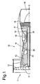
- a gas turbine engine is generally indicated at 10 and comprises, in axial flow series, an air intake 11, a propulsive fan 12, an intermediate pressure compressor 13, a high pressure compressor 14, a combustor 15, a turbine arrangement comprising a high pressure turbine 16, an intermediate pressure turbine 17 and a low pressure turbine 18, and an exhaust nozzle 19.
- the gas turbine engine 10 operates in a conventional manner so that air entering the intake 11 is accelerated by the fan 12 which produce two air flows: a first air flow into the intermediate pressure compressor 13 and a second air flow which provides propulsive thrust.
- the intermediate pressure compressor compresses the air flow directed into it before delivering that air to the high pressure compressor 14 where further compression takes place.
- the compressed air exhausted from the high pressure compressor 14 is directed into the combustor 15 where it is mixed with fuel and the mixture combusted.
- the resultant hot combustion products then expand through, and thereby drive, the high, intermediate and low pressure turbines 16, 17 and 18 before being exhausted through the nozzle 19 to provide additional propulsive thrust.
- the high, intermediate and low pressure turbines 16, 17 and 18 respectively drive the high and intermediate pressure compressors 14 and 13 and the fan 12 by suitable interconnecting shafts 26, 28, 30.
- blades and vanes are cooled using high pressure coolant air taken from the compressor stages which has bypassed the combustor and is therefore relatively cool compared to the engine.
- the coolant air temperature will be in the order of 700 to 1,000 K whilst the gas temperature in the high pressure turbine stage will be in excess of 2,100 K.
- Coolant air taken from the compressor in order to cool the turbine results in a reduction in engine operating efficiency. It will be appreciated that the coolant air extracted does not produce thrust and in such circumstances has an adverse effect. In the above circumstances it will be appreciated that it is important that the amount of cooling air is minimised and it is used as effectively as possible.
- Impingement cooling can produce high levels of internal heat transfer for cooling of the aerofoil. Furthermore, cooling is improved by sufficiently high pressure ratios across the impingement holes of the cooling arrangement. However, increasing pressure ratio may be difficult as impingement gas pressure cannot be varied due to a requirement for a minimum pressure to prevent hot gas ingestion into the coolant chamber. Similarly, increasing the feed pressure for cooling will be less efficient due to increased leakage of coolant.
- Recent impingement cooling systems have involved orientating generally cylindrical shaped impingement jets through an angle of approximately 30° to 40° to the perpendicular. This change in geometry has the effect of improving the entrance loss and allowing the feed pressure to increase from the static flow pressure to a higher pressure comprising the static pressure plus a proportion of the dynamic pressure due to local velocity of the flow in the feed passage. In such circumstances the pressure ratio across the impingement jets can be increased without changing the incident static blade feed pressure taken from the by-pass.
- alternative configurations may include provision of pedestals or pin fins in the feed passage to direct cooling flow it will be understood these features will also partially obstruct flow and therefore act as deflectors to the flow. Furthermore aligning the direction of the deflected flow to the apertures or orifices for impingement direction can be difficult and may result in entrance losses to the apertures.
- the present invention provides an aerofoil for a gas turbine engine
- the aerofoil comprises a passage partly defined by a divider wall, along which coolant flows, and a chamber defined partly by the divider wall and a chamber wall, a plurality of feed apertures is defined in the divider wall to supply the coolant to impinge on the chamber wall, the feed apertures comprise a centre-line, an entry plane and an exit plane, the aerofoil is characterised in that at least one of the feed apertures comprises a centre-line that is non-linear, in a plane parallel to the coolant flow, between the entry plane and the exit plane.
- the divider wall comprises a thickened part through which the feed apertures are defined.
- the centre-line at the entry plane may be angled ⁇ up to 90 degrees from the coolant flow direction.
- the centre-line at the entry plane is angled ⁇ between 30 and 60 degrees from the coolant flow direction and in an exemplary embodiment the centre-line at the entry plane is angled ⁇ at approximately 45 degrees from the coolant flow direction.
- the plurality of apertures are comprises apertures having different angles ⁇ to preferentially vary the amount of coolant channelled through the apertures.
- the centre-line at the exit plane is angled ⁇ up to 30 degrees to the surface of the chamber wall.
- the centre-line at the exit plane is angled ⁇ at 90 +/- 10 degrees to the surface of the chamber wall.
- the plurality of apertures are comprises apertures having different angles ⁇ to preferentially vary the direction of coolant impinging on the chamber wall.
- At least one aperture comprises a convergent part between the entry plane and the exit plane.
- At least one aperture comprises a divergent part between the entry plane and the exit plane.
- At least one aperture comprises a greater entry plane area than the exit plane area.
- the plurality of apertures comprises apertures having different entry plane areas to preferentially direct different amounts of coolant therethrough.
- At least one aperture comprises an elliptical entry plane.
- At least one aperture comprises an elliptical or circular exit plane.
- an aerofoil for a gas turbine engine including a passage having a plurality of feed apertures to a cooling cavity, the aerofoil associated with means to stimulate fluid flow in the passage, the aerofoil characterised in that at least some of the feed apertures have an elliptical entry and a shaped exit, the elliptical entry orientated to gather the fluid flow and the exit orientated to eject the fluid flow through the feed aperture towards an opposed portion of the cooling chamber at a desired angle.
- the means to stimulate fluid flow is at least in part static pressure in the fluid.
- the desired angle is perpendicular.
- the shaped exit is circular.
- the shaped exit is elliptical. Possibly the shaped exit provides a wider cross sectional area than the entry. Alternatively, the elliptical exit is narrower than the entry.
- the cavity includes edge apertures.
- the feed apertures are shaped between the entry and the exit for fluid flow ejection.
- the passage incorporates deflectors to deflect the fluid flow towards the entry.
- the fluid flow is ejected by the feed aperture perpendicular to the opposed portion of the cavity.
- the apertures are all substantially of the same size.
- the apertures have different sizes dependent upon their position within the aerofoil.
- a plurality of apertures is provided in a regular pattern in a divider wall between the passage and the cooling cavity.
- radial refers to the rotational axis of the engine shown in Figure 1 .
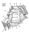
- FIG. 2 provides a part perspective view of a turbine section of a gas turbine engine.
- an aerofoil 30 is secured between an inner platform 31 and an outer platform 32.
- the aerofoil 30 acts as a nozzle guide vane directing and guiding a hot gas flow in co-operation with other aerofoils as nozzle guide vanes towards rotor blades 33 themselves formed as aerofoils.
- the rotor blades 33 are assembled upon a rotor mounting through a root fixing 29 and are arranged to rotate in use. It will be noted that the rotor blades 33 include a platform 34 at one end and a wing portion 35 at the other to act in association with a seal shroud 36.
- the whole arrangement is supported on a suitable support structure such as a turbine support casing 37.
- the aerofoils 30, 33 defining the nozzle guide vanes and rotor blades in accordance with aspects of the present invention incorporate apertures 38, 39 about their surface in order to define in use film cooling upon those surfaces.
- the coolant flows within the aerofoils 30, 33 typically through multi-pass processes cool the aerofoils 30, 33 as components before presentation of the film cooling after ejection through the apertures 38, 39. It is obtaining best effective use of the coolant flows, particularly with regard to the aerofoils 30, 33, which is of particular concern with respect to aspects of the present invention.
- aspects of the present invention attempt to combine the benefits of focused presentation of a coolant flow to a portion of a surface to be cooled whilst achieving enhanced feed pressure for the fluid flow.
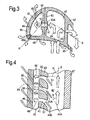
- Figure 3 provides a schematic part cross section of a leading edge region of an aerofoil in accordance with the present invention.
- a radial passage 40 provides a fluid flow in the form of a coolant to a series of shaped orifices or feed apertures 41 in a divider wall 43 between the passage 40 and a cooling chamber or cavity 42.
- the divider wall 43 has been locally thickened 43A to accommodate and enhance the effectiveness of the apertures 41. As will be described later this thickened wall 43A will allow formation of specific shaping for each feed aperture 41.
- fluid flow in the form of coolant 44 will pass radially outwardly along the radial passage 40 and as indicated exit through the feed aperture 41 as well as surface apertures 45 and edge apertures 46.
- the coolant or fluid flow 44 will provide internal cooling within the aerofoil 47 as well as film cooling on the surface of the aerofoil 47 through coolant ejected through the apertures 45, 46.
- a fluid flow 48, derived from coolant flow 44, through the feed aperture 41 is directed to impinge substantially at a perpendicular angle with an opposed wall portion 95 partly forming the chamber 42.
- FIG 4 shows a section A-A as depicted in figure 3 , that is to say a sectional view through an aperture 41 depicted and leading edge aperture 46a.
- the feed fluid flow 44 passes through in the direction of arrowheads 44a with a feed pressure comprising the static pressure of the flow.
- the feed apertures 41 are shaped such that an entry part 51 is generally elliptical whilst an exit part 52 is generally circular.
- a proportion of the feed fluid flow 44b is gathered by the elliptical entrance portion 51 and passes through the feed aperture 41 and out of the exit part 52 such that it is projected substantially perpendicularly to respective wall portions of the chamber 42. With such perpendicular impingement more focussed heat transfer cooling occurs and subsequently the fluid flow as coolant passes through the edge apertures 46 in order to create a film cooling effect 54.
- the aperture(s) comprises an entry plane 51A and an exit plane 52A; the area of the entry plane is greater than the area of the exit plane 52A.
- the aperture (s) 41 has a centre-line 41A that is angled ⁇ at to the coolant flow, which in this example, is in the radial direction; the centre-line is curved in the plane shown in Figure 4 . As shown in this embodiment, the angle ⁇ is approximately 45°, but any angle would be beneficial although between 30° and 60° is most preferably.
- the centre-line passing through the exit has an angle ⁇ which is preferably approximately 90° (+/-10°) to the surface of the wall 95, although angles up to 30° to the surface would be beneficial.
- the centre-line in this and the other embodiments, is a line that intersects a geometric centre of area at any cross-section.
- the invention relates to at least one of the feed apertures comprising a centre-line that is non-linear in a plane parallel to the coolant flow, which is usually in a radial direction with respect to an aerofoil, between the entry plane and the exit plane.
- This parallel plane is that defined by the sections shown in the exemplary figures 4 , 6 and 8 .
- the ejected impingement jets 48 can be maximised to ensure that a dynamic pressure component is additive to the static pressure component.
- An enhanced feed pressure is achieved with the impingement configuration as depicted in figure 3 and figure 4 , which enhances and maximises feed pressure by choice of the appropriate inlet angle through the elliptical entry portion 51.
- an impingement jet 48 is created which strikes the wall at a desired angle which is typically perpendicular in order to concentrate heat transfer over a focused area of the opposed portion of a chamber 42 surface subject to impingement by the impingement jets 48.
- the angle ⁇ may be adapted which alters the entry plane area 51A shape at the elliptical entry portion 51 may be varied along the length of the aerofoil 47 in order to preferentially cool parts of the wall 95.
- elliptical shaping of the entry portions 51 may be tailored to channel the feed fluid flow 44 whilst other portions may be tailored to have a reduced effectiveness with respect to ingestion of the coolant feed flow 44 at root and tip portions of the aerofoil 47.
- angle ⁇ of the centre-line 41A of the aperture 41 at the inlet plane is greater where more coolant is desired, in this case, adjacent to the mid-height region of the aerofoil than near the tip or root regions. With a greater angle ⁇ more coolant is drawn into the aperture.
- the degree of convergence and constriction provided between the entry portion 51 and the shaped exit portion 52 can be adjusted at different locations along the aerofoil 47 to provide greater or lesser presentation of the impingement jet flows 48 for differing cooling effect.
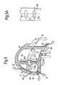
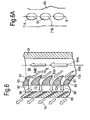
- Figure 5 and figure 6 provide illustrations of a second embodiment of the present invention in which the entry portion is again elliptical in shape whilst the exit portion has an elliptical shape diverging between the entry portion and the exit portion.
- Figure 5 provides a schematic part cross section of a leading edge portion of an aerofoil 67.
- a passage 60 receives a fluid flow 64 which is projected radially and enters feed apertures 61 for projection and presentation into a chamber or cavity 62 towards an opposed portion of the wall 95 of the cavity.
- the fluid flow is typically a coolant flow and therefore provides a cooling effect within the chamber 62 and the wall 95 before egress through apertures 66 to define the coolant film on the aerofoil 67 external surface.
- a dividing wall 63 is provided between the passage 60 and the chamber 62.
- the dividing wall 63 comprises a locally thickened part 63A in order to allow earlier provision of the feed aperture 61.
- the thickened part 63A allows a longer aperture 41 and one that is sufficient to turn the coolant flow as described herein.
- the fluid flow 64 provides a cooling effect within the chamber 62 initially and then upon the egress from the edge apertures 66 creates film cooling 68 about the aerofoil 67.
- the second embodiment depicted in figure 5 and figure 6 differs from the first embodiment with regard to the shaping of the feed apertures 61.
- the apertures 61 comprise an entry portion 71 having an entry plane 71A, an exit portion 72 having an exit plane 72A and a centre-line 61A.
- the entry plane 71A is elliptical having a major axis 71B ( Figure 6A ) aligned with the direction of flow 64a which is itself aligned with a radial line 9 with respect to the aerofoil, that is to say the root to tip.
- part of the fluid flow 64a is channelled through the shaping of the entry plane 71A and accelerated and turned within the feed aperture 61, along the curved centre-line 61A having an angle ⁇ at the entry plane, in a manner such that it emerges through the exit portion 72. Such emergence is again substantially perpendicular towards an opposed wall portion of the chamber 62.
- Figure 5A is a view on arrow D in Figure 5 and shows the aperture's exit plane 72A, which is an elliptical shape.
- a major axis 72B of the elliptical exit plane 72A is approximately perpendicular to the radial line 9.
- Figure 6A is a view on arrow E in Figure 6 and shows the aperture's entry plane 71A, which is an elliptical shape.
- a major axis 71B of the entry plane is approximately parallel to the radial line 9, and more importantly the direction of the flow 64a.
- the major axes 71B, 72B may vary by up to 45° while still being useful.
- the impingement footprint of the impingement flow 68 is elliptical in shape with its minor axis aligned in the radial direction with respect of the blade geometry, that is to say root to tip.
- the configuration as depicted in figure 5 and figure 6 is better suited to nozzle guide vane aerofoils due to the fact that the elliptical shape of the impingement jet 68 exits would increase stress concentration in a rotor blade application due to centrifugal loading. Nevertheless, the spread of the impingement jet 68 from each feed aperture 61 in the aerofoil 67 will improve cooling effects in a static nozzle guide vane aerofoil cooling arrangement.
- an inner surface of the chamber 62 is curved (see Figure 5 , wall 95).
- the direction of the impingement jets or flow 68 may be rendered still more perpendicular to the opposed surface of the chamber 62.
- the area of the entry plane is preferably greater than the exit plane area of the aperture (41, 61, 81) and therefore coolant flow through the aperture is accelerated from entry to exit to improve its impingement cooling effect on wall 95. It should be noted that the degree of convergence in Figure 6 of aperture 61 is greater than its divergence in the orthogonal plane (viz Figure 6 and Figure 5 ).
- the aperture(s) (41, 61, 81) may be convergent-divergent having a greater exit plane area than entry plane area. This may be where a greater area of the wall 95 requires impingement cooling for example.
- Figures 7 and 8 provide an illustration of a third embodiment of an aerofoil in accordance with aspects of the present invention.
- Figure 7 provides a schematic part section of a leading edge of an aerofoil 87.
- the third embodiment provides for an arrangement which is more suitable to, but not exclusively, rotor blade aerofoils.
- Figure 8 provides a section at a plane C-C through an aperture 81 in a separation wall 83 between a radial passage 80 and a chamber 82 in the aerofoil 87 depicted in figure 7 .
- the convergent and curved aperture comprises an entry portion 91 having an elliptical or possibly a circular entry plane 91A and an exit plane that is also elliptical.
- the aperture 81 accelerates and turns a fluid flow 84b in a similar manner to previous embodiments.
- the exit plane shape 92B is elliptical in shape with its major axis aligned with the flow 94b and in this example a radial line 9.
- An emerging impingement flow 88 strikes an inner opposed surface of the wall 95 of the chamber 82 at an approximately perpendicular angle. This concentrates the flow 88 improving its effectiveness to cover a wider area defined by an elliptical impingement footprint.
- the impingement jets 48, 68, 88 are directed at parts of the wall 95 comprising no apertures 46, 66, 86.
- the apertures 46, 66, 86 may be desirable to increase coolant flow therethrough or to enhance cooling around these impingement apertures.
- apertures in accordance with the present invention include an elliptical entry portion which bends through the passage and effectively turns the cooling or fluid flow for impingement as required.
- impingement jets can be orientated to strike desired locations within a cavity or chamber such as at a suction surface, pressure surface or be directed towards a stagnation point in the aerofoil where greater cooling is required.
- the apertures may be shaped differently internally possibly having a constant cross sectional area, contact area or a convergent/divergent route between the entry portion and the exit portion to achieve better projection of the impingement flow to an opposed portion of the chamber surface.
- additional extended surfaces such as fins, pin fins or tyre tracks etc may be added to the aperture to increase the wetted area of both the aperture and the opposed surface to which the impingement flow is projected.
- deflectors could be added to turn or deflect the feed fluid flow towards the entrance portions of the apertures. Such deflection would improve entry losses and hence increase the consolidated pressure ratio across the apertures in accordance with aspects of the present invention.
- apertures as indicated are shaped and can be incorporated into any aerofoil feed passage or impingement cavity divider walls between the passage and a chamber.
- the trailing edge region as well as multiple walls within a cascade of impingement systems could incorporate apertures in accordance with aspects of the present invention.
- the aerofoil arrangement in accordance with aspects of the present invention may be utilised with regard to gas turbine engines used in civil, military, marine or industrial applications.
- the fluid flow in accordance with aspects of the present invention may be an oil, fuel or water in which the static and dynamic pressure is used to provide an improved impingement pressure and presentation of an impingement flow for cooling effect or other effects.
Landscapes
- Engineering & Computer Science (AREA)
- Mechanical Engineering (AREA)
- General Engineering & Computer Science (AREA)
- Turbine Rotor Nozzle Sealing (AREA)
Abstract
Description
- The present invention relates to rotor blades and more particularly to turbine rotor blades utilised in gas turbine engines.
- Referring to
Fig. 1 , a gas turbine engine is generally indicated at 10 and comprises, in axial flow series, anair intake 11, apropulsive fan 12, anintermediate pressure compressor 13, ahigh pressure compressor 14, acombustor 15, a turbine arrangement comprising ahigh pressure turbine 16, anintermediate pressure turbine 17 and alow pressure turbine 18, and anexhaust nozzle 19. - The
gas turbine engine 10 operates in a conventional manner so that air entering theintake 11 is accelerated by thefan 12 which produce two air flows: a first air flow into theintermediate pressure compressor 13 and a second air flow which provides propulsive thrust. The intermediate pressure compressor compresses the air flow directed into it before delivering that air to thehigh pressure compressor 14 where further compression takes place. - The compressed air exhausted from the
high pressure compressor 14 is directed into thecombustor 15 where it is mixed with fuel and the mixture combusted. The resultant hot combustion products then expand through, and thereby drive, the high, intermediate andlow pressure turbines nozzle 19 to provide additional propulsive thrust. The high, intermediate andlow pressure turbines intermediate pressure compressors fan 12 by suitable interconnectingshafts - The performance of a gas turbine engine cycle, whether measured in terms of efficiency or specific output is improved by increasing turbine gas temperature. Thus, it is desirable to operate the turbine at its highest possible gas temperature and increasing gas turbine entry gas temperature will always produce more specific thrust. Unfortunately, as turbine entry temperatures increase, the life of an uncooled turbine rapidly diminishes so requiring better materials and utilisation of internal cooling within the blade.
- In modern engines high pressure turbine gas temperatures are generally much hotter than the melting point of the materials from which the blades are made and so cooling is required. Furthermore, intermediate and low pressure turbines also will require cooling in order to achieve acceptable operational life. During passage through the turbine the mean temperature of a gas stream decreases as power is extracted. In such circumstances the need to cool the static and rotating parts of the engine decrease as the gas moves from the high temperature stages through the intermediate stages to the low pressure stages towards the exit nozzle of the engine.
- Previously, internal convection and external films have been utilised as the primary methods for cooling rotor blades. In such circumstances high pressure turbine nozzle guide vanes consume great volumes of coolant air whilst the high pressure blades typically use about half of that required for the nozzle guide vanes. The intermediate and low pressure stages downstream of the high pressure turbine progressively use less coolant air.
- It will be understood that blades and vanes are cooled using high pressure coolant air taken from the compressor stages which has bypassed the combustor and is therefore relatively cool compared to the engine. For illustration purposes the coolant air temperature will be in the order of 700 to 1,000 K whilst the gas temperature in the high pressure turbine stage will be in excess of 2,100 K. Coolant air taken from the compressor in order to cool the turbine results in a reduction in engine operating efficiency. It will be appreciated that the coolant air extracted does not produce thrust and in such circumstances has an adverse effect. In the above circumstances it will be appreciated that it is important that the amount of cooling air is minimised and it is used as effectively as possible.
- With regard to gas turbine engines cooling regimes are known but cooling of the leading and trailing edges of aerofoils is very difficult. In such circumstances, generally separate chambers or cavities are configured in the aerofoil into which impingement air is fed and directed to the leading and trailing edges.
- Impingement cooling can produce high levels of internal heat transfer for cooling of the aerofoil. Furthermore, cooling is improved by sufficiently high pressure ratios across the impingement holes of the cooling arrangement. However, increasing pressure ratio may be difficult as impingement gas pressure cannot be varied due to a requirement for a minimum pressure to prevent hot gas ingestion into the coolant chamber. Similarly, increasing the feed pressure for cooling will be less efficient due to increased leakage of coolant.
- Recent impingement cooling systems have involved orientating generally cylindrical shaped impingement jets through an angle of approximately 30° to 40° to the perpendicular. This change in geometry has the effect of improving the entrance loss and allowing the feed pressure to increase from the static flow pressure to a higher pressure comprising the static pressure plus a proportion of the dynamic pressure due to local velocity of the flow in the feed passage. In such circumstances the pressure ratio across the impingement jets can be increased without changing the incident static blade feed pressure taken from the by-pass.
- An unfortunate consequence of the above approach is that the resulting impingement jets are directed in such a way that they strike the inner surface of a cooling cavity at an angle. Such angling causes the impingement jets to provide an engagement footprint which is elliptical in shape rather than a focussed circular incidence and therefore spreads the effective cooling effect over a greater area. Such an approach weakens the overall level of heat transfer and so cooling effectiveness. It will be understood that high levels of heat transfer are required and desirable for efficiency. In such circumstances, relatively moderate values for impingement angle will increase pressure ratio across the impingement jets but the benefits are more than offset by the loss of heat transfer effectiveness due to the jets striking the target area at an angle with as indicated resultant spread and weakening of the level of heat transfer over a bigger area. However, with cylindrical shaped impingement orifices which are presently perpendicularly it will be understood that the benefits of higher feed pressures are lost in that a dynamic pressure component cannot be provided.
- Although alternative configurations may include provision of pedestals or pin fins in the feed passage to direct cooling flow it will be understood these features will also partially obstruct flow and therefore act as deflectors to the flow. Furthermore aligning the direction of the deflected flow to the apertures or orifices for impingement direction can be difficult and may result in entrance losses to the apertures.
- Accordingly the present invention provides an aerofoil for a gas turbine engine, the aerofoil comprises a passage partly defined by a divider wall, along which coolant flows, and a chamber defined partly by the divider wall and a chamber wall, a plurality of feed apertures is defined in the divider wall to supply the coolant to impinge on the chamber wall, the feed apertures comprise a centre-line, an entry plane and an exit plane, the aerofoil is characterised in that at least one of the feed apertures comprises a centre-line that is non-linear, in a plane parallel to the coolant flow, between the entry plane and the exit plane.
- Preferably, the divider wall comprises a thickened part through which the feed apertures are defined.
- The centre-line at the entry plane may be angled θ up to 90 degrees from the coolant flow direction. Preferably, the centre-line at the entry plane is angled θ between 30 and 60 degrees from the coolant flow direction and in an exemplary embodiment the centre-line at the entry plane is angled θ at approximately 45 degrees from the coolant flow direction.
- Optionally, the plurality of apertures are comprises apertures having different angles θ to preferentially vary the amount of coolant channelled through the apertures.
- Preferably, the centre-line at the exit plane is angled α up to 30 degrees to the surface of the chamber wall. In an exemplary embodiment the centre-line at the exit plane is angled α at 90 +/- 10 degrees to the surface of the chamber wall.
- Optionally, the plurality of apertures are comprises apertures having different angles α to preferentially vary the direction of coolant impinging on the chamber wall.
- Preferably, at least one aperture comprises a convergent part between the entry plane and the exit plane.
- Preferably, at least one aperture comprises a divergent part between the entry plane and the exit plane.
- Preferably, at least one aperture comprises a greater entry plane area than the exit plane area.
- Optionally, the plurality of apertures comprises apertures having different entry plane areas to preferentially direct different amounts of coolant therethrough.
- Preferably, at least one aperture comprises an elliptical entry plane.
- Preferably, at least one aperture comprises an elliptical or circular exit plane.
- In accordance with another aspect of the present invention there is provided an aerofoil for a gas turbine engine, the aerofoil including a passage having a plurality of feed apertures to a cooling cavity, the aerofoil associated with means to stimulate fluid flow in the passage, the aerofoil characterised in that at least some of the feed apertures have an elliptical entry and a shaped exit, the elliptical entry orientated to gather the fluid flow and the exit orientated to eject the fluid flow through the feed aperture towards an opposed portion of the cooling chamber at a desired angle.
- Generally, the means to stimulate fluid flow is at least in part static pressure in the fluid.
- Typically, the desired angle is perpendicular.
- Generally, the shaped exit is circular. Alternatively, the shaped exit is elliptical. Possibly the shaped exit provides a wider cross sectional area than the entry. Alternatively, the elliptical exit is narrower than the entry.
- Generally, the cavity includes edge apertures.
- Possibly, the feed apertures are shaped between the entry and the exit for fluid flow ejection.
- Possibly, the passage incorporates deflectors to deflect the fluid flow towards the entry.
- Possibly, the fluid flow is ejected by the feed aperture perpendicular to the opposed portion of the cavity.
- Possibly, the apertures are all substantially of the same size. Alternatively, the apertures have different sizes dependent upon their position within the aerofoil. Generally, a plurality of apertures is provided in a regular pattern in a divider wall between the passage and the cooling cavity.
- Also in accordance with aspects of the present invention there is provided a gas turbine engine incorporating an aerofoil as described above.
- Aspects of the present invention will now be described by way of example with reference to the accompanying drawings in which:
-
Figure 1 is a part section through an schematic illustration of a conventional gas turbine engine; -
Figure 2 is a pictorial part perspective view of aerofoils, and in particular nozzle guide vane and rotor blade aerofoils utilised in a gas turbine engine; -
Figure 3 is a mid span cross section of an aerofoil leading edge in accordance with a first embodiment of aspects of the present invention; -
Figure 4 is a cross section of the aerofoil along the line A-A depicted infigure 3 ; -
Figure 5 is a part cross section of a second embodiment of an aerofoil in accordance with aspects of the present invention with regard to the leading edge; -
Figure 5A is a view on arrow D inFigure 5 ; -
Figure 6 is a schematic cross section along the line B-B of the aerofoil depicted infigure 5 ; -
Figure 6A is a view on arrow E inFigure 6 ; -
Figure 7 is a schematic part cross section of a leading edge of a third embodiment of an aerofoil in accordance with aspects of the present invention; and -
Figure 8 is a schematic view of the aerofoil along the direction C-C depicted infigure 7 . - The term radial refers to the rotational axis of the engine shown in
Figure 1 . -
Figure 2 provides a part perspective view of a turbine section of a gas turbine engine. Thus, anaerofoil 30 is secured between aninner platform 31 and anouter platform 32. Theaerofoil 30 acts as a nozzle guide vane directing and guiding a hot gas flow in co-operation with other aerofoils as nozzle guide vanes towardsrotor blades 33 themselves formed as aerofoils. Therotor blades 33 are assembled upon a rotor mounting through a root fixing 29 and are arranged to rotate in use. It will be noted that therotor blades 33 include aplatform 34 at one end and awing portion 35 at the other to act in association with aseal shroud 36. The whole arrangement is supported on a suitable support structure such as aturbine support casing 37. - As indicated above the
aerofoils apertures aerofoils aerofoils apertures aerofoils - As indicated above simple perpendicular presentation of an aerofoil flow does not allow enhancement of the static pressure of that flow and therefore greater cooling effect. By provision of angled apertures or feed paths it is possible to create enhanced flow pressure, that is to say by utilising static and flow pressure. Unfortunately, angular presentation results in an impingement footprint which is smeared and therefore reduces the cooling effects upon impingement with an engaged wall surface.
- Aspects of the present invention attempt to combine the benefits of focused presentation of a coolant flow to a portion of a surface to be cooled whilst achieving enhanced feed pressure for the fluid flow.
-
Figure 3 provides a schematic part cross section of a leading edge region of an aerofoil in accordance with the present invention. Aradial passage 40 provides a fluid flow in the form of a coolant to a series of shaped orifices or feedapertures 41 in adivider wall 43 between thepassage 40 and a cooling chamber orcavity 42. In a first embodiment depicted infigure 3 thedivider wall 43 has been locally thickened 43A to accommodate and enhance the effectiveness of theapertures 41. As will be described later this thickenedwall 43A will allow formation of specific shaping for eachfeed aperture 41. - In operation it will be appreciated that fluid flow in the form of
coolant 44 will pass radially outwardly along theradial passage 40 and as indicated exit through thefeed aperture 41 as well assurface apertures 45 andedge apertures 46. The coolant orfluid flow 44 will provide internal cooling within theaerofoil 47 as well as film cooling on the surface of theaerofoil 47 through coolant ejected through theapertures fluid flow 48, derived fromcoolant flow 44, through thefeed aperture 41 is directed to impinge substantially at a perpendicular angle with anopposed wall portion 95 partly forming thechamber 42. -
Figure 4 shows a section A-A as depicted infigure 3 , that is to say a sectional view through anaperture 41 depicted and leading edge aperture 46a. Thefeed fluid flow 44 passes through in the direction of arrowheads 44a with a feed pressure comprising the static pressure of the flow. The feed apertures 41 are shaped such that anentry part 51 is generally elliptical whilst anexit part 52 is generally circular. By such shaping it will be appreciated that a proportion of the feed fluid flow 44b is gathered by theelliptical entrance portion 51 and passes through thefeed aperture 41 and out of theexit part 52 such that it is projected substantially perpendicularly to respective wall portions of thechamber 42. With such perpendicular impingement more focussed heat transfer cooling occurs and subsequently the fluid flow as coolant passes through theedge apertures 46 in order to create afilm cooling effect 54. - The aperture(s) comprises an
entry plane 51A and anexit plane 52A; the area of the entry plane is greater than the area of theexit plane 52A. The aperture (s) 41 has a centre-line 41A that is angled θ at to the coolant flow, which in this example, is in the radial direction; the centre-line is curved in the plane shown inFigure 4 . As shown in this embodiment, the angle θ is approximately 45°, but any angle would be beneficial although between 30° and 60° is most preferably. The centre-line passing through the exit has an angle α which is preferably approximately 90° (+/-10°) to the surface of thewall 95, although angles up to 30° to the surface would be beneficial. - For the avoidance of doubt the centre-line, in this and the other embodiments, is a line that intersects a geometric centre of area at any cross-section. In general, it should be appreciated that the invention relates to at least one of the feed apertures comprising a centre-line that is non-linear in a plane parallel to the coolant flow, which is usually in a radial direction with respect to an aerofoil, between the entry plane and the exit plane. This parallel plane is that defined by the sections shown in the exemplary
figures 4 ,6 and8 . - It is by shaping the
feed apertures 41 in a particular manner that the radial velocity component of the impingement feed 44b is projected in order to create theimpingement jets 48 as described previously. The entrainment is achieved through elliptical shaping of theentry portions 51 before acceleration along the converging shapedaperture 41 acting as a guiding passage in thedivider wall 43. Theimpingement flow 48 emerges through typically as illustrated a circular exit portion 52 (when α = 90°) which is therefore cylindrically shaped and presented at an angle predominantly perpendicular to the opposed surface portions of thechamber 42. For other angles α the impingement footprint of theimpingement jets 48 is therefore elliptical. - By shaping the
entrance portions 51 the ejectedimpingement jets 48 can be maximised to ensure that a dynamic pressure component is additive to the static pressure component. An enhanced feed pressure is achieved with the impingement configuration as depicted infigure 3 and figure 4 , which enhances and maximises feed pressure by choice of the appropriate inlet angle through theelliptical entry portion 51. By the convergence of the sides of thefeed aperture 41 towards theexit portion 52 as indicated animpingement jet 48 is created which strikes the wall at a desired angle which is typically perpendicular in order to concentrate heat transfer over a focused area of the opposed portion of achamber 42 surface subject to impingement by theimpingement jets 48. - It is by a combination of the
elliptical entry portion 51 and the shaping of theexit portion 52 that appropriate presentation of theimpingement jets 48 towards the opposed portions of thechamber 42 can be achieved. It will be appreciated that in order to maximise the effectiveness of the feed flow 44a the angle θ may be adapted which alters theentry plane area 51A shape at theelliptical entry portion 51 may be varied along the length of theaerofoil 47 in order to preferentially cool parts of thewall 95. It will be appreciated that generally most cooling is required at the mid-portion and therefore in order to maximise flow at this point elliptical shaping of theentry portions 51 may be tailored to channel thefeed fluid flow 44 whilst other portions may be tailored to have a reduced effectiveness with respect to ingestion of thecoolant feed flow 44 at root and tip portions of theaerofoil 47. Here the angle θ of the centre-line 41A of theaperture 41 at the inlet plane is greater where more coolant is desired, in this case, adjacent to the mid-height region of the aerofoil than near the tip or root regions. With a greater angle θ more coolant is drawn into the aperture. Additionally, the degree of convergence and constriction provided between theentry portion 51 and the shapedexit portion 52 can be adjusted at different locations along theaerofoil 47 to provide greater or lesser presentation of the impingement jet flows 48 for differing cooling effect. -
Figure 5 andfigure 6 provide illustrations of a second embodiment of the present invention in which the entry portion is again elliptical in shape whilst the exit portion has an elliptical shape diverging between the entry portion and the exit portion.Figure 5 provides a schematic part cross section of a leading edge portion of anaerofoil 67. As previously apassage 60 receives afluid flow 64 which is projected radially and entersfeed apertures 61 for projection and presentation into a chamber orcavity 62 towards an opposed portion of thewall 95 of the cavity. The fluid flow is typically a coolant flow and therefore provides a cooling effect within thechamber 62 and thewall 95 before egress throughapertures 66 to define the coolant film on theaerofoil 67 external surface. A dividingwall 63 is provided between thepassage 60 and thechamber 62. The dividingwall 63 comprises a locally thickenedpart 63A in order to allow earlier provision of thefeed aperture 61. The thickenedpart 63A allows alonger aperture 41 and one that is sufficient to turn the coolant flow as described herein. In the above circumstances as indicated thefluid flow 64 provides a cooling effect within thechamber 62 initially and then upon the egress from theedge apertures 66 creates film cooling 68 about theaerofoil 67. - The second embodiment depicted in
figure 5 andfigure 6 differs from the first embodiment with regard to the shaping of thefeed apertures 61. Theapertures 61 comprise an entry portion 71 having anentry plane 71A, anexit portion 72 having anexit plane 72A and a centre-line 61A. As previously with the first embodiment theentry plane 71A is elliptical having amajor axis 71B (Figure 6A ) aligned with the direction offlow 64a which is itself aligned with aradial line 9 with respect to the aerofoil, that is to say the root to tip. Again as previously with regard to the first embodiment depicted with respect tofigures 3 and 4 , part of thefluid flow 64a is channelled through the shaping of theentry plane 71A and accelerated and turned within thefeed aperture 61, along the curved centre-line 61A having an angle θ at the entry plane, in a manner such that it emerges through theexit portion 72. Such emergence is again substantially perpendicular towards an opposed wall portion of thechamber 62. -
Figure 5A is a view on arrow D inFigure 5 and shows the aperture'sexit plane 72A, which is an elliptical shape. Amajor axis 72B of theelliptical exit plane 72A is approximately perpendicular to theradial line 9.Figure 6A is a view on arrow E inFigure 6 and shows the aperture'sentry plane 71A, which is an elliptical shape. Amajor axis 71B of the entry plane is approximately parallel to theradial line 9, and more importantly the direction of theflow 64a. However, themajor axes - The impingement footprint of the
impingement flow 68 is elliptical in shape with its minor axis aligned in the radial direction with respect of the blade geometry, that is to say root to tip. The configuration as depicted infigure 5 andfigure 6 is better suited to nozzle guide vane aerofoils due to the fact that the elliptical shape of theimpingement jet 68 exits would increase stress concentration in a rotor blade application due to centrifugal loading. Nevertheless, the spread of theimpingement jet 68 from eachfeed aperture 61 in theaerofoil 67 will improve cooling effects in a static nozzle guide vane aerofoil cooling arrangement. Furthermore, it will be noted that an inner surface of thechamber 62 is curved (seeFigure 5 , wall 95). In such circumstances by reciprocal shaping of the elliptical divergingexit portion 72 the direction of the impingement jets or flow 68 may be rendered still more perpendicular to the opposed surface of thechamber 62. - The area of the entry plane, for all embodiments herein, is preferably greater than the exit plane area of the aperture (41, 61, 81) and therefore coolant flow through the aperture is accelerated from entry to exit to improve its impingement cooling effect on
wall 95. It should be noted that the degree of convergence inFigure 6 ofaperture 61 is greater than its divergence in the orthogonal plane (vizFigure 6 andFigure 5 ). - Nonetheless, the aperture(s) (41, 61, 81) may be convergent-divergent having a greater exit plane area than entry plane area. This may be where a greater area of the
wall 95 requires impingement cooling for example. -
Figures 7 and 8 provide an illustration of a third embodiment of an aerofoil in accordance with aspects of the present invention.Figure 7 provides a schematic part section of a leading edge of anaerofoil 87. As compared to the first embodiment and the second embodiment respectively depicted infigures 3 and 4 andfigures 5 and6 , the third embodiment provides for an arrangement which is more suitable to, but not exclusively, rotor blade aerofoils.Figure 8 provides a section at a plane C-C through anaperture 81 in aseparation wall 83 between aradial passage 80 and achamber 82 in theaerofoil 87 depicted infigure 7 . In this third embodiment the convergent and curved aperture comprises anentry portion 91 having an elliptical or possibly acircular entry plane 91A and an exit plane that is also elliptical. Theaperture 81 accelerates and turns a fluid flow 84b in a similar manner to previous embodiments. However, the exit plane shape 92B is elliptical in shape with its major axis aligned with the flow 94b and in this example aradial line 9. An emerging impingement flow 88 strikes an inner opposed surface of thewall 95 of thechamber 82 at an approximately perpendicular angle. This concentrates theflow 88 improving its effectiveness to cover a wider area defined by an elliptical impingement footprint. - By provision of elliptical shaped
apertures divider wall portions centre line respective apertures respective chambers coolant flow jet exit portion available fluid flow - Generally, as will be appreciated a large number of apertures will be utilised possibly in rows or aligned or specific patterns within the
divider walls chambers - In these three exemplary embodiments, the
impingement jets wall 95 comprising noapertures apertures - By the above approach more effective utilisation of the available fluid flow in the form of a coolant can be achieved by utilising the static and dynamic feed pressure within a feed passage. The apertures are designed to channel and then effectively turn the fluid flow for appropriate guided impingement to an opposed portion of a chamber surface. By choice of distribution of apertures as well as the pattern of such apertures and their number an improved cooling effect can be provided. It will be understood that the "turning" effect will also improve cooling of the divider wall.
- Particular advantage is provided by the present invention in that a higher impingement pressure ratio can be achieved without increasing the feed pressure with inherent problems of reduction of engine efficiency. Furthermore, a more perpendicular impingement flow angle can be achieved creating greater concentration upon a particular desired target area of a surface to be cooled. By such an approach higher levels of internal heat transfer can be achieved resulting in a lower aerofoil leading edge temperature. By providing a lower aerofoil temperature it will be understood that higher gas temperatures can be accepted by the aerofoil or the operational life and therefore durability of the aerofoil can be increased or it may be possible to reduce the level of current flow requirement on a like for like basis so improving operational efficiency and specific fuel consumption. It will also be understood that by appropriate shaping of the apertures there will be reduced stress concentration and therefore improvement in aerofoil durability.
- As described above apertures in accordance with the present invention include an elliptical entry portion which bends through the passage and effectively turns the cooling or fluid flow for impingement as required. In such circumstances it will be appreciated through appropriate angling of the apertures impingement jets can be orientated to strike desired locations within a cavity or chamber such as at a suction surface, pressure surface or be directed towards a stagnation point in the aerofoil where greater cooling is required.
- Advantageously the apertures may be shaped differently internally possibly having a constant cross sectional area, contact area or a convergent/divergent route between the entry portion and the exit portion to achieve better projection of the impingement flow to an opposed portion of the chamber surface.
- In order to improve impingement heat transfer as a result of the coolant or fluid flow additional extended surfaces such as fins, pin fins or tyre tracks etc may be added to the aperture to increase the wetted area of both the aperture and the opposed surface to which the impingement flow is projected.
- Within the feed passage in accordance with aspects of the present invention deflectors could be added to turn or deflect the feed fluid flow towards the entrance portions of the apertures. Such deflection would improve entry losses and hence increase the consolidated pressure ratio across the apertures in accordance with aspects of the present invention.
- It will be understood that the apertures as indicated are shaped and can be incorporated into any aerofoil feed passage or impingement cavity divider walls between the passage and a chamber. In such circumstances the trailing edge region as well as multiple walls within a cascade of impingement systems could incorporate apertures in accordance with aspects of the present invention.
- It will be appreciated that the embodiments of the invention described with regard to
figures 3 to 8 can be combined and mixed and matched within the same aerofoil in order to achieve the desired impingement flows for cooling effect. Aspects of the invention depend upon utilisation of an entry portion which is shaped and in particular generally incorporates an elliptical shape to grab the feed flow which allows appropriate guiding and ejection presentation through the exit portion towards a surface for cooling effect. - Modifications and alterations to aspects of the present invention will be appreciated by those skilled in the art. Thus for example the aerofoil arrangement in accordance with aspects of the present invention may be utilised with regard to gas turbine engines used in civil, military, marine or industrial applications. Furthermore, in addition to use of air it will be appreciated that the fluid flow in accordance with aspects of the present invention may be an oil, fuel or water in which the static and dynamic pressure is used to provide an improved impingement pressure and presentation of an impingement flow for cooling effect or other effects.
Claims (15)
- An aerofoil (30, 47, 67, 87) for a gas turbine engine (10), the aerofoil comprises a passage (40, 60, 80) partly defined by a divider wall (43, 63, 83), along which coolant (44, 64, 84) flows, and a chamber (42, 62, 82) defined partly by the divider wall and a chamber wall (95), a plurality of feed apertures (41, 61, 81) is defined in the divider wall to supply the coolant to impinge on the chamber wall (95), the feed apertures comprise a centre-line (41A, 61A, 81A), an entry plane (51A, 71A, 91A) and an exit plane (52A, 72A, 92A), the aerofoil is characterised in that at least one of the feed apertures comprises a centre-line that is non-linear, in a plane parallel to the coolant flow, between the entry plane and the exit plane.
- An aerofoil as claimed in claim 1 wherein the divider wall comprises a thickened part (43A, 63A, 83A) through which the feed apertures are defined.
- An aerofoil as claimed in any one of claims 1-2 wherein the centre-line at the entry plane is angled θ up to 90 degrees from the coolant flow direction.
- An aerofoil as claimed in any one of claims 1-3 wherein the centre-line at the entry plane is angled θ between 30 and 60 degrees from the coolant flow direction.
- An aerofoil as claimed in any one of claims 1-4 wherein the centre-line at the entry plane is angled θ at approximately 45 degrees from the coolant flow direction.
- An aerofoil as claimed in any one of claims 1-5 wherein the plurality of apertures are comprises apertures having different angles θ to preferentially vary the amount of coolant channelled through the apertures.
- An aerofoil as claimed in any one of claims 1-6 wherein the centre-line at the exit plane is angled α up to 30 degrees to the surface of the chamber wall.
- An aerofoil as claimed in any one of claims 1-7 wherein the centre-line at the exit plane is angled α at 90 +/- 10 degrees to the surface of the chamber wall.
- An aerofoil as claimed in any one of claims 1-8 wherein the plurality of apertures are comprises apertures having different angles α to preferentially vary the direction of coolant impinging on the chamber wall.
- An aerofoil as claimed in any one of claims 1-9 wherein at least one aperture comprises a convergent part between the entry plane and the exit plane.
- An aerofoil as claimed in any one of claims 1-10 wherein at least one aperture comprises a divergent part between the entry plane and the exit plane.
- An aerofoil as claimed in any one of claims 1-11 wherein at least one aperture comprises a greater entry plane area than the exit plane area.
- An aerofoil as claimed in any one of claims 1-12 wherein the plurality of apertures comprises apertures having different entry plane areas to preferentially direct different amounts of coolant therethrough.
- An aerofoil as claimed in any of claims 1 to 12 wherein at least one aperture comprises an elliptical entry plane.
- An aerofoil as claimed in any of claims 1 to 14 wherein at least one aperture comprises an elliptical or circular exit plane.
Applications Claiming Priority (1)
| Application Number | Priority Date | Filing Date | Title |
|---|---|---|---|
| GBGB0811391.2A GB0811391D0 (en) | 2008-06-23 | 2008-06-23 | A rotor blade |
Publications (2)
| Publication Number | Publication Date |
|---|---|
| EP2138675A2 true EP2138675A2 (en) | 2009-12-30 |
| EP2138675A3 EP2138675A3 (en) | 2012-07-25 |
Family
ID=39682923
Family Applications (1)
| Application Number | Title | Priority Date | Filing Date |
|---|---|---|---|
| EP09251535A Withdrawn EP2138675A3 (en) | 2008-06-23 | 2009-06-11 | A rotor blade |
Country Status (3)
| Country | Link |
|---|---|
| US (1) | US8657576B2 (en) |
| EP (1) | EP2138675A3 (en) |
| GB (1) | GB0811391D0 (en) |
Cited By (7)
| Publication number | Priority date | Publication date | Assignee | Title |
|---|---|---|---|---|
| EP3056672A1 (en) * | 2015-02-10 | 2016-08-17 | United Technologies Corporation | Inclined crossover passages for airfoils |
| EP3043026A3 (en) * | 2014-12-23 | 2016-09-28 | United Technologies Corporation | Gas turbine component, airfoil component and corresponding method of vectoring cooling air |
| EP2787174A3 (en) * | 2013-04-02 | 2018-03-07 | Honeywell International Inc. | Gas turbine engines with turbine airfoil cooling |
| EP3444436A1 (en) * | 2017-08-17 | 2019-02-20 | United Technologies Corporation | Directional cooling arrangement for turbine airfoils |
| EP3461996A1 (en) * | 2017-09-29 | 2019-04-03 | Doosan Heavy Industries & Construction Co., Ltd | Gas turbine |
| US10570748B2 (en) | 2018-01-10 | 2020-02-25 | United Technologies Corporation | Impingement cooling arrangement for airfoils |
| EP4353948A1 (en) * | 2022-10-10 | 2024-04-17 | Rolls-Royce plc | Aerofoil for a gas turbine engine |
Families Citing this family (32)
| Publication number | Priority date | Publication date | Assignee | Title |
|---|---|---|---|---|
| US8511990B2 (en) * | 2009-06-24 | 2013-08-20 | General Electric Company | Cooling hole exits for a turbine bucket tip shroud |
| DE102010046331A1 (en) * | 2010-09-23 | 2012-03-29 | Rolls-Royce Deutschland Ltd & Co Kg | Cooled turbine blades for a gas turbine engine |
| US20120163993A1 (en) * | 2010-12-23 | 2012-06-28 | United Technologies Corporation | Leading edge airfoil-to-platform fillet cooling tube |
| JP2012202335A (en) * | 2011-03-25 | 2012-10-22 | Mitsubishi Heavy Ind Ltd | Impingement cooling structure and gas turbine stator blade using the same |
| US10113435B2 (en) * | 2011-07-15 | 2018-10-30 | United Technologies Corporation | Coated gas turbine components |
| US9296039B2 (en) | 2012-04-24 | 2016-03-29 | United Technologies Corporation | Gas turbine engine airfoil impingement cooling |
| US10107107B2 (en) * | 2012-06-28 | 2018-10-23 | United Technologies Corporation | Gas turbine engine component with discharge slot having oval geometry |
| US9482432B2 (en) * | 2012-09-26 | 2016-11-01 | United Technologies Corporation | Gas turbine engine combustor with integrated combustor vane having swirler |
| US9617917B2 (en) | 2013-07-31 | 2017-04-11 | General Electric Company | Flow control assembly and methods of assembling the same |
| US9644539B2 (en) * | 2013-11-12 | 2017-05-09 | Siemens Energy, Inc. | Cooling air temperature reduction using nozzles |
| US9759071B2 (en) * | 2013-12-30 | 2017-09-12 | General Electric Company | Structural configurations and cooling circuits in turbine blades |
| US10145246B2 (en) | 2014-09-04 | 2018-12-04 | United Technologies Corporation | Staggered crossovers for airfoils |
| GB201508795D0 (en) | 2015-05-22 | 2015-07-01 | Rolls Royce Plc | Cooling of turbine blades |
| US10041676B2 (en) * | 2015-07-08 | 2018-08-07 | General Electric Company | Sealed conical-flat dome for flight engine combustors |
| EP3124746B1 (en) * | 2015-07-29 | 2018-12-26 | Ansaldo Energia IP UK Limited | Method for cooling a turbo-engine component and turbo-engine component |
| US20170107827A1 (en) * | 2015-10-15 | 2017-04-20 | General Electric Company | Turbine blade |
| US10815789B2 (en) | 2016-02-13 | 2020-10-27 | General Electric Company | Impingement holes for a turbine engine component |
| US20170306764A1 (en) * | 2016-04-26 | 2017-10-26 | General Electric Company | Airfoil for a turbine engine |
| US10309228B2 (en) * | 2016-06-09 | 2019-06-04 | General Electric Company | Impingement insert for a gas turbine engine |
| US10577954B2 (en) * | 2017-03-27 | 2020-03-03 | Honeywell International Inc. | Blockage-resistant vane impingement tubes and turbine nozzles containing the same |
| US20190017392A1 (en) * | 2017-07-13 | 2019-01-17 | General Electric Company | Turbomachine impingement cooling insert |
| US10704398B2 (en) | 2017-10-03 | 2020-07-07 | Raytheon Technologies Corporation | Airfoil having internal hybrid cooling cavities |
| US10633980B2 (en) | 2017-10-03 | 2020-04-28 | United Technologies Coproration | Airfoil having internal hybrid cooling cavities |
| US10626733B2 (en) | 2017-10-03 | 2020-04-21 | United Technologies Corporation | Airfoil having internal hybrid cooling cavities |
| US10626734B2 (en) | 2017-10-03 | 2020-04-21 | United Technologies Corporation | Airfoil having internal hybrid cooling cavities |
| US10975704B2 (en) * | 2018-02-19 | 2021-04-13 | General Electric Company | Engine component with cooling hole |
| US20190309631A1 (en) * | 2018-04-04 | 2019-10-10 | United Technologies Corporation | Airfoil having leading edge cooling scheme with backstrike compensation |
| US11560803B1 (en) * | 2021-11-05 | 2023-01-24 | General Electric Company | Component with cooling passage for a turbine engine |
| US11846203B1 (en) | 2023-01-17 | 2023-12-19 | Honeywell International Inc. | Turbine nozzle with dust tolerant impingement cooling |
| US12540552B2 (en) | 2023-03-07 | 2026-02-03 | Rtx Corporation | Airfoils with axial leading edge impingement slots |
| US12012866B1 (en) * | 2023-06-12 | 2024-06-18 | Rtx Corporation | Non-circular stress reducing crossover |
| GB202310234D0 (en) * | 2023-07-04 | 2023-08-16 | Rolls Royce Plc | Gas turbine engine component with variable cooling hole geometry |
Citations (5)
| Publication number | Priority date | Publication date | Assignee | Title |
|---|---|---|---|---|
| US5271715A (en) * | 1992-12-21 | 1993-12-21 | United Technologies Corporation | Cooled turbine blade |
| EP1314855A2 (en) * | 2001-11-21 | 2003-05-28 | ROLLS-ROYCE plc | Gas turbine engine aerofoil |
| GB2395232A (en) * | 2002-11-12 | 2004-05-19 | Rolls Royce Plc | Turbine component |
| DE10333304A1 (en) * | 2003-07-15 | 2005-02-03 | Rolls-Royce Deutschland Ltd & Co Kg | Air-cooled gas turbine compressor blade has partition air passage with thickened blade material around the passage |
| GB2420156A (en) * | 2004-11-16 | 2006-05-17 | Rolls Royce Plc | Heat transfer arrangement |
Family Cites Families (12)
| Publication number | Priority date | Publication date | Assignee | Title |
|---|---|---|---|---|
| GB2227965B (en) * | 1988-10-12 | 1993-02-10 | Rolls Royce Plc | Apparatus for drilling a shaped hole in a workpiece |
| GB2243486B (en) | 1990-04-26 | 1994-08-03 | Mitsubishi Electric Corp | Semiconductor device and manufacturing method thereof |
| US5059093A (en) * | 1990-06-07 | 1991-10-22 | United Technologies Corporation | Compressor bleed port |
| US5690473A (en) * | 1992-08-25 | 1997-11-25 | General Electric Company | Turbine blade having transpiration strip cooling and method of manufacture |
| DE10064271A1 (en) * | 2000-12-22 | 2002-07-04 | Alstom Switzerland Ltd | Device for impingement cooling of a component which is exposed to heat in a turbo engine and method therefor |
| DE10332563A1 (en) * | 2003-07-11 | 2005-01-27 | Rolls-Royce Deutschland Ltd & Co Kg | Turbine blade with impingement cooling |
| US7018176B2 (en) * | 2004-05-06 | 2006-03-28 | United Technologies Corporation | Cooled turbine airfoil |
| US7478994B2 (en) | 2004-11-23 | 2009-01-20 | United Technologies Corporation | Airfoil with supplemental cooling channel adjacent leading edge |
| US7722326B2 (en) * | 2007-03-13 | 2010-05-25 | Siemens Energy, Inc. | Intensively cooled trailing edge of thin airfoils for turbine engines |
| EP1975372A1 (en) * | 2007-03-28 | 2008-10-01 | Siemens Aktiengesellschaft | Eccentric chamfer at inlet of branches in a flow channel |
| US7922451B1 (en) * | 2007-09-07 | 2011-04-12 | Florida Turbine Technologies, Inc. | Turbine blade with blade tip cooling passages |
| US8092176B2 (en) * | 2008-09-16 | 2012-01-10 | Siemens Energy, Inc. | Turbine airfoil cooling system with curved diffusion film cooling hole |
-
2008
- 2008-06-23 GB GBGB0811391.2A patent/GB0811391D0/en not_active Ceased
-
2009
- 2009-06-11 EP EP09251535A patent/EP2138675A3/en not_active Withdrawn
- 2009-06-11 US US12/457,450 patent/US8657576B2/en active Active
Patent Citations (5)
| Publication number | Priority date | Publication date | Assignee | Title |
|---|---|---|---|---|
| US5271715A (en) * | 1992-12-21 | 1993-12-21 | United Technologies Corporation | Cooled turbine blade |
| EP1314855A2 (en) * | 2001-11-21 | 2003-05-28 | ROLLS-ROYCE plc | Gas turbine engine aerofoil |
| GB2395232A (en) * | 2002-11-12 | 2004-05-19 | Rolls Royce Plc | Turbine component |
| DE10333304A1 (en) * | 2003-07-15 | 2005-02-03 | Rolls-Royce Deutschland Ltd & Co Kg | Air-cooled gas turbine compressor blade has partition air passage with thickened blade material around the passage |
| GB2420156A (en) * | 2004-11-16 | 2006-05-17 | Rolls Royce Plc | Heat transfer arrangement |
Cited By (12)
| Publication number | Priority date | Publication date | Assignee | Title |
|---|---|---|---|---|
| EP2787174A3 (en) * | 2013-04-02 | 2018-03-07 | Honeywell International Inc. | Gas turbine engines with turbine airfoil cooling |
| EP3043026A3 (en) * | 2014-12-23 | 2016-09-28 | United Technologies Corporation | Gas turbine component, airfoil component and corresponding method of vectoring cooling air |
| US9976423B2 (en) | 2014-12-23 | 2018-05-22 | United Technologies Corporation | Airfoil showerhead pattern apparatus and system |
| EP3056672A1 (en) * | 2015-02-10 | 2016-08-17 | United Technologies Corporation | Inclined crossover passages for airfoils |
| US10190420B2 (en) | 2015-02-10 | 2019-01-29 | United Technologies Corporation | Flared crossovers for airfoils |
| EP3444436A1 (en) * | 2017-08-17 | 2019-02-20 | United Technologies Corporation | Directional cooling arrangement for turbine airfoils |
| US10370976B2 (en) | 2017-08-17 | 2019-08-06 | United Technologies Corporation | Directional cooling arrangement for airfoils |
| US10633978B2 (en) | 2017-08-17 | 2020-04-28 | United Technologies Corporation | Directional cooling arrangement for airfoils |
| EP3461996A1 (en) * | 2017-09-29 | 2019-04-03 | Doosan Heavy Industries & Construction Co., Ltd | Gas turbine |
| US10570748B2 (en) | 2018-01-10 | 2020-02-25 | United Technologies Corporation | Impingement cooling arrangement for airfoils |
| US11255197B2 (en) | 2018-01-10 | 2022-02-22 | Raytheon Technologies Corporation | Impingement cooling arrangement for airfoils |
| EP4353948A1 (en) * | 2022-10-10 | 2024-04-17 | Rolls-Royce plc | Aerofoil for a gas turbine engine |
Also Published As
| Publication number | Publication date |
|---|---|
| EP2138675A3 (en) | 2012-07-25 |
| US20090317258A1 (en) | 2009-12-24 |
| US8657576B2 (en) | 2014-02-25 |
| GB0811391D0 (en) | 2008-07-30 |
Similar Documents
| Publication | Publication Date | Title |
|---|---|---|
| US8657576B2 (en) | Rotor blade | |
| US6609884B2 (en) | Cooling of gas turbine engine aerofoils | |
| EP3271554B1 (en) | Internal cooling system with converging-diverging exit slots in trailing edge cooling channel for an airfoil in a turbine engine | |
| US8523523B2 (en) | Cooling arrangements | |
| EP2787174B1 (en) | Gas turbine engines with turbine airfoil cooling | |
| US8083485B2 (en) | Angled tripped airfoil peanut cavity | |
| EP2825748B1 (en) | Cooling channel for a gas turbine engine and gas turbine engine | |
| EP1645722B1 (en) | Turbine airfoil with stepped coolant outlet slots | |
| EP3269930B1 (en) | Gas turbine engine component and corresponding methods of forming | |
| EP2235328B1 (en) | Blade cooling | |
| CN106988789B (en) | Engine components with film cooling | |
| EP2662528B1 (en) | Gas turbine engine component with cooling holes having a multi-lobe configuration | |
| EP2828485B1 (en) | Component for a gas turbine engine | |
| EP1314855A2 (en) | Gas turbine engine aerofoil | |
| JP2003138905A (en) | Airfoil and method for improving heat transfer of airfoil | |
| JP2006077767A (en) | Offset Coriolis turbulator blade | |
| KR102492725B1 (en) | Impingement insert for re-using impingement air in an airfoil, airfoil comprising an Impingement insert, turbomachine component and a gas turbine having the same | |
| EP3415719B1 (en) | Turbomachine blade cooling structure | |
| EP1775425A2 (en) | Turbine shroud section and method for cooling such a section | |
| EP2597264A2 (en) | Aerofoil cooling arrangement | |
| CA2921249A1 (en) | Engine component | |
| CA2949003A1 (en) | Gas turbine engine with film holes | |
| JP2006283762A (en) | Turbine airfoil with a tapered trailing edge land | |
| CN108506048A (en) | Fenestra for turbogenerator is arranged |
Legal Events
| Date | Code | Title | Description |
|---|---|---|---|
| PUAI | Public reference made under article 153(3) epc to a published international application that has entered the european phase |
Free format text: ORIGINAL CODE: 0009012 |
|
| AK | Designated contracting states |
Kind code of ref document: A2 Designated state(s): AT BE BG CH CY CZ DE DK EE ES FI FR GB GR HR HU IE IS IT LI LT LU LV MC MK MT NL NO PL PT RO SE SI SK TR |
|
| PUAL | Search report despatched |
Free format text: ORIGINAL CODE: 0009013 |
|
| AK | Designated contracting states |
Kind code of ref document: A3 Designated state(s): AT BE BG CH CY CZ DE DK EE ES FI FR GB GR HR HU IE IS IT LI LT LU LV MC MK MT NL NO PL PT RO SE SI SK TR |
|
| AX | Request for extension of the european patent |
Extension state: AL BA RS |
|
| RIC1 | Information provided on ipc code assigned before grant |
Ipc: F01D 5/18 20060101AFI20120619BHEP |
|
| 17P | Request for examination filed |
Effective date: 20130125 |
|
| RAP1 | Party data changed (applicant data changed or rights of an application transferred) |
Owner name: ROLLS-ROYCE PLC |
|
| STAA | Information on the status of an ep patent application or granted ep patent |
Free format text: STATUS: EXAMINATION IS IN PROGRESS |
|
| 17Q | First examination report despatched |
Effective date: 20180306 |
|
| STAA | Information on the status of an ep patent application or granted ep patent |
Free format text: STATUS: THE APPLICATION IS DEEMED TO BE WITHDRAWN |
|
| 18D | Application deemed to be withdrawn |
Effective date: 20180717 |