EP2138348A1 - Support body of a seat for vehicles. - Google Patents
Support body of a seat for vehicles. Download PDFInfo
- Publication number
- EP2138348A1 EP2138348A1 EP08425441A EP08425441A EP2138348A1 EP 2138348 A1 EP2138348 A1 EP 2138348A1 EP 08425441 A EP08425441 A EP 08425441A EP 08425441 A EP08425441 A EP 08425441A EP 2138348 A1 EP2138348 A1 EP 2138348A1
- Authority
- EP
- European Patent Office
- Prior art keywords
- support body
- seat
- insert
- holes
- padding
- Prior art date
- Legal status (The legal status is an assumption and is not a legal conclusion. Google has not performed a legal analysis and makes no representation as to the accuracy of the status listed.)
- Granted
Links
Images

Classifications
-
- B—PERFORMING OPERATIONS; TRANSPORTING
- B60—VEHICLES IN GENERAL
- B60N—SEATS SPECIALLY ADAPTED FOR VEHICLES; VEHICLE PASSENGER ACCOMMODATION NOT OTHERWISE PROVIDED FOR
- B60N2/00—Seats specially adapted for vehicles; Arrangement or mounting of seats in vehicles
- B60N2/56—Heating or ventilating devices
- B60N2/5607—Heating or ventilating devices characterised by convection
- B60N2/5621—Heating or ventilating devices characterised by convection by air
- B60N2/5664—Heating or ventilating devices characterised by convection by air with unforced air circulation, i.e. not using a fan or the like
-
- B—PERFORMING OPERATIONS; TRANSPORTING
- B60—VEHICLES IN GENERAL
- B60N—SEATS SPECIALLY ADAPTED FOR VEHICLES; VEHICLE PASSENGER ACCOMMODATION NOT OTHERWISE PROVIDED FOR
- B60N2/00—Seats specially adapted for vehicles; Arrangement or mounting of seats in vehicles
- B60N2/70—Upholstery springs ; Upholstery
- B60N2/7017—Upholstery springs ; Upholstery characterised by the manufacturing process; manufacturing upholstery or upholstery springs not otherwise provided for
-
- Y—GENERAL TAGGING OF NEW TECHNOLOGICAL DEVELOPMENTS; GENERAL TAGGING OF CROSS-SECTIONAL TECHNOLOGIES SPANNING OVER SEVERAL SECTIONS OF THE IPC; TECHNICAL SUBJECTS COVERED BY FORMER USPC CROSS-REFERENCE ART COLLECTIONS [XRACs] AND DIGESTS
- Y10—TECHNICAL SUBJECTS COVERED BY FORMER USPC
- Y10T—TECHNICAL SUBJECTS COVERED BY FORMER US CLASSIFICATION
- Y10T29/00—Metal working
- Y10T29/49—Method of mechanical manufacture
- Y10T29/49764—Method of mechanical manufacture with testing or indicating
- Y10T29/49771—Quantitative measuring or gauging
Definitions
- the present invention concerns a support body of a seat for vehicles, forming part of the squab or backrest of a seat.
- active heat-regulation systems i.e. systems comprising a fan that is located beneath the squab and which feeds a flow of air from the passenger compartment towards the inside of the squab or in the opposite direction to increase heat exchange and thus the removal of heat.
- the object of the present invention is therefore that of embodying a support body of a seat for vehicles, which enables the above-mentioned needs to be met in a simple and economic manner.
- a support body of a seat for vehicles that comprises the following:
- a method is also provided to determine the distribution of a plurality of holes in the padding of a support body of a seat, as defined in claim 11.
- reference numeral 1 designates a seat comprising a squab 2 and a backrest 3, which are both made in a similar manner and so the following treatment, for the sake of simplicity, shall only make reference to the squab 2.
- the squab 2 comprises a support body 4 defining an upper surface 5 shaped to support a user.
- the support body 4 comprises lower padding 6 that is made of a plastic material foam, in particular a polyurethane foam, is connected to the vehicle in a known manner (not shown), and has adequate rigidity, resistance, elastic and/or density characteristics to support the user's weight and to ensure comfortable support.
- the padding 6 comprises an intermediate portion 7 having a plurality of holes 8 that extend along respective, substantially vertical, parallel axes and pass through it from a lower face 9 to an upper face 10 of portion 7.
- the number, position and transversal section of the holes 8 are determined experimentally, as shall be described in more detail further on, in order to ensure heat dissipation and hence optimal comfort for the support body 4, without compromising the resistance and durability characteristics of the squab 2.
- the holes 8 are circular with a diameter of approximately 16 mm and there are twenty of them.
- Face 10 defines the bottom of a seating 11 that is located beneath an intermediate zone 12 of surface 5, where greater heat exchange takes place between the user and the squab 2 in use.
- the seating 11 has a substantially rectangular shape in plan (for example, with sides of 260 x 300 mm) and has a substantially constant height or depth (for example, equal to 15 mm).
- the padding 6 comprises a portion 14 shaped so as to have a peripheral zone 15 of the surface 5 that is raised with respect to the intermediate zone 12.
- the seating 11 is occupied, preferably completely, by an insert 16 (partially shown).
- the insert 16 has a lower surface 17 that faces the openings of the holes 8 and that, preferably, rests directly against face 10.
- the insert 16 has a constant thickness, equal to the depth of the seating 11, and has characteristics that allow air to pass through and transfer water vapour to the holes 8.
- the insert 16 has permeability to the passage of air greater or equal to 39 l/min.
- permeability to the passage of air is intended as being measured as the flow of air in litres per minute according to the UNI EN ISO 9237 standard (in detail, blowing air through a test sample, orthogonally to an area of 5 cm 2 , with a pressure difference of 200 Pa).
- the material of the insert 16 also has a capacity of water absorption by capillarity greater than 2 mm.
- the capacity of water absorption by capillarity is intended as being measured by immerging a test sample for five consecutive hours in a height-graduated container filled with at least 15 mm of water, at an ambient temperature of 20 °C and 50% relative air humidity, and corresponds to the height to which water absorption arrives with respect to the free surface of the water in the container, the test sample being defined by a 300 mm x 200 mm rectangular sheet positioned such that the 300 mm side is perpendicular to the bottom of the container.
- the above-indicated limit for the water absorption capacity allows, in the case of the backrest 3, to make the sensation of humidity perceived by the user as even as possible over the entire intermediate zone 12 of the surface 5, avoiding drops of moisture stagnating at the bottom.
- the insert 16 is made of open-cell polyurethane foam, having permeability to the passage of air of approximately 45 l/min and a capacity of water absorption by capillarity of approximately 8 mm.
- the insert 16 is made of a nonwoven fabric of polyester fibres coupled with low-melting polyester fibres, for example in a material with fibres belonging to the family of materials known by the commercial name of ECOTEN (registered trademark).
- ECOTEN registered trademark
- the insert 16 is made of a material known by the commercial name of "3mesh”, from Müller Textil GmbH.
- the insert 16 and portion 14 are covered by a covering 20 comprising an outer layer 21 and an inner layer 22, which is defined by a sheet fixed to layer 21, for example, by means of a flaming process.
- Layer 21 is defined by a fabric cover that is normally used in seats currently in production and that has a resistance to heat-exchange such as to impede the passage of heat during the phases of heating and cooling the covering 20, to render this heating/cooling gradual.
- layer 22 extends over the entire inner surface of layer 21.
- layer 22 has dimensions so as to cover just the insert 16 beneath zone 12.
- Layer 22 is in contact with the insert 16 and is made of a porous material having good air permeability and high hygroscopicity (or hydrophily), in order to absorb water vapour from layer 21 and maintain an acceptable level of comfort, limiting humidity on the surface 5 in contact with the user. The absorbed humidity is then transferred to the holes 8 by means of the transpiration or permeability of layer 22 itself and the insert 16.
- hygroscopic means a body and/or substance able to absorb humidity in the air and that changes in size due to this absorption
- hydrophilic means a body and/or substance able to absorb humidity in the air without its dimensions changing: for the purposes of the present invention, the difference in the meanings between these two terms is considered unimportant.
- wettability As an index to check the hygroscopicity or hydrophily of layer 22, a parameter known as "wettability" is evaluated, namely the time needed to completely wet a parallelepipedal test sample with a rectangular base, a volume of between 0.2 and 0.25 dm 3 and having a height of at least 15 mm, initially dried and then left to float in a container filled with a quantity of water equal to at least the thickness of the test sample and hence at least 15 mm.
- the material of layer 22 has a wettability of less than or equal to 30 seconds.
- the material of layer 22 also has a capacity of water absorption by capillarity greater or equal to 15 mm, in order to render the absorption of humidity between the various zones of layer 22 as even as possible.
- layer 22 also has permeability to the passage of air greater or equal to 95 l/min, to facilitate the passage of air and hence heat exchange between the surface 5 and the holes 8.
- the covering 20 has permeability to the passage of air greater or equal to 45 l/min.
- layer 22 has a thickness greater or equal to 3 mm, preferably equal to 6.5 mm, and is made of an open-cell foam, in particular a polyester-based polyurethane foam.
- a polyester-based expanded polyurethane with respect to a polyether-based expanded polyurethane of the same density, has a regular cell structure, substantially constant cell sizes, greater hysteresis and less elasticity (therefore, greater impact absorption) and less resistance to water and heat.
- the material of layer 22 is defined by a polyester-based expanded polyurethane known by the commercial name of WA35, from Toscana Gomma S.p.A., which has a wettability of approximately 10 seconds, a capacity of water absorption by capillarity of approximately 15 mm, a density of approximately 35 kg/m 3 and an approximate number of 15 cells/cm.
- layer 22 has permeability to the passage of air of approximately 98 l/min.
- the heat exchange efficiency of the support body 4 also depends on the number, size and positioning of the holes 8 in the padding 6.
- the distribution of the holes 8 is not uniform along face 10 and is determined via design and experimental evaluation, which comprises the following phases:
- the dummy used in the tests has an anthropomorphous shape, basically comprising a back and a base and has a series of surface inserts that simulate human skin to reproduce the human body and thermoregulation system.
- the dummy is positioned on the seat under test so that dummy's weight generates realistic pressure on the backrest and the squab.
- Measurement of the transfer of heat and water vapour takes place under controlled environmental conditions, while keeping the dummy at a constant temperature of 35°C and at a fixed rate of perspiration, set via an electronic control system.
- the heat energy and the water vapour dissipated by the dummy represent a direct estimate of the thermal conductivity and permeability of the seat's backrest and squab.
- the seating 11 and the insert 16 could have a different shape and/or incorporate one or more sensors, placed in positions that do not interfere with the openings of the holes 8 on face 10.
- hydrophilic material of layer 22 could be different from that indicated above by way of example; in particular, it could be a fibre material, for example, a material in natural fibres.
Landscapes
- Engineering & Computer Science (AREA)
- Aviation & Aerospace Engineering (AREA)
- Transportation (AREA)
- Mechanical Engineering (AREA)
- Manufacturing & Machinery (AREA)
- Mattresses And Other Support Structures For Chairs And Beds (AREA)
Abstract
Description
- The present invention concerns a support body of a seat for vehicles, forming part of the squab or backrest of a seat.
- To ensure high comfort from the viewpoint of the sensation of heat in areas of contact with the seat, the utilization of active heat-regulation systems is known, i.e. systems comprising a fan that is located beneath the squab and which feeds a flow of air from the passenger compartment towards the inside of the squab or in the opposite direction to increase heat exchange and thus the removal of heat.
- Known solutions of the active type are not very satisfactory, as the sensation perceived by the user is not always positive.
- In fact, when first using the seat, the user tends to perceive an immediate sensation of discomfort that becomes even more evident the higher is the initial heat exchange between body and seat. Due to the large and sudden removal of heat by the fan, the user perceives a sensation of excessive cooling when sitting on the seat, especially when perspiring heavily.
- To resolve this drawback and consequently limit the initial heat exchange, it is preferable to adopt a "passive" solution, i.e. one without a fan, for which the user's initial sensation of the seat is essentially determined by the characteristics of the fabric covering the seat.
- In this field of solutions, the need is felt to create a seat that is also effective from the heat exchange viewpoint in stationary conditions, where the sensation perceived by the user depends on the capability to dissipate both heat and humidity due to perspiration in an adequate and continuous manner. In the absence of a fan, this dissipation capability is a function of the characteristics of each component of the squab and the backrest, and of the particular combination and arrangement of the components themselves.
- The object of the present invention is therefore that of embodying a support body of a seat for vehicles, which enables the above-mentioned needs to be met in a simple and economic manner.
- According to the present invention, a support body of a seat for vehicles is embodied that comprises the following:
- padding made of a plastic material foam and comprising an intermediate portion having a plurality of through holes,
- a breathable insert facing the openings of said holes, and
- a covering arranged to cover at least said insert and comprising
- a) an outer layer defining a support surface for a user, and
- b) an inner layer facing said insert and fixed with respect to said outer layer,
- According to the present invention, a method is also provided to determine the distribution of a plurality of holes in the padding of a support body of a seat, as defined in
claim 11. - The invention shall now be described with reference to the enclosed drawings, which illustrate a non-limitative embodiment, where:
-
Figure 1 is a perspective view of a seat for vehicles comprising a preferred embodiment of the support body according to the present invention, and -
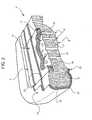
Figure 2 is an enlarged-scale cutaway view of the support body of the seat inFigure 1 . - In
Figure 1 , reference numeral 1 designates a seat comprising asquab 2 and abackrest 3, which are both made in a similar manner and so the following treatment, for the sake of simplicity, shall only make reference to thesquab 2. - As is shown in
Figure 2 , thesquab 2 comprises asupport body 4 defining anupper surface 5 shaped to support a user. Thesupport body 4 compriseslower padding 6 that is made of a plastic material foam, in particular a polyurethane foam, is connected to the vehicle in a known manner (not shown), and has adequate rigidity, resistance, elastic and/or density characteristics to support the user's weight and to ensure comfortable support. - The
padding 6 comprises anintermediate portion 7 having a plurality ofholes 8 that extend along respective, substantially vertical, parallel axes and pass through it from alower face 9 to anupper face 10 ofportion 7. The number, position and transversal section of theholes 8 are determined experimentally, as shall be described in more detail further on, in order to ensure heat dissipation and hence optimal comfort for thesupport body 4, without compromising the resistance and durability characteristics of thesquab 2. For example, theholes 8 are circular with a diameter of approximately 16 mm and there are twenty of them. -
Face 10 defines the bottom of aseating 11 that is located beneath anintermediate zone 12 ofsurface 5, where greater heat exchange takes place between the user and thesquab 2 in use. Theseating 11 has a substantially rectangular shape in plan (for example, with sides of 260 x 300 mm) and has a substantially constant height or depth (for example, equal to 15 mm). Along the two sides and at the back with respect to theseating 11, thepadding 6 comprises aportion 14 shaped so as to have aperipheral zone 15 of thesurface 5 that is raised with respect to theintermediate zone 12. - The
seating 11 is occupied, preferably completely, by an insert 16 (partially shown). Theinsert 16 has alower surface 17 that faces the openings of theholes 8 and that, preferably, rests directly againstface 10. - The
insert 16 has a constant thickness, equal to the depth of theseating 11, and has characteristics that allow air to pass through and transfer water vapour to theholes 8. In particular, theinsert 16 has permeability to the passage of air greater or equal to 39 l/min. Here and in the following, permeability to the passage of air is intended as being measured as the flow of air in litres per minute according to the UNI EN ISO 9237 standard (in detail, blowing air through a test sample, orthogonally to an area of 5 cm2, with a pressure difference of 200 Pa). - Preferably, the material of the
insert 16 also has a capacity of water absorption by capillarity greater than 2 mm. Here and in the following, the capacity of water absorption by capillarity is intended as being measured by immerging a test sample for five consecutive hours in a height-graduated container filled with at least 15 mm of water, at an ambient temperature of 20 °C and 50% relative air humidity, and corresponds to the height to which water absorption arrives with respect to the free surface of the water in the container, the test sample being defined by a 300 mm x 200 mm rectangular sheet positioned such that the 300 mm side is perpendicular to the bottom of the container. - In particular, the above-indicated limit for the water absorption capacity allows, in the case of the
backrest 3, to make the sensation of humidity perceived by the user as even as possible over the entireintermediate zone 12 of thesurface 5, avoiding drops of moisture stagnating at the bottom. - According to a first embodiment, the
insert 16 is made of open-cell polyurethane foam, having permeability to the passage of air of approximately 45 l/min and a capacity of water absorption by capillarity of approximately 8 mm. - In a second embodiment, the
insert 16 is made of a nonwoven fabric of polyester fibres coupled with low-melting polyester fibres, for example in a material with fibres belonging to the family of materials known by the commercial name of ECOTEN (registered trademark). In this way, for example, it is possible to choose an insert having a density of approximately 36.5 kg/m3, permeability to the passage of air of approximately 65 l/min or 39 l/min, and a capacity of water absorption by capillarity of approximately 2 mm or 4 mm. - In a further embodiment, the
insert 16 is made of a material known by the commercial name of "3mesh", from Müller Textil GmbH. - The
insert 16 andportion 14 are covered by acovering 20 comprising anouter layer 21 and aninner layer 22, which is defined by a sheet fixed tolayer 21, for example, by means of a flaming process. -
Layer 21 is defined by a fabric cover that is normally used in seats currently in production and that has a resistance to heat-exchange such as to impede the passage of heat during the phases of heating and cooling the covering 20, to render this heating/cooling gradual. - Preferably,
layer 22 extends over the entire inner surface oflayer 21. Alternatively,layer 22 has dimensions so as to cover just theinsert 16 beneathzone 12. -
Layer 22 is in contact with theinsert 16 and is made of a porous material having good air permeability and high hygroscopicity (or hydrophily), in order to absorb water vapour fromlayer 21 and maintain an acceptable level of comfort, limiting humidity on thesurface 5 in contact with the user. The absorbed humidity is then transferred to theholes 8 by means of the transpiration or permeability oflayer 22 itself and theinsert 16. - In particular, the term "hygroscopic" means a body and/or substance able to absorb humidity in the air and that changes in size due to this absorption, while the term "hydrophilic" means a body and/or substance able to absorb humidity in the air without its dimensions changing: for the purposes of the present invention, the difference in the meanings between these two terms is considered unimportant.
- As an index to check the hygroscopicity or hydrophily of
layer 22, a parameter known as "wettability" is evaluated, namely the time needed to completely wet a parallelepipedal test sample with a rectangular base, a volume of between 0.2 and 0.25 dm3 and having a height of at least 15 mm, initially dried and then left to float in a container filled with a quantity of water equal to at least the thickness of the test sample and hence at least 15 mm. - To have acceptable comfort in terms of sensation of heat and sensation of humidity, the material of
layer 22 has a wettability of less than or equal to 30 seconds. - Preferably, the material of
layer 22 also has a capacity of water absorption by capillarity greater or equal to 15 mm, in order to render the absorption of humidity between the various zones oflayer 22 as even as possible. - Preferably,
layer 22 also has permeability to the passage of air greater or equal to 95 l/min, to facilitate the passage of air and hence heat exchange between thesurface 5 and theholes 8. In particular, once thelayers - In one embodiment,
layer 22 has a thickness greater or equal to 3 mm, preferably equal to 6.5 mm, and is made of an open-cell foam, in particular a polyester-based polyurethane foam. In particular, a polyester-based expanded polyurethane, with respect to a polyether-based expanded polyurethane of the same density, has a regular cell structure, substantially constant cell sizes, greater hysteresis and less elasticity (therefore, greater impact absorption) and less resistance to water and heat. - For example, the material of
layer 22 is defined by a polyester-based expanded polyurethane known by the commercial name of WA35, from Toscana Gomma S.p.A., which has a wettability of approximately 10 seconds, a capacity of water absorption by capillarity of approximately 15 mm, a density of approximately 35 kg/m3 and an approximate number of 15 cells/cm. - With this material and with a thickness of 6.5 mm,
layer 22 has permeability to the passage of air of approximately 98 l/min. - As mentioned above, the heat exchange efficiency of the
support body 4 also depends on the number, size and positioning of theholes 8 in thepadding 6. In particular, the distribution of theholes 8 is not uniform alongface 10 and is determined via design and experimental evaluation, which comprises the following phases: - 1) a seat is designed and built having
solid padding 6, i.e. withoutholes 8; - 2) the zones of the seat where contact pressures are highest for a user or standard dummy are determined by design or experimental testing;
- 3) the built seat is subjected to an experimental test to define the temperature or heat profile on the support surface of the seat, keeping the seat in a environment of controlled and constant temperature and humidity, in particular an environment at a temperature of 25° C and 50% relative humidity, and performing the following operations:
- a) the seat is used for one hour, making a user (or standard dummy with outer surfaces heated to 35 °C) sit on the support surface of the seat;
- b) the temperature of the support surface is measured and a temperature map is defined by means of a thermographic system;
- c) operations 3a) and 3b) are repeated for a certain number of times (for example, another two times);
- d) a mean heat map is defined, with average temperature values at each point of the support surface, based on the number of thermographic readings taken;
- 4) the mean heat map is compared with the results of phase N° 2, to check that the higher temperature values are positioned in the zones with higher contact pressures, and in the case of a positive outcome, it is deduced that the results of phases N° 2 and 3 are reliable;
- 5) the number and size of the
holes 8 to be made in the padding are defined beforehand (for example, twenty holes with a diameter of 16 mm), without excessively decreasing the padding's characteristics of flexibility, resistance, carrying capacity, etc.; - 6) the positions of the
holes 8 are chosen by arranging the openings of theholes 8 in the padding in correspondence to the points that are marked by the highest temperature values on the mean heat map; - 7) the operations of phase N° 3 are repeated with the seat having perforated padding;
- 8) the new mean heat map is compared with the previous one to check the outcome of the choice made in phase N° 6.
- On the basis of that stated above, it is evident how the set of characteristics of the
support body 4 favour the passage of air and hence heat exchange and the transfer of water vapour from thesurface 5 to the outside via theholes 8, especially in stationary conditions. At the same time,layer 22, thanks to its own hygroscopic/hydrophilic capacity, frees thesurface 5 of humidity, which is easily transferred to theholes 8 thanks to the transpiration oflayer 22 itself and theinsert 16, to improve the user's perceived sensation with respect to known solutions. - In particular, with regards to thermal comfort, through experimental tests carried out with a "perspiring" dummy, sufficient heat exchange (approximately 70 W/m2) and evaporative exchange to avoid perspiration forming on the human body were detected.
- In particular, the dummy used in the tests has an anthropomorphous shape, basically comprising a back and a base and has a series of surface inserts that simulate human skin to reproduce the human body and thermoregulation system. The dummy is positioned on the seat under test so that dummy's weight generates realistic pressure on the backrest and the squab. Measurement of the transfer of heat and water vapour takes place under controlled environmental conditions, while keeping the dummy at a constant temperature of 35°C and at a fixed rate of perspiration, set via an electronic control system. The heat energy and the water vapour dissipated by the dummy represent a direct estimate of the thermal conductivity and permeability of the seat's backrest and squab.
- Finally, it is clear that various modifications and variants can be made to the
support body 4 described above with reference to the enclosed figures without leaving the scope of protection of the present invention, as defined in the enclosed claims. - In particular, the
seating 11 and theinsert 16 could have a different shape and/or incorporate one or more sensors, placed in positions that do not interfere with the openings of theholes 8 onface 10. - Furthermore, the hydrophilic material of
layer 22 could be different from that indicated above by way of example; in particular, it could be a fibre material, for example, a material in natural fibres.
Claims (12)
- Support body (4) of a seat for vehicles comprising:a) a padding (6) made of a plastic material foam and comprising an intermediate portion (7) having a plurality of through holes (8);- a breathable insert (16) facing the openings of said holes (8) ;- a covering (20) arranged to cover at least said insert (16) and comprising:a) an outer layer (21) defining a support surface (5) for a user, andb) an inner layer (22) facing said insert (16) and fixed with respect to said outer layer (21);characterized in that said inner layer (22) is made of a material having a wettability of less than or equal to 30 seconds; wettability being measured as the time necessary to completely wet a test sample, initially dried and then left to float in a container filled with a quantity of water equal to the thickness of the test sample.
- Support body of a seat according to claim 1,
characterized in that said inner layer (22) is made of a material having a capacity of water absorption by capillarity greater or equal to 15 mm, measured by immerging a test sample for five consecutive hours in a height-graduated container filled with at least 15 mm of water, at an ambient temperature of 20 °C and 50% relative air humidity, and corresponding to the height to which water absorption arrives with respect to the free surface of the water in the container; the test sample being defined by a 300 mm x 200 mm rectangular sheet positioned such that the 300 mm side is perpendicular to the bottom of the container. - Support body of a seat according to claim 1 or 2,
characterized in that said inner layer (22) has permeability to the passage of air greater or equal to 95 l/min, measured according to the UNI EN ISO 9237 standard. - Support body of a seat according to claim 3,
characterized in that said covering (20) has permeability to the passage of air greater or equal to 45 l/min. - Support body of a seat according to any of the previous claims, characterized in that said inner layer (22) is made of open-cell, polyester-based polyurethane foam.
- Support body of a seat according to any of the previous claims, characterized in that said insert (16) has permeability to the passage of air greater or equal to 39 l/min, measured according to the UNI EN ISO 9237 standard.
- Support body of a seat according to any of the previous claims, characterized in that said insert (16) is made of a material having a capacity of water absorption by capillarity greater than 2 mm, measured by immerging a test sample for five consecutive hours in a height-graduated container filled with at least 15 mm of water, at an ambient temperature of 20 °C and 50% relative air humidity, and corresponding to the height to which water absorption arrives with respect to the free surface of the water in the container, the test sample being defined by a 300 mm x 200 mm rectangular sheet positioned such that the 300 mm side is moved closer to the bottom of the container.
- Support body of a seat according to any of the previous claims, characterized in that said insert (16) is made of an open-cell polyurethane foam.
- Support body of a seat according to any of claims 1 to 7, characterized in that said insert (16) is made of a nonwoven fabric in polyester fibre.
- Support body of a seat according to any of the previous claims, characterized in that the distribution of said holes (8) in said intermediate portion (7) of said padding (6) is not uniform.
- Method to determine the distribution of a plurality of through holes (8) in the padding of a seat's support body, in particular a support body of a seat embodied according to claim 10; the method comprising the phases of:- providing a support body comprising:a) a padding made of a solid plastic material foam, andb) a covering (20) defining a support surface (5) for a user;- measuring the temperature of said support surface under conditions of use; the measurement phase comprising the operations ofa) keeping said support body in an environment of controlled and constant temperature and humidity,b) using said support body, by making a user or a dummy sit on said support surface for a preset time;c) measuring the temperature after use, by means of a thermographic measurement system so as to define a heat map of said support surface;- positioning the openings of said holes (8) in said padding (6) in correspondence to the points marked by the highest temperatures.
- Method according to claim 12, characterized in that it comprises the phases of:- determining the zones of the seat where the contact pressures are highest for a user or a standard dummy;- checking that the highest measured temperature values are located in the zones with the highest contact pressures.
Priority Applications (6)
| Application Number | Priority Date | Filing Date | Title |
|---|---|---|---|
| PL08425441T PL2138348T3 (en) | 2008-06-24 | 2008-06-24 | Support body of a seat for vehicles. |
| EP08425441.6A EP2138348B1 (en) | 2008-06-24 | 2008-06-24 | Support body of a seat for vehicles. |
| US13/000,616 US8491057B2 (en) | 2008-06-24 | 2009-06-23 | Support body of a seat for vehicles |
| EP09769223A EP2296937A1 (en) | 2008-06-24 | 2009-06-23 | Support body of a seat for vehicles |
| BRPI0910128A BRPI0910128A2 (en) | 2008-06-24 | 2009-06-23 | vehicle seat support body |
| PCT/EP2009/057767 WO2009156374A1 (en) | 2008-06-24 | 2009-06-23 | Support body of a seat for vehicles |
Applications Claiming Priority (1)
| Application Number | Priority Date | Filing Date | Title |
|---|---|---|---|
| EP08425441.6A EP2138348B1 (en) | 2008-06-24 | 2008-06-24 | Support body of a seat for vehicles. |
Publications (2)
| Publication Number | Publication Date |
|---|---|
| EP2138348A1 true EP2138348A1 (en) | 2009-12-30 |
| EP2138348B1 EP2138348B1 (en) | 2013-05-01 |
Family
ID=40303684
Family Applications (2)
| Application Number | Title | Priority Date | Filing Date |
|---|---|---|---|
| EP08425441.6A Not-in-force EP2138348B1 (en) | 2008-06-24 | 2008-06-24 | Support body of a seat for vehicles. |
| EP09769223A Withdrawn EP2296937A1 (en) | 2008-06-24 | 2009-06-23 | Support body of a seat for vehicles |
Family Applications After (1)
| Application Number | Title | Priority Date | Filing Date |
|---|---|---|---|
| EP09769223A Withdrawn EP2296937A1 (en) | 2008-06-24 | 2009-06-23 | Support body of a seat for vehicles |
Country Status (5)
| Country | Link |
|---|---|
| US (1) | US8491057B2 (en) |
| EP (2) | EP2138348B1 (en) |
| BR (1) | BRPI0910128A2 (en) |
| PL (1) | PL2138348T3 (en) |
| WO (1) | WO2009156374A1 (en) |
Cited By (3)
| Publication number | Priority date | Publication date | Assignee | Title |
|---|---|---|---|---|
| US20150079892A1 (en) * | 2013-07-09 | 2015-03-19 | I.G. Bauerhin Gmbh | Climatising device for a vehicle seat |
| WO2015091355A1 (en) * | 2013-12-20 | 2015-06-25 | Johnson Controls Gmbh | Foam part for a vehicle seat, and vehicle seat |
| CN110329403A (en) * | 2019-07-20 | 2019-10-15 | 弋有军 | Press type waterproof type shared bicycle seat |
Families Citing this family (11)
| Publication number | Priority date | Publication date | Assignee | Title |
|---|---|---|---|---|
| PL2138348T3 (en) | 2008-06-24 | 2013-09-30 | Fiat Ricerche | Support body of a seat for vehicles. |
| US20130059115A1 (en) * | 2011-09-05 | 2013-03-07 | Meng Chieh Lin | Pad with foam and fabric |
| US8690237B2 (en) * | 2012-06-07 | 2014-04-08 | Graco Children's Products Inc. | Child car seat and headrest with side impact energy absorption |
| US10246153B2 (en) * | 2012-10-11 | 2019-04-02 | Polaris Industries Inc. | Side-by-side vehicle |
| ME02166B (en) * | 2013-03-12 | 2015-10-20 | Boxmark Leather D O O | Multi layered covering material and process for making multi layered covering material for elements making furniture more comfortable comprising upholstery, cushions, blankets, and similar elements |
| EP3147156B1 (en) * | 2014-05-23 | 2019-08-07 | Dayou Holdings Co., Ltd. | Multi-hardness cushion for automobile and multi-hardness cushion having ventilation structure |
| CN108887961B (en) * | 2018-06-20 | 2021-10-15 | 新华网股份有限公司 | Seats and Seat-Based Concentration Assessment Methods |
| EP3892447A4 (en) * | 2018-12-03 | 2022-08-31 | Bridgestone Corporation | Porous structure, method for manufacturing porous structure, and cushion material for seat sheet |
| US11524613B2 (en) | 2020-12-28 | 2022-12-13 | Lear Corporation | Ventilated seat with low pressure zone induced airflow |
| US12377764B2 (en) * | 2022-02-28 | 2025-08-05 | Lear Corporation | Ventilated seat and method of making |
| DE102024129591A1 (en) | 2024-10-14 | 2025-01-02 | Dr. Ing. H.C. F. Porsche Aktiengesellschaft | Device and method for heating a vehicle seat and vehicle comprising the device |
Citations (5)
| Publication number | Priority date | Publication date | Assignee | Title |
|---|---|---|---|---|
| EP1389558A1 (en) * | 2002-08-15 | 2004-02-18 | Nhk Spring Co., Ltd. | Breathable seat |
| US20040189061A1 (en) * | 2001-07-28 | 2004-09-30 | Dirk Hartwich | Air-conditioned upholstered element for the seat of a motor vehicle |
| FR2868368A1 (en) * | 2004-03-31 | 2005-10-07 | Faurecia Sieges Automobile | Trim for motor vehicle seat with ventilated zone has covering material fixed to inner three-dimensional layer along seam line |
| FR2882308A1 (en) | 2005-02-22 | 2006-08-25 | Cera | Cushion production for motor vehicle seat, comprises disposing porous coating, air distribution layer and separation layers at mold tank, introducing studs into perforations, flowing mixture in the tank and placing the lid on the tank |
| EP1806258A1 (en) * | 2006-01-10 | 2007-07-11 | Volkswagen Aktiengesellschaft | Air-conditioned upholstered element, particularly for a passive air-conditioned seat |
Family Cites Families (21)
| Publication number | Priority date | Publication date | Assignee | Title |
|---|---|---|---|---|
| JPS5578916A (en) * | 1978-12-12 | 1980-06-14 | Yamada Kk | Carpet |
| US4534595A (en) * | 1981-12-29 | 1985-08-13 | Tachikawa Spring Co., Ltd. | Vehicle seat |
| GB2184010B (en) * | 1985-05-09 | 1988-12-07 | Tachi S Co | Seat |
| DE3617816A1 (en) * | 1986-04-04 | 1987-10-15 | Metzeler Schaum Gmbh | Process for producing an air-permeable upholstery part and upholstery part produced according to the process |
| US4718153A (en) * | 1986-04-10 | 1988-01-12 | Steelcase Inc. | Cushion manufacturing process |
| US4925513A (en) * | 1988-10-17 | 1990-05-15 | Hoover Universal, Inc. | Method for manufacturing contoured seats |
| AU658829B2 (en) * | 1991-08-27 | 1995-05-04 | Namba Press Works Co., Ltd. | Skin material back-coated with thin-film latex foam and integrated foamed product utilizing the skin material |
| US5429852A (en) * | 1992-12-21 | 1995-07-04 | Quinn; Raymond | Transportable chair pad |
| FR2707972B1 (en) * | 1993-06-29 | 1995-09-22 | Bfa | Improvements to the padding of motor vehicle seats. |
| US5858159A (en) * | 1995-04-25 | 1999-01-12 | Hoover Universal, Inc. | Method for manufacturing automotive seat assemblies using pre-bonded adhesives |
| JPH11506377A (en) * | 1995-06-07 | 1999-06-08 | ミネソタ マイニング アンド マニュファクチャリング カンパニー | Custom molded cushion and method |
| JP4540148B2 (en) * | 1998-08-07 | 2010-09-08 | 株式会社イノアックコーポレーション | Manufacturing method of cushion with skin material |
| US6620488B2 (en) | 1999-08-09 | 2003-09-16 | Inoac Corporation | Skin material, skinned cushion, and process for producing skinned cushion |
| US6345865B1 (en) * | 1998-12-28 | 2002-02-12 | T.S. Tech Co., Ltd. | Vehicle seat, a skin material for a vehicle seat and a method of manufacturing the vehicle seat |
| US6997514B2 (en) * | 2001-11-02 | 2006-02-14 | Lawrence J Tarantino | E.V.A. furniture |
| JP4060612B2 (en) * | 2002-02-28 | 2008-03-12 | 株式会社イノアックコーポレーション | Polyurethane foam for frame lamination |
| US6769146B2 (en) * | 2003-01-07 | 2004-08-03 | Milliken & Company | Transportation seat with release barrier fabrics |
| DE10350146B4 (en) * | 2003-10-28 | 2006-05-04 | Daimlerchrysler Ag | Vehicle seat for a motor vehicle |
| FR2869565B1 (en) * | 2004-04-28 | 2007-08-10 | Eurocopter France | PROTECTING A COMPOSITE STRUCTURE WITH IMPACTS |
| US7431982B2 (en) * | 2005-02-22 | 2008-10-07 | Inoac Corporation | Cushion sheet and manufacturing method for a cushion sheet |
| PL2138348T3 (en) | 2008-06-24 | 2013-09-30 | Fiat Ricerche | Support body of a seat for vehicles. |
-
2008
- 2008-06-24 PL PL08425441T patent/PL2138348T3/en unknown
- 2008-06-24 EP EP08425441.6A patent/EP2138348B1/en not_active Not-in-force
-
2009
- 2009-06-23 BR BRPI0910128A patent/BRPI0910128A2/en not_active IP Right Cessation
- 2009-06-23 US US13/000,616 patent/US8491057B2/en not_active Expired - Fee Related
- 2009-06-23 WO PCT/EP2009/057767 patent/WO2009156374A1/en not_active Ceased
- 2009-06-23 EP EP09769223A patent/EP2296937A1/en not_active Withdrawn
Patent Citations (5)
| Publication number | Priority date | Publication date | Assignee | Title |
|---|---|---|---|---|
| US20040189061A1 (en) * | 2001-07-28 | 2004-09-30 | Dirk Hartwich | Air-conditioned upholstered element for the seat of a motor vehicle |
| EP1389558A1 (en) * | 2002-08-15 | 2004-02-18 | Nhk Spring Co., Ltd. | Breathable seat |
| FR2868368A1 (en) * | 2004-03-31 | 2005-10-07 | Faurecia Sieges Automobile | Trim for motor vehicle seat with ventilated zone has covering material fixed to inner three-dimensional layer along seam line |
| FR2882308A1 (en) | 2005-02-22 | 2006-08-25 | Cera | Cushion production for motor vehicle seat, comprises disposing porous coating, air distribution layer and separation layers at mold tank, introducing studs into perforations, flowing mixture in the tank and placing the lid on the tank |
| EP1806258A1 (en) * | 2006-01-10 | 2007-07-11 | Volkswagen Aktiengesellschaft | Air-conditioned upholstered element, particularly for a passive air-conditioned seat |
Cited By (5)
| Publication number | Priority date | Publication date | Assignee | Title |
|---|---|---|---|---|
| US20150079892A1 (en) * | 2013-07-09 | 2015-03-19 | I.G. Bauerhin Gmbh | Climatising device for a vehicle seat |
| US11648857B2 (en) * | 2013-07-09 | 2023-05-16 | I.G. Bauerhin Gmbh | Ventilating device for a vehicle seat |
| WO2015091355A1 (en) * | 2013-12-20 | 2015-06-25 | Johnson Controls Gmbh | Foam part for a vehicle seat, and vehicle seat |
| CN110329403A (en) * | 2019-07-20 | 2019-10-15 | 弋有军 | Press type waterproof type shared bicycle seat |
| CN110329403B (en) * | 2019-07-20 | 2020-11-24 | 嘉兴极客旅游用品有限公司 | A push-type waterproof shared bicycle seat |
Also Published As
| Publication number | Publication date |
|---|---|
| US20110169319A1 (en) | 2011-07-14 |
| EP2138348B1 (en) | 2013-05-01 |
| EP2296937A1 (en) | 2011-03-23 |
| BRPI0910128A2 (en) | 2019-09-24 |
| PL2138348T3 (en) | 2013-09-30 |
| US8491057B2 (en) | 2013-07-23 |
| WO2009156374A1 (en) | 2009-12-30 |
Similar Documents
| Publication | Publication Date | Title |
|---|---|---|
| EP2138348B1 (en) | Support body of a seat for vehicles. | |
| US6064037A (en) | Air-permeable heating device for a seat | |
| US8584286B2 (en) | Systems and methods for providing a self deflating cushion | |
| EP2181887B1 (en) | Vehicle seat supporting body | |
| US9096158B2 (en) | Ventilated padding for a vehicle seat | |
| US20170028886A1 (en) | Air Conditioner Device for a Seat | |
| CN104736387B (en) | Seat with thermal | |
| US7695062B2 (en) | Device for receiving functional elements | |
| ES2485966T3 (en) | Covers reversible mattress | |
| KR102423961B1 (en) | cooling fabric | |
| US20070001506A1 (en) | Air-conditioning device for the passenger area of a vehicle | |
| JP2014533550A (en) | Support element and method for realizing it | |
| WO2015100591A1 (en) | Ventilation system | |
| CN105899402A (en) | Foam part, in particular for a vehicle seat, and vehicle seat | |
| JPWO2004012564A1 (en) | Air path for dehumidifier | |
| CN203511371U (en) | Breathable seat cushion and automobile seat | |
| JP3727812B2 (en) | Thermal chair | |
| TWM510682U (en) | Mat body with easy folding and ventilation effect | |
| CN111683570A (en) | Mattress | |
| CN1902066B (en) | Device for air conditioning a motor vehicle seat | |
| JP2007330459A (en) | Vehicle seat pad | |
| JP2011120519A (en) | Cooling mat for pet | |
| US20260008389A1 (en) | Method for estimating surface temperature of ventilated seat | |
| CA3183971C (en) | Ventilated seating assembly | |
| JPH11289896A (en) | Endothermic mat |
Legal Events
| Date | Code | Title | Description |
|---|---|---|---|
| PUAI | Public reference made under article 153(3) epc to a published international application that has entered the european phase |
Free format text: ORIGINAL CODE: 0009012 |
|
| AK | Designated contracting states |
Kind code of ref document: A1 Designated state(s): AT BE BG CH CY CZ DE DK EE ES FI FR GB GR HR HU IE IS IT LI LT LU LV MC MT NL NO PL PT RO SE SI SK TR |
|
| AX | Request for extension of the european patent |
Extension state: AL BA MK RS |
|
| 17P | Request for examination filed |
Effective date: 20100630 |
|
| 17Q | First examination report despatched |
Effective date: 20100726 |
|
| AKX | Designation fees paid |
Designated state(s): AT BE BG CH CY CZ DE DK EE ES FI FR GB GR HR HU IE IS IT LI LT LU LV MC MT NL NO PL PT RO SE SI SK TR |
|
| GRAP | Despatch of communication of intention to grant a patent |
Free format text: ORIGINAL CODE: EPIDOSNIGR1 |
|
| GRAP | Despatch of communication of intention to grant a patent |
Free format text: ORIGINAL CODE: EPIDOSNIGR1 |
|
| GRAS | Grant fee paid |
Free format text: ORIGINAL CODE: EPIDOSNIGR3 |
|
| GRAA | (expected) grant |
Free format text: ORIGINAL CODE: 0009210 |
|
| RIN1 | Information on inventor provided before grant (corrected) |
Inventor name: DEMONTIS, SALVATORE Inventor name: ZUSSINO, ANDREA |
|
| AK | Designated contracting states |
Kind code of ref document: B1 Designated state(s): AT BE BG CH CY CZ DE DK EE ES FI FR GB GR HR HU IE IS IT LI LT LU LV MC MT NL NO PL PT RO SE SI SK TR |
|
| REG | Reference to a national code |
Ref country code: GB Ref legal event code: FG4D |
|
| REG | Reference to a national code |
Ref country code: AT Ref legal event code: REF Ref document number: 609693 Country of ref document: AT Kind code of ref document: T Effective date: 20130515 Ref country code: CH Ref legal event code: EP |
|
| REG | Reference to a national code |
Ref country code: IE Ref legal event code: FG4D |
|
| REG | Reference to a national code |
Ref country code: DE Ref legal event code: R096 Ref document number: 602008024256 Country of ref document: DE Effective date: 20130627 |
|
| REG | Reference to a national code |
Ref country code: AT Ref legal event code: MK05 Ref document number: 609693 Country of ref document: AT Kind code of ref document: T Effective date: 20130501 |
|
| REG | Reference to a national code |
Ref country code: PL Ref legal event code: T3 |
|
| REG | Reference to a national code |
Ref country code: NL Ref legal event code: VDEP Effective date: 20130501 |
|
| REG | Reference to a national code |
Ref country code: LT Ref legal event code: MG4D |
|
| PG25 | Lapsed in a contracting state [announced via postgrant information from national office to epo] |
Ref country code: SI Free format text: LAPSE BECAUSE OF FAILURE TO SUBMIT A TRANSLATION OF THE DESCRIPTION OR TO PAY THE FEE WITHIN THE PRESCRIBED TIME-LIMIT Effective date: 20130501 Ref country code: FI Free format text: LAPSE BECAUSE OF FAILURE TO SUBMIT A TRANSLATION OF THE DESCRIPTION OR TO PAY THE FEE WITHIN THE PRESCRIBED TIME-LIMIT Effective date: 20130501 Ref country code: SE Free format text: LAPSE BECAUSE OF FAILURE TO SUBMIT A TRANSLATION OF THE DESCRIPTION OR TO PAY THE FEE WITHIN THE PRESCRIBED TIME-LIMIT Effective date: 20130501 Ref country code: LT Free format text: LAPSE BECAUSE OF FAILURE TO SUBMIT A TRANSLATION OF THE DESCRIPTION OR TO PAY THE FEE WITHIN THE PRESCRIBED TIME-LIMIT Effective date: 20130501 Ref country code: IS Free format text: LAPSE BECAUSE OF FAILURE TO SUBMIT A TRANSLATION OF THE DESCRIPTION OR TO PAY THE FEE WITHIN THE PRESCRIBED TIME-LIMIT Effective date: 20130901 Ref country code: PT Free format text: LAPSE BECAUSE OF FAILURE TO SUBMIT A TRANSLATION OF THE DESCRIPTION OR TO PAY THE FEE WITHIN THE PRESCRIBED TIME-LIMIT Effective date: 20130902 Ref country code: AT Free format text: LAPSE BECAUSE OF FAILURE TO SUBMIT A TRANSLATION OF THE DESCRIPTION OR TO PAY THE FEE WITHIN THE PRESCRIBED TIME-LIMIT Effective date: 20130501 Ref country code: ES Free format text: LAPSE BECAUSE OF FAILURE TO SUBMIT A TRANSLATION OF THE DESCRIPTION OR TO PAY THE FEE WITHIN THE PRESCRIBED TIME-LIMIT Effective date: 20130812 Ref country code: NO Free format text: LAPSE BECAUSE OF FAILURE TO SUBMIT A TRANSLATION OF THE DESCRIPTION OR TO PAY THE FEE WITHIN THE PRESCRIBED TIME-LIMIT Effective date: 20130801 Ref country code: GR Free format text: LAPSE BECAUSE OF FAILURE TO SUBMIT A TRANSLATION OF THE DESCRIPTION OR TO PAY THE FEE WITHIN THE PRESCRIBED TIME-LIMIT Effective date: 20130802 |
|
| PG25 | Lapsed in a contracting state [announced via postgrant information from national office to epo] |
Ref country code: CY Free format text: LAPSE BECAUSE OF FAILURE TO SUBMIT A TRANSLATION OF THE DESCRIPTION OR TO PAY THE FEE WITHIN THE PRESCRIBED TIME-LIMIT Effective date: 20130501 Ref country code: BG Free format text: LAPSE BECAUSE OF FAILURE TO SUBMIT A TRANSLATION OF THE DESCRIPTION OR TO PAY THE FEE WITHIN THE PRESCRIBED TIME-LIMIT Effective date: 20130801 Ref country code: HR Free format text: LAPSE BECAUSE OF FAILURE TO SUBMIT A TRANSLATION OF THE DESCRIPTION OR TO PAY THE FEE WITHIN THE PRESCRIBED TIME-LIMIT Effective date: 20130501 |
|
| PG25 | Lapsed in a contracting state [announced via postgrant information from national office to epo] |
Ref country code: LV Free format text: LAPSE BECAUSE OF FAILURE TO SUBMIT A TRANSLATION OF THE DESCRIPTION OR TO PAY THE FEE WITHIN THE PRESCRIBED TIME-LIMIT Effective date: 20130501 |
|
| PG25 | Lapsed in a contracting state [announced via postgrant information from national office to epo] |
Ref country code: BE Free format text: LAPSE BECAUSE OF FAILURE TO SUBMIT A TRANSLATION OF THE DESCRIPTION OR TO PAY THE FEE WITHIN THE PRESCRIBED TIME-LIMIT Effective date: 20130501 Ref country code: DK Free format text: LAPSE BECAUSE OF FAILURE TO SUBMIT A TRANSLATION OF THE DESCRIPTION OR TO PAY THE FEE WITHIN THE PRESCRIBED TIME-LIMIT Effective date: 20130501 Ref country code: CZ Free format text: LAPSE BECAUSE OF FAILURE TO SUBMIT A TRANSLATION OF THE DESCRIPTION OR TO PAY THE FEE WITHIN THE PRESCRIBED TIME-LIMIT Effective date: 20130501 Ref country code: MC Free format text: LAPSE BECAUSE OF FAILURE TO SUBMIT A TRANSLATION OF THE DESCRIPTION OR TO PAY THE FEE WITHIN THE PRESCRIBED TIME-LIMIT Effective date: 20130501 Ref country code: EE Free format text: LAPSE BECAUSE OF FAILURE TO SUBMIT A TRANSLATION OF THE DESCRIPTION OR TO PAY THE FEE WITHIN THE PRESCRIBED TIME-LIMIT Effective date: 20130501 Ref country code: SK Free format text: LAPSE BECAUSE OF FAILURE TO SUBMIT A TRANSLATION OF THE DESCRIPTION OR TO PAY THE FEE WITHIN THE PRESCRIBED TIME-LIMIT Effective date: 20130501 |
|
| REG | Reference to a national code |
Ref country code: CH Ref legal event code: PL |
|
| PG25 | Lapsed in a contracting state [announced via postgrant information from national office to epo] |
Ref country code: RO Free format text: LAPSE BECAUSE OF FAILURE TO SUBMIT A TRANSLATION OF THE DESCRIPTION OR TO PAY THE FEE WITHIN THE PRESCRIBED TIME-LIMIT Effective date: 20130501 Ref country code: NL Free format text: LAPSE BECAUSE OF FAILURE TO SUBMIT A TRANSLATION OF THE DESCRIPTION OR TO PAY THE FEE WITHIN THE PRESCRIBED TIME-LIMIT Effective date: 20130501 |
|
| PLBE | No opposition filed within time limit |
Free format text: ORIGINAL CODE: 0009261 |
|
| STAA | Information on the status of an ep patent application or granted ep patent |
Free format text: STATUS: NO OPPOSITION FILED WITHIN TIME LIMIT |
|
| REG | Reference to a national code |
Ref country code: IE Ref legal event code: MM4A |
|
| 26N | No opposition filed |
Effective date: 20140204 |
|
| GBPC | Gb: european patent ceased through non-payment of renewal fee |
Effective date: 20130801 |
|
| PG25 | Lapsed in a contracting state [announced via postgrant information from national office to epo] |
Ref country code: IE Free format text: LAPSE BECAUSE OF NON-PAYMENT OF DUE FEES Effective date: 20130624 Ref country code: CH Free format text: LAPSE BECAUSE OF NON-PAYMENT OF DUE FEES Effective date: 20130630 Ref country code: LI Free format text: LAPSE BECAUSE OF NON-PAYMENT OF DUE FEES Effective date: 20130630 |
|
| REG | Reference to a national code |
Ref country code: DE Ref legal event code: R097 Ref document number: 602008024256 Country of ref document: DE Effective date: 20140204 |
|
| PG25 | Lapsed in a contracting state [announced via postgrant information from national office to epo] |
Ref country code: GB Free format text: LAPSE BECAUSE OF NON-PAYMENT OF DUE FEES Effective date: 20130801 |
|
| PG25 | Lapsed in a contracting state [announced via postgrant information from national office to epo] |
Ref country code: MT Free format text: LAPSE BECAUSE OF FAILURE TO SUBMIT A TRANSLATION OF THE DESCRIPTION OR TO PAY THE FEE WITHIN THE PRESCRIBED TIME-LIMIT Effective date: 20130501 |
|
| REG | Reference to a national code |
Ref country code: FR Ref legal event code: PLFP Year of fee payment: 8 |
|
| PG25 | Lapsed in a contracting state [announced via postgrant information from national office to epo] |
Ref country code: LU Free format text: LAPSE BECAUSE OF NON-PAYMENT OF DUE FEES Effective date: 20130624 Ref country code: HU Free format text: LAPSE BECAUSE OF FAILURE TO SUBMIT A TRANSLATION OF THE DESCRIPTION OR TO PAY THE FEE WITHIN THE PRESCRIBED TIME-LIMIT; INVALID AB INITIO Effective date: 20080624 |
|
| PGFP | Annual fee paid to national office [announced via postgrant information from national office to epo] |
Ref country code: TR Payment date: 20150623 Year of fee payment: 8 Ref country code: DE Payment date: 20150616 Year of fee payment: 8 |
|
| PGFP | Annual fee paid to national office [announced via postgrant information from national office to epo] |
Ref country code: FR Payment date: 20150608 Year of fee payment: 8 Ref country code: PL Payment date: 20150527 Year of fee payment: 8 Ref country code: IT Payment date: 20150610 Year of fee payment: 8 |
|
| REG | Reference to a national code |
Ref country code: DE Ref legal event code: R119 Ref document number: 602008024256 Country of ref document: DE |
|
| REG | Reference to a national code |
Ref country code: FR Ref legal event code: ST Effective date: 20170228 |
|
| PG25 | Lapsed in a contracting state [announced via postgrant information from national office to epo] |
Ref country code: FR Free format text: LAPSE BECAUSE OF NON-PAYMENT OF DUE FEES Effective date: 20160630 Ref country code: DE Free format text: LAPSE BECAUSE OF NON-PAYMENT OF DUE FEES Effective date: 20170103 |
|
| PG25 | Lapsed in a contracting state [announced via postgrant information from national office to epo] |
Ref country code: IT Free format text: LAPSE BECAUSE OF NON-PAYMENT OF DUE FEES Effective date: 20160624 |
|
| PG25 | Lapsed in a contracting state [announced via postgrant information from national office to epo] |
Ref country code: PL Free format text: LAPSE BECAUSE OF NON-PAYMENT OF DUE FEES Effective date: 20160624 |
|
| PG25 | Lapsed in a contracting state [announced via postgrant information from national office to epo] |
Ref country code: TR Free format text: LAPSE BECAUSE OF NON-PAYMENT OF DUE FEES Effective date: 20160624 |