EP2138269A1 - Method for edging lens of glasses - Google Patents
Method for edging lens of glasses Download PDFInfo
- Publication number
- EP2138269A1 EP2138269A1 EP08722308A EP08722308A EP2138269A1 EP 2138269 A1 EP2138269 A1 EP 2138269A1 EP 08722308 A EP08722308 A EP 08722308A EP 08722308 A EP08722308 A EP 08722308A EP 2138269 A1 EP2138269 A1 EP 2138269A1
- Authority
- EP
- European Patent Office
- Prior art keywords
- lens
- processing
- processing target
- shape
- group
- Prior art date
- Legal status (The legal status is an assumption and is not a legal conclusion. Google has not performed a legal analysis and makes no representation as to the accuracy of the status listed.)
- Withdrawn
Links
- 238000000034 method Methods 0.000 title claims description 41
- 238000007688 edging Methods 0.000 title claims description 33
- 239000011521 glass Substances 0.000 title 1
- 238000012545 processing Methods 0.000 claims abstract description 308
- 230000003287 optical effect Effects 0.000 claims description 32
- 238000005259 measurement Methods 0.000 claims description 18
- 230000000007 visual effect Effects 0.000 claims description 3
- -1 polyethylene terephthalate Polymers 0.000 description 40
- 150000001875 compounds Chemical class 0.000 description 33
- 125000004432 carbon atom Chemical group C* 0.000 description 24
- 239000005871 repellent Substances 0.000 description 23
- 239000000463 material Substances 0.000 description 20
- 239000002904 solvent Substances 0.000 description 17
- 239000010702 perfluoropolyether Substances 0.000 description 15
- ATUOYWHBWRKTHZ-UHFFFAOYSA-N Propane Chemical compound CCC ATUOYWHBWRKTHZ-UHFFFAOYSA-N 0.000 description 14
- 239000001257 hydrogen Substances 0.000 description 14
- 229910052739 hydrogen Inorganic materials 0.000 description 14
- 150000003961 organosilicon compounds Chemical class 0.000 description 14
- 238000000227 grinding Methods 0.000 description 13
- 229910052710 silicon Inorganic materials 0.000 description 13
- XUIMIQQOPSSXEZ-UHFFFAOYSA-N Silicon Chemical compound [Si] XUIMIQQOPSSXEZ-UHFFFAOYSA-N 0.000 description 12
- 239000010703 silicon Substances 0.000 description 12
- VYPSYNLAJGMNEJ-UHFFFAOYSA-N Silicium dioxide Chemical compound O=[Si]=O VYPSYNLAJGMNEJ-UHFFFAOYSA-N 0.000 description 11
- 125000000217 alkyl group Chemical group 0.000 description 11
- 125000002496 methyl group Chemical group [H]C([H])([H])* 0.000 description 11
- 239000011368 organic material Substances 0.000 description 11
- 125000001997 phenyl group Chemical group [H]C1=C([H])C([H])=C(*)C([H])=C1[H] 0.000 description 11
- UFHFLCQGNIYNRP-UHFFFAOYSA-N Hydrogen Chemical compound [H][H] UFHFLCQGNIYNRP-UHFFFAOYSA-N 0.000 description 10
- 150000002430 hydrocarbons Chemical group 0.000 description 10
- 150000002894 organic compounds Chemical class 0.000 description 10
- UHOVQNZJYSORNB-UHFFFAOYSA-N Benzene Chemical compound C1=CC=CC=C1 UHOVQNZJYSORNB-UHFFFAOYSA-N 0.000 description 9
- 238000004519 manufacturing process Methods 0.000 description 9
- 238000012937 correction Methods 0.000 description 7
- 125000001495 ethyl group Chemical group [H]C([H])([H])C([H])([H])* 0.000 description 7
- OFBQJSOFQDEBGM-UHFFFAOYSA-N n-pentane Natural products CCCCC OFBQJSOFQDEBGM-UHFFFAOYSA-N 0.000 description 7
- 239000001294 propane Substances 0.000 description 7
- 150000004756 silanes Chemical class 0.000 description 7
- XKRFYHLGVUSROY-UHFFFAOYSA-N Argon Chemical compound [Ar] XKRFYHLGVUSROY-UHFFFAOYSA-N 0.000 description 6
- OKTJSMMVPCPJKN-UHFFFAOYSA-N Carbon Chemical compound [C] OKTJSMMVPCPJKN-UHFFFAOYSA-N 0.000 description 6
- 229910052799 carbon Inorganic materials 0.000 description 6
- 229920001577 copolymer Polymers 0.000 description 6
- 238000000151 deposition Methods 0.000 description 6
- 230000008021 deposition Effects 0.000 description 6
- 239000007788 liquid Substances 0.000 description 6
- VNWKTOKETHGBQD-UHFFFAOYSA-N methane Chemical compound C VNWKTOKETHGBQD-UHFFFAOYSA-N 0.000 description 6
- GRVDJDISBSALJP-UHFFFAOYSA-N methyloxidanyl Chemical compound [O]C GRVDJDISBSALJP-UHFFFAOYSA-N 0.000 description 6
- VLKZOEOYAKHREP-UHFFFAOYSA-N n-Hexane Chemical compound CCCCCC VLKZOEOYAKHREP-UHFFFAOYSA-N 0.000 description 6
- 239000000126 substance Substances 0.000 description 6
- 125000000113 cyclohexyl group Chemical group [H]C1([H])C([H])([H])C([H])([H])C([H])(*)C([H])([H])C1([H])[H] 0.000 description 5
- 238000010438 heat treatment Methods 0.000 description 5
- 229910052751 metal Inorganic materials 0.000 description 5
- 239000002184 metal Substances 0.000 description 5
- 125000000956 methoxy group Chemical group [H]C([H])([H])O* 0.000 description 5
- BPUBBGLMJRNUCC-UHFFFAOYSA-N oxygen(2-);tantalum(5+) Chemical compound [O-2].[O-2].[O-2].[O-2].[O-2].[Ta+5].[Ta+5] BPUBBGLMJRNUCC-UHFFFAOYSA-N 0.000 description 5
- 230000002093 peripheral effect Effects 0.000 description 5
- 229920003023 plastic Polymers 0.000 description 5
- 239000004033 plastic Substances 0.000 description 5
- 125000001436 propyl group Chemical group [H]C([*])([H])C([H])([H])C([H])([H])[H] 0.000 description 5
- 229910000077 silane Inorganic materials 0.000 description 5
- 239000000377 silicon dioxide Substances 0.000 description 5
- LFQSCWFLJHTTHZ-UHFFFAOYSA-N Ethanol Chemical compound CCO LFQSCWFLJHTTHZ-UHFFFAOYSA-N 0.000 description 4
- VVQNEPGJFQJSBK-UHFFFAOYSA-N Methyl methacrylate Chemical compound COC(=O)C(C)=C VVQNEPGJFQJSBK-UHFFFAOYSA-N 0.000 description 4
- 125000003545 alkoxy group Chemical group 0.000 description 4
- 125000003277 amino group Chemical group 0.000 description 4
- QVGXLLKOCUKJST-UHFFFAOYSA-N atomic oxygen Chemical compound [O] QVGXLLKOCUKJST-UHFFFAOYSA-N 0.000 description 4
- 239000011248 coating agent Substances 0.000 description 4
- 238000000576 coating method Methods 0.000 description 4
- 238000001514 detection method Methods 0.000 description 4
- 230000000694 effects Effects 0.000 description 4
- 125000001033 ether group Chemical group 0.000 description 4
- 125000001301 ethoxy group Chemical group [H]C([H])([H])C([H])([H])O* 0.000 description 4
- 239000011147 inorganic material Substances 0.000 description 4
- 238000000869 ion-assisted deposition Methods 0.000 description 4
- 239000000178 monomer Substances 0.000 description 4
- 239000001301 oxygen Substances 0.000 description 4
- 229910052760 oxygen Inorganic materials 0.000 description 4
- 230000000704 physical effect Effects 0.000 description 4
- 235000012239 silicon dioxide Nutrition 0.000 description 4
- 229910001936 tantalum oxide Inorganic materials 0.000 description 4
- 125000004066 1-hydroxyethyl group Chemical group [H]OC([H])([*])C([H])([H])[H] 0.000 description 3
- ZWEHNKRNPOVVGH-UHFFFAOYSA-N 2-Butanone Chemical compound CCC(C)=O ZWEHNKRNPOVVGH-UHFFFAOYSA-N 0.000 description 3
- 125000003903 2-propenyl group Chemical group [H]C([*])([H])C([H])=C([H])[H] 0.000 description 3
- CSCPPACGZOOCGX-UHFFFAOYSA-N Acetone Chemical compound CC(C)=O CSCPPACGZOOCGX-UHFFFAOYSA-N 0.000 description 3
- OKKJLVBELUTLKV-UHFFFAOYSA-N Methanol Chemical compound OC OKKJLVBELUTLKV-UHFFFAOYSA-N 0.000 description 3
- PXHVJJICTQNCMI-UHFFFAOYSA-N Nickel Chemical compound [Ni] PXHVJJICTQNCMI-UHFFFAOYSA-N 0.000 description 3
- UCKMPCXJQFINFW-UHFFFAOYSA-N Sulphide Chemical compound [S-2] UCKMPCXJQFINFW-UHFFFAOYSA-N 0.000 description 3
- YXFVVABEGXRONW-UHFFFAOYSA-N Toluene Chemical compound CC1=CC=CC=C1 YXFVVABEGXRONW-UHFFFAOYSA-N 0.000 description 3
- 239000007983 Tris buffer Substances 0.000 description 3
- 239000002390 adhesive tape Substances 0.000 description 3
- 229910052786 argon Inorganic materials 0.000 description 3
- 239000001273 butane Substances 0.000 description 3
- 125000000484 butyl group Chemical group [H]C([*])([H])C([H])([H])C([H])([H])C([H])([H])[H] 0.000 description 3
- 238000006243 chemical reaction Methods 0.000 description 3
- 229910052801 chlorine Inorganic materials 0.000 description 3
- 125000001309 chloro group Chemical group Cl* 0.000 description 3
- 239000007789 gas Substances 0.000 description 3
- 125000005843 halogen group Chemical group 0.000 description 3
- 125000004435 hydrogen atom Chemical group [H]* 0.000 description 3
- IJDNQMDRQITEOD-UHFFFAOYSA-N n-butane Chemical compound CCCC IJDNQMDRQITEOD-UHFFFAOYSA-N 0.000 description 3
- 239000010955 niobium Substances 0.000 description 3
- 125000000962 organic group Chemical group 0.000 description 3
- BASFCYQUMIYNBI-UHFFFAOYSA-N platinum Chemical compound [Pt] BASFCYQUMIYNBI-UHFFFAOYSA-N 0.000 description 3
- 229920001296 polysiloxane Polymers 0.000 description 3
- 230000001681 protective effect Effects 0.000 description 3
- 230000009257 reactivity Effects 0.000 description 3
- 239000011347 resin Substances 0.000 description 3
- 229920005989 resin Polymers 0.000 description 3
- 125000000446 sulfanediyl group Chemical group *S* 0.000 description 3
- 150000003553 thiiranes Chemical group 0.000 description 3
- 239000010936 titanium Substances 0.000 description 3
- SJBBXFLOLUTGCW-UHFFFAOYSA-N 1,3-bis(trifluoromethyl)benzene Chemical compound FC(F)(F)C1=CC=CC(C(F)(F)F)=C1 SJBBXFLOLUTGCW-UHFFFAOYSA-N 0.000 description 2
- JHQVCQDWGSXTFE-UHFFFAOYSA-N 2-(2-prop-2-enoxycarbonyloxyethoxy)ethyl prop-2-enyl carbonate Chemical compound C=CCOC(=O)OCCOCCOC(=O)OCC=C JHQVCQDWGSXTFE-UHFFFAOYSA-N 0.000 description 2
- AOBIOSPNXBMOAT-UHFFFAOYSA-N 2-[2-(oxiran-2-ylmethoxy)ethoxymethyl]oxirane Chemical compound C1OC1COCCOCC1CO1 AOBIOSPNXBMOAT-UHFFFAOYSA-N 0.000 description 2
- IJGRMHOSHXDMSA-UHFFFAOYSA-N Atomic nitrogen Chemical compound N#N IJGRMHOSHXDMSA-UHFFFAOYSA-N 0.000 description 2
- SOGAXMICEFXMKE-UHFFFAOYSA-N Butylmethacrylate Chemical compound CCCCOC(=O)C(C)=C SOGAXMICEFXMKE-UHFFFAOYSA-N 0.000 description 2
- RTZKZFJDLAIYFH-UHFFFAOYSA-N Diethyl ether Chemical compound CCOCC RTZKZFJDLAIYFH-UHFFFAOYSA-N 0.000 description 2
- OTMSDBZUPAUEDD-UHFFFAOYSA-N Ethane Chemical compound CC OTMSDBZUPAUEDD-UHFFFAOYSA-N 0.000 description 2
- JOYRKODLDBILNP-UHFFFAOYSA-N Ethyl urethane Chemical compound CCOC(N)=O JOYRKODLDBILNP-UHFFFAOYSA-N 0.000 description 2
- KFZMGEQAYNKOFK-UHFFFAOYSA-N Isopropanol Chemical compound CC(C)O KFZMGEQAYNKOFK-UHFFFAOYSA-N 0.000 description 2
- PMDCZENCAXMSOU-UHFFFAOYSA-N N-ethylacetamide Chemical group CCNC(C)=O PMDCZENCAXMSOU-UHFFFAOYSA-N 0.000 description 2
- OHLUUHNLEMFGTQ-UHFFFAOYSA-N N-methylacetamide Chemical group CNC(C)=O OHLUUHNLEMFGTQ-UHFFFAOYSA-N 0.000 description 2
- 239000004793 Polystyrene Substances 0.000 description 2
- PPBRXRYQALVLMV-UHFFFAOYSA-N Styrene Chemical compound C=CC1=CC=CC=C1 PPBRXRYQALVLMV-UHFFFAOYSA-N 0.000 description 2
- NINIDFKCEFEMDL-UHFFFAOYSA-N Sulfur Chemical compound [S] NINIDFKCEFEMDL-UHFFFAOYSA-N 0.000 description 2
- BOTDANWDWHJENH-UHFFFAOYSA-N Tetraethyl orthosilicate Chemical compound CCO[Si](OCC)(OCC)OCC BOTDANWDWHJENH-UHFFFAOYSA-N 0.000 description 2
- 230000001133 acceleration Effects 0.000 description 2
- PXAJQJMDEXJWFB-UHFFFAOYSA-N acetone oxime Chemical group CC(C)=NO PXAJQJMDEXJWFB-UHFFFAOYSA-N 0.000 description 2
- 125000003668 acetyloxy group Chemical group [H]C([H])([H])C(=O)O[*] 0.000 description 2
- 125000003302 alkenyloxy group Chemical group 0.000 description 2
- 125000005083 alkoxyalkoxy group Chemical group 0.000 description 2
- 125000005336 allyloxy group Chemical group 0.000 description 2
- 125000003368 amide group Chemical group 0.000 description 2
- 125000002344 aminooxy group Chemical group [H]N([H])O[*] 0.000 description 2
- 125000001231 benzoyloxy group Chemical group C(C1=CC=CC=C1)(=O)O* 0.000 description 2
- 230000015572 biosynthetic process Effects 0.000 description 2
- 125000004106 butoxy group Chemical group [*]OC([H])([H])C([H])([H])C(C([H])([H])[H])([H])[H] 0.000 description 2
- 239000003795 chemical substances by application Substances 0.000 description 2
- 238000009833 condensation Methods 0.000 description 2
- 230000005494 condensation Effects 0.000 description 2
- 230000007423 decrease Effects 0.000 description 2
- 229910003460 diamond Inorganic materials 0.000 description 2
- 239000010432 diamond Substances 0.000 description 2
- ZUOUZKKEUPVFJK-UHFFFAOYSA-N diphenyl Chemical compound C1=CC=CC=C1C1=CC=CC=C1 ZUOUZKKEUPVFJK-UHFFFAOYSA-N 0.000 description 2
- 238000007598 dipping method Methods 0.000 description 2
- 125000003700 epoxy group Chemical group 0.000 description 2
- FFUAGWLWBBFQJT-UHFFFAOYSA-N hexamethyldisilazane Chemical compound C[Si](C)(C)N[Si](C)(C)C FFUAGWLWBBFQJT-UHFFFAOYSA-N 0.000 description 2
- 125000004051 hexyl group Chemical group [H]C([H])([H])C([H])([H])C([H])([H])C([H])([H])C([H])([H])C([H])([H])* 0.000 description 2
- 229920001519 homopolymer Polymers 0.000 description 2
- 150000002431 hydrogen Chemical class 0.000 description 2
- 230000007062 hydrolysis Effects 0.000 description 2
- 238000006460 hydrolysis reaction Methods 0.000 description 2
- 229910010272 inorganic material Inorganic materials 0.000 description 2
- 230000001050 lubricating effect Effects 0.000 description 2
- 238000005461 lubrication Methods 0.000 description 2
- 125000000250 methylamino group Chemical group [H]N(*)C([H])([H])[H] 0.000 description 2
- 239000000203 mixture Substances 0.000 description 2
- WHIVNJATOVLWBW-UHFFFAOYSA-N n-butan-2-ylidenehydroxylamine Chemical group CCC(C)=NO WHIVNJATOVLWBW-UHFFFAOYSA-N 0.000 description 2
- NCCHARWOCKOHIH-UHFFFAOYSA-N n-methylbenzamide Chemical group CNC(=O)C1=CC=CC=C1 NCCHARWOCKOHIH-UHFFFAOYSA-N 0.000 description 2
- NAQQTJZRCYNBRX-UHFFFAOYSA-N n-pentan-3-ylidenehydroxylamine Chemical group CCC(CC)=NO NAQQTJZRCYNBRX-UHFFFAOYSA-N 0.000 description 2
- 229910052758 niobium Inorganic materials 0.000 description 2
- GUCVJGMIXFAOAE-UHFFFAOYSA-N niobium atom Chemical compound [Nb] GUCVJGMIXFAOAE-UHFFFAOYSA-N 0.000 description 2
- AIRCTMFFNKZQPN-UHFFFAOYSA-N oxidoaluminium Chemical compound [Al]=O AIRCTMFFNKZQPN-UHFFFAOYSA-N 0.000 description 2
- TWNQGVIAIRXVLR-UHFFFAOYSA-N oxo(oxoalumanyloxy)alumane Chemical compound O=[Al]O[Al]=O TWNQGVIAIRXVLR-UHFFFAOYSA-N 0.000 description 2
- 125000004430 oxygen atom Chemical group O* 0.000 description 2
- 125000001147 pentyl group Chemical group C(CCCC)* 0.000 description 2
- 125000006551 perfluoro alkylene group Chemical group 0.000 description 2
- FYJQJMIEZVMYSD-UHFFFAOYSA-N perfluoro-2-butyltetrahydrofuran Chemical compound FC(F)(F)C(F)(F)C(F)(F)C(F)(F)C1(F)OC(F)(F)C(F)(F)C1(F)F FYJQJMIEZVMYSD-UHFFFAOYSA-N 0.000 description 2
- RVZRBWKZFJCCIB-UHFFFAOYSA-N perfluorotributylamine Chemical compound FC(F)(F)C(F)(F)C(F)(F)C(F)(F)N(C(F)(F)C(F)(F)C(F)(F)C(F)(F)F)C(F)(F)C(F)(F)C(F)(F)C(F)(F)F RVZRBWKZFJCCIB-UHFFFAOYSA-N 0.000 description 2
- 229920000515 polycarbonate Polymers 0.000 description 2
- 239000004417 polycarbonate Substances 0.000 description 2
- 229920000139 polyethylene terephthalate Polymers 0.000 description 2
- 229920002223 polystyrene Polymers 0.000 description 2
- 229920002578 polythiourethane polymer Polymers 0.000 description 2
- 229920002635 polyurethane Polymers 0.000 description 2
- 239000004814 polyurethane Substances 0.000 description 2
- 229920000915 polyvinyl chloride Polymers 0.000 description 2
- 239000004800 polyvinyl chloride Substances 0.000 description 2
- 230000003449 preventive effect Effects 0.000 description 2
- 238000003672 processing method Methods 0.000 description 2
- BDERNNFJNOPAEC-UHFFFAOYSA-N propan-1-ol Chemical compound CCCO BDERNNFJNOPAEC-UHFFFAOYSA-N 0.000 description 2
- 125000002572 propoxy group Chemical group [*]OC([H])([H])C(C([H])([H])[H])([H])[H] 0.000 description 2
- 229920006395 saturated elastomer Polymers 0.000 description 2
- 229930195734 saturated hydrocarbon Natural products 0.000 description 2
- 229910021332 silicide Inorganic materials 0.000 description 2
- FVBUAEGBCNSCDD-UHFFFAOYSA-N silicide(4-) Chemical compound [Si-4] FVBUAEGBCNSCDD-UHFFFAOYSA-N 0.000 description 2
- LIVNPJMFVYWSIS-UHFFFAOYSA-N silicon monoxide Chemical compound [Si-]#[O+] LIVNPJMFVYWSIS-UHFFFAOYSA-N 0.000 description 2
- 239000004575 stone Substances 0.000 description 2
- 229910052717 sulfur Inorganic materials 0.000 description 2
- 239000011593 sulfur Substances 0.000 description 2
- 238000012360 testing method Methods 0.000 description 2
- 125000004055 thiomethyl group Chemical group [H]SC([H])([H])* 0.000 description 2
- 229910052719 titanium Inorganic materials 0.000 description 2
- AQRLNPVMDITEJU-UHFFFAOYSA-N triethylsilane Chemical compound CC[SiH](CC)CC AQRLNPVMDITEJU-UHFFFAOYSA-N 0.000 description 2
- 229930195735 unsaturated hydrocarbon Natural products 0.000 description 2
- 229920006305 unsaturated polyester Polymers 0.000 description 2
- 125000000391 vinyl group Chemical group [H]C([*])=C([H])[H] 0.000 description 2
- IDXCKOANSQIPGX-UHFFFAOYSA-N (acetyloxy-ethenyl-methylsilyl) acetate Chemical compound CC(=O)O[Si](C)(C=C)OC(C)=O IDXCKOANSQIPGX-UHFFFAOYSA-N 0.000 description 1
- AWFOOUAPWFZKQK-UHFFFAOYSA-N (acetyloxy-methyl-phenylsilyl) acetate Chemical compound CC(=O)O[Si](C)(OC(C)=O)C1=CC=CC=C1 AWFOOUAPWFZKQK-UHFFFAOYSA-N 0.000 description 1
- KWEKXPWNFQBJAY-UHFFFAOYSA-N (dimethyl-$l^{3}-silanyl)oxy-dimethylsilicon Chemical compound C[Si](C)O[Si](C)C KWEKXPWNFQBJAY-UHFFFAOYSA-N 0.000 description 1
- GETTZEONDQJALK-UHFFFAOYSA-N (trifluoromethyl)benzene Chemical compound FC(F)(F)C1=CC=CC=C1 GETTZEONDQJALK-UHFFFAOYSA-N 0.000 description 1
- OKIYQFLILPKULA-UHFFFAOYSA-N 1,1,1,2,2,3,3,4,4-nonafluoro-4-methoxybutane Chemical compound COC(F)(F)C(F)(F)C(F)(F)C(F)(F)F OKIYQFLILPKULA-UHFFFAOYSA-N 0.000 description 1
- PGRNEGLBSNLPNP-UHFFFAOYSA-N 1,6-dichloro-3-methylhex-1-ene Chemical compound ClC=CC(C)CCCCl PGRNEGLBSNLPNP-UHFFFAOYSA-N 0.000 description 1
- UWFRVQVNYNPBEF-UHFFFAOYSA-N 1-(2,4-dimethylphenyl)propan-1-one Chemical compound CCC(=O)C1=CC=C(C)C=C1C UWFRVQVNYNPBEF-UHFFFAOYSA-N 0.000 description 1
- KMPBCFZCRNKXSA-UHFFFAOYSA-N 2,2,4,4,6,6-hexaethyl-1,3,5,2,4,6-trioxatrisilinane Chemical compound CC[Si]1(CC)O[Si](CC)(CC)O[Si](CC)(CC)O1 KMPBCFZCRNKXSA-UHFFFAOYSA-N 0.000 description 1
- WGGNJZRNHUJNEM-UHFFFAOYSA-N 2,2,4,4,6,6-hexamethyl-1,3,5,2,4,6-triazatrisilinane Chemical compound C[Si]1(C)N[Si](C)(C)N[Si](C)(C)N1 WGGNJZRNHUJNEM-UHFFFAOYSA-N 0.000 description 1
- IVIDDMGBRCPGLJ-UHFFFAOYSA-N 2,3-bis(oxiran-2-ylmethoxy)propan-1-ol Chemical compound C1OC1COC(CO)COCC1CO1 IVIDDMGBRCPGLJ-UHFFFAOYSA-N 0.000 description 1
- WZJUBBHODHNQPW-UHFFFAOYSA-N 2,4,6,8-tetramethyl-1,3,5,7,2$l^{3},4$l^{3},6$l^{3},8$l^{3}-tetraoxatetrasilocane Chemical compound C[Si]1O[Si](C)O[Si](C)O[Si](C)O1 WZJUBBHODHNQPW-UHFFFAOYSA-N 0.000 description 1
- SDMYZIQYGCCLHR-UHFFFAOYSA-N 2,5-bis(thiiran-2-ylmethylsulfanylmethyl)-1,4-dithiane Chemical compound C1SC1CSCC(SC1)CSC1CSCC1CS1 SDMYZIQYGCCLHR-UHFFFAOYSA-N 0.000 description 1
- STMDPCBYJCIZOD-UHFFFAOYSA-N 2-(2,4-dinitroanilino)-4-methylpentanoic acid Chemical compound CC(C)CC(C(O)=O)NC1=CC=C([N+]([O-])=O)C=C1[N+]([O-])=O STMDPCBYJCIZOD-UHFFFAOYSA-N 0.000 description 1
- SNGZGCFWZHOVOS-UHFFFAOYSA-N 2-(2-methyloctoxymethyl)oxirane Chemical compound CCCCCCC(C)COCC1CO1 SNGZGCFWZHOVOS-UHFFFAOYSA-N 0.000 description 1
- YSUQLAYJZDEMOT-UHFFFAOYSA-N 2-(butoxymethyl)oxirane Chemical compound CCCCOCC1CO1 YSUQLAYJZDEMOT-UHFFFAOYSA-N 0.000 description 1
- NPKKFQUHBHQTSH-UHFFFAOYSA-N 2-(decoxymethyl)oxirane Chemical compound CCCCCCCCCCOCC1CO1 NPKKFQUHBHQTSH-UHFFFAOYSA-N 0.000 description 1
- JKNCOURZONDCGV-UHFFFAOYSA-N 2-(dimethylamino)ethyl 2-methylprop-2-enoate Chemical compound CN(C)CCOC(=O)C(C)=C JKNCOURZONDCGV-UHFFFAOYSA-N 0.000 description 1
- LKMJVFRMDSNFRT-UHFFFAOYSA-N 2-(methoxymethyl)oxirane Chemical compound COCC1CO1 LKMJVFRMDSNFRT-UHFFFAOYSA-N 0.000 description 1
- ZXJBWUAALADCRI-UHFFFAOYSA-N 2-(octadecoxymethyl)oxirane Chemical compound CCCCCCCCCCCCCCCCCCOCC1CO1 ZXJBWUAALADCRI-UHFFFAOYSA-N 0.000 description 1
- GQTBMBMBWQJACJ-UHFFFAOYSA-N 2-[(4-butan-2-ylphenoxy)methyl]oxirane Chemical compound C1=CC(C(C)CC)=CC=C1OCC1OC1 GQTBMBMBWQJACJ-UHFFFAOYSA-N 0.000 description 1
- HHRACYLRBOUBKM-UHFFFAOYSA-N 2-[(4-tert-butylphenoxy)methyl]oxirane Chemical compound C1=CC(C(C)(C)C)=CC=C1OCC1OC1 HHRACYLRBOUBKM-UHFFFAOYSA-N 0.000 description 1
- SYEWHONLFGZGLK-UHFFFAOYSA-N 2-[1,3-bis(oxiran-2-ylmethoxy)propan-2-yloxymethyl]oxirane Chemical compound C1OC1COCC(OCC1OC1)COCC1CO1 SYEWHONLFGZGLK-UHFFFAOYSA-N 0.000 description 1
- HDPLHDGYGLENEI-UHFFFAOYSA-N 2-[1-(oxiran-2-ylmethoxy)propan-2-yloxymethyl]oxirane Chemical compound C1OC1COC(C)COCC1CO1 HDPLHDGYGLENEI-UHFFFAOYSA-N 0.000 description 1
- FVCHRIQAIOHAIC-UHFFFAOYSA-N 2-[1-[1-[1-(oxiran-2-ylmethoxy)propan-2-yloxy]propan-2-yloxy]propan-2-yloxymethyl]oxirane Chemical compound C1OC1COC(C)COC(C)COC(C)COCC1CO1 FVCHRIQAIOHAIC-UHFFFAOYSA-N 0.000 description 1
- SLQDZZGEPQYECP-UHFFFAOYSA-N 2-[2-(thiiran-2-ylmethylsulfanyl)ethylsulfanylmethyl]thiirane Chemical compound C1SC1CSCCSCC1CS1 SLQDZZGEPQYECP-UHFFFAOYSA-N 0.000 description 1
- SEFYJVFBMNOLBK-UHFFFAOYSA-N 2-[2-[2-(oxiran-2-ylmethoxy)ethoxy]ethoxymethyl]oxirane Chemical compound C1OC1COCCOCCOCC1CO1 SEFYJVFBMNOLBK-UHFFFAOYSA-N 0.000 description 1
- WTYYGFLRBWMFRY-UHFFFAOYSA-N 2-[6-(oxiran-2-ylmethoxy)hexoxymethyl]oxirane Chemical compound C1OC1COCCCCCCOCC1CO1 WTYYGFLRBWMFRY-UHFFFAOYSA-N 0.000 description 1
- KUAUJXBLDYVELT-UHFFFAOYSA-N 2-[[2,2-dimethyl-3-(oxiran-2-ylmethoxy)propoxy]methyl]oxirane Chemical compound C1OC1COCC(C)(C)COCC1CO1 KUAUJXBLDYVELT-UHFFFAOYSA-N 0.000 description 1
- WQKFQBSUWRZIAR-UHFFFAOYSA-N 2-[[4-(thiiran-2-ylmethylsulfanylmethyl)cyclohexyl]methylsulfanylmethyl]thiirane Chemical compound C1SC1CSCC(CC1)CCC1CSCC1CS1 WQKFQBSUWRZIAR-UHFFFAOYSA-N 0.000 description 1
- KYFDXXXNUGBKLT-UHFFFAOYSA-N 2-ethoxyethynyl(dimethyl)silane Chemical compound CCOC#C[SiH](C)C KYFDXXXNUGBKLT-UHFFFAOYSA-N 0.000 description 1
- PDACHFOTOFNHBT-UHFFFAOYSA-N 2-ethylhexoxy(trimethyl)silane Chemical compound CCCCC(CC)CO[Si](C)(C)C PDACHFOTOFNHBT-UHFFFAOYSA-N 0.000 description 1
- RUMACXVDVNRZJZ-UHFFFAOYSA-N 2-methylpropyl 2-methylprop-2-enoate Chemical compound CC(C)COC(=O)C(C)=C RUMACXVDVNRZJZ-UHFFFAOYSA-N 0.000 description 1
- RHDSPDVXNGYQEB-UHFFFAOYSA-N 3-[butyl(dimethyl)silyl]propan-1-ol Chemical compound CCCC[Si](C)(C)CCCO RHDSPDVXNGYQEB-UHFFFAOYSA-N 0.000 description 1
- ZCYVEMRRCGMTRW-UHFFFAOYSA-N 7553-56-2 Chemical group [I] ZCYVEMRRCGMTRW-UHFFFAOYSA-N 0.000 description 1
- HRPVXLWXLXDGHG-UHFFFAOYSA-N Acrylamide Chemical compound NC(=O)C=C HRPVXLWXLXDGHG-UHFFFAOYSA-N 0.000 description 1
- WKBOTKDWSSQWDR-UHFFFAOYSA-N Bromine atom Chemical group [Br] WKBOTKDWSSQWDR-UHFFFAOYSA-N 0.000 description 1
- 239000004215 Carbon black (E152) Substances 0.000 description 1
- XDTMQSROBMDMFD-UHFFFAOYSA-N Cyclohexane Chemical compound C1CCCCC1 XDTMQSROBMDMFD-UHFFFAOYSA-N 0.000 description 1
- MYMOFIZGZYHOMD-UHFFFAOYSA-N Dioxygen Chemical compound O=O MYMOFIZGZYHOMD-UHFFFAOYSA-N 0.000 description 1
- YCKRFDGAMUMZLT-UHFFFAOYSA-N Fluorine atom Chemical compound [F] YCKRFDGAMUMZLT-UHFFFAOYSA-N 0.000 description 1
- CTKINSOISVBQLD-UHFFFAOYSA-N Glycidol Chemical compound OCC1CO1 CTKINSOISVBQLD-UHFFFAOYSA-N 0.000 description 1
- NTIZESTWPVYFNL-UHFFFAOYSA-N Methyl isobutyl ketone Chemical compound CC(C)CC(C)=O NTIZESTWPVYFNL-UHFFFAOYSA-N 0.000 description 1
- UIHCLUNTQKBZGK-UHFFFAOYSA-N Methyl isobutyl ketone Natural products CCC(C)C(C)=O UIHCLUNTQKBZGK-UHFFFAOYSA-N 0.000 description 1
- JOOMLFKONHCLCJ-UHFFFAOYSA-N N-(trimethylsilyl)diethylamine Chemical compound CCN(CC)[Si](C)(C)C JOOMLFKONHCLCJ-UHFFFAOYSA-N 0.000 description 1
- WHNWPMSKXPGLAX-UHFFFAOYSA-N N-Vinyl-2-pyrrolidone Chemical compound C=CN1CCCC1=O WHNWPMSKXPGLAX-UHFFFAOYSA-N 0.000 description 1
- CTQNGGLPUBDAKN-UHFFFAOYSA-N O-Xylene Chemical compound CC1=CC=CC=C1C CTQNGGLPUBDAKN-UHFFFAOYSA-N 0.000 description 1
- FQYUMYWMJTYZTK-UHFFFAOYSA-N Phenyl glycidyl ether Chemical compound C1OC1COC1=CC=CC=C1 FQYUMYWMJTYZTK-UHFFFAOYSA-N 0.000 description 1
- 239000002202 Polyethylene glycol Substances 0.000 description 1
- BLRPTPMANUNPDV-UHFFFAOYSA-N Silane Chemical compound [SiH4] BLRPTPMANUNPDV-UHFFFAOYSA-N 0.000 description 1
- BQCADISMDOOEFD-UHFFFAOYSA-N Silver Chemical compound [Ag] BQCADISMDOOEFD-UHFFFAOYSA-N 0.000 description 1
- 229910002808 Si–O–Si Inorganic materials 0.000 description 1
- GWEVSGVZZGPLCZ-UHFFFAOYSA-N Titan oxide Chemical compound O=[Ti]=O GWEVSGVZZGPLCZ-UHFFFAOYSA-N 0.000 description 1
- RTAQQCXQSZGOHL-UHFFFAOYSA-N Titanium Chemical compound [Ti] RTAQQCXQSZGOHL-UHFFFAOYSA-N 0.000 description 1
- XTXRWKRVRITETP-UHFFFAOYSA-N Vinyl acetate Chemical compound CC(=O)OC=C XTXRWKRVRITETP-UHFFFAOYSA-N 0.000 description 1
- GJWAPAVRQYYSTK-UHFFFAOYSA-N [(dimethyl-$l^{3}-silanyl)amino]-dimethylsilicon Chemical compound C[Si](C)N[Si](C)C GJWAPAVRQYYSTK-UHFFFAOYSA-N 0.000 description 1
- WYUIWUCVZCRTRH-UHFFFAOYSA-N [[[ethenyl(dimethyl)silyl]amino]-dimethylsilyl]ethene Chemical compound C=C[Si](C)(C)N[Si](C)(C)C=C WYUIWUCVZCRTRH-UHFFFAOYSA-N 0.000 description 1
- RQVFGTYFBUVGOP-UHFFFAOYSA-N [acetyloxy(dimethyl)silyl] acetate Chemical compound CC(=O)O[Si](C)(C)OC(C)=O RQVFGTYFBUVGOP-UHFFFAOYSA-N 0.000 description 1
- CNOSLBKTVBFPBB-UHFFFAOYSA-N [acetyloxy(diphenyl)silyl] acetate Chemical compound C=1C=CC=CC=1[Si](OC(C)=O)(OC(=O)C)C1=CC=CC=C1 CNOSLBKTVBFPBB-UHFFFAOYSA-N 0.000 description 1
- AXQXWZJNYINFHW-UHFFFAOYSA-N [butyl(dimethyl)silyl]methanol Chemical compound CCCC[Si](C)(C)CO AXQXWZJNYINFHW-UHFFFAOYSA-N 0.000 description 1
- NOZAQBYNLKNDRT-UHFFFAOYSA-N [diacetyloxy(ethenyl)silyl] acetate Chemical compound CC(=O)O[Si](OC(C)=O)(OC(C)=O)C=C NOZAQBYNLKNDRT-UHFFFAOYSA-N 0.000 description 1
- KXJLGCBCRCSXQF-UHFFFAOYSA-N [diacetyloxy(ethyl)silyl] acetate Chemical compound CC(=O)O[Si](CC)(OC(C)=O)OC(C)=O KXJLGCBCRCSXQF-UHFFFAOYSA-N 0.000 description 1
- TVJPBVNWVPUZBM-UHFFFAOYSA-N [diacetyloxy(methyl)silyl] acetate Chemical compound CC(=O)O[Si](C)(OC(C)=O)OC(C)=O TVJPBVNWVPUZBM-UHFFFAOYSA-N 0.000 description 1
- XXCIJQOGSMJYSD-UHFFFAOYSA-N [dimethyl(phenyl)silyl]methanol Chemical compound OC[Si](C)(C)C1=CC=CC=C1 XXCIJQOGSMJYSD-UHFFFAOYSA-N 0.000 description 1
- 239000002253 acid Substances 0.000 description 1
- 125000004423 acyloxy group Chemical group 0.000 description 1
- 150000001338 aliphatic hydrocarbons Chemical class 0.000 description 1
- 125000003342 alkenyl group Chemical group 0.000 description 1
- 150000003973 alkyl amines Chemical class 0.000 description 1
- 229910052782 aluminium Inorganic materials 0.000 description 1
- 230000003373 anti-fouling effect Effects 0.000 description 1
- 150000004945 aromatic hydrocarbons Chemical class 0.000 description 1
- 125000003710 aryl alkyl group Chemical group 0.000 description 1
- 125000003118 aryl group Chemical group 0.000 description 1
- AOJOEFVRHOZDFN-UHFFFAOYSA-N benzyl 2-methylprop-2-enoate Chemical compound CC(=C)C(=O)OCC1=CC=CC=C1 AOJOEFVRHOZDFN-UHFFFAOYSA-N 0.000 description 1
- 125000001797 benzyl group Chemical group [H]C1=C([H])C([H])=C(C([H])=C1[H])C([H])([H])* 0.000 description 1
- 235000010290 biphenyl Nutrition 0.000 description 1
- 239000004305 biphenyl Substances 0.000 description 1
- CSXPRVTYIFRYPR-UHFFFAOYSA-N bis(ethenyl)-diethoxysilane Chemical compound CCO[Si](C=C)(C=C)OCC CSXPRVTYIFRYPR-UHFFFAOYSA-N 0.000 description 1
- QRHCILLLMDEFSD-UHFFFAOYSA-N bis(ethenyl)-dimethylsilane Chemical compound C=C[Si](C)(C)C=C QRHCILLLMDEFSD-UHFFFAOYSA-N 0.000 description 1
- JRMHUZLFQVKRNB-UHFFFAOYSA-N bis(ethenyl)-diphenylsilane Chemical compound C=1C=CC=CC=1[Si](C=C)(C=C)C1=CC=CC=C1 JRMHUZLFQVKRNB-UHFFFAOYSA-N 0.000 description 1
- SYFOAKAXGNMQAX-UHFFFAOYSA-N bis(prop-2-enyl) carbonate;2-(2-hydroxyethoxy)ethanol Chemical compound OCCOCCO.C=CCOC(=O)OCC=C SYFOAKAXGNMQAX-UHFFFAOYSA-N 0.000 description 1
- NPVKWWQBIVSLRO-UHFFFAOYSA-N butan-2-yloxy(trimethyl)silane Chemical compound CCC(C)O[Si](C)(C)C NPVKWWQBIVSLRO-UHFFFAOYSA-N 0.000 description 1
- 125000004369 butenyl group Chemical group C(=CCC)* 0.000 description 1
- YTJUXOIAXOQWBV-UHFFFAOYSA-N butoxy(trimethyl)silane Chemical compound CCCCO[Si](C)(C)C YTJUXOIAXOQWBV-UHFFFAOYSA-N 0.000 description 1
- SHTOHEDCERIMNH-UHFFFAOYSA-N butyl(2-methylprop-1-enyl)silane Chemical compound C(CCC)[SiH2]C=C(C)C SHTOHEDCERIMNH-UHFFFAOYSA-N 0.000 description 1
- HXLVDKGPVGFXTH-UHFFFAOYSA-N butyl(dimethyl)silane Chemical compound CCCC[SiH](C)C HXLVDKGPVGFXTH-UHFFFAOYSA-N 0.000 description 1
- SXPLZNMUBFBFIA-UHFFFAOYSA-N butyl(trimethoxy)silane Chemical compound CCCC[Si](OC)(OC)OC SXPLZNMUBFBFIA-UHFFFAOYSA-N 0.000 description 1
- RYBVCZSZPZFJOK-UHFFFAOYSA-N butyl-[butyl(dimethyl)silyl]oxy-dimethylsilane Chemical compound CCCC[Si](C)(C)O[Si](C)(C)CCCC RYBVCZSZPZFJOK-UHFFFAOYSA-N 0.000 description 1
- 238000005266 casting Methods 0.000 description 1
- 239000003054 catalyst Substances 0.000 description 1
- 239000002131 composite material Substances 0.000 description 1
- 238000005336 cracking Methods 0.000 description 1
- 238000001723 curing Methods 0.000 description 1
- 125000000753 cycloalkyl group Chemical group 0.000 description 1
- SBEMOANGDSSPJY-UHFFFAOYSA-N cyclohexen-1-yloxy(trimethyl)silane Chemical compound C[Si](C)(C)OC1=CCCCC1 SBEMOANGDSSPJY-UHFFFAOYSA-N 0.000 description 1
- PGRDNHQIURCHPZ-UHFFFAOYSA-N cyclohexyloxy(trimethyl)silane Chemical compound C[Si](C)(C)OC1CCCCC1 PGRDNHQIURCHPZ-UHFFFAOYSA-N 0.000 description 1
- 125000001511 cyclopentyl group Chemical group [H]C1([H])C([H])([H])C([H])([H])C([H])(*)C1([H])[H] 0.000 description 1
- 238000000354 decomposition reaction Methods 0.000 description 1
- 230000003247 decreasing effect Effects 0.000 description 1
- 230000002950 deficient Effects 0.000 description 1
- 238000013461 design Methods 0.000 description 1
- AONDIGWFVXEZGD-UHFFFAOYSA-N diacetyloxy(methyl)silicon Chemical compound CC(=O)O[Si](C)OC(C)=O AONDIGWFVXEZGD-UHFFFAOYSA-N 0.000 description 1
- GQNWJCQWBFHQAO-UHFFFAOYSA-N dibutoxy(dimethyl)silane Chemical compound CCCCO[Si](C)(C)OCCCC GQNWJCQWBFHQAO-UHFFFAOYSA-N 0.000 description 1
- ZMAPKOCENOWQRE-UHFFFAOYSA-N diethoxy(diethyl)silane Chemical compound CCO[Si](CC)(CC)OCC ZMAPKOCENOWQRE-UHFFFAOYSA-N 0.000 description 1
- ZZNQQQWFKKTOSD-UHFFFAOYSA-N diethoxy(diphenyl)silane Chemical compound C=1C=CC=CC=1[Si](OCC)(OCC)C1=CC=CC=C1 ZZNQQQWFKKTOSD-UHFFFAOYSA-N 0.000 description 1
- MNFGEHQPOWJJBH-UHFFFAOYSA-N diethoxy-methyl-phenylsilane Chemical compound CCO[Si](C)(OCC)C1=CC=CC=C1 MNFGEHQPOWJJBH-UHFFFAOYSA-N 0.000 description 1
- NBBQQQJUOYRZCA-UHFFFAOYSA-N diethoxymethylsilane Chemical compound CCOC([SiH3])OCC NBBQQQJUOYRZCA-UHFFFAOYSA-N 0.000 description 1
- FJWRGPWPIXAPBJ-UHFFFAOYSA-N diethyl(dimethyl)silane Chemical compound CC[Si](C)(C)CC FJWRGPWPIXAPBJ-UHFFFAOYSA-N 0.000 description 1
- CTCMZLFWDKHYMJ-UHFFFAOYSA-N diethyl(diphenyl)silane Chemical compound C=1C=CC=CC=1[Si](CC)(CC)C1=CC=CC=C1 CTCMZLFWDKHYMJ-UHFFFAOYSA-N 0.000 description 1
- JQZUMFHYRULBEN-UHFFFAOYSA-N diethyl(methyl)silicon Chemical compound CC[Si](C)CC JQZUMFHYRULBEN-UHFFFAOYSA-N 0.000 description 1
- QIGCTKTXDFYSPE-UHFFFAOYSA-N diethyl-methyl-phenylsilane Chemical compound CC[Si](C)(CC)C1=CC=CC=C1 QIGCTKTXDFYSPE-UHFFFAOYSA-N 0.000 description 1
- ADTGAVILDBXARD-UHFFFAOYSA-N diethylamino(dimethyl)silicon Chemical compound CCN(CC)[Si](C)C ADTGAVILDBXARD-UHFFFAOYSA-N 0.000 description 1
- UCXUKTLCVSGCNR-UHFFFAOYSA-N diethylsilane Chemical compound CC[SiH2]CC UCXUKTLCVSGCNR-UHFFFAOYSA-N 0.000 description 1
- GYZLOYUZLJXAJU-UHFFFAOYSA-N diglycidyl ether Chemical compound C1OC1COCC1CO1 GYZLOYUZLJXAJU-UHFFFAOYSA-N 0.000 description 1
- JJQZDUKDJDQPMQ-UHFFFAOYSA-N dimethoxy(dimethyl)silane Chemical compound CO[Si](C)(C)OC JJQZDUKDJDQPMQ-UHFFFAOYSA-N 0.000 description 1
- AHUXYBVKTIBBJW-UHFFFAOYSA-N dimethoxy(diphenyl)silane Chemical compound C=1C=CC=CC=1[Si](OC)(OC)C1=CC=CC=C1 AHUXYBVKTIBBJW-UHFFFAOYSA-N 0.000 description 1
- CVQVSVBUMVSJES-UHFFFAOYSA-N dimethoxy-methyl-phenylsilane Chemical compound CO[Si](C)(OC)C1=CC=CC=C1 CVQVSVBUMVSJES-UHFFFAOYSA-N 0.000 description 1
- WJKVFIFBAASZJX-UHFFFAOYSA-N dimethyl(diphenyl)silane Chemical compound C=1C=CC=CC=1[Si](C)(C)C1=CC=CC=C1 WJKVFIFBAASZJX-UHFFFAOYSA-N 0.000 description 1
- ZIDTUTFKRRXWTK-UHFFFAOYSA-N dimethyl(dipropoxy)silane Chemical compound CCCO[Si](C)(C)OCCC ZIDTUTFKRRXWTK-UHFFFAOYSA-N 0.000 description 1
- CCJHRWSTICDFRY-UHFFFAOYSA-N dimethyl(dipropyl)silane Chemical compound CCC[Si](C)(C)CCC CCJHRWSTICDFRY-UHFFFAOYSA-N 0.000 description 1
- OIKHZBFJHONJJB-UHFFFAOYSA-N dimethyl(phenyl)silicon Chemical compound C[Si](C)C1=CC=CC=C1 OIKHZBFJHONJJB-UHFFFAOYSA-N 0.000 description 1
- ZBMGMUODZNQAQI-UHFFFAOYSA-N dimethyl(prop-2-enyl)silicon Chemical compound C[Si](C)CC=C ZBMGMUODZNQAQI-UHFFFAOYSA-N 0.000 description 1
- XUKFPAQLGOOCNJ-UHFFFAOYSA-N dimethyl(trimethylsilyloxy)silicon Chemical compound C[Si](C)O[Si](C)(C)C XUKFPAQLGOOCNJ-UHFFFAOYSA-N 0.000 description 1
- HQXKAHJBFCGGGP-UHFFFAOYSA-N dimethyl-[2-(3-methylbutoxy)ethenyl]silane Chemical compound CC(C)CCOC=C[SiH](C)C HQXKAHJBFCGGGP-UHFFFAOYSA-N 0.000 description 1
- ZDSFBVVBFMKMRF-UHFFFAOYSA-N dimethyl-bis(prop-2-enyl)silane Chemical compound C=CC[Si](C)(C)CC=C ZDSFBVVBFMKMRF-UHFFFAOYSA-N 0.000 description 1
- YYLGKUPAFFKGRQ-UHFFFAOYSA-N dimethyldiethoxysilane Chemical compound CCO[Si](C)(C)OCC YYLGKUPAFFKGRQ-UHFFFAOYSA-N 0.000 description 1
- 229910001882 dioxygen Inorganic materials 0.000 description 1
- ZODWTWYKYYGSFS-UHFFFAOYSA-N diphenyl-bis(prop-2-enyl)silane Chemical compound C=1C=CC=CC=1[Si](CC=C)(CC=C)C1=CC=CC=C1 ZODWTWYKYYGSFS-UHFFFAOYSA-N 0.000 description 1
- VDCSGNNYCFPWFK-UHFFFAOYSA-N diphenylsilane Chemical compound C=1C=CC=CC=1[SiH2]C1=CC=CC=C1 VDCSGNNYCFPWFK-UHFFFAOYSA-N 0.000 description 1
- 239000013013 elastic material Substances 0.000 description 1
- 238000010894 electron beam technology Methods 0.000 description 1
- FWDBOZPQNFPOLF-UHFFFAOYSA-N ethenyl(triethoxy)silane Chemical compound CCO[Si](OCC)(OCC)C=C FWDBOZPQNFPOLF-UHFFFAOYSA-N 0.000 description 1
- NKSJNEHGWDZZQF-UHFFFAOYSA-N ethenyl(trimethoxy)silane Chemical compound CO[Si](OC)(OC)C=C NKSJNEHGWDZZQF-UHFFFAOYSA-N 0.000 description 1
- GCSJLQSCSDMKTP-UHFFFAOYSA-N ethenyl(trimethyl)silane Chemical compound C[Si](C)(C)C=C GCSJLQSCSDMKTP-UHFFFAOYSA-N 0.000 description 1
- FEHYCIQPPPQNMI-UHFFFAOYSA-N ethenyl(triphenoxy)silane Chemical compound C=1C=CC=CC=1O[Si](OC=1C=CC=CC=1)(C=C)OC1=CC=CC=C1 FEHYCIQPPPQNMI-UHFFFAOYSA-N 0.000 description 1
- BITPLIXHRASDQB-UHFFFAOYSA-N ethenyl-[ethenyl(dimethyl)silyl]oxy-dimethylsilane Chemical compound C=C[Si](C)(C)O[Si](C)(C)C=C BITPLIXHRASDQB-UHFFFAOYSA-N 0.000 description 1
- MBGQQKKTDDNCSG-UHFFFAOYSA-N ethenyl-diethoxy-methylsilane Chemical compound CCO[Si](C)(C=C)OCC MBGQQKKTDDNCSG-UHFFFAOYSA-N 0.000 description 1
- BAVNDESSHRPRRF-UHFFFAOYSA-N ethenyl-diethyl-methylsilane Chemical compound CC[Si](C)(CC)C=C BAVNDESSHRPRRF-UHFFFAOYSA-N 0.000 description 1
- KEFOBQDLALMRAP-UHFFFAOYSA-N ethenyl-dimethyl-(2-methylpropoxy)silane Chemical compound CC(C)CO[Si](C)(C)C=C KEFOBQDLALMRAP-UHFFFAOYSA-N 0.000 description 1
- QDEZCOQKJSRQNN-UHFFFAOYSA-N ethenyl-dimethyl-phenylsilane Chemical compound C=C[Si](C)(C)C1=CC=CC=C1 QDEZCOQKJSRQNN-UHFFFAOYSA-N 0.000 description 1
- JEWCZPTVOYXPGG-UHFFFAOYSA-N ethenyl-ethoxy-dimethylsilane Chemical compound CCO[Si](C)(C)C=C JEWCZPTVOYXPGG-UHFFFAOYSA-N 0.000 description 1
- NUFVQEIPPHHQCK-UHFFFAOYSA-N ethenyl-methoxy-dimethylsilane Chemical compound CO[Si](C)(C)C=C NUFVQEIPPHHQCK-UHFFFAOYSA-N 0.000 description 1
- MOSXLDGILGBOSZ-UHFFFAOYSA-N ethenyl-methyl-phenylsilicon Chemical compound C=C[Si](C)C1=CC=CC=C1 MOSXLDGILGBOSZ-UHFFFAOYSA-N 0.000 description 1
- 150000002170 ethers Chemical class 0.000 description 1
- DRUOQOFQRYFQGB-UHFFFAOYSA-N ethoxy(dimethyl)silicon Chemical compound CCO[Si](C)C DRUOQOFQRYFQGB-UHFFFAOYSA-N 0.000 description 1
- RSIHJDGMBDPTIM-UHFFFAOYSA-N ethoxy(trimethyl)silane Chemical compound CCO[Si](C)(C)C RSIHJDGMBDPTIM-UHFFFAOYSA-N 0.000 description 1
- NPOYZXWZANURMM-UHFFFAOYSA-N ethoxy-[ethoxy(dimethyl)silyl]oxy-dimethylsilane Chemical compound CCO[Si](C)(C)O[Si](C)(C)OCC NPOYZXWZANURMM-UHFFFAOYSA-N 0.000 description 1
- FIHCECZPYHVEJO-UHFFFAOYSA-N ethoxy-dimethyl-phenylsilane Chemical compound CCO[Si](C)(C)C1=CC=CC=C1 FIHCECZPYHVEJO-UHFFFAOYSA-N 0.000 description 1
- ADLWTVQIBZEAGJ-UHFFFAOYSA-N ethoxy-methyl-diphenylsilane Chemical compound C=1C=CC=CC=1[Si](C)(OCC)C1=CC=CC=C1 ADLWTVQIBZEAGJ-UHFFFAOYSA-N 0.000 description 1
- SUPCQIBBMFXVTL-UHFFFAOYSA-N ethyl 2-methylprop-2-enoate Chemical compound CCOC(=O)C(C)=C SUPCQIBBMFXVTL-UHFFFAOYSA-N 0.000 description 1
- SBRXLTRZCJVAPH-UHFFFAOYSA-N ethyl(trimethoxy)silane Chemical compound CC[Si](OC)(OC)OC SBRXLTRZCJVAPH-UHFFFAOYSA-N 0.000 description 1
- UKAJDOBPPOAZSS-UHFFFAOYSA-N ethyl(trimethyl)silane Chemical compound CC[Si](C)(C)C UKAJDOBPPOAZSS-UHFFFAOYSA-N 0.000 description 1
- 125000002534 ethynyl group Chemical group [H]C#C* 0.000 description 1
- 230000008020 evaporation Effects 0.000 description 1
- 238000001704 evaporation Methods 0.000 description 1
- 229910052731 fluorine Inorganic materials 0.000 description 1
- 239000011737 fluorine Substances 0.000 description 1
- XUCNUKMRBVNAPB-UHFFFAOYSA-N fluoroethene Chemical compound FC=C XUCNUKMRBVNAPB-UHFFFAOYSA-N 0.000 description 1
- 125000000524 functional group Chemical group 0.000 description 1
- 125000003055 glycidyl group Chemical group C(C1CO1)* 0.000 description 1
- VOZRXNHHFUQHIL-UHFFFAOYSA-N glycidyl methacrylate Chemical compound CC(=C)C(=O)OCC1CO1 VOZRXNHHFUQHIL-UHFFFAOYSA-N 0.000 description 1
- 229910052736 halogen Inorganic materials 0.000 description 1
- 125000003187 heptyl group Chemical group [H]C([*])([H])C([H])([H])C([H])([H])C([H])([H])C([H])([H])C([H])([H])C([H])([H])[H] 0.000 description 1
- HTDJPCNNEPUOOQ-UHFFFAOYSA-N hexamethylcyclotrisiloxane Chemical compound C[Si]1(C)O[Si](C)(C)O[Si](C)(C)O1 HTDJPCNNEPUOOQ-UHFFFAOYSA-N 0.000 description 1
- UQEAIHBTYFGYIE-UHFFFAOYSA-N hexamethyldisiloxane Chemical compound C[Si](C)(C)O[Si](C)(C)C UQEAIHBTYFGYIE-UHFFFAOYSA-N 0.000 description 1
- 125000006038 hexenyl group Chemical group 0.000 description 1
- HNVBZKNIPZVUDV-UHFFFAOYSA-N hexoxy(trimethyl)silane Chemical compound CCCCCCO[Si](C)(C)C HNVBZKNIPZVUDV-UHFFFAOYSA-N 0.000 description 1
- CZWLNMOIEMTDJY-UHFFFAOYSA-N hexyl(trimethoxy)silane Chemical compound CCCCCC[Si](OC)(OC)OC CZWLNMOIEMTDJY-UHFFFAOYSA-N 0.000 description 1
- 229930195733 hydrocarbon Natural products 0.000 description 1
- 229910052738 indium Inorganic materials 0.000 description 1
- 229910052500 inorganic mineral Inorganic materials 0.000 description 1
- 229910052809 inorganic oxide Inorganic materials 0.000 description 1
- 229910052740 iodine Inorganic materials 0.000 description 1
- 125000000959 isobutyl group Chemical group [H]C([H])([H])C([H])(C([H])([H])[H])C([H])([H])* 0.000 description 1
- 125000000555 isopropenyl group Chemical group [H]\C([H])=C(\*)C([H])([H])[H] 0.000 description 1
- 125000001449 isopropyl group Chemical group [H]C([H])([H])C([H])(*)C([H])([H])[H] 0.000 description 1
- 150000002576 ketones Chemical class 0.000 description 1
- 239000000314 lubricant Substances 0.000 description 1
- 229910001635 magnesium fluoride Inorganic materials 0.000 description 1
- 229910044991 metal oxide Inorganic materials 0.000 description 1
- 150000004706 metal oxides Chemical class 0.000 description 1
- 150000002739 metals Chemical class 0.000 description 1
- POPACFLNWGUDSR-UHFFFAOYSA-N methoxy(trimethyl)silane Chemical compound CO[Si](C)(C)C POPACFLNWGUDSR-UHFFFAOYSA-N 0.000 description 1
- FUMSHFZKHQOOIX-UHFFFAOYSA-N methoxy(tripropyl)silane Chemical compound CCC[Si](CCC)(CCC)OC FUMSHFZKHQOOIX-UHFFFAOYSA-N 0.000 description 1
- XKINWJBZPLWKCW-UHFFFAOYSA-N methoxy-[methoxy(dimethyl)silyl]oxy-dimethylsilane Chemical compound CO[Si](C)(C)O[Si](C)(C)OC XKINWJBZPLWKCW-UHFFFAOYSA-N 0.000 description 1
- 229940104873 methyl perfluorobutyl ether Drugs 0.000 description 1
- OKHRRIGNGQFVEE-UHFFFAOYSA-N methyl(diphenyl)silicon Chemical compound C=1C=CC=CC=1[Si](C)C1=CC=CC=C1 OKHRRIGNGQFVEE-UHFFFAOYSA-N 0.000 description 1
- LAQFLZHBVPULPL-UHFFFAOYSA-N methyl(phenyl)silicon Chemical compound C[Si]C1=CC=CC=C1 LAQFLZHBVPULPL-UHFFFAOYSA-N 0.000 description 1
- RJMRIDVWCWSWFR-UHFFFAOYSA-N methyl(tripropoxy)silane Chemical compound CCCO[Si](C)(OCCC)OCCC RJMRIDVWCWSWFR-UHFFFAOYSA-N 0.000 description 1
- HAJJSUOVZDTQET-UHFFFAOYSA-N methyl-phenyl-bis(prop-2-enyl)silane Chemical compound C=CC[Si](C)(CC=C)C1=CC=CC=C1 HAJJSUOVZDTQET-UHFFFAOYSA-N 0.000 description 1
- ZWXYOPPJTRVTST-UHFFFAOYSA-N methyl-tris(prop-1-en-2-yloxy)silane Chemical compound CC(=C)O[Si](C)(OC(C)=C)OC(C)=C ZWXYOPPJTRVTST-UHFFFAOYSA-N 0.000 description 1
- BFXIKLCIZHOAAZ-UHFFFAOYSA-N methyltrimethoxysilane Chemical compound CO[Si](C)(OC)OC BFXIKLCIZHOAAZ-UHFFFAOYSA-N 0.000 description 1
- 239000011707 mineral Substances 0.000 description 1
- FIRXZHKWFHIBOF-UHFFFAOYSA-N n-(dimethylamino-ethenyl-methylsilyl)-n-methylmethanamine Chemical compound CN(C)[Si](C)(C=C)N(C)C FIRXZHKWFHIBOF-UHFFFAOYSA-N 0.000 description 1
- BAHPBZUWESTFBG-UHFFFAOYSA-N n-(trimethylsilylmethyl)propan-2-amine Chemical compound CC(C)NC[Si](C)(C)C BAHPBZUWESTFBG-UHFFFAOYSA-N 0.000 description 1
- LMBXAKYWWMNNCR-UHFFFAOYSA-N n-[anilino(dimethyl)silyl]aniline Chemical compound C=1C=CC=CC=1N[Si](C)(C)NC1=CC=CC=C1 LMBXAKYWWMNNCR-UHFFFAOYSA-N 0.000 description 1
- AHKKZIUZTWZKDR-UHFFFAOYSA-N n-[bis(dimethylamino)-methylsilyl]-n-methylmethanamine Chemical compound CN(C)[Si](C)(N(C)C)N(C)C AHKKZIUZTWZKDR-UHFFFAOYSA-N 0.000 description 1
- VJDVRUZAQRISHN-UHFFFAOYSA-N n-[bis(dimethylamino)-phenylsilyl]-n-methylmethanamine Chemical compound CN(C)[Si](N(C)C)(N(C)C)C1=CC=CC=C1 VJDVRUZAQRISHN-UHFFFAOYSA-N 0.000 description 1
- TWVSWDVJBJKDAA-UHFFFAOYSA-N n-[bis(dimethylamino)silyl]-n-methylmethanamine Chemical compound CN(C)[SiH](N(C)C)N(C)C TWVSWDVJBJKDAA-UHFFFAOYSA-N 0.000 description 1
- BOYBHDHQCOROOJ-UHFFFAOYSA-N n-[butylamino(dimethyl)silyl]butan-1-amine Chemical compound CCCCN[Si](C)(C)NCCCC BOYBHDHQCOROOJ-UHFFFAOYSA-N 0.000 description 1
- QULMGWCCKILBTO-UHFFFAOYSA-N n-[dimethylamino(dimethyl)silyl]-n-methylmethanamine Chemical compound CN(C)[Si](C)(C)N(C)C QULMGWCCKILBTO-UHFFFAOYSA-N 0.000 description 1
- FTURFVPIEOKJBC-UHFFFAOYSA-N n-[dimethylamino(diphenyl)silyl]-n-methylmethanamine Chemical compound C=1C=CC=CC=1[Si](N(C)C)(N(C)C)C1=CC=CC=C1 FTURFVPIEOKJBC-UHFFFAOYSA-N 0.000 description 1
- VBYLGQXERITIBP-UHFFFAOYSA-N n-[dimethylamino(methyl)silyl]-n-methylmethanamine Chemical compound CN(C)[SiH](C)N(C)C VBYLGQXERITIBP-UHFFFAOYSA-N 0.000 description 1
- NGAVXENYOVMGDJ-UHFFFAOYSA-N n-[ethylamino(dimethyl)silyl]ethanamine Chemical compound CCN[Si](C)(C)NCC NGAVXENYOVMGDJ-UHFFFAOYSA-N 0.000 description 1
- 125000004108 n-butyl group Chemical group [H]C([H])([H])C([H])([H])C([H])([H])C([H])([H])* 0.000 description 1
- KNLUHXUFCCNNIB-UHFFFAOYSA-N n-dimethylsilyl-n-methylmethanamine Chemical compound CN(C)[SiH](C)C KNLUHXUFCCNNIB-UHFFFAOYSA-N 0.000 description 1
- KAHVZNKZQFSBFW-UHFFFAOYSA-N n-methyl-n-trimethylsilylmethanamine Chemical compound CN(C)[Si](C)(C)C KAHVZNKZQFSBFW-UHFFFAOYSA-N 0.000 description 1
- 125000004123 n-propyl group Chemical group [H]C([H])([H])C([H])([H])C([H])([H])* 0.000 description 1
- IPJPAQIHUIKFLV-UHFFFAOYSA-N n-trimethylsilylaniline Chemical compound C[Si](C)(C)NC1=CC=CC=C1 IPJPAQIHUIKFLV-UHFFFAOYSA-N 0.000 description 1
- FFJKAASRNUVNRT-UHFFFAOYSA-N n-trimethylsilylprop-2-en-1-amine Chemical compound C[Si](C)(C)NCC=C FFJKAASRNUVNRT-UHFFFAOYSA-N 0.000 description 1
- KKFHAJHLJHVUDM-UHFFFAOYSA-N n-vinylcarbazole Chemical compound C1=CC=C2N(C=C)C3=CC=CC=C3C2=C1 KKFHAJHLJHVUDM-UHFFFAOYSA-N 0.000 description 1
- 229910052759 nickel Inorganic materials 0.000 description 1
- 229910000484 niobium oxide Inorganic materials 0.000 description 1
- URLJKFSTXLNXLG-UHFFFAOYSA-N niobium(5+);oxygen(2-) Chemical compound [O-2].[O-2].[O-2].[O-2].[O-2].[Nb+5].[Nb+5] URLJKFSTXLNXLG-UHFFFAOYSA-N 0.000 description 1
- 229910052757 nitrogen Inorganic materials 0.000 description 1
- HMMGMWAXVFQUOA-UHFFFAOYSA-N octamethylcyclotetrasiloxane Chemical compound C[Si]1(C)O[Si](C)(C)O[Si](C)(C)O[Si](C)(C)O1 HMMGMWAXVFQUOA-UHFFFAOYSA-N 0.000 description 1
- 125000002347 octyl group Chemical group [H]C([*])([H])C([H])([H])C([H])([H])C([H])([H])C([H])([H])C([H])([H])C([H])([H])C([H])([H])[H] 0.000 description 1
- 239000003921 oil Substances 0.000 description 1
- 230000003647 oxidation Effects 0.000 description 1
- 238000007254 oxidation reaction Methods 0.000 description 1
- SIWVEOZUMHYXCS-UHFFFAOYSA-N oxo(oxoyttriooxy)yttrium Chemical compound O=[Y]O[Y]=O SIWVEOZUMHYXCS-UHFFFAOYSA-N 0.000 description 1
- RVTZCBVAJQQJTK-UHFFFAOYSA-N oxygen(2-);zirconium(4+) Chemical compound [O-2].[O-2].[Zr+4] RVTZCBVAJQQJTK-UHFFFAOYSA-N 0.000 description 1
- NFHFRUOZVGFOOS-UHFFFAOYSA-N palladium;triphenylphosphane Chemical compound [Pd].C1=CC=CC=C1P(C=1C=CC=CC=1)C1=CC=CC=C1.C1=CC=CC=C1P(C=1C=CC=CC=1)C1=CC=CC=C1.C1=CC=CC=C1P(C=1C=CC=CC=1)C1=CC=CC=C1.C1=CC=CC=C1P(C=1C=CC=CC=1)C1=CC=CC=C1 NFHFRUOZVGFOOS-UHFFFAOYSA-N 0.000 description 1
- 230000036961 partial effect Effects 0.000 description 1
- DSQPRECRRGZSCV-UHFFFAOYSA-N penta-1,4-dien-3-yl(phenyl)silane Chemical compound C=CC([SiH2]c1ccccc1)C=C DSQPRECRRGZSCV-UHFFFAOYSA-N 0.000 description 1
- 125000002255 pentenyl group Chemical group C(=CCCC)* 0.000 description 1
- 125000005010 perfluoroalkyl group Chemical group 0.000 description 1
- LGUZHRODIJCVOC-UHFFFAOYSA-N perfluoroheptane Chemical compound FC(F)(F)C(F)(F)C(F)(F)C(F)(F)C(F)(F)C(F)(F)C(F)(F)F LGUZHRODIJCVOC-UHFFFAOYSA-N 0.000 description 1
- YVBBRRALBYAZBM-UHFFFAOYSA-N perfluorooctane Chemical compound FC(F)(F)C(F)(F)C(F)(F)C(F)(F)C(F)(F)C(F)(F)C(F)(F)C(F)(F)F YVBBRRALBYAZBM-UHFFFAOYSA-N 0.000 description 1
- AQZYBQIAUSKCCS-UHFFFAOYSA-N perfluorotripentylamine Chemical compound FC(F)(F)C(F)(F)C(F)(F)C(F)(F)C(F)(F)N(C(F)(F)C(F)(F)C(F)(F)C(F)(F)C(F)(F)F)C(F)(F)C(F)(F)C(F)(F)C(F)(F)C(F)(F)F AQZYBQIAUSKCCS-UHFFFAOYSA-N 0.000 description 1
- 239000003208 petroleum Substances 0.000 description 1
- PARWUHTVGZSQPD-UHFFFAOYSA-N phenylsilane Chemical compound [SiH3]C1=CC=CC=C1 PARWUHTVGZSQPD-UHFFFAOYSA-N 0.000 description 1
- 229910052697 platinum Inorganic materials 0.000 description 1
- 229920001223 polyethylene glycol Polymers 0.000 description 1
- 239000005020 polyethylene terephthalate Substances 0.000 description 1
- 229920000642 polymer Polymers 0.000 description 1
- 238000006116 polymerization reaction Methods 0.000 description 1
- 229920001451 polypropylene glycol Polymers 0.000 description 1
- 230000002265 prevention Effects 0.000 description 1
- 238000004886 process control Methods 0.000 description 1
- 125000004368 propenyl group Chemical group C(=CC)* 0.000 description 1
- 230000002829 reductive effect Effects 0.000 description 1
- 230000003252 repetitive effect Effects 0.000 description 1
- 230000002441 reversible effect Effects 0.000 description 1
- 229910052814 silicon oxide Inorganic materials 0.000 description 1
- 229910052709 silver Inorganic materials 0.000 description 1
- 239000004332 silver Substances 0.000 description 1
- 239000000243 solution Substances 0.000 description 1
- 238000004528 spin coating Methods 0.000 description 1
- 235000015096 spirit Nutrition 0.000 description 1
- 150000003457 sulfones Chemical class 0.000 description 1
- UQMOLLPKNHFRAC-UHFFFAOYSA-N tetrabutyl silicate Chemical compound CCCCO[Si](OCCCC)(OCCCC)OCCCC UQMOLLPKNHFRAC-UHFFFAOYSA-N 0.000 description 1
- REWDXIKKFOQRID-UHFFFAOYSA-N tetrabutylsilane Chemical compound CCCC[Si](CCCC)(CCCC)CCCC REWDXIKKFOQRID-UHFFFAOYSA-N 0.000 description 1
- VCZQFJFZMMALHB-UHFFFAOYSA-N tetraethylsilane Chemical compound CC[Si](CC)(CC)CC VCZQFJFZMMALHB-UHFFFAOYSA-N 0.000 description 1
- UFHILTCGAOPTOV-UHFFFAOYSA-N tetrakis(ethenyl)silane Chemical compound C=C[Si](C=C)(C=C)C=C UFHILTCGAOPTOV-UHFFFAOYSA-N 0.000 description 1
- SQAIGLXMIMWFEQ-UHFFFAOYSA-N tetrakis(prop-2-enyl) silicate Chemical compound C=CCO[Si](OCC=C)(OCC=C)OCC=C SQAIGLXMIMWFEQ-UHFFFAOYSA-N 0.000 description 1
- LFQCEHFDDXELDD-UHFFFAOYSA-N tetramethyl orthosilicate Chemical compound CO[Si](OC)(OC)OC LFQCEHFDDXELDD-UHFFFAOYSA-N 0.000 description 1
- CZDYPVPMEAXLPK-UHFFFAOYSA-N tetramethylsilane Chemical compound C[Si](C)(C)C CZDYPVPMEAXLPK-UHFFFAOYSA-N 0.000 description 1
- ZUEKXCXHTXJYAR-UHFFFAOYSA-N tetrapropan-2-yl silicate Chemical compound CC(C)O[Si](OC(C)C)(OC(C)C)OC(C)C ZUEKXCXHTXJYAR-UHFFFAOYSA-N 0.000 description 1
- ZQZCOBSUOFHDEE-UHFFFAOYSA-N tetrapropyl silicate Chemical compound CCCO[Si](OCCC)(OCCC)OCCC ZQZCOBSUOFHDEE-UHFFFAOYSA-N 0.000 description 1
- 125000004014 thioethyl group Chemical group [H]SC([H])([H])C([H])([H])* 0.000 description 1
- 229910052718 tin Inorganic materials 0.000 description 1
- OGIDPMRJRNCKJF-UHFFFAOYSA-N titanium oxide Inorganic materials [Ti]=O OGIDPMRJRNCKJF-UHFFFAOYSA-N 0.000 description 1
- 125000003944 tolyl group Chemical group 0.000 description 1
- YZVRVDPMGYFCGL-UHFFFAOYSA-N triacetyloxysilyl acetate Chemical compound CC(=O)O[Si](OC(C)=O)(OC(C)=O)OC(C)=O YZVRVDPMGYFCGL-UHFFFAOYSA-N 0.000 description 1
- DENFJSAFJTVPJR-UHFFFAOYSA-N triethoxy(ethyl)silane Chemical compound CCO[Si](CC)(OCC)OCC DENFJSAFJTVPJR-UHFFFAOYSA-N 0.000 description 1
- CPUDPFPXCZDNGI-UHFFFAOYSA-N triethoxy(methyl)silane Chemical compound CCO[Si](C)(OCC)OCC CPUDPFPXCZDNGI-UHFFFAOYSA-N 0.000 description 1
- FHVAUDREWWXPRW-UHFFFAOYSA-N triethoxy(pentyl)silane Chemical compound CCCCC[Si](OCC)(OCC)OCC FHVAUDREWWXPRW-UHFFFAOYSA-N 0.000 description 1
- JCVQKRGIASEUKR-UHFFFAOYSA-N triethoxy(phenyl)silane Chemical compound CCO[Si](OCC)(OCC)C1=CC=CC=C1 JCVQKRGIASEUKR-UHFFFAOYSA-N 0.000 description 1
- UMFJXASDGBJDEB-UHFFFAOYSA-N triethoxy(prop-2-enyl)silane Chemical compound CCO[Si](CC=C)(OCC)OCC UMFJXASDGBJDEB-UHFFFAOYSA-N 0.000 description 1
- NBXZNTLFQLUFES-UHFFFAOYSA-N triethoxy(propyl)silane Chemical compound CCC[Si](OCC)(OCC)OCC NBXZNTLFQLUFES-UHFFFAOYSA-N 0.000 description 1
- WVMSIBFANXCZKT-UHFFFAOYSA-N triethyl(hydroxy)silane Chemical compound CC[Si](O)(CC)CC WVMSIBFANXCZKT-UHFFFAOYSA-N 0.000 description 1
- CEAWWDXUKYZTJL-UHFFFAOYSA-N triethyl(phenyl)silane Chemical compound CC[Si](CC)(CC)C1=CC=CC=C1 CEAWWDXUKYZTJL-UHFFFAOYSA-N 0.000 description 1
- WILBTFWIBAOWLN-UHFFFAOYSA-N triethyl(triethylsilyloxy)silane Chemical compound CC[Si](CC)(CC)O[Si](CC)(CC)CC WILBTFWIBAOWLN-UHFFFAOYSA-N 0.000 description 1
- AAURKQPZJJMXER-UHFFFAOYSA-N triethylsilyl acetate Chemical compound CC[Si](CC)(CC)OC(C)=O AAURKQPZJJMXER-UHFFFAOYSA-N 0.000 description 1
- ISPSHPOFLYFIRR-UHFFFAOYSA-N trihexylsilicon Chemical compound CCCCCC[Si](CCCCCC)CCCCCC ISPSHPOFLYFIRR-UHFFFAOYSA-N 0.000 description 1
- ZNOCGWVLWPVKAO-UHFFFAOYSA-N trimethoxy(phenyl)silane Chemical compound CO[Si](OC)(OC)C1=CC=CC=C1 ZNOCGWVLWPVKAO-UHFFFAOYSA-N 0.000 description 1
- HQYALQRYBUJWDH-UHFFFAOYSA-N trimethoxy(propyl)silane Chemical compound CCC[Si](OC)(OC)OC HQYALQRYBUJWDH-UHFFFAOYSA-N 0.000 description 1
- QJOOZNCPHALTKK-UHFFFAOYSA-N trimethoxysilylmethanethiol Chemical compound CO[Si](CS)(OC)OC QJOOZNCPHALTKK-UHFFFAOYSA-N 0.000 description 1
- NNLPAMPVXAPWKG-UHFFFAOYSA-N trimethyl(1-methylethoxy)silane Chemical compound CC(C)O[Si](C)(C)C NNLPAMPVXAPWKG-UHFFFAOYSA-N 0.000 description 1
- JNRUXZIXAXHXTN-UHFFFAOYSA-N trimethyl(2-methylbut-3-yn-2-yloxy)silane Chemical compound C#CC(C)(C)O[Si](C)(C)C JNRUXZIXAXHXTN-UHFFFAOYSA-N 0.000 description 1
- ZQINJXJSYYRJIV-UHFFFAOYSA-N trimethyl(2-methylpropoxy)silane Chemical compound CC(C)CO[Si](C)(C)C ZQINJXJSYYRJIV-UHFFFAOYSA-N 0.000 description 1
- OJAJJFGMKAZGRZ-UHFFFAOYSA-N trimethyl(phenoxy)silane Chemical compound C[Si](C)(C)OC1=CC=CC=C1 OJAJJFGMKAZGRZ-UHFFFAOYSA-N 0.000 description 1
- KXFSUVJPEQYUGN-UHFFFAOYSA-N trimethyl(phenyl)silane Chemical compound C[Si](C)(C)C1=CC=CC=C1 KXFSUVJPEQYUGN-UHFFFAOYSA-N 0.000 description 1
- UAIFZYSPVVBOPN-UHFFFAOYSA-N trimethyl(prop-1-en-2-yloxy)silane Chemical compound CC(=C)O[Si](C)(C)C UAIFZYSPVVBOPN-UHFFFAOYSA-N 0.000 description 1
- MNMVKGDEKPPREK-UHFFFAOYSA-N trimethyl(prop-2-enoxy)silane Chemical compound C[Si](C)(C)OCC=C MNMVKGDEKPPREK-UHFFFAOYSA-N 0.000 description 1
- HYWCXWRMUZYRPH-UHFFFAOYSA-N trimethyl(prop-2-enyl)silane Chemical compound C[Si](C)(C)CC=C HYWCXWRMUZYRPH-UHFFFAOYSA-N 0.000 description 1
- ZZRPJWCNCLSOLR-UHFFFAOYSA-N trimethyl(prop-2-ynoxy)silane Chemical compound C[Si](C)(C)OCC#C ZZRPJWCNCLSOLR-UHFFFAOYSA-N 0.000 description 1
- WDIWAJVQNKHNGJ-UHFFFAOYSA-N trimethyl(propan-2-yl)silane Chemical compound CC(C)[Si](C)(C)C WDIWAJVQNKHNGJ-UHFFFAOYSA-N 0.000 description 1
- PHPGKIATZDCVHL-UHFFFAOYSA-N trimethyl(propoxy)silane Chemical compound CCCO[Si](C)(C)C PHPGKIATZDCVHL-UHFFFAOYSA-N 0.000 description 1
- WNWMJFBAIXMNOF-UHFFFAOYSA-N trimethyl(propyl)silane Chemical compound CCC[Si](C)(C)C WNWMJFBAIXMNOF-UHFFFAOYSA-N 0.000 description 1
- AAPLIUHOKVUFCC-UHFFFAOYSA-N trimethylsilanol Chemical compound C[Si](C)(C)O AAPLIUHOKVUFCC-UHFFFAOYSA-N 0.000 description 1
- QHUNJMXHQHHWQP-UHFFFAOYSA-N trimethylsilyl acetate Chemical compound CC(=O)O[Si](C)(C)C QHUNJMXHQHHWQP-UHFFFAOYSA-N 0.000 description 1
- CWMFRHBXRUITQE-UHFFFAOYSA-N trimethylsilylacetylene Chemical compound C[Si](C)(C)C#C CWMFRHBXRUITQE-UHFFFAOYSA-N 0.000 description 1
- YVWPNDBYAAEZBF-UHFFFAOYSA-N trimethylsilylmethanamine Chemical compound C[Si](C)(C)CN YVWPNDBYAAEZBF-UHFFFAOYSA-N 0.000 description 1
- IIYTXTQVIDHSSL-UHFFFAOYSA-N trimethylsilylmethanethiol Chemical compound C[Si](C)(C)CS IIYTXTQVIDHSSL-UHFFFAOYSA-N 0.000 description 1
- ZQKNBDOVPOZPLY-UHFFFAOYSA-N trimethylsilylmethanol Chemical compound C[Si](C)(C)CO ZQKNBDOVPOZPLY-UHFFFAOYSA-N 0.000 description 1
- XJXSSNSCWGKDOW-UHFFFAOYSA-N tripentoxysilane Chemical compound CCCCCO[SiH](OCCCCC)OCCCCC XJXSSNSCWGKDOW-UHFFFAOYSA-N 0.000 description 1
- AKQNYQDSIDKVJZ-UHFFFAOYSA-N triphenylsilane Chemical compound C1=CC=CC=C1[SiH](C=1C=CC=CC=1)C1=CC=CC=C1 AKQNYQDSIDKVJZ-UHFFFAOYSA-N 0.000 description 1
- ZHOVAWFVVBWEGQ-UHFFFAOYSA-N tripropylsilane Chemical compound CCC[SiH](CCC)CCC ZHOVAWFVVBWEGQ-UHFFFAOYSA-N 0.000 description 1
- PKRKCDBTXBGLKV-UHFFFAOYSA-N tris(ethenyl)-methylsilane Chemical compound C=C[Si](C)(C=C)C=C PKRKCDBTXBGLKV-UHFFFAOYSA-N 0.000 description 1
- 238000001771 vacuum deposition Methods 0.000 description 1
- 238000009834 vaporization Methods 0.000 description 1
- 230000008016 vaporization Effects 0.000 description 1
- 229920006163 vinyl copolymer Polymers 0.000 description 1
- XLYOFNOQVPJJNP-UHFFFAOYSA-N water Substances O XLYOFNOQVPJJNP-UHFFFAOYSA-N 0.000 description 1
- 239000008096 xylene Substances 0.000 description 1
- 125000005023 xylyl group Chemical group 0.000 description 1
- 229910052727 yttrium Inorganic materials 0.000 description 1
- 229910052726 zirconium Inorganic materials 0.000 description 1
- 229910001928 zirconium oxide Inorganic materials 0.000 description 1
Images




Classifications
-
- B—PERFORMING OPERATIONS; TRANSPORTING
- B24—GRINDING; POLISHING
- B24B—MACHINES, DEVICES, OR PROCESSES FOR GRINDING OR POLISHING; DRESSING OR CONDITIONING OF ABRADING SURFACES; FEEDING OF GRINDING, POLISHING, OR LAPPING AGENTS
- B24B9/00—Machines or devices designed for grinding edges or bevels on work or for removing burrs; Accessories therefor
- B24B9/02—Machines or devices designed for grinding edges or bevels on work or for removing burrs; Accessories therefor characterised by a special design with respect to properties of materials specific to articles to be ground
- B24B9/06—Machines or devices designed for grinding edges or bevels on work or for removing burrs; Accessories therefor characterised by a special design with respect to properties of materials specific to articles to be ground of non-metallic inorganic material, e.g. stone, ceramics, porcelain
- B24B9/08—Machines or devices designed for grinding edges or bevels on work or for removing burrs; Accessories therefor characterised by a special design with respect to properties of materials specific to articles to be ground of non-metallic inorganic material, e.g. stone, ceramics, porcelain of glass
- B24B9/14—Machines or devices designed for grinding edges or bevels on work or for removing burrs; Accessories therefor characterised by a special design with respect to properties of materials specific to articles to be ground of non-metallic inorganic material, e.g. stone, ceramics, porcelain of glass of optical work, e.g. lenses, prisms
-
- B—PERFORMING OPERATIONS; TRANSPORTING
- B24—GRINDING; POLISHING
- B24B—MACHINES, DEVICES, OR PROCESSES FOR GRINDING OR POLISHING; DRESSING OR CONDITIONING OF ABRADING SURFACES; FEEDING OF GRINDING, POLISHING, OR LAPPING AGENTS
- B24B49/00—Measuring or gauging equipment for controlling the feed movement of the grinding tool or work; Arrangements of indicating or measuring equipment, e.g. for indicating the start of the grinding operation
- B24B49/12—Measuring or gauging equipment for controlling the feed movement of the grinding tool or work; Arrangements of indicating or measuring equipment, e.g. for indicating the start of the grinding operation involving optical means
-
- B—PERFORMING OPERATIONS; TRANSPORTING
- B24—GRINDING; POLISHING
- B24B—MACHINES, DEVICES, OR PROCESSES FOR GRINDING OR POLISHING; DRESSING OR CONDITIONING OF ABRADING SURFACES; FEEDING OF GRINDING, POLISHING, OR LAPPING AGENTS
- B24B51/00—Arrangements for automatic control of a series of individual steps in grinding a workpiece
-
- B—PERFORMING OPERATIONS; TRANSPORTING
- B24—GRINDING; POLISHING
- B24B—MACHINES, DEVICES, OR PROCESSES FOR GRINDING OR POLISHING; DRESSING OR CONDITIONING OF ABRADING SURFACES; FEEDING OF GRINDING, POLISHING, OR LAPPING AGENTS
- B24B9/00—Machines or devices designed for grinding edges or bevels on work or for removing burrs; Accessories therefor
- B24B9/02—Machines or devices designed for grinding edges or bevels on work or for removing burrs; Accessories therefor characterised by a special design with respect to properties of materials specific to articles to be ground
- B24B9/06—Machines or devices designed for grinding edges or bevels on work or for removing burrs; Accessories therefor characterised by a special design with respect to properties of materials specific to articles to be ground of non-metallic inorganic material, e.g. stone, ceramics, porcelain
- B24B9/08—Machines or devices designed for grinding edges or bevels on work or for removing burrs; Accessories therefor characterised by a special design with respect to properties of materials specific to articles to be ground of non-metallic inorganic material, e.g. stone, ceramics, porcelain of glass
- B24B9/14—Machines or devices designed for grinding edges or bevels on work or for removing burrs; Accessories therefor characterised by a special design with respect to properties of materials specific to articles to be ground of non-metallic inorganic material, e.g. stone, ceramics, porcelain of glass of optical work, e.g. lenses, prisms
- B24B9/146—Accessories, e.g. lens mounting devices
Definitions
- the present invention relates to a spectacle lens edging method.
- a spectacle lens having an edged lens shape complying with the frame shape of a spectacle frame by grinding the circumferential surface of an unprocessed round lens (to be also referred to as an uncut lens or a processing target lens hereinafter), if the lens is held with a weak force, the processing resistance applied by a grinding stone may cause axial deviation of the lens. More specifically, the processing center position of the actual lens may deviate from the lens rotating shaft.
- an unprocessed round lens to be also referred to as an uncut lens or a processing target lens hereinafter
- the axial deviation of the lens appears in a direction (radial direction) perpendicular to the processing center position when the lens does not have a cylinder axis, and includes deviation in the direction perpendicular to the processing center position and deviation in the rotational direction with respect to the processing center position when the lens has a cylinder axis.
- various methods have been proposed such as increasing the lens holding force, or employing an edging apparatus, an edging method, and an adhesive tape as described in Japanese Patent Laid-Open Nos. 2003-300138 , 11-333684 , 11-333685 , 2002-182011 , and 2004-122302 .
- the lens processing method and processing apparatus described in Japanese Patent Laid-Open No. 2003-300138 improve the processing accuracy of the circumferential surface of a lens without requiring in advance the design data of the lens to be finished.
- the processing target lens is roughly processed based on the lens frame shape data of a spectacle frame or shape data that can comply with a spectacle, and thereafter the shape of the lens is measured. Then, the lens is finished to a shape complying with the shape of the spectacle frame or a shape complying with the spectacle based on the rough processing shape data obtained by the measurement.
- the spectacle lens processing apparatus described in Japanese Patent Laid-Open No. 11-333684 processes a lens highly accurately by preventing axial deviation, breaking of the lens, and coat cracking.
- this spectacle lens processing apparatus includes a first lens chuck shaft on which a processing target lens is mounted through a fixing cup, a second lens chuck shaft which is arranged coaxially with the first lens chuck shaft and on which a lens retaining member to retain the processing target lens is attached, a rotational deviation detection means for detecting the deviations of the rotation angles of the lens chuck shafts, and a process control means which processes the processing target lens based on the detection result obtained by the rotational deviation detection means.
- the spectacle lens processing apparatus described in Japanese Patent Laid-Open No. 11-333685 allows processing a processing target lens under appropriate conditions in accordance with the shape of the lens under processing.
- an encoder provided to a servo motor detects the travel amount (the shaft-to-shaft distance between a lens chuck shaft and the rotating shaft of a grinding wheel) of a carriage.
- An obtained detection signal is sent to a controller.
- the controller measures the during-processing shape corresponding to the rotation angle of the lens from an input signal.
- the processing pressure (the preset value of the rotary torque) is changed to correspond to the during-processing shape.
- the process is started after decreasing the processing pressure by lowering the carriage. As the distance to the processing end decreases, the processing pressure is increased gradually. When the processing pressure is changed depending on a lens processing diameter in this manner, axial deviation can be suppressed, and highly accurate processing can be performed.
- a double-coated adhesive tape or a coating film is formed between a processing target lens and a lens holding means, so that slipping is prevented.
- the present invention has been made to solve the above conventional problems, and has its object to provide a spectacle lens edging method which can produce a highly accurate spectacle lens eventually free from axial deviation even from a stainproof lens having a high lubricating properties or a lens having relatively thick peripheral edge.
- a spectacle lens edging method comprising the steps of holding a processing target lens by lens holding means, mounting the lens holding means on a lens rotating shaft together with the processing target lens, and processing a circumferential surface of the processing target lens using a processing tool by primary processing and secondary processing, the step of holding the processing target lens by the lens holding means further comprising the steps of holding the processing target lens such that a center of the lens holding means coincides with a processing center of the processing target lens, and displaying an axial deviation measuring mark on one optical surface of the processing target lens so as to coincide with a reference position mark displayed on the lens holding means, and the method further comprising the step of correcting axial deviation of the processing target lens after primary processing.
- axial deviation is measured after processing the lens with no specific axial deviation preventive countermeasures. If axial deviation is observed, it is corrected by holding the lens correctly with the lens holding means, and thereafter secondary processing is performed. Thus, axial deviation in secondary processing can be prevented. More specifically, as primary processing includes edging an uncut lens, the processing resistance is high at the start of processing. If the lens has a large diameter or the lens has high lubrication properties due to a water-repellent film layer, axial deviation tends to occur. In secondary processing, the lens has a small diameter. Thus, the processing resistance is low. Even if the lens has high lubrication properties or the lens in primary processing is an uncut lens with a large diameter, it need not be held with a particularly large lens holding force, and will not cause axial deviation easily, in the same manner as a general lens.
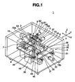
- a spectacle lens edging apparatus denoted by reference numeral 1 is an apparatus to manufacture a spectacle lens 2A ( Fig. 5A ) having a desired edged lens shape by edging a processing target lens 2 formed of an unprocessed round lens, and includes a box-like housing 3 installed on a floor surface.
- a lens rotating shaft 4, a first lens rotating shaft moving mechanism 5, a second lens rotating shaft moving mechanism 6, a processing tool 7, a rotational drive mechanism 8 for the processing tool 7, a controller (not shown), a lens shape measurement unit 9, a chamfering mechanism 10 for the processing target lens 2, and the like are built in the housing 3.
- the processing target lens 2 is mounted on the lens rotating shaft 4 through a lens holding means.
- the first lens rotating shaft moving mechanism 5 moves the lens rotating shaft 4 in an axial direction (X direction).
- the second lens rotating shaft moving mechanism 6 similarly moves the lens rotating shaft 4 in a horizontal direction (Y direction) perpendicular to the axis.
- the processing tool 7 edges the processing target lens 2.
- the controller controls the entire apparatus.
- the lens shape measurement unit 9 measures optical surfaces 2a and 2b of the processing target lens 2.
- the upper surface of the housing 3 is provided with an operation panel (not shown) including a display and various types of operation buttons to input lens information on the processing target lens 2, information on a spectacle frame, processing conditions, and the like.
- the processing target lens 2 is formed of a round (with a diameter of, e.g., 80 mm) plastic minus-power lens formed by casting and polymerization.
- optical base material of the processing target lens 2 examples include, e.g., a copolymer formed from methyl methacrylate and at least another monomer, a copolymer formed from diethylene glycol bis(allyl carbonate) and at least another monomer, and a vinyl copolymer containing polycarbonate, urethane, polystyrene, polyvinyl chloride, unsaturated polyester, polyethylene terephthalate, polyurethane, polythiourethane, sulfide utilizing an enthiol reaction, or sulfur.
- a urethane-based optical base material and an allyl-based optical base material are particularly preferable among these base materials, the present invention is not limited to them.
- the optical base material of the present invention is preferably a plastic optical base material, and more preferably a plastic optical base material for spectacles.
- a protective film layer 64 and water-repellent film layer 67 are stacked on the entire surface of each of the optical surfaces 2a and 2b of the processing target lens 2.
- the protective film layer 64 is formed to improve the optical characteristics, durability, resistance to marring, and the like of the lens, and ordinarily includes a hard coat film layer 65 and antireflection film layer 66.
- the lowermost hard coat film layer 65 is formed to enhance the hardness of the spectacle lens itself and improve the resistance to marring.
- an organic substance such as a silicon-based resin is used.
- the hard coat film layer 65 is formed by applying a silicon-based resin made of a solvent by dipping or spin coating and curing the applied resin by heating in a heating furnace. This method of forming the hard coat film layer 65 is conventionally known well.
- the antireflection film layer 66 as the intermediate layer is formed to enhance the antireflection effect and the resistance to marring.
- the antireflection film layer 66 is formed from a plurality of different materials so it forms a multilayered antireflection film layer.
- an antireflecting material for example, a metal oxide or silicon oxide of Zr, Ti, Sn, Si, In, Al, or the like, or MgF 2 is used.
- Such a multilayered antireflection film layer 66 is formed by vacuum deposition described in, e.g., Japanese Patent Laid-Open No. 11-333685 described above.
- the multilayered antireflection film layer 66 is preferably formed by an ion-assisted deposition method so that it obtains a high film strength and good adhesion.
- the layers that form films other than a hybrid layer of the antireflection film are tantalum oxide (Ta 2 O 5 ) layers serving as high-refractive layers so that physical properties such as a good antireflection effect and resistance to marring can be obtained.
- Each tantalum oxide layer contains preferably at least 50 wt% of tantalum oxide and more preferably 80 wt% or more of tantalum oxide.
- the preferable output range of the acceleration voltage is 50 V to 700 V and that of the acceleration current is 30 mA to 250 mA from the viewpoint of obtaining a particularly good reaction.
- argon (Ar) or a gas mixture of argon and oxygen is preferably used in consideration of the reactivity and oxidation prevention during film formation.
- the inorganic substance used in the hybrid layer of the present invention must include silicon dioxide and can include at least one member selected from the group consisting of aluminum oxide, titanium oxide, zirconium oxide, tantalum oxide, yttrium oxide, and niobium oxide. When using a plurality of inorganic substances, they may be mixed physically. Alternatively, the inorganic substance can be a composite oxide, e.g., silicon dioxide (SiO 2 ) or aluminum monoxide (Al 2 O 3 ). Among them, silicon dioxide alone and at least one type of inorganic oxide selected from the group consisting of silicon dioxide and aluminum oxide are preferable.
- an organic silicide which is liquid at normal temperature and normal pressure and/or an organic compound not containing silicon, which is liquid at normal pressure, is preferable from the viewpoint of film thickness control and deposition rate control.
- the organic silicide preferably has any one of the structures represented by the following general formulas (a) to (d):
- m and n each independently represent an integer of 0 or more.
- X 1 to X 8 each independently represent hydrogen, a hydrocarbon group (including both saturated and unsaturated hydrocarbon groups) having 1 to 6 carbon atoms, an -OR 1 group, a -CH 2 OR 2 group, a -COOR 3 group, an -OCOR 4 group, an -SR 5 group, a -CH 2 SR 6 group, an -NR 7 2 group, or a -CH 2 NR 8 2 group
- R 1 to R 8 each independently represent hydrogen or a hydrocarbon group (including both saturated and unsaturated hydrocarbon groups) having 1 to 6 carbon atoms.
- X 1 to X 8 may be arbitrary ones of the above functional groups and may all be the same or different.
- hydrocarbon group having 1 to 6 carbon atoms represented by R 1 to R 8 include a methyl group, ethyl group, n-propyl group, isopropyl group, n-butyl group, isobutyl group, pentyl group, hexyl group, vinyl group, allyl group, ethynyl group, phenyl group, cyclohexyl group, propenyl group, and isopropenyl group.
- Specific examples of the compound represented by general formula (a) include trimethylsilanol, tetramethylsilane, diethylsilane, dimethylethoxysilane, hydroxymethyltrimethylsilane, methoxytrimethylsilane, dimethoxydimethylsilane, methyltrimethoxysilane, mercaptomethyltrimethoxysilane, tetramethoxysilane, mercaptomethyltrimethylsilane, aminomethyltrimethylsilane, dimethyl(dimethylamino)silane, ethynyltrimethylsilane, diacetoxymethylsilane, allyldimethylsilane, trimethylvinylsilane, methoxydimethylvinylsilane, acetoxytrimethylsilane, trimethoxyvinylsilane, diethylmethylsilane, ethyltrimethylsilane, ethoxytrimethylsilane, diethoxymethylsi
- Specific examples of the compound represented by general formula (b) include 1,1,3,3-tetramethyldisilazane, hexamethyldisilazane, and 1,3-divinyl-1,1,3,3-tetramethyldisilazane.
- Specific examples of the compound represented by general formula (c) include hexamethylcyclotrisiloxane, hexaethylcyclotrisiloxane, 1,3,5,7-tetramethylcyclotetrasiloxane, and octamethylcyclotetrasiloxane.
- Specific examples of the compound represented by general formula (d) include 1,1,3,3,5,5-hexamethylcyclotrisilazane and 1,1,3,3,5,5,7,7-octamethylcyclotetrasilazane.
- the number average molecular weights of these organosilicon compounds fall within the range of preferably 48 to 600 and most preferably 140 to 500 from the viewpoint of control of organic components in hybrid films and the strengths of the films themselves.
- a non-silicon-containing organic compound of the hybrid layer includes preferably a compound containing hydrogen and carbon as indispensable components and having a reactive group at its side chain or terminal, and more specifically a compound represented by general formulas (e) to (g).
- R 9 represents hydrogen or a hydrocarbon group which has 1 to 10 carbon atoms and may contain oxygen
- R 10 represents a divalent hydrocarbon group which has 1 to 7 carbon atoms and may contain oxygen
- X 9 to X 12 each independently represent hydrogen, a hydrocarbon group having 1 to 10 carbon atoms, or an organic group containing hydrogen and carbon having 1 to 10 carbon atoms as indispensable components and at least one of oxygen and nitrogen as an indispensable component.
- Specific examples of the compound represented by general formula (e) include methyl glycidyl ether, butyl glycidyl ether, 2-ethylhexydyl glycidyl ether, decyl glycidyl ether, stearyl glycidyl ether, allyl glycidyl ether, phenyl glycidyl ether, p-sec-butylphenyl glycidyl ether, p-tert-butylphenyl glycidyl ether, 2-methyloctyl glycidyl ether, glycidol, trimethylol, and propane polyglycidyl ether.
- Specific examples of the compound represented by general formula (f) include neopentyl glycol diglycidyl ether, glycerol diglycidyl ether, glycerol triglycidyl ether, propylene glycol diglycidyl ether, tripropylene glycol diglycidyl ether, polypropylene glycol diglycidyl ether, 1,6-hexanediol diglycidyl ether, ethylene glycol diglycidyl ether, diethylene glycol diglycidyl ether, and polyethylene glycol diglycidyl ether.
- general formula (g) examples include ethylene, propylene, vinyl chloride, vinyl fluoride, acrylamide, vinylpyrrolidone, vinylcarbazole, methyl methacrylate, ethyl methacrylate, benzyl methacrylate, n-butyl methacrylate, isobutyl methacrylate, dimethyl amino ethyl methacrylate, mathacrylic acid, glycidyl methacrylate, vinyl acetate, and styrene.
- the number average molecular weights of these compounds represented by general formulas (e) to (g) fall within the range of preferably 28 to 4,000 and most preferably 140 to 360 in consideration of control of organic components in hybrid films and the strengths of the films themselves.
- an organosilicon compound which is liquid at normal temperature and normal pressure and/or a non-silicon-containing organic compound which is liquid at normal temperature and normal pressure
- the external tank which stores an organic material is heated and evacuated, the organic material is supplied to the chamber, and oxygen gas and/or argon gas is used to perform ion-assisted deposition in view of deposition rate control.
- the organic material is liquid at normal temperature and normal pressure.
- the present invention does not need a solvent, and allows direct heating and evaporation of the organic material. It is effective to arrange the supply port of the organic material right above the inorganic material vapor source to improve impact resistance and wear resistance. It is preferable to supply the organosilicon compound upward and supply downward the non-silicon-containing organic compound having a reactive group at its side chain or terminal and containing carbon and hydrogen as indispensable components.
- the heating temperature of the external tank falls within the range of 30 to 200°C and preferably 50 to 150°C to obtain an appropriate deposition rate, depending on the vaporization temperatures of organic materials.
- the content of the organic material in the hybrid layer according to the present invention falls within the range of 0.020 to 25 wt% particularly in consideration of a better physical property improvement effect.
- ⁇ represents the wavelength of light.
- First layer 0.005 ⁇ to 1.25 ⁇ 1.41 to 1.50 Second layer 0.005 ⁇ to 0.10 ⁇ 2.00 to 2.35
- Third layer 0.005 ⁇ to 1.25 ⁇ 1.41 to 1.50 Fourth layer 0.05 ⁇ to 0.45 ⁇ 2.00 to 2.35
- Fifth layer 0.005 ⁇ to 0.15 ⁇ 1.41 to 1.50 Sixth layer 0.05 ⁇ to 0.45 ⁇ 2.00 to 2.35 Seventh layer 0.2 ⁇ to 0.29 ⁇ 1.41 to 1.50
- the above physical properties of the films can achieve the target physical properties.
- the uppermost water-repellent film layer 67 improves the smoothness of the convex optical surface 2a and the concave optical surface 2b to improve the antifouling property and prevent water stain.
- a super water-repellent lens excellent in slide property is recently popular.
- a water-repellent agent made from an organosilicon compound containing a fluorine-substituted alkyl group is used as the water-repellent agent.
- the material and formation method of the water-repellent film layer 67 preferably employ a method described in Japanese Patent Laid-Open No. 2004-122238 .
- the organosilicon compound containing the fluorine-substituted alkyl group diluted with a solvent is set in a reduced pressure.
- the process from the start of heating to the deposition is preferably finished within 90 sec and preferably 10 sec in the temperature range equal to or higher than the deposition start temperature of this organosilicon compound and not exceeding its decomposition temperature.
- a method which achieves this deposition time range is preferably a method which irradiates the organosilicon compound with an electron beam.
- a compound represented by general formula (h) or unit formula (i) is preferably used as the organosilicon compound containing the fluorine-substituted alkyl group.
- RF represents a straight chain perfluoroalkyl group having 1 to 16 carbon atoms
- X represents hydrogen or a lower alkyl group having 1 to 5 carbon atoms
- R 11 represents a hydrolyzable group
- k is an integer of 1 to 50
- r is an integer of 0 to 2
- p is an integer of 1 to 10.
- Examples of the hydrolyzable group represented by R 11 include an amino group, an alkoxy group particularly an alkoxy group including an alkyl part having 1 to 2 carbon atoms, and a chlorine atom.
- the compound represented by unit formula (i) include n-CF 3 CH 2 CH 2 Si(NH 2 ) 3 ; n-trifluoro(1,1,2,2-tetrahydro)propylsilazane, n-C 3 F 7 CH 2 CH 2 Si(NH 2 ) 3 ; n-heptafluoro(1,1,2,2-tetra-hydro)pentylsilazane, n-C 4 F 9 CH 2 CH 2 Si(NH 2 ) 3 ; n-nonafluoro(1,1,2,2-tetrahydro)hexylsilazane, n-C 6 F 13 CH 2 CH 2 Si 2 (NH 2 ) 3 ; n-trideofluoro (1,1,2,2-tetra-hydro) octylsilazane, and n-C 8 F 17 CH 2 CH 2 Si(NH 2 ) 3 ; n-heptadecafluoro(1,1,2,2-tetrahydro)
- the material of the water-repellent film layer 67 may contain as two major components the organosilicon compound containing the fluorine-substituted alkyl group and perfluoropolyeter not containing silicon.
- a first layer may be formed from these major components, and a second layer may be formed on the first layer using a material containing as a major component perfluoropolyether not containing silicon, thereby forming the water-repellent film layer.
- the perfluoropolyether not containing silicon preferably employs a compound consisting of a unit having the following structural formula: -(R 12 O)- (j)
- R 12 represents a perfluoroalkylene group having 1 to 3 carbon atoms. The average molecular weight falls within the range of 1,000 to 10,000 and more preferably 2,000 to 10,000.
- R represents a perfluoroalkylene group having 1 to 3 carbon atoms, and its specific examples include groups such as CF 2 , CF 2 -CF 2 , CF 2 CF 2 CF 2 , and CF(CF 2 )CF 2 .
- These perfluoropolyethers are liquid at normal temperature and called fluorine oils.
- a layer made from at least one metal selected from metals having a catalyst function in forming a hybrid layer can be formed as an underlayer below an antireflection film layer in order to improve the bonding property.
- the most preferable underlayer is a metal layer made from niobium to impart better impact resistance. Use of the metal layer as the underlayer enhances the reaction with the hybrid layer formed on the underlayer, thereby obtaining a material having an intra-molecular network structure and improving the impact resistance.
- a double layer structure inside the uppermost water-repellent film layer 67, i.e., the first and second water-repellent layers.
- a vapor material containing a mixture of the organosilicon compound containing the fluorine-substituted alkyl group represented by general formula (I) and at least one silane compound selected from the following general formulas (II-1), (II-2), and (II-3) is deposited on the optical member to form the first water-repellent layer.
- the resultant structure is dipped in a dipping material containing a solvent and perfluoropolyether-polysiloxane copolymer modified silane represented by general formula (III) to form the second water-repellent layer, thereby forming a water-repellent film layer 67 made from the two layers.
- a dipping material containing a solvent and perfluoropolyether-polysiloxane copolymer modified silane represented by general formula (III) to form the second water-repellent layer, thereby forming a water-repellent film layer 67 made from the two layers.
- Rf represents a divalent group which includes a unit represented by formula -(C k F 2k O)- (wherein k is an integer of 1 to 6) and has an unbranched straight chain perfluoropolyalkylene ether structure.
- R independently represents a monovalent hydrocarbon group having 1 to 8 carbon atoms.
- X independently represents a hydrolyzable group or halogen atom, n and n' each represent an integer of 0 to 2, m and m' each represent an integer of 1 to 5, and a and b each represent 2 or 3.
- Rg represents a divalent group which includes a repeating unit represented by formula -(C j F 2j O)- (wherein j is an integer of 1 to 5) and has an unbranched straight chain perfluoropolyalkylene ether structure.
- the repeating unit count is 30 to 60. Different j repeating units may be simultaneously included.
- R 1 represents the same or different alkyl groups or phenyl groups having 1 to 4 carbon atoms, w is 30 to 100, and a , b, and c each independently represent an integer of 1 to 5.
- R 2 represents an alkyl group or phenyl group having 1 to 4 carbon atoms
- X 1 represents a hydrolyzable group
- d is 2 or 3
- y is an integer of 1 to 5.
- the Rf group is a divalent group which includes a unit represented by formula -(C k F 2k O)- (wherein k is an integer of 1 to 6 and preferably 1 to 4, and the sequence of CkF 2k O in general formula (I) is random) and has an unbranched straight chain perfluoropolyalkylene ether structure. Note that when both n and n' in general formula (I) are zero, the terminal of the Rf group bonded to the oxygen atom (O) in general formula (I) is not an oxygen atom:
- Rf represents a divalent straight chain perfluoropolyether group and include perfluoropolyether groups having a variety of chain lengths.
- Rf preferably represents a divalent straight chain perfluoropolyether having a perfluoropolyether having 1 to 6 carbon atoms as the repeating unit.
- this divalent straight chain perfluoropolyether are as follows: -CF 2 CF 2 O(CF 2 CF 2 CF 2 O) r CF 2 CF 2- -CF 2 (OC 2 F 4 ) 5 -(OCF 2 ) t - wherein r, s, and t each represent an integer of 1 or more. More specifically, r, s, and t each fall within the range of 1 to 50 and more preferably 10 to 40.
- the perfluoropolyether molecular structure is not limited to the exemplified structures.
- X represents a hydrolyzable group or halogen atom.
- X as the hydrolyzable group include an alkoxy group such as a methoxy group, ethoxy group, propoxy group, or butoxy group; an alkoxyalkoxy group such as a methoxymethoxy group, methoxyethoxy group, or ethoxyethoxy group; an alkenyloxy group such as an allyloxy group or isopropenoxy group; an asiloxy group such as an acetoxy group, propyonyloxy group, butylcarbonyloxy group, or benzoyloxy group; a ketoxime group such as a dimethylketoxime group, methylethylketoxime group, diethylketoxime group, cyclopentanoxime group, or cyclohexanoxime group; an amino group such as an N-methylamino group, N-ethylamino group, N-propylamino group, N
- Examples of X as the halogen atom include a chlorine atom, bromine atom, and iodine atom. Among them all, the methoxy group, ethoxy group, isopropenoxy group, and chlorine atom are most preferable.
- R represents a monovalent hydrocarbon group having 1 to 8 carbon atoms. If R represents a plurality of monovalent hydrogen groups, they may be the same or different. Specific examples of R include an alkyl group such as a methyl group, ethyl group, propyl group, butyl group, pentyl group, hexyl group, heptyl group, or octyl group; a cycloalkyl group such as a cyclopentyl group or cyclohexyl group; an aryl group such as a phenyl group, tolyl group, or xylyl group; an aralkyl group such as a benzyl group or phenetyl group; and an alkenyl group such as a vinyl group, allyl group, butenyl group, pentenyl group, or hexenyl group. Among them all, a monovalent hydrocarbon group having 1 to 3 carbon atoms is preferable
- n and n' each represent an integer of 0 to 2 and preferably 1, and may be the same or different
- m and m' each represent an integer of 1 to 5, preferably 3, and may be the same or different.
- a and b each represent 2 or 3 and preferably 3 in view of hydrolysis, condensation reactivity, and bonding property.
- the molecular weight of the organosilicon compound containing the fluorine-substituted alkyl group represented by general formula (I) is not particularly limited, but its number average molecular weight appropriately falls within the range of 500 to 20,000 and preferably 1,000 to 10,000 in view of stability and handling.
- organosilicon compound containing the fluorine-substituted alkyl group represented by structural formula (I) are as follows, but are not limited to the exemplified compounds.
- the compound represented by general formula (I) can be used singly or in a combination of two or more compounds.
- the organosilicon compound containing the fluorine-substituted alkyl group and its partial hydrolyzed condensate can be combined and used.
- perfluoropolyether-polysiloxane copolymer modified silane represented by general formula (III) can be combined and used with the compound represented by general formula (I).
- the organosilicon compound containing the fluorine-substituted alkyl group represented by general formula (I) is preferably diluted with a solvent.
- a solvent to be used include a fluorine-modified aliphatic hydrocarbon solvent (e.g., perfluoroheptane or perfluorooctane), a fluorine-modified aromatic hydrocarbon solvent (e.g., 1,3-di(trifluoromethyl)benzene or trifluoromethylbenzene), a fluorine-modified ether solvent (e.g., methylperfluorobutyl ether or perfluoro(2-butyltetrahydrofurane), a fluorine-modified alkylamine solvent (e.g., perfluorotributylamine or perfluorotripentylamine), a hydrocarbon solvent (e.g., petroleum benzene, mineral spirits, toluene, or xylene), a ketone
- solvents can be used singly or in a combination of two or more solvents.
- a fluorine-modified solvent is preferable in view of the dissolvability and wettability of modified silane.
- the most preferable solvent include 1,3-di(trifluoromethyl)benzene, perfluoro(2-butyltetrahydrofurane), and perfluorotributylamine.
- silane compound selected from the general formulas (II-1), (II-2), and (II-3) comprises the following: General formula (II-1) R'-Si(OR") 3 General formula (II-2) Si(OR") 4 General formula (II-3) SiO(OR") 3 3Si(OR") 3
- R' represents an organic group.
- R' include an alkyl group (e.g., a methyl group, ethyl group, or propyl group) having 1 to 50 carbon atoms (preferably 1 to 10 carbon atoms), an epoxyethyl group, a glycidyl group, and an amino group. These groups may be substituted.
- R" represents an alkyl group (e.g., a methyl group, ethyl group, or propyl group) having 1 to 48 carbon atoms and is preferably a methyl group or ethyl group.
- silane compounds represented by general formulas (II-1) to (II-3) include structural formulas (C 2 H 5 O) 3 SiC 3 H 6 NH 2 , (CH 3 O) 3 SiC 3 H 6 NH 2 , (C 2 H 5 O) 4 Si, and (C 2 H 5 O) 3 Si-O-Si(OC 2 H 5 ) 3 .
- the silane compound is not limited to the above examples.
- silane compounds represented by general formulas (II-1) to (II-3) can be used singly or in a combination of two or more silane compounds.
- the silane compound preferably contains the compound represented by general formula (II-1) singly or in an amount larger than those of other components.
- the Rg group is a divalent group which includes repeating unit represented by formula -(C j F 2j O)- (wherein j is an integer of 1 to 5 and preferably 1 to 3, and the sequence of C j F 2j O in general formula (III) is random) and has an unbranched straight chain perfuluoropolyalkylene ether structure.
- the repeating unit count is 30 to 60 (preferably 30 to 50). Different j repetition counts may be simultaneously included:
- Rg represents a divalent straight chain perfluoropolyether group and include perfluoropolyether groups having a variety of chain lengths.
- Rg preferably represents a divalent straight chain perfluoropolyether having a perfluoropolyether having about 1 to 5 carbon atoms as the repeating unit.
- this divalent straight chain perfluoropolyether are as follows: -CF 2 CF 2 O(CF 2 CFCF 2 O) k CF 2 CF 2 - -CF 2 (OC 2 F 4 ) p -(OCF 2 ) q - wherein k, p, and q each represent an integer of 1 or more, and k and p+q preferably fall within the range of 30 to 60.
- the perfluoropolyether molecular structure is not limited to the exemplified structures.
- R 1 represents an alkyl group (e.g., a methyl group, ethyl group, propyl group, or butyl group) or phenyl group having 1 to 4 carbon atoms.
- the alkyl groups or phenyl groups may be the same or different.
- w is 30 to 100 and preferably 30 to 60
- a , b, and c each independently represent an integer of 1 to 5 and preferably 1 to 3.
- R 2 represents an alkyl group (e.g., a methyl group, ethyl group, propyl group, or butyl group) or phenyl group having 1 to 4 carbon atoms.
- X 1 represents a hydrolyzable group.
- X 1 include an alkoxy group such as a methoxy group, ethoxy group, propoxy group, or butoxy group; an alkoxyalkoxy group such as a methoxymethoxy group, methoxyethoxy group, or ethoxyethoxy group; alkenyloxy group such as an allyloxy group or isopropenoxy group; an acyloxy group such as an acetoxy group, propionyloxy group, butylcarbonyloxy group, or benzoyloxy group; a ketoxime group such as a dimethylketoxime group, methylethylketoxime group, diethylketoxime group, cyclopentanoxime group, or cyclohexanoxime group; an amino group such as an N-methylamino group, N-ethylamino group, N-propylamino group, N-butylamino group, N,N-
- d is 2 or 3 and preferably 3 in consideration of hydrolysis, condensation reactivity, and film bonding property
- y is an integer of 1 to 5 and preferably 1 to 3.
- the compounds represented by general formula (III) can be used singly or in a combination of two or more compounds.
- the material of the plastic base member used in the present invention is not limited to a specific material.
- the plastic base member include a methyl methacrylate homopolymer, a copolymer formed from methyl methacrylate and at least another monomer, a homopolymer made from diethylene glycol bisallylcarbonate, a copolymer formed from diethylene glycol bis(allyl carbonate) and at least another monomer, a sulfur-containing copolymer, a halogen copolymer, and a polymer using as a material a compound including polycarbonate, polystyrene, polyvinyl chloride, unsaturated polyester, polyethylene terephtalate, polyurethane, polythiourethane, or epithio group.
- Examples of the compound having the epithio group include chain organic compounds such as bis( ⁇ -epithiopropylthio)metane, 1,2-bis( ⁇ -epithiopropylthio)ethane, 1,3-bis( ⁇ -epithiopropylthio)propane, 1-2-( ⁇ -epithiopropylthio)propane, 1-( ⁇ -epithiopropylthio)-2-( ⁇ -epithiopropylthio)propane, 1,4-bis( ⁇ -epithiopropylthio)butane, 1,3-bis( ⁇ -epithiopropylthio)butane, 1-( ⁇ -epithiopropylthio)-3-( ⁇ -epithiopropylthiomethyl)butane, 1,5-bis( ⁇ -epithiopropylthio)pentane, 1-( ⁇ -epithiopropylthio)-4-(
- Examples of the compound having the epithio group also include branched organic compounds and compounds obtained by substituting at least one hydrogen of the episulfide group of each of these compounds with a methyl group.
- Specific examples of the branched organic compounds include tetrakis( ⁇ -epithiopropylthiomethyl)methane, 1,1,1-tris( ⁇ -epithiopropylthiomethyl)propane, 1,5-bis( ⁇ -epithiopropylthio)-2-( ⁇ -epithiopropylthiomethyl)-3-thiapentane, 1,5-bis( ⁇ -epithiopropylthio)-2,4-bis( ⁇ -epithiopropylthiomethyl)-3-thiopentane, 1-( ⁇ -epithiopropylthio)-2,2-bis( ⁇ -epithiopropylthiomethyl)-4-thiahexane, 1,5,6-tris( ⁇ -epithio
- Examples of the compound having the epithio group further include alicyclic organic compounds and compounds obtained by substituting at least one hydrogen of the episulfide group of each of these compounds with a methyl group, and aromatic organic compounds and compounds obtained by substituting at least one hydrogen of the episulfide group of each of these compounds with a methyl group.
- alicyclic organic compound examples include 1,3- and 1,4-bis( ⁇ -epithiopropylthio)cyclohexane, 1,3- and 1,4-bis( ⁇ -epithiopropylthiomethyl)cyclohexane, bis[4-( ⁇ -epithiopropylthio)cyclohexyl]methane, 2,2-bis[4-( ⁇ -epithiopropylthio)cyclohexyl]propane, bis[4-( ⁇ -epithiopropylthio)cyclohexyl]sulfide, 2,5-bis( ⁇ -epithiopropylthiomethyl)-1,4-dithiane, and 2,5-bis( ⁇ -epithiopropylthioethylthiomethyl)-1,4-dithiane.
- aromatic organic compound examples include 1,3- and 1,4-bis( ⁇ -epithiopropylthio)benzene, 1,3- and 1,4-bis( ⁇ -epithiopropylthiomethyl)benzene, bis[4-( ⁇ -epithiopropylthio)phenyl]methane, 2,2-bis[4-( ⁇ -epithiopropylthio)phenyl]propane, bis[4-( ⁇ -epithiopropylthio)phenyl]sulfide, bis[4-( ⁇ -epithiopropylthio)phenyl)sulfone, and 4,4'-bis( ⁇ -epithiopropylthio)biphenyl.
- the lens rotating shaft 4 includes first and second lens rotating shafts 4A and 4B arranged horizontally such that their axes coincide with each other, and is disposed in a lens holding unit 15.
- the lens holding unit 15 has a pair of supports 15a and 15b opposing each other in the horizontal direction (X direction) of the apparatus.
- One support 15a axially, rotatably supports the first lens rotating shaft 4A, and the other support 15b axially supports the second lens rotating shaft 4B to be rotatable and movable in the axial direction.
- a lens holder 16 and lens retainer 17 constituting the lens holding means for the processing target lens 2 are detachably attached to the opposing distal ends of the first and second lens rotating shafts 4A and 4B, respectively.
- a lens rotating shaft driving motor 18 is fixed to the other support 15b of the lens holding unit 15.
- the rotation of the driving motor 18 is transmitted to the first and second lens rotating shafts 4A and 4B through a rotation transmitting means 19 such as a pulley or toothed belt. Therefore, the first and second lens rotating shafts 4A and 4B are synchronously driven.
- a reversible pulse motor with a variable rotation speed is used as the lens rotating shaft driving motor 18.
- a driving motor (not shown) which moves the second lens rotating shaft 4B forward/backward with respect to the first lens rotating shaft 4A is built in the other support 15b of the lens holding unit 15.
- the first lens rotating shaft moving mechanism 5 includes a pair of front and rear X-axis linear guides 31, an X-direction table 32, and an X-direction table driving motor 33.
- the X-axis linear guides 31 are set on a bottom plate 30 of the housing 3 to be parallel to each other and are long in the X direction.
- the X-direction table 32 is movable in the X direction along the X-axis linear guides 31.
- the X-direction table driving motor 33 moves the X-direction table 32 along the X-axis linear guides 31.
- the second lens rotating shaft moving mechanism 6 includes a pair of left and right Y-axis linear guides 35, a Y-direction table 36, a Y-direction table driving motor 37, and the lens holding unit 15.
- the Y-axis linear guides 35 are set on the upper surface of the X-direction table 32 to be parallel to each other and extend in the Y direction.
- the Y-direction table 36 is movable in the Y direction along the Y-axis linear guides 35.
- the Y-direction table driving motor 37 moves the Y-direction table 36 along the Y-axis linear guides 35.
- the lens holding unit 15 is set on the Y-direction table 36.
- the operation of the lens rotating shaft 4 includes movements in three directions, i.e., rotation about the axis, movement in the horizontal direction (X direction) perpendicular to the axis, and movement in the back-and-forth direction (Y direction).
- the controller numerically controls the movements in the three directions based on the shape processing data on the processing target lens 2.
- the processing tool 7 As the processing tool 7 which grinds a circumferential surface 2c of the processing target lens 2, a grinding stone such as a cylindrical diamond wheel as shown in Fig. 2 is employed and attached to a processing tool rotating shaft 40 of the rotational drive mechanism 8.
- the processing tool 7 includes a primary processing (rough processing) grinding wheel 7A and secondary processing (finishing) grinding wheel 7B.
- a beveling groove 41 formed of an axi-symmetric V-shaped annular groove is formed in the outer circumferential surface of the secondary processing grinding wheel 7B.
- the rotational drive mechanism 8 of the processing tool 7 includes a frame 44, the processing tool rotating shaft 40, an inverter type processing tool driving motor 45, and a rotation transmitting mechanism 46 such as a pulley or toothed belt.
- the frame 44 is set on the bottom plate 30 of the housing 3.
- the processing tool rotating shaft 40 is cantilevered at the upper end of the frame 44.
- the processing tool driving motor 45 rotates the processing tool rotating shaft 40.
- the rotation transmitting mechanism 46 transmits the rotation of the processing tool driving motor 45 to the processing tool rotating shaft 40.
- the processing tool rotating shaft 40 is parallel to the lens rotating shaft 4 and located in front of it.
- the lens shape measurement unit 9 includes a pair of left and right measurement elements 50A and 50B, a driving motor (not shown), and an arithmetic processing unit (not shown).
- the measurement elements 50A and 50B are disposed to oppose each other and trace the optical surfaces 2a and 2b of the processing target lens 2.
- the driving motor moves the measurement elements 50A and 50B to be close to and separate from each other.
- the arithmetic processing unit calculates the positions of the optical surfaces 2a and 2b and those of the two edges of each of the circumferential surface 2c and circumferential surfaces 2d and 2e, i.e., convex peripheral edges 51A, 52A, and 53A and concave peripheral edges 51B, 52B, and 53B, of the processing target lens 2 from the traces of the measurement elements 50A and 50B, and measures shape information on the processing target lens 2.
- reference numeral 2c denotes the circumferential surface of the processing target lens 2 before edging; 2d, the circumferential surface after primary processing; and 2d, the circumferential surface after secondary processing.
- the processing target lens 2 When measuring the shape of the processing target lens 2 by the lens shape measurement unit 9, the processing target lens 2 is rotated. The left and right measurement elements 50A and 50B are moved close to each other and urged against the optical surfaces 2a and 2b, respectively, of the processing target lens 2. In this state, the lens holding unit 15 is moved back and forth. Then, the shape of the processing target lens 2 can be measured.
- the chamfering mechanism 10 chamfers the edge portions 53A and 53B of the processing target lens 2 after secondary processing, and includes a pair of left and right chamfering tools 60, a chamfering driving motor 61, and a rotation transmitting mechanism 62 such as a pulley or belt.
- the chamfering driving motor 61 drives the chamfering tools 60.
- the rotation transmitting mechanism 62 transmits the rotation of the chamfering driving motor 61 to the chamfering tools 60.
- grinding tools such as diamond wheels are employed.
- the optician as the order placing side transmits information on a spectacle lens needed by the manufacturer to the lens manufacturer's factory as the manufacturing side in an online manner (step S1).
- the optician sends to the factory various types of information such as the material and prescription values of the lens, the specified processing values of the lens, spectacle frame information, layout information which specifies the eye point position, the bevel mode, the bevel position, and the bevel shape that are necessary for the lens manufacture.
- the spectacle frame information includes 3-dimensional lens frame shape data, approximate curved surface definition data, a frame PD (or DBL), an optical axis angle, and the circumferential length.
- This request for manufacturing the spectacle lens from the optician to the factory is effective particularly when, e.g., requesting the manufacture of a lens having a water-repellent film layer (because primary processing by the optician is difficult if a water-repellent film layer is formed on the lens).
- processing shape data At the factory, upon acquiring various types of information necessary for the manufacture of the spectacle lens from the optician, processing shape data, edged lens shape information, layout information, processing designation information and the like are created based on the acquired information, and input to the edging apparatus 1 (step S2).
- the operator selects among uncut lenses stored as the stock a lens complying with the ordered lens as the processing target lens 2 and holds the optical surface 2a of the selected lens 2 using the lens holder 16 (step S3).
- the lens holder 16 includes a metal shaft portion 70 and a holding cup 71 which is integrally molded with the shaft portion 70 and made of an elastic material.
- the holding cup 71 includes a shaft portion 71A fixed to the shaft portion 70 and a lens holding portion 71B integrally provided to the distal end face of the shaft portion 71A.
- the lens holding portion 71B forms a rectangular plate.
- the front surface of the lens holding portion 71B forms a lens holding surface 72.
- the lens holding surface 72 forms a concave surface with a radius of curvature almost equal to that of the convex optical surface 2a of the lens 2.
- a leap tape 73 is adhered to the lens holding surface 72.
- the leap tape 73 may be adhered to the convex optical surface 2a by urging.
- the lens holder 16 is attached to the processing target lens 2 such that its center O coincides with a processing center position 21 serving as the rotation center of the processing target lens 2 when processing the processing target lens 2, as shown in Fig. 5A .
- the lens holder 16 is attached to the lens by setting the cylinder axis at a predetermined angle.
- the processing center position 21 of the processing target lens 2 coincides with a frame center B of the spectacle frame, or an optical center C of the processing target lens 2.
- the operator displays two axial deviation measuring marks 81a and 81b ( Figs. 5A to 5C ) on the convex optical surface 2a of the processing target lens 2 (step S4).
- Two reference position marks 80a and 80b are displayed on the lens holder 16 in advance, and the axial deviation measuring marks 81a and 81b are displayed to coincide with the marks 80a and 80b.
- the reference position marks 80a and 80b of the lens holder 16 include two perpendicular straight lines extending through the center O and are displayed on the rear surface of the lens holding portion 71B.
- the reference position marks 80a and 80b are displayed on the lens holder 16 in advance before the processing target lens 2 is held.
- the reference position marks 80a and 80b and axial deviation measuring marks 81a and 81b may be simultaneously displayed on the lens holder 16 and processing target lens 2 after the processing target lens 2 is held.
- the axial deviation measuring marks 81a and 81b of the processing target lens 2 include two perpendicular straight lines extending through the processing center position 21. After the lens holder 16 holds the lens 2, the axial deviation measuring marks 81a and 81b are displayed using an appropriate ink such that they form straight lines continuous with the reference position marks 80a and 80b.
- the marks 81a and 81b have different line widths. One mark 81a has a larger line width than that of the other mark 81b.
- the processing target lens 2 is mounted on the lens rotating shaft 4 (step S5).
- the lens holder 16 which holds the processing target lens 2 is mounted on the first lens rotating shaft 4A.
- the lens holder 16 can be mounted by fitting the shaft portion 70 in a recess formed in the distal end face of the first lens rotating shaft 4A.
- the second lens rotating shaft 4B is moved forward to urge the lens retainer 17 attached to the distal end of the lens rotating shaft against the concave optical surface 2b of the processing target lens 2 through an elastic member 85 ( Fig. 2 ).
- the lens holder 16 and lens retainer 17 sandwich and hold the processing center positions 21 of the convex and concave optical surfaces 2a and 2b of the processing target lens 2, thus completely mounting the lens on the lens rotating shaft 4.
- the lens rotating shaft 4 is rotated at a low speed, and the circumferential surface 2c of the processing target lens 2 undergoes primary processing by the processing tool 7 based on the processing shape data (step S6).
- the primary processing grinding wheel 7A grinds the circumferential surface 2c to form the processing target lens 2 into a primary shape.
- the primary shape of the processing target lens 2 obtained by primary processing is either a circle larger than a circle inscribed by the edged lens shape 2A ( Figs. 5A to 5C ) that complies with the frame shape of the spectacle frame, or an edged shape similar to the edged lens shape 2A and larger than it by the processing margin of secondary processing.
- a circle 88 larger than the circle inscribed by the edged lens shape 2A is a circle having a radius (e.g., 50 mm) equal to or slightly larger than a value obtained by adding the processing margin of secondary processing to a maximum radius R ( Fig. 5B ) of the edged lens shape 2A.
- step S7 When primary processing of the processing target lens 2 is ended, the operator removes it from the lens rotating shaft 4 and measures its axial deviation (step S7). Assume that the processing target lens 2 has a water-repellent film layer. If the processing target lens 2 undergoes primary processing while it is held by a lens holding force almost equal to that for a general lens, as the processing resistance is large, axial deviation occurs easily. If secondary processing is performed with the axial deviation uncorrected, the lens becomes defective.
- the lens holder 16 is removed from the first lens rotating shaft 4A, and whether axial deviation exists or not is checked from the reference position marks 80a and 80b and axial deviation measuring marks 81a and 81b.
- Fig. 5B shows a case in which, as the result of primary processing, the processing center position 21 axially deviates from the center O of the lens holder 16 by -X 1 in the X direction and by -Y 1 in the Y direction and the rotation angle axially deviates counterclockwise by - ⁇ 1 with respect to the reference position mark 80a.
- Fig. 5C shows a case in which the processing center position 21 does not axially deviate with respect to the center O of the lens holder 16 and only the rotation angle axially deviates counterclockwise by ⁇ 2 with respect to the reference position mark 80a.
- the deviation amounts X 1 and Y 1 in the X and Y directions of the processing center position 21 with respect to the center O of the lens holder 16, and the rotation angle ⁇ 1 or ⁇ 2 are measured.
- the deviation amounts of the processing center position 21 in the X and Y directions are ⁇ 0.5 mm or more, or if the rotation angle is ⁇ 5° or more, it is determined that the processing center position 21 axially deviates. Otherwise, it is determined that axial deviation does not exist.
- the allowable values of the axial deviation amounts and rotation angle differ depending on the type and dioptric power of the lens. For example, when the target lens is a single-vision lens having a cylinder axis, if the deviation of the rotation angle described above is ⁇ 2° or less, the specifications of the spectacle lens may be satisfied. The tolerance is accordingly selected appropriately.
- This axial deviation measurement is performed by the operator visually, or by known image processing. When image processing is employed, it is advantageous because the deviation amount can be measured more accurately than by visual measurement. Correction of processing shape data by means of image processing will further be described later.
- the processing target lens 2 is held again by the lens holder 16, and the axial deviation is corrected (in step S8). More specifically, the lens holder 16 is removed from the processing target lens 2. The lens holder 16 is then mounted again on the processing target lens 2 such that the center O of the lens holder 16 coincides with the processing center position 21 of the processing target lens 2 and that the reference position marks 80a and 80b coincide with the axial deviation measuring marks 81a and 81b. This corrects the axial deviation. If the axial deviation is equal to or less than the allowable value, the lens holder 16 need not be removed from the processing target lens 2.
- processing target lens 2 is mounted on the lens rotating shaft 4 again in accordance with the same procedure as in step S5 described above (step S9).
- the secondary shape of the processing target lens 2 by secondary processing is an edged lens shape that complies with the edged lens shape 2A of the spectacle frame, or an edged lens shape slightly larger than this.
- the edged lens shape slightly larger than that of the spectacle frame is aimed at reserving, based on the order from the optician, a processing margin necessary when the optician performs finishing.
- the secondary shape of the processing target lens by secondary processing is calculated in advance in the same manner as the primary shape and input to the controller as processing shape data.
- This embodiment employs the grinding wheel 7B having the beveling groove 41, because it is aimed at the manufacture of a spectacle lens to be mounted on a general rimmed spectacle frame.
- the circumferential surface of the processing target lens 2 may be edged by exchanging the grinding wheel 7B for a grinding wheel for a rimless spectacle frame or nylol frame.
- the processing target lens 2 is removed from the lens rotating shaft 4, and its axial deviation is measured (step S11).
- the axial deviation is determined in accordance with whether or not the reference position marks 80a and 80b deviate from the axial deviation measuring marks 81a and 81b in the same manner as in step S7 described above.
- the processing target lens 2 which has undergone primary processing and thus has a small diameter is to be processed. Therefore, even if the lens has a low processing resistance and is formed with a water-repellent film layer, axial deviation rarely occurs, or can be suppressed within the predetermined allowable value range. Thus, highly accurate processing can be performed.
- the operator visually confirms that the axial deviation measuring marks 81a and 81b do not deviate from the reference position marks 80a and 80b, it can guarantee that the processing target lens 2 is free from axial deviation.
- chamfering is performed (step S12).
- Chamfering is performed by rotating the processing target lens 2 together with the lens rotating shaft 4 and urging the chamfering tools 60 against the edge portions 53A and 53B of the circumferential surface 2e.
- the chamfering trace data of the chamfering tools 60 which are used as the control data of the chamfering tools 60 during chamfering are calculated based on position data of the edge portions 53A and 53B of the circumferential surface 2e of the processing target lens 2 which are calculated after secondary processing.
- a processing target lens 2 determined as an acceptable product is packaged as a spectacle lens and delivered to the optician who placed the order (step S14).
- the optician Upon reception of the spectacle lens from the factory, the optician tests its optical performance and appearance. When the optician determines that the spectacle lens is appropriate, if the spectacle lens has an edged lens shape complying with the frame shape of the spectacle frame selected by the user, the optician fits the lens in the spectacle frame and delivers the spectacle frame to the user. If the spectacle lens has an edged lens shape slightly larger than the frame shape of the spectacle frame, the optician finishes the lens so as to comply with the frame shape of the spectacle lens and fits it in the spectacle frame, and delivers the spectacle frame to the user. In finishing by the optician, since the shape of the lens itself is small and accordingly the processing resistance is low, even if the lens is formed with a water-repellent film layer, the lens rarely deviates axially.
- the step of correcting the axial deviation of the processing target lens includes the axial deviation measuring step of removing the processing target lens from the lens rotating shaft together with the lens holding means after primary processing and measuring the axial deviation of the processing target lens from the reference position mark and the axial deviation measuring mark, the axial deviation correcting step of correcting the axial deviation of the processing target lens which is measured by the axial deviation measuring step by holding one optical surface of the processing target lens with the lens holding means again such that the axial deviation measuring mark coincides with the reference position mark, and the step of mounting the lens holding means on the lens rotating shaft again together with the processing target lens.
- the lens can be processed without causing axial deviation, in the same manner as a general lens.
- this embodiment allows axial deviation of the processing target lens 2 in primary processing. If the processing target lens 2 axially deviates due to primary processing, the amount and direction of the axial deviation are measured, and the axial deviation is corrected by holding the processing target lens 2 again by the lens holder 16.
- the axial deviation of the processing target lens 2 is corrected in this manner in secondary processing, since the shape of the lens itself in secondary processing is small, even when the lens has a water-repellent film layer, the axial deviation amount can be suppressed within the allowable value range without holding the lens with a particularly large lens holding force.
- the processing target lens 2 is a highly lubricant lens or an uncut lens having a large diameter in primary processing, no particular axial deviation preventive countermeasure is needed in the primary processing step.
- Such a lens can be processed highly accurately without causing axial deviation in the same manner as a general lens, even if the lens is not held with a particularly large lens holding force.
- Fig. 8 is a flowchart showing another embodiment of the present invention. This embodiment is different from the embodiment described above in terms of how axial deviation is corrected. More specifically, according to the measurement and correction of axial deviation in this embodiment (step S27), axial deviation is measured by image processing, and the processing shape data itself of an edging apparatus 1 is corrected.
- a line sensor 90 is arranged on a straight line extending through a center O of a lens holder 16, as shown in Fig. 9 .
- At least two reference position marks 80a and 80b and axial deviation measuring marks 81a and 81b having different line widths are displayed on the lens holder 16 and a processing target lens 2 in advance to coincide with each other.
- the layout of the optical center (C) on the processing target lens 2 in the mounted state can be discriminated in the vertical and horizontal directions and the like.
- the processing target lens 2 is removed from a lens rotating shaft 4 together with the lens holder 16, and the line sensor 90 obtains the images of the reference position marks 80a and 80b and axial deviation measuring marks 81a and 81b.
- the coordinate values of the reference position marks 80a and 80b and axial deviation measuring marks 81a and 81b are read by rotating the processing target lens 2 in the direction of the arrow. If the marks deviate, the deviation amounts are calculated; if do not, the processing target lens 2 is mounted on the lens rotating shaft 4 again and undergoes secondary processing.
- the reference position is determined on the center O of the lens holder 16 of a case in which the marks do not deviate.
- the reference position is determined on a position where straight lines extending from the two reference position marks 80a and 80b of the lens holder 16 intersect.
- the coordinate values of a point 21' where the straight lines extending from the axial deviation measuring marks 81a and 81b on the processing target lens 2 intersect are calculated, and the processing center position on the processing target lens 2 resulted from the axial deviation is specified (to be referred to as the processing center position 21' hereinafter).
- the distance and direction to the processing center position 21' with reference to the center O of the lens holder 16 are calculated and determined as a correction value A (X, Y).
- the processing center position of the edging apparatus 1 expressed by the correction value A is determined as the processing center 21' on the processing target lens 2 deviating from the center O of the lens holder 16.
- angles formed by the respective axial deviation measuring marks 81a and 81b and reference position marks 80a and 80b are calculated and determined as a correction value B.
- the processing center of the processing shape data is corrected based on the correction value A and correction value B, and secondary processing is performed.
- Steps S21 to S26 and steps S28 to S33 are completely the same as steps S1 to S6 and steps S9 to S14 shown in Fig. 7 , and a repetitive description thereof will be omitted.
- the step of correcting the axial deviation of the processing target lens comprises the step of removing the processing target lens from the lens rotating shaft together with the lens holding means after primary processing, measuring the axial deviation of the processing target lens from the reference position mark and the axial deviation measuring mark, and correcting the processing shape data.
- the processing target lens is processed based on the processing shape data corrected by the processing shape data correcting step. That is, the processing shape data itself is corrected in accordance with the measured axial deviation amount and its direction. Therefore, even when the processing target lens axially deviates from the lens holding means, the lens need not be removed from the lens holding means and held again by it, and can undergo secondary processing in the axially deviating state. As a result, the step of holding the lens again by the lens holding means to correct axial deviation is not needed, and the time needed for lens edging can be shortened.
- the primary shape of the processing target lens processed by the primary processing step is either one of a circle larger than a circle inscribed by the edged lens shape that complies with the frame shape of the spectacle frame and an edged shape similar to this edged lens shape and larger than this.
- the secondary shape of the processing target lens processed by the secondary processing step is either one of an edged lens shape that complies with the frame shape of the spectacle frame and an edged lens shape slightly larger than that.
- the axial deviation measuring step can be performed by either one of image processing and visual measurement.
- the reference position mark can be displayed either before holding the processing target lens or simultaneously with displaying the axial deviation measuring mark on the unprocessed lens.
- the processing target lens is delivered to the optician after it undergoes secondary processing into an edged lens shape complying with the frame shape of the spectacle frame selected by the user, or into an edged lens shape slightly larger than the frame shape.
- a processing target lens having a primary shape which has undergone only primary processing, may be delivered.
- the optician is informed of the axial deviation amount and its direction in addition to the processing center position 21'.
- the optician finishes the processing target lens into a shape complying with the frame shape of the spectacle frame by holding the processing center position 21, and fits the processed lens into the spectacle frame, thus completing a spectacle.
- the edging method according to the present invention is usefully employed in edging a spectacle lens.
Landscapes
- Engineering & Computer Science (AREA)
- Mechanical Engineering (AREA)
- Chemical & Material Sciences (AREA)
- Ceramic Engineering (AREA)
- Inorganic Chemistry (AREA)
- Eyeglasses (AREA)
- Grinding And Polishing Of Tertiary Curved Surfaces And Surfaces With Complex Shapes (AREA)
Abstract
Description
- The present invention relates to a spectacle lens edging method.
- When fabricating a spectacle lens having an edged lens shape complying with the frame shape of a spectacle frame by grinding the circumferential surface of an unprocessed round lens (to be also referred to as an uncut lens or a processing target lens hereinafter), if the lens is held with a weak force, the processing resistance applied by a grinding stone may cause axial deviation of the lens. More specifically, the processing center position of the actual lens may deviate from the lens rotating shaft. The axial deviation of the lens appears in a direction (radial direction) perpendicular to the processing center position when the lens does not have a cylinder axis, and includes deviation in the direction perpendicular to the processing center position and deviation in the rotational direction with respect to the processing center position when the lens has a cylinder axis. To solve this problem, conventionally, various methods have been proposed such as increasing the lens holding force, or employing an edging apparatus, an edging method, and an adhesive tape as described in Japanese Patent Laid-Open Nos.
2003-300138 11-333684 11-333685 2002-182011 2004-122302 - The lens processing method and processing apparatus described in Japanese Patent Laid-Open No.
2003-300138 - The spectacle lens processing apparatus described in Japanese Patent Laid-Open No.
11-333684 - The spectacle lens processing apparatus described in Japanese Patent Laid-Open No.
11-333685 - According to the technique described in Japanese Patent Laid-Open Nos.
2002-182011 2004-122302 - In recent years, a spectacle lens with an optical surface on which a water-repellent film layer is formed to improve the repellency of the lens is becoming popular, as disclosed in, e.g., Japanese Patent Laid-Open No.
2004-122238 2003-300138 11-333684 11-333685 - When adopting the methods of preventing axial deviation which increase the lens holding force by employing the adhesive tape or forming the coating film described in Japanese Patent Laid-Open Nos.
2002-182011 2004-122302 - When the method of increasing the lens holding force is employed, it may break the lens itself or damage the coating film formed on the lens surface. Thus, this method has limitations in increasing the holding force.
- The present invention has been made to solve the above conventional problems, and has its object to provide a spectacle lens edging method which can produce a highly accurate spectacle lens eventually free from axial deviation even from a stainproof lens having a high lubricating properties or a lens having relatively thick peripheral edge.
- In order to achieve the above object, according to the present invention, there is provided a spectacle lens edging method comprising the steps of holding a processing target lens by lens holding means, mounting the lens holding means on a lens rotating shaft together with the processing target lens, and processing a circumferential surface of the processing target lens using a processing tool by primary processing and secondary processing, the step of holding the processing target lens by the lens holding means further comprising the steps of holding the processing target lens such that a center of the lens holding means coincides with a processing center of the processing target lens, and displaying an axial deviation measuring mark on one optical surface of the processing target lens so as to coincide with a reference position mark displayed on the lens holding means, and the method further comprising the step of correcting axial deviation of the processing target lens after primary processing.
- According to the present invention, in a primary processing step, axial deviation is measured after processing the lens with no specific axial deviation preventive countermeasures. If axial deviation is observed, it is corrected by holding the lens correctly with the lens holding means, and thereafter secondary processing is performed. Thus, axial deviation in secondary processing can be prevented. More specifically, as primary processing includes edging an uncut lens, the processing resistance is high at the start of processing. If the lens has a large diameter or the lens has high lubrication properties due to a water-repellent film layer, axial deviation tends to occur. In secondary processing, the lens has a small diameter. Thus, the processing resistance is low. Even if the lens has high lubrication properties or the lens in primary processing is an uncut lens with a large diameter, it need not be held with a particularly large lens holding force, and will not cause axial deviation easily, in the same manner as a general lens.
-
-
Fig. 1 is a schematic perspective view of an edging apparatus employed in a spectacle lens edging method according to the present invention; -
Fig. 2 is a view showing a state in which a processing target lens is mounted on a lens rotating shaft; -
Fig. 3 is a perspective view showing how a lens holder is mounted on the processing target lens; -
Fig. 4 is a view showing how a lens shape measurement unit measures the lens shape; -
Fig. 5A is a view showing a state in which the lens holder is mounted on the processing target lens; -
Fig. 5B is a view showing axial deviation and rotation angle deviation; -
Fig. 5C is a view showing rotation angle deviation; -
Fig. 6 is a sectional view of a main part showing protective film layers on the processing target lens; -
Fig. 7 is a flowchart of edging; -
Fig. 8 is a flowchart of edging according to another embodiment of the present invention; and -
Fig. 9 is a view showing how to measure the axial deviation of a processing target lens. - The present invention will be described in detail based on embodiments shown in the accompanying drawings.
Referring toFigs. 1 to 5 , a spectacle lens edging apparatus denoted byreference numeral 1 is an apparatus to manufacture aspectacle lens 2A (Fig. 5A ) having a desired edged lens shape by edging aprocessing target lens 2 formed of an unprocessed round lens, and includes a box-like housing 3 installed on a floor surface. Alens rotating shaft 4, a first lens rotatingshaft moving mechanism 5, a second lens rotatingshaft moving mechanism 6, aprocessing tool 7, arotational drive mechanism 8 for theprocessing tool 7, a controller (not shown), a lensshape measurement unit 9, achamfering mechanism 10 for theprocessing target lens 2, and the like are built in thehousing 3. Theprocessing target lens 2 is mounted on thelens rotating shaft 4 through a lens holding means. The first lens rotatingshaft moving mechanism 5 moves thelens rotating shaft 4 in an axial direction (X direction). The second lens rotatingshaft moving mechanism 6 similarly moves thelens rotating shaft 4 in a horizontal direction (Y direction) perpendicular to the axis. Theprocessing tool 7 edges theprocessing target lens 2. The controller controls the entire apparatus. The lensshape measurement unit 9 measuresoptical surfaces processing target lens 2. The upper surface of thehousing 3 is provided with an operation panel (not shown) including a display and various types of operation buttons to input lens information on theprocessing target lens 2, information on a spectacle frame, processing conditions, and the like. - The
processing target lens 2 is formed of a round (with a diameter of, e.g., 80 mm) plastic minus-power lens formed by casting and polymerization. - Examples of the optical base material of the
processing target lens 2 include, e.g., a copolymer formed from methyl methacrylate and at least another monomer, a copolymer formed from diethylene glycol bis(allyl carbonate) and at least another monomer, and a vinyl copolymer containing polycarbonate, urethane, polystyrene, polyvinyl chloride, unsaturated polyester, polyethylene terephthalate, polyurethane, polythiourethane, sulfide utilizing an enthiol reaction, or sulfur. Although a urethane-based optical base material and an allyl-based optical base material are particularly preferable among these base materials, the present invention is not limited to them. The optical base material of the present invention is preferably a plastic optical base material, and more preferably a plastic optical base material for spectacles. - As shown in
Fig. 6 , aprotective film layer 64 and water-repellent film layer 67 are stacked on the entire surface of each of theoptical surfaces processing target lens 2. Theprotective film layer 64 is formed to improve the optical characteristics, durability, resistance to marring, and the like of the lens, and ordinarily includes a hardcoat film layer 65 andantireflection film layer 66. - The lowermost hard
coat film layer 65 is formed to enhance the hardness of the spectacle lens itself and improve the resistance to marring. As the material of the hardcoat film layer 65, an organic substance such as a silicon-based resin is used. The hardcoat film layer 65 is formed by applying a silicon-based resin made of a solvent by dipping or spin coating and curing the applied resin by heating in a heating furnace. This method of forming the hardcoat film layer 65 is conventionally known well. - The
antireflection film layer 66 as the intermediate layer is formed to enhance the antireflection effect and the resistance to marring.
Theantireflection film layer 66 is formed from a plurality of different materials so it forms a multilayered antireflection film layer. As an antireflecting material, for example, a metal oxide or silicon oxide of Zr, Ti, Sn, Si, In, Al, or the like, or MgF2 is used. Such a multilayeredantireflection film layer 66 is formed by vacuum deposition described in, e.g., Japanese Patent Laid-Open No.11-333685 - The multilayered
antireflection film layer 66 is preferably formed by an ion-assisted deposition method so that it obtains a high film strength and good adhesion. The layers that form films other than a hybrid layer of the antireflection film are tantalum oxide (Ta2O5) layers serving as high-refractive layers so that physical properties such as a good antireflection effect and resistance to marring can be obtained. Each tantalum oxide layer contains preferably at least 50 wt% of tantalum oxide and more preferably 80 wt% or more of tantalum oxide. - According to the ion-assisted deposition method, the preferable output range of the acceleration voltage is 50 V to 700 V and that of the acceleration current is 30 mA to 250 mA from the viewpoint of obtaining a particularly good reaction. As an ionization gas used when practicing the ion-assisted deposition method, argon (Ar) or a gas mixture of argon and oxygen is preferably used in consideration of the reactivity and oxidation prevention during film formation.
- The inorganic substance used in the hybrid layer of the present invention must include silicon dioxide and can include at least one member selected from the group consisting of aluminum oxide, titanium oxide, zirconium oxide, tantalum oxide, yttrium oxide, and niobium oxide. When using a plurality of inorganic substances, they may be mixed physically. Alternatively, the inorganic substance can be a composite oxide, e.g., silicon dioxide (SiO2) or aluminum monoxide (Al2O3). Among them, silicon dioxide alone and at least one type of inorganic oxide selected from the group consisting of silicon dioxide and aluminum oxide are preferable.
- As the organic substance used to form the hybrid layer of the present invention, an organic silicide which is liquid at normal temperature and normal pressure and/or an organic compound not containing silicon, which is liquid at normal pressure, is preferable from the viewpoint of film thickness control and deposition rate control.
- The organic silicide preferably has any one of the structures represented by the following general formulas (a) to (d):
-

-
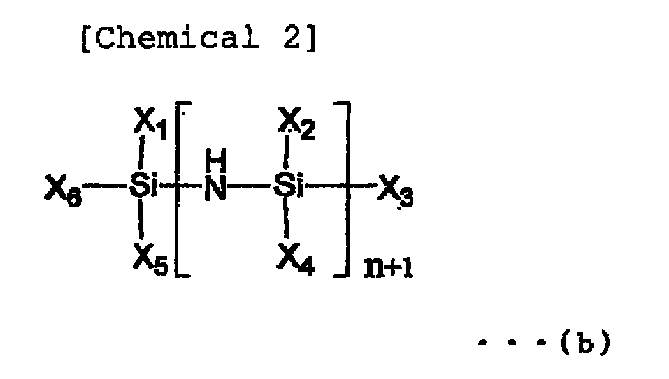
-

-

- In general formulas (a) to (d), m and n each independently represent an integer of 0 or more. X1 to X8 each independently represent hydrogen, a hydrocarbon group (including both saturated and unsaturated hydrocarbon groups) having 1 to 6 carbon atoms, an -OR1 group, a -CH2OR2 group, a -COOR3 group, an -OCOR4 group, an -SR5 group, a -CH2SR6 group, an -NR7 2 group, or a -CH2NR8 2 group [R1 to R8 each independently represent hydrogen or a hydrocarbon group (including both saturated and unsaturated hydrocarbon groups) having 1 to 6 carbon atoms. X1 to X8 may be arbitrary ones of the above functional groups and may all be the same or different.
- Specific examples of the hydrocarbon group having 1 to 6 carbon atoms represented by R1 to R8 include a methyl group, ethyl group, n-propyl group, isopropyl group, n-butyl group, isobutyl group, pentyl group, hexyl group, vinyl group, allyl group, ethynyl group, phenyl group, cyclohexyl group, propenyl group, and isopropenyl group.
- Specific examples of the compound represented by general formula (a) include trimethylsilanol, tetramethylsilane, diethylsilane, dimethylethoxysilane, hydroxymethyltrimethylsilane, methoxytrimethylsilane, dimethoxydimethylsilane, methyltrimethoxysilane, mercaptomethyltrimethoxysilane, tetramethoxysilane, mercaptomethyltrimethylsilane, aminomethyltrimethylsilane, dimethyl(dimethylamino)silane, ethynyltrimethylsilane, diacetoxymethylsilane, allyldimethylsilane, trimethylvinylsilane, methoxydimethylvinylsilane, acetoxytrimethylsilane, trimethoxyvinylsilane, diethylmethylsilane, ethyltrimethylsilane, ethoxytrimethylsilane, diethoxymethylsilane, ethyltrimethoxysilane, dimethylaminotrimethylsilane, bis(dimethylamino)methylsilane, phenylsilane, dimethyldivinylsilane, 2-propynyloxytrimethylsilane, dimethylethoxyethynylsilane, diacetoxydimethylsilane, allyltrimethylsilane, allyloxytrimethylsilane, ethoxydimethylvinylsilane, isopropenoxytrimethylsilane, allylaminotrimethylsilane, trimethylpropylsilane, trimethylisopropylsilane, triethylsilane, diethyldimethylsilane, butyldimethylsilane, trimethylpropoxysilane, trimethylisopropoxysilane, triethylsilanol, diethoxydimethylsilane, propyltrimethoxysilane, diethylaminodimethylsilane, bis(ethylamino)dimethylsilane, bis(dimethylamino)dimethylsilane, tri(dimethylamino)silane, methylphenylsilane, methyltrivinylsilane, diacetoxymethylvinylsilane, methyltriacetoxysilane, allyloxydimethylvinylsilane, diethylmethylvinylsilane, diethoxymethylvinylsilane, bis(dimethylamino)methylvinylsilane, butyldimethylhydroxymethylsilane, 1-methylpropoxytrimethylsilane, isobutoxytrimethylsilane, butoxytrimethylsilane, butyltrimethoxysilane, methyltriethoxysilane, isopropylaminomethyltrimethylsilane, diethylaminotrimethylsilane, methyltri(dimethylamino)silane, dimethylphenylsilane, tetravinylsilane, triacetoxyvinylsilane, tetraacetoxysilane, ethyltriacetoxysilane, diallyldimethylsilane, 1,1-dimethylpropynyloxytrimethylsilane, diethoxydivinylsilane, butyldimethylvinylsilane, dimethylisobutoxyvinylsilane, acetoxytriethylsilane, triethoxyvinylsilane, tetraethylsilane, dimethyldipropylsilane, diethoxydiethylsilane, dimethyldipropoxysilane, ethyltriethoxysilane, tetraethoxysilane, methylphenylvinylsilane, phenyltrimethylsilane, dimethylhydroxymethylphenylsilane, phenoxytrimethylsilane, dimethoxymethylphenylsilane, phenyltrimethoxysilane, anilinotrimethylsilane, 1-cyclohexenyloxytrimethylsilane, cyclohexyloxytrimethylsilane, dimethylisopentyloxyvinylsilane, allyltriethoxysilane, tripropylsilane, butyldimethyl-3-hydroxypropylsilane, hexyloxytrimethylsilane, propyltriethoxysilane, hexyltrimethoxysilane, dimethylphenylvinylsilane, trimethylsilylbenzonate, dimethylethoxyphenylsilane, methyltriisopropenoxysilane, methoxytripropylsilane, dibutoxydimethylsilane, methyltripropoxysilane, bis(butylamino)dimethylsilane, divinylmethylphenylsilane, diacetoxymethylphenylsilane, diethylmethylphenylsilane, diethoxymethylphenylsilane, triisopropoxyvinylsilane, 2-ethylhexyloxytrimethylsilane, pentyltriethoxysilane, diphenylsilane, diphenylsilanediolphenyltrivinylsilane, triethylphenylsilane, phenyltriethoxysilane, tetraallyloxysilane, phenyltri(dimethylamino)silane, tetrapropoxysilane, tetraisopropoxysilane, diphenylmethylsilane, diallylmethylphenylsilane, dimethyldiphenylsilane, dimethoxydiphenylsilane, dianilinodimethylsilane, diphenylethoxymethylsilane, tripentyloxysilane, diphenyldivinylsilane, diacetoxydiphenylsilane, diethyldiphenylsilane, diethoxydiphenylsilane, bis(dimethylamino)diphenylsilane, tetrabutylsilane, tetrabutoxysilane, triphenylsilane, diallyldiphenylsilane, trihexylsilane, triphenoxyvinylsilane, 1,1,3,3-tetramethyldisiloxane, pentamethyldisiloxane, hexamethyldisiloxane, 1,3-dimethoxytetramethyldisiloxane, 1,3-diethinyl-1,1,3,3-tetramethyldisiloxane, 1,3-divinyl-1,1,3,3-tetramethyldisiloxane, 1,3-diethoxytetramethyldisiloxane, hexaethyldisiloxane, and 1,3-dibutyl-1,1,3,3-tetramethyldisiloxane.
- Specific examples of the compound represented by general formula (b) include 1,1,3,3-tetramethyldisilazane, hexamethyldisilazane, and 1,3-divinyl-1,1,3,3-tetramethyldisilazane.
- Specific examples of the compound represented by general formula (c) include hexamethylcyclotrisiloxane, hexaethylcyclotrisiloxane, 1,3,5,7-tetramethylcyclotetrasiloxane, and octamethylcyclotetrasiloxane.
- Specific examples of the compound represented by general formula (d) include 1,1,3,3,5,5-hexamethylcyclotrisilazane and 1,1,3,3,5,5,7,7-octamethylcyclotetrasilazane.
- The number average molecular weights of these organosilicon compounds fall within the range of preferably 48 to 600 and most preferably 140 to 500 from the viewpoint of control of organic components in hybrid films and the strengths of the films themselves.
- A non-silicon-containing organic compound of the hybrid layer includes preferably a compound containing hydrogen and carbon as indispensable components and having a reactive group at its side chain or terminal, and more specifically a compound represented by general formulas (e) to (g).
- General formula (e): non-silicon-containing organic compound containing carbon and hydrogen as indispensable components and having an epoxy group at one terminal

- General formula (f): non-silicon-containing organic compound containing carbon and hydrogen as indispensable components and having epoxy groups at two terminals

- General formula (g): non-silicon-containing organic compound containing carbon and hydrogen as indispensable components and having a double bond
CX9X10 = CX11X12 (g)
- In general formulas (e) and (f), R9 represents hydrogen or a hydrocarbon group which has 1 to 10 carbon atoms and may contain oxygen, and R10 represents a divalent hydrocarbon group which has 1 to 7 carbon atoms and may contain oxygen. In general formula (g), X9 to X12 each independently represent hydrogen, a hydrocarbon group having 1 to 10 carbon atoms, or an organic group containing hydrogen and carbon having 1 to 10 carbon atoms as indispensable components and at least one of oxygen and nitrogen as an indispensable component.
- Specific examples of the compound represented by general formula (e) include methyl glycidyl ether, butyl glycidyl ether, 2-ethylhexydyl glycidyl ether, decyl glycidyl ether, stearyl glycidyl ether, allyl glycidyl ether, phenyl glycidyl ether, p-sec-butylphenyl glycidyl ether, p-tert-butylphenyl glycidyl ether, 2-methyloctyl glycidyl ether, glycidol, trimethylol, and propane polyglycidyl ether.
- Specific examples of the compound represented by general formula (f) include neopentyl glycol diglycidyl ether, glycerol diglycidyl ether, glycerol triglycidyl ether, propylene glycol diglycidyl ether, tripropylene glycol diglycidyl ether, polypropylene glycol diglycidyl ether, 1,6-hexanediol diglycidyl ether, ethylene glycol diglycidyl ether, diethylene glycol diglycidyl ether, and polyethylene glycol diglycidyl ether.
- Specific examples of general formula (g) include ethylene, propylene, vinyl chloride, vinyl fluoride, acrylamide, vinylpyrrolidone, vinylcarbazole, methyl methacrylate, ethyl methacrylate, benzyl methacrylate, n-butyl methacrylate, isobutyl methacrylate, dimethyl amino ethyl methacrylate, mathacrylic acid, glycidyl methacrylate, vinyl acetate, and styrene.
- The number average molecular weights of these compounds represented by general formulas (e) to (g) fall within the range of preferably 28 to 4,000 and most preferably 140 to 360 in consideration of control of organic components in hybrid films and the strengths of the films themselves.
- As a method of forming an organosilicon compound which is liquid at normal temperature and normal pressure and/or a non-silicon-containing organic compound (to be also referred to as an organic material hereinafter) which is liquid at normal temperature and normal pressure, it is preferable to simultaneously deposit hybrid films using different vapor sources of inorganic and organic materials. More specifically, an inorganic material is heated to evaporate using an electron gun or the like. An organic material is stored in an external tank and evaporated in this tank. The inorganic and organic materials are then simultaneously deposited.
- Preferably, the external tank which stores an organic material is heated and evacuated, the organic material is supplied to the chamber, and oxygen gas and/or argon gas is used to perform ion-assisted deposition in view of deposition rate control. In the present invention, the organic material is liquid at normal temperature and normal pressure. The present invention does not need a solvent, and allows direct heating and evaporation of the organic material. It is effective to arrange the supply port of the organic material right above the inorganic material vapor source to improve impact resistance and wear resistance. It is preferable to supply the organosilicon compound upward and supply downward the non-silicon-containing organic compound having a reactive group at its side chain or terminal and containing carbon and hydrogen as indispensable components.
- The heating temperature of the external tank falls within the range of 30 to 200°C and preferably 50 to 150°C to obtain an appropriate deposition rate, depending on the vaporization temperatures of organic materials.
- The content of the organic material in the hybrid layer according to the present invention falls within the range of 0.020 to 25 wt% particularly in consideration of a better physical property improvement effect.
- The preferable film thickness and refractive index ranges of the present invention are as follow. In this case, λ represents the wavelength of light.
First layer 0.005λ to 1.25λ 1.41 to 1.50 Second layer 0.005λ to 0.10λ 2.00 to 2.35 Third layer 0.005λ to 1.25λ 1.41 to 1.50 Fourth layer 0.05λ to 0.45λ 2.00 to 2.35 Fifth layer 0.005λ to 0.15λ 1.41 to 1.50 Sixth layer 0.05λ to 0.45λ 2.00 to 2.35 Seventh layer 0.2λ to 0.29λ 1.41 to 1.50 - The uppermost water-
repellent film layer 67 improves the smoothness of the convexoptical surface 2a and the concaveoptical surface 2b to improve the antifouling property and prevent water stain. A super water-repellent lens excellent in slide property is recently popular. A water-repellent agent made from an organosilicon compound containing a fluorine-substituted alkyl group is used as the water-repellent agent. - The material and formation method of the water-
repellent film layer 67 preferably employ a method described in Japanese Patent Laid-Open No.2004-122238 - A compound represented by general formula (h) or unit formula (i) is preferably used as the organosilicon compound containing the fluorine-substituted alkyl group.
-

- In general formula (h), RF represents a straight chain perfluoroalkyl group having 1 to 16 carbon atoms, X represents hydrogen or a lower alkyl group having 1 to 5 carbon atoms, R11 represents a hydrolyzable group, k is an integer of 1 to 50, r is an integer of 0 to 2, and p is an integer of 1 to 10.
CqF2q+1CH2CH2Si (NH2)3 (i)
wherein q is an integer of 1 or more. - Examples of the hydrolyzable group represented by R11 include an amino group, an alkoxy group particularly an alkoxy group including an alkyl part having 1 to 2 carbon atoms, and a chlorine atom.
- Specific examples of the compound represented by unit formula (i) include n-CF3CH2CH2Si(NH2)3; n-trifluoro(1,1,2,2-tetrahydro)propylsilazane, n-C3F7CH2CH2Si(NH2)3; n-heptafluoro(1,1,2,2-tetra-hydro)pentylsilazane, n-C4F9CH2CH2Si(NH2)3; n-nonafluoro(1,1,2,2-tetrahydro)hexylsilazane, n-C6F13CH2CH2Si2(NH2)3; n-trideofluoro (1,1,2,2-tetra-hydro) octylsilazane, and n-C8F17CH2CH2Si(NH2)3; n-heptadecafluoro(1,1,2,2-tetrahydro)decylsilazane.
- The material of the water-
repellent film layer 67 may contain as two major components the organosilicon compound containing the fluorine-substituted alkyl group and perfluoropolyeter not containing silicon. In addition, a first layer may be formed from these major components, and a second layer may be formed on the first layer using a material containing as a major component perfluoropolyether not containing silicon, thereby forming the water-repellent film layer. - The perfluoropolyether not containing silicon preferably employs a compound consisting of a unit having the following structural formula:
-(R12O)- (j)
In formula (j), R12 represents a perfluoroalkylene group having 1 to 3 carbon atoms. The average molecular weight falls within the range of 1,000 to 10,000 and more preferably 2,000 to 10,000. R represents a perfluoroalkylene group having 1 to 3 carbon atoms, and its specific examples include groups such as CF2, CF2-CF2, CF2CF2CF2, and CF(CF2)CF2. These perfluoropolyethers are liquid at normal temperature and called fluorine oils. - In the spectacle lens of the present invention, a layer made from at least one metal selected from metals having a catalyst function in forming a hybrid layer (to be described later), such as nickel (Ni), silver (Ag), platinum (Pt), niobium (Nb), and titanium (Ti) can be formed as an underlayer below an antireflection film layer in order to improve the bonding property. The most preferable underlayer is a metal layer made from niobium to impart better impact resistance. Use of the metal layer as the underlayer enhances the reaction with the hybrid layer formed on the underlayer, thereby obtaining a material having an intra-molecular network structure and improving the impact resistance.
- According to the present invention, it is also preferable to form a double layer structure inside the uppermost water-
repellent film layer 67, i.e., the first and second water-repellent layers. For example, a vapor material containing a mixture of the organosilicon compound containing the fluorine-substituted alkyl group represented by general formula (I) and at least one silane compound selected from the following general formulas (II-1), (II-2), and (II-3) is deposited on the optical member to form the first water-repellent layer. The resultant structure is dipped in a dipping material containing a solvent and perfluoropolyether-polysiloxane copolymer modified silane represented by general formula (III) to form the second water-repellent layer, thereby forming a water-repellent film layer 67 made from the two layers. -

- In general formula (I), Rf represents a divalent group which includes a unit represented by formula -(CkF2kO)- (wherein k is an integer of 1 to 6) and has an unbranched straight chain perfluoropolyalkylene ether structure. R independently represents a monovalent hydrocarbon group having 1 to 8 carbon atoms. X independently represents a hydrolyzable group or halogen atom, n and n' each represent an integer of 0 to 2, m and m' each represent an integer of 1 to 5, and a and b each represent 2 or 3.
-
[Chemical 9] General formula (II-1) R'-Si(OR")3
General formula (II-2) Si(OR")4
General formula (II-3) SiO(OR")3Si(OR")3
wherein R' represents an organic group and R" represents an alkyl group. -

- In general formula (III), Rg represents a divalent group which includes a repeating unit represented by formula -(CjF2jO)- (wherein j is an integer of 1 to 5) and has an unbranched straight chain perfluoropolyalkylene ether structure. The repeating unit count is 30 to 60. Different j repeating units may be simultaneously included. R1 represents the same or different alkyl groups or phenyl groups having 1 to 4 carbon atoms, w is 30 to 100, and a, b, and c each independently represent an integer of 1 to 5. R2 represents an alkyl group or phenyl group having 1 to 4 carbon atoms, X1 represents a hydrolyzable group, d is 2 or 3, and y is an integer of 1 to 5.
The compounds represented by general formulas (I) to (III) will be described below. - In general formula (I), the Rf group is a divalent group which includes a unit represented by formula -(CkF2kO)- (wherein k is an integer of 1 to 6 and preferably 1 to 4, and the sequence of CkF2kO in general formula (I) is random) and has an unbranched straight chain perfluoropolyalkylene ether structure. Note that when both n and n' in general formula (I) are zero, the terminal of the Rf group bonded to the oxygen atom (O) in general formula (I) is not an oxygen atom:
- wherein Rf represents a divalent straight chain perfluoropolyether group and include perfluoropolyether groups having a variety of chain lengths. Rf preferably represents a divalent straight chain perfluoropolyether having a perfluoropolyether having 1 to 6 carbon atoms as the repeating unit. Examples of this divalent straight chain perfluoropolyether are as follows:
-CF2CF2O(CF2CF2CF2O)rCF2CF2-
-CF2(OC2F4)5-(OCF2)t-
wherein r, s, and t each represent an integer of 1 or more. More specifically, r, s, and t each fall within the range of 1 to 50 and more preferably 10 to 40. Note the perfluoropolyether molecular structure is not limited to the exemplified structures. - In general formula (I), X represents a hydrolyzable group or halogen atom. Examples of X as the hydrolyzable group include an alkoxy group such as a methoxy group, ethoxy group, propoxy group, or butoxy group; an alkoxyalkoxy group such as a methoxymethoxy group, methoxyethoxy group, or ethoxyethoxy group; an alkenyloxy group such as an allyloxy group or isopropenoxy group; an asiloxy group such as an acetoxy group, propyonyloxy group, butylcarbonyloxy group, or benzoyloxy group; a ketoxime group such as a dimethylketoxime group, methylethylketoxime group, diethylketoxime group, cyclopentanoxime group, or cyclohexanoxime group; an amino group such as an N-methylamino group, N-ethylamino group, N-propylamino group, N-butylamino group, N,N-dimethylamino group, N,N-diethylamino group, or N-cyclohexylamino group; an amide group such as an N-methylacetoamide group, N-ethylacetoamide group, or N-methylbenzamide group; and an aminooxy group such as an N,N-dimethylaminooxy group or N,N-diethylaminooxy group.
Examples of X as the halogen atom include a chlorine atom, bromine atom, and iodine atom.
Among them all, the methoxy group, ethoxy group, isopropenoxy group, and chlorine atom are most preferable. - In general formula (I), R represents a monovalent hydrocarbon group having 1 to 8 carbon atoms. If R represents a plurality of monovalent hydrogen groups, they may be the same or different. Specific examples of R include an alkyl group such as a methyl group, ethyl group, propyl group, butyl group, pentyl group, hexyl group, heptyl group, or octyl group; a cycloalkyl group such as a cyclopentyl group or cyclohexyl group; an aryl group such as a phenyl group, tolyl group, or xylyl group; an aralkyl group such as a benzyl group or phenetyl group; and an alkenyl group such as a vinyl group, allyl group, butenyl group, pentenyl group, or hexenyl group. Among them all, a monovalent hydrocarbon group having 1 to 3 carbon atoms is preferable, and the methyl group is most preferable.
- In general formula (I), n and n' each represent an integer of 0 to 2 and preferably 1, and may be the same or different, m and m' each represent an integer of 1 to 5, preferably 3, and may be the same or different.
- Next, a and b each represent 2 or 3 and preferably 3 in view of hydrolysis, condensation reactivity, and bonding property.
- The molecular weight of the organosilicon compound containing the fluorine-substituted alkyl group represented by general formula (I) is not particularly limited, but its number average molecular weight appropriately falls within the range of 500 to 20,000 and preferably 1,000 to 10,000 in view of stability and handling.
- Specific examples of the organosilicon compound containing the fluorine-substituted alkyl group represented by structural formula (I) are as follows, but are not limited to the exemplified compounds.
(CH3O)3SiCH2CH2CH2OCH2CF2CF2O(CF2CF2CF2O)1CF2CF2CH2OCH2CH2- CHSi (OCH3)
(CH3O)2CH3SiCH2CH2CH2OCH2CF2CF2O(CF2CF2CF2O)1CF2CF2CH2OCH2CH2-CH2SiCH3(OCH3)2(CH3O)3SiCH2CH2CH2OCH2CF2(OC2F4)p(OCF2)qOCF2-CH2OCH2CH2CH2Si(OCH3)3
(CH3O)2CH3SiCH2CH2CH2OCH2CH2CF2(OC2F4)p(OCF2)qOCF2CH2OCH2CH2-CH2SiCH3(OCH3)2
(CH3O)3SiCH2CH2CH2OCH2CH2CF2(OC2F4)p(OCF2)qOCF2CH2CH2OCH2CH2-CH2Si(OCH3)3
(C2H5O)3SiCH2CH2CH2OCH2CH2CF2(OC2F4)p(OCF2)qOCF2CH2OCH2CH2CH2-Si(OC2H5)3
- The compound represented by general formula (I) can be used singly or in a combination of two or more compounds. In some case, the organosilicon compound containing the fluorine-substituted alkyl group and its partial hydrolyzed condensate can be combined and used. In addition, perfluoropolyether-polysiloxane copolymer modified silane represented by general formula (III) can be combined and used with the compound represented by general formula (I).
- The organosilicon compound containing the fluorine-substituted alkyl group represented by general formula (I) is preferably diluted with a solvent. Examples of a solvent to be used include a fluorine-modified aliphatic hydrocarbon solvent (e.g., perfluoroheptane or perfluorooctane), a fluorine-modified aromatic hydrocarbon solvent (e.g., 1,3-di(trifluoromethyl)benzene or trifluoromethylbenzene), a fluorine-modified ether solvent (e.g., methylperfluorobutyl ether or perfluoro(2-butyltetrahydrofurane), a fluorine-modified alkylamine solvent (e.g., perfluorotributylamine or perfluorotripentylamine), a hydrocarbon solvent (e.g., petroleum benzene, mineral spirits, toluene, or xylene), a ketone solvent (e.g., acetone, methyl ethyl ketone, or methyl isobutyl ketone), and an alcohol solvent (methanol, ethanol, isopropanol, or n-propanol). These solvents can be used singly or in a combination of two or more solvents. Among them all, a fluorine-modified solvent is preferable in view of the dissolvability and wettability of modified silane. Examples of the most preferable solvent include 1,3-di(trifluoromethyl)benzene, perfluoro(2-butyltetrahydrofurane), and perfluorotributylamine.
- One silane compound selected from the general formulas (II-1), (II-2), and (II-3) comprises the following:
General formula (II-1) R'-Si(OR")3
General formula (II-2) Si(OR")4
General formula (II-3) SiO(OR")33Si(OR")3
- wherein R' represents an organic group. Examples of R' include an alkyl group (e.g., a methyl group, ethyl group, or propyl group) having 1 to 50 carbon atoms (preferably 1 to 10 carbon atoms), an epoxyethyl group, a glycidyl group, and an amino group. These groups may be substituted. R" represents an alkyl group (e.g., a methyl group, ethyl group, or propyl group) having 1 to 48 carbon atoms and is preferably a methyl group or ethyl group.
- Specific examples of the silane compounds represented by general formulas (II-1) to (II-3) include structural formulas (C2H5O)3SiC3H6NH2, (CH3O)3SiC3H6NH2, (C2H5O)4Si, and (C2H5O)3Si-O-Si(OC2H5)3. However, the silane compound is not limited to the above examples.
- The silane compounds represented by general formulas (II-1) to (II-3) can be used singly or in a combination of two or more silane compounds.
The silane compound preferably contains the compound represented by general formula (II-1) singly or in an amount larger than those of other components. - Perfluoropolyether-polysiloxane copolymer modified silane represented by general formula (III)

- In general formula (III), the Rg group is a divalent group which includes repeating unit represented by formula -(CjF2jO)- (wherein j is an integer of 1 to 5 and preferably 1 to 3, and the sequence of CjF2jO in general formula (III) is random) and has an unbranched straight chain perfuluoropolyalkylene ether structure. The repeating unit count is 30 to 60 (preferably 30 to 50). Different j repetition counts may be simultaneously included:
- wherein Rg represents a divalent straight chain perfluoropolyether group and include perfluoropolyether groups having a variety of chain lengths. Rg preferably represents a divalent straight chain perfluoropolyether having a perfluoropolyether having about 1 to 5 carbon atoms as the repeating unit. Examples of this divalent straight chain perfluoropolyether are as follows:
-CF2CF2O(CF2CFCF2O)kCF2CF2-
-CF2(OC2F4)p-(OCF2)q-
wherein k, p, and q each represent an integer of 1 or more, and k and p+q preferably fall within the range of 30 to 60. Note the perfluoropolyether molecular structure is not limited to the exemplified structures. - In general formula (III), R1 represents an alkyl group (e.g., a methyl group, ethyl group, propyl group, or butyl group) or phenyl group having 1 to 4 carbon atoms. The alkyl groups or phenyl groups may be the same or different.
In general formula (III), w is 30 to 100 and preferably 30 to 60, and a, b, and c each independently represent an integer of 1 to 5 and preferably 1 to 3.
In general formula (III), R2 represents an alkyl group (e.g., a methyl group, ethyl group, propyl group, or butyl group) or phenyl group having 1 to 4 carbon atoms. - In general formula (III), X1 represents a hydrolyzable group. Examples of X1 include an alkoxy group such as a methoxy group, ethoxy group, propoxy group, or butoxy group; an alkoxyalkoxy group such as a methoxymethoxy group, methoxyethoxy group, or ethoxyethoxy group; alkenyloxy group such as an allyloxy group or isopropenoxy group; an acyloxy group such as an acetoxy group, propionyloxy group, butylcarbonyloxy group, or benzoyloxy group; a ketoxime group such as a dimethylketoxime group, methylethylketoxime group, diethylketoxime group, cyclopentanoxime group, or cyclohexanoxime group; an amino group such as an N-methylamino group, N-ethylamino group, N-propylamino group, N-butylamino group, N,N-dimethylamino group, N,N-diethylamino group, or N-cyclohexylamino group; an amide group such as an N-methylacetoamide group, N-ethylacetoamide group, or N-methylbenzamide group; and an aminooxy group such as an N,N-dimethylaminooxy group or N,N-diethylaminooxy group. Among them all, the methoxy group, ethoxy group, and isopropynoxy group are preferable.
- In general formula (III), d is 2 or 3 and preferably 3 in consideration of hydrolysis, condensation reactivity, and film bonding property, and y is an integer of 1 to 5 and preferably 1 to 3.
The compounds represented by general formula (III) can be used singly or in a combination of two or more compounds. - The material of the plastic base member used in the present invention is not limited to a specific material. Examples of the plastic base member include a methyl methacrylate homopolymer, a copolymer formed from methyl methacrylate and at least another monomer, a homopolymer made from diethylene glycol bisallylcarbonate, a copolymer formed from diethylene glycol bis(allyl carbonate) and at least another monomer, a sulfur-containing copolymer, a halogen copolymer, and a polymer using as a material a compound including polycarbonate, polystyrene, polyvinyl chloride, unsaturated polyester, polyethylene terephtalate, polyurethane, polythiourethane, or epithio group.
- Examples of the compound having the epithio group include chain organic compounds such as bis(β-epithiopropylthio)metane, 1,2-bis(β-epithiopropylthio)ethane, 1,3-bis(β-epithiopropylthio)propane, 1-2-(β-epithiopropylthio)propane, 1-(β-epithiopropylthio)-2-(β-epithiopropylthio)propane, 1,4-bis(β-epithiopropylthio)butane, 1,3-bis(β-epithiopropylthio)butane, 1-(β-epithiopropylthio)-3-(β-epithiopropylthiomethyl)butane, 1,5-bis(β-epithiopropylthio)pentane, 1-(β-epithiopropylthio)-4-(β-epithiopropylthiomethyl)pentane, 1,6-bis(β-epithiopropylthio)hexane, 1-(β-epithiopropylthio)-5-(β-epithiopropylthiomethyl)hexane, 1-(β-epithiopropylthio)-2-[(2-β-epithiopropylthioethyl)thio]ethane, and 1-(β-epithiopropylthio)-2-[[2-(2-β-epithiopropylthioethyl)thioethyl]thio]ethane. Examples of the compound having the epithio group also include branched organic compounds and compounds obtained by substituting at least one hydrogen of the episulfide group of each of these compounds with a methyl group. Specific examples of the branched organic compounds include tetrakis(β-epithiopropylthiomethyl)methane, 1,1,1-tris(β-epithiopropylthiomethyl)propane, 1,5-bis(β-epithiopropylthio)-2-(β-epithiopropylthiomethyl)-3-thiapentane, 1,5-bis(β-epithiopropylthio)-2,4-bis(β-epithiopropylthiomethyl)-3-thiopentane, 1-(β-epithiopropylthio)-2,2-bis(β-epithiopropylthiomethyl)-4-thiahexane, 1,5,6-tris(β-epithiopropylthio)-4-(β-epithiopropylthiomethyl)-3-thiahexane, 1,8-bis(β-epithiopropylthio)-4-(β-epithiopropylthiomethyl)-3,6-dithiaoctane, 1,8-bis(β-epithiopropylthio)-4,5-bis(β-epithiopropylthiomethyl)-3,6-dithiaoctane, 1,8-bis(β-epithiopropylthio)-4,4-bis(β-epithiopropylthiomethyl)-3,6-dithiaoctane, 1,8-bis(β-epithiopropylthio)-2,4,5-tris(β-epithiopropylthiomethyl)-3,6-dithiaoctane, 1,8-bis(β-epithiopropylthio)-2,5-bis(β-epithiopropylthiomethyl)-3,6-dithiaoctane, 1,9-bis(β-epithiopropylthio)-5-(β-epithiopropylthiomethyl)-5-[(2-β-epithiopropylthioethyl)thiomethyl]-3,7-dithianonane, 1,10-bis(β-epithiopropylthio)-5,6-bis[(2-β-epithiopropylthioethyl)thio]-3,6,9-trithiadecane, 1,11-bis(β-epithiopropylthio)-4,8-bis(β-epithiopropylthiomethyl)-3,6,9-trithiaundecane, 1,11-bis(β-epithiopropylthio)-5,7-bis(β-epithiopropylthiomethyl)-3,6,9-trithiaundecane, 1,11-bis(β-epithiopropylthio)-5,7-[(2-β-epithiopropylthioethyl)thiomethyl]-3,6,9-trithiaundecane, and 1,11-bis(β-epithiopropylthio)-4,7-bis(β-epithiopropylthiomethyl)-3,6,9-trithiaundecane. Examples of the compound having the epithio group further include alicyclic organic compounds and compounds obtained by substituting at least one hydrogen of the episulfide group of each of these compounds with a methyl group, and aromatic organic compounds and compounds obtained by substituting at least one hydrogen of the episulfide group of each of these compounds with a methyl group. Specific examples of the alicyclic organic compound include 1,3- and 1,4-bis(β-epithiopropylthio)cyclohexane, 1,3- and 1,4-bis(β-epithiopropylthiomethyl)cyclohexane, bis[4-(β-epithiopropylthio)cyclohexyl]methane, 2,2-bis[4-(β-epithiopropylthio)cyclohexyl]propane, bis[4-(β-epithiopropylthio)cyclohexyl]sulfide, 2,5-bis(β-epithiopropylthiomethyl)-1,4-dithiane, and 2,5-bis(β-epithiopropylthioethylthiomethyl)-1,4-dithiane. Specific examples of the aromatic organic compound include 1,3- and 1,4-bis(β-epithiopropylthio)benzene, 1,3- and 1,4-bis(β-epithiopropylthiomethyl)benzene, bis[4-(β-epithiopropylthio)phenyl]methane, 2,2-bis[4-(β-epithiopropylthio)phenyl]propane, bis[4-(β-epithiopropylthio)phenyl]sulfide, bis[4-(β-epithiopropylthio)phenyl)sulfone, and 4,4'-bis(β-epithiopropylthio)biphenyl.
- Referring to
Figs. 1 and4 , thelens rotating shaft 4 includes first and secondlens rotating shafts lens holding unit 15. Thelens holding unit 15 has a pair ofsupports support 15a axially, rotatably supports the firstlens rotating shaft 4A, and theother support 15b axially supports the secondlens rotating shaft 4B to be rotatable and movable in the axial direction. As shown inFig. 2 , alens holder 16 andlens retainer 17 constituting the lens holding means for theprocessing target lens 2 are detachably attached to the opposing distal ends of the first and secondlens rotating shafts - A lens rotating
shaft driving motor 18 is fixed to theother support 15b of thelens holding unit 15. The rotation of the drivingmotor 18 is transmitted to the first and secondlens rotating shafts lens rotating shafts shaft driving motor 18, a reversible pulse motor with a variable rotation speed is used. A driving motor (not shown) which moves the secondlens rotating shaft 4B forward/backward with respect to the firstlens rotating shaft 4A is built in theother support 15b of thelens holding unit 15. - The first lens rotating
shaft moving mechanism 5 includes a pair of front and rear X-axislinear guides 31, an X-direction table 32, and an X-directiontable driving motor 33. The X-axis linear guides 31 are set on abottom plate 30 of thehousing 3 to be parallel to each other and are long in the X direction. The X-direction table 32 is movable in the X direction along the X-axis linear guides 31. The X-directiontable driving motor 33 moves the X-direction table 32 along the X-axis linear guides 31. - The second lens rotating
shaft moving mechanism 6 includes a pair of left and right Y-axislinear guides 35, a Y-direction table 36, a Y-directiontable driving motor 37, and thelens holding unit 15. The Y-axislinear guides 35 are set on the upper surface of the X-direction table 32 to be parallel to each other and extend in the Y direction. The Y-direction table 36 is movable in the Y direction along the Y-axis linear guides 35. The Y-directiontable driving motor 37 moves the Y-direction table 36 along the Y-axis linear guides 35. Thelens holding unit 15 is set on the Y-direction table 36. Thus, the operation of thelens rotating shaft 4 includes movements in three directions, i.e., rotation about the axis, movement in the horizontal direction (X direction) perpendicular to the axis, and movement in the back-and-forth direction (Y direction). The controller numerically controls the movements in the three directions based on the shape processing data on theprocessing target lens 2. - As the
processing tool 7 which grinds acircumferential surface 2c of theprocessing target lens 2, a grinding stone such as a cylindrical diamond wheel as shown inFig. 2 is employed and attached to a processingtool rotating shaft 40 of therotational drive mechanism 8. Theprocessing tool 7 includes a primary processing (rough processing) grinding wheel 7A and secondary processing (finishing) grindingwheel 7B. Abeveling groove 41 formed of an axi-symmetric V-shaped annular groove is formed in the outer circumferential surface of the secondaryprocessing grinding wheel 7B. - The
rotational drive mechanism 8 of theprocessing tool 7 includes aframe 44, the processingtool rotating shaft 40, an inverter type processingtool driving motor 45, and arotation transmitting mechanism 46 such as a pulley or toothed belt. Theframe 44 is set on thebottom plate 30 of thehousing 3. The processingtool rotating shaft 40 is cantilevered at the upper end of theframe 44. The processingtool driving motor 45 rotates the processingtool rotating shaft 40. Therotation transmitting mechanism 46 transmits the rotation of the processingtool driving motor 45 to the processingtool rotating shaft 40. The processingtool rotating shaft 40 is parallel to thelens rotating shaft 4 and located in front of it. - As shown in
Fig. 4 , the lensshape measurement unit 9 includes a pair of left andright measurement elements measurement elements optical surfaces processing target lens 2. The driving motor moves themeasurement elements optical surfaces circumferential surface 2c andcircumferential surfaces peripheral edges peripheral edges processing target lens 2 from the traces of themeasurement elements processing target lens 2. InFig. 4 ,reference numeral 2c denotes the circumferential surface of theprocessing target lens 2 before edging; 2d, the circumferential surface after primary processing; and 2d, the circumferential surface after secondary processing. - When measuring the shape of the
processing target lens 2 by the lensshape measurement unit 9, theprocessing target lens 2 is rotated. The left andright measurement elements optical surfaces processing target lens 2. In this state, thelens holding unit 15 is moved back and forth. Then, the shape of theprocessing target lens 2 can be measured. - The
chamfering mechanism 10 chamfers theedge portions 53A and 53B of theprocessing target lens 2 after secondary processing, and includes a pair of left andright chamfering tools 60, a chamfering driving motor 61, and arotation transmitting mechanism 62 such as a pulley or belt. The chamfering driving motor 61 drives thechamfering tools 60. Therotation transmitting mechanism 62 transmits the rotation of the chamfering driving motor 61 to thechamfering tools 60. As thechamfering tools 60, grinding tools such as diamond wheels are employed. - The procedure of edging the
processing target lens 2 by the spectaclelens edging apparatus 1 having the above structure will be described based on the flowchart shown inFig. 7 .
First, the optician as the order placing side transmits information on a spectacle lens needed by the manufacturer to the lens manufacturer's factory as the manufacturing side in an online manner (step S1). When requesting manufacture and delivery of the lens to the factory, the optician sends to the factory various types of information such as the material and prescription values of the lens, the specified processing values of the lens, spectacle frame information, layout information which specifies the eye point position, the bevel mode, the bevel position, and the bevel shape that are necessary for the lens manufacture. The spectacle frame information includes 3-dimensional lens frame shape data, approximate curved surface definition data, a frame PD (or DBL), an optical axis angle, and the circumferential length. - This request for manufacturing the spectacle lens from the optician to the factory is effective particularly when, e.g., requesting the manufacture of a lens having a water-repellent film layer (because primary processing by the optician is difficult if a water-repellent film layer is formed on the lens).
- At the factory, upon acquiring various types of information necessary for the manufacture of the spectacle lens from the optician, processing shape data, edged lens shape information, layout information, processing designation information and the like are created based on the acquired information, and input to the edging apparatus 1 (step S2).
- Subsequently, the operator selects among uncut lenses stored as the stock a lens complying with the ordered lens as the
processing target lens 2 and holds theoptical surface 2a of the selectedlens 2 using the lens holder 16 (step S3). - As shown in
Fig. 3 , thelens holder 16 includes ametal shaft portion 70 and a holdingcup 71 which is integrally molded with theshaft portion 70 and made of an elastic material. The holdingcup 71 includes ashaft portion 71A fixed to theshaft portion 70 and alens holding portion 71B integrally provided to the distal end face of theshaft portion 71A. Thelens holding portion 71B forms a rectangular plate. The front surface of thelens holding portion 71B forms alens holding surface 72. Thelens holding surface 72 forms a concave surface with a radius of curvature almost equal to that of the convexoptical surface 2a of thelens 2. Aleap tape 73 is adhered to thelens holding surface 72. When holding theprocessing target lens 2 using thelens holder 16, theleap tape 73 may be adhered to the convexoptical surface 2a by urging. At this time, thelens holder 16 is attached to theprocessing target lens 2 such that its center O coincides with aprocessing center position 21 serving as the rotation center of theprocessing target lens 2 when processing theprocessing target lens 2, as shown inFig. 5A . If the lens includes a cylinder axis, thelens holder 16 is attached to the lens by setting the cylinder axis at a predetermined angle. Theprocessing center position 21 of theprocessing target lens 2 coincides with a frame center B of the spectacle frame, or an optical center C of theprocessing target lens 2. - The operator displays two axial
deviation measuring marks Figs. 5A to 5C ) on the convexoptical surface 2a of the processing target lens 2 (step S4). Two reference position marks 80a and 80b are displayed on thelens holder 16 in advance, and the axialdeviation measuring marks marks lens holder 16 include two perpendicular straight lines extending through the center O and are displayed on the rear surface of thelens holding portion 71B. The reference position marks 80a and 80b are displayed on thelens holder 16 in advance before theprocessing target lens 2 is held. However, the present invention is not limited to this. The reference position marks 80a and 80b and axialdeviation measuring marks lens holder 16 andprocessing target lens 2 after theprocessing target lens 2 is held. - The axial
deviation measuring marks processing target lens 2 include two perpendicular straight lines extending through theprocessing center position 21. After thelens holder 16 holds thelens 2, the axialdeviation measuring marks marks mark 81a has a larger line width than that of theother mark 81b. - The
processing target lens 2 is mounted on the lens rotating shaft 4 (step S5). When mounting theprocessing target lens 2 on thelens rotating shaft 4, first, thelens holder 16 which holds theprocessing target lens 2 is mounted on the firstlens rotating shaft 4A. Thelens holder 16 can be mounted by fitting theshaft portion 70 in a recess formed in the distal end face of the firstlens rotating shaft 4A. - Subsequently, the second
lens rotating shaft 4B is moved forward to urge thelens retainer 17 attached to the distal end of the lens rotating shaft against the concaveoptical surface 2b of theprocessing target lens 2 through an elastic member 85 (Fig. 2 ). Thus, thelens holder 16 andlens retainer 17 sandwich and hold the processing center positions 21 of the convex and concaveoptical surfaces processing target lens 2, thus completely mounting the lens on thelens rotating shaft 4. - Then, the
lens rotating shaft 4 is rotated at a low speed, and thecircumferential surface 2c of theprocessing target lens 2 undergoes primary processing by theprocessing tool 7 based on the processing shape data (step S6). In primary processing, the primary processing grinding wheel 7A grinds thecircumferential surface 2c to form theprocessing target lens 2 into a primary shape. The primary shape of theprocessing target lens 2 obtained by primary processing is either a circle larger than a circle inscribed by the edgedlens shape 2A (Figs. 5A to 5C ) that complies with the frame shape of the spectacle frame, or an edged shape similar to the edgedlens shape 2A and larger than it by the processing margin of secondary processing. Acircle 88 larger than the circle inscribed by the edgedlens shape 2A is a circle having a radius (e.g., 50 mm) equal to or slightly larger than a value obtained by adding the processing margin of secondary processing to a maximum radius R (Fig. 5B ) of the edgedlens shape 2A. - When primary processing of the
processing target lens 2 is ended, the operator removes it from thelens rotating shaft 4 and measures its axial deviation (step S7). Assume that theprocessing target lens 2 has a water-repellent film layer. If theprocessing target lens 2 undergoes primary processing while it is held by a lens holding force almost equal to that for a general lens, as the processing resistance is large, axial deviation occurs easily. If secondary processing is performed with the axial deviation uncorrected, the lens becomes defective. - In view of this, after primary processing is ended, the
lens holder 16 is removed from the firstlens rotating shaft 4A, and whether axial deviation exists or not is checked from the reference position marks 80a and 80b and axialdeviation measuring marks -
Fig. 5B shows a case in which, as the result of primary processing, theprocessing center position 21 axially deviates from the center O of thelens holder 16 by -X1 in the X direction and by -Y1 in the Y direction and the rotation angle axially deviates counterclockwise by -θ1 with respect to thereference position mark 80a.Fig. 5C shows a case in which theprocessing center position 21 does not axially deviate with respect to the center O of thelens holder 16 and only the rotation angle axially deviates counterclockwise by θ2 with respect to thereference position mark 80a. - When axial deviation exists, the deviation amounts X1 and Y1 in the X and Y directions of the
processing center position 21 with respect to the center O of thelens holder 16, and the rotation angle θ1 or θ2 are measured. As the result of axial deviation measurement, if the deviation amounts of theprocessing center position 21 in the X and Y directions are ±0.5 mm or more, or if the rotation angle is ±5° or more, it is determined that theprocessing center position 21 axially deviates. Otherwise, it is determined that axial deviation does not exist. The allowable values of the axial deviation amounts and rotation angle differ depending on the type and dioptric power of the lens. For example, when the target lens is a single-vision lens having a cylinder axis, if the deviation of the rotation angle described above is ±2° or less, the specifications of the spectacle lens may be satisfied. The tolerance is accordingly selected appropriately. - This axial deviation measurement is performed by the operator visually, or by known image processing. When image processing is employed, it is advantageous because the deviation amount can be measured more accurately than by visual measurement. Correction of processing shape data by means of image processing will further be described later.
- As the result of measurement, when it is determined that axial deviation exists, the
processing target lens 2 is held again by thelens holder 16, and the axial deviation is corrected (in step S8). More specifically, thelens holder 16 is removed from theprocessing target lens 2. Thelens holder 16 is then mounted again on theprocessing target lens 2 such that the center O of thelens holder 16 coincides with theprocessing center position 21 of theprocessing target lens 2 and that the reference position marks 80a and 80b coincide with the axialdeviation measuring marks lens holder 16 need not be removed from theprocessing target lens 2. - Subsequently, the
processing target lens 2 is mounted on thelens rotating shaft 4 again in accordance with the same procedure as in step S5 described above (step S9). - After the
processing target lens 2 is mounted on thelens rotating shaft 4, thelens rotating shaft 4 is rotated, and thecircumferential surface 2d of theprocessing target lens 2 that has been primarily processed undergoes secondary processing by the secondaryprocessing grinding wheel 7B into a secondary shape based on the processing shape data (step S10). The secondary shape of theprocessing target lens 2 by secondary processing is an edged lens shape that complies with the edgedlens shape 2A of the spectacle frame, or an edged lens shape slightly larger than this. The edged lens shape slightly larger than that of the spectacle frame is aimed at reserving, based on the order from the optician, a processing margin necessary when the optician performs finishing. The secondary shape of the processing target lens by secondary processing is calculated in advance in the same manner as the primary shape and input to the controller as processing shape data. - This embodiment employs the
grinding wheel 7B having the bevelinggroove 41, because it is aimed at the manufacture of a spectacle lens to be mounted on a general rimmed spectacle frame. When manufacturing a spectacle lens to be mounted on a spectacle frame not having a rim (rimless spectacle) or a spectacle lens to be mounted on a nylol frame, the circumferential surface of theprocessing target lens 2 may be edged by exchanging thegrinding wheel 7B for a grinding wheel for a rimless spectacle frame or nylol frame. - When secondary processing is ended, the
processing target lens 2 is removed from thelens rotating shaft 4, and its axial deviation is measured (step S11). The axial deviation is determined in accordance with whether or not the reference position marks 80a and 80b deviate from the axialdeviation measuring marks processing target lens 2 which has undergone primary processing and thus has a small diameter is to be processed. Therefore, even if the lens has a low processing resistance and is formed with a water-repellent film layer, axial deviation rarely occurs, or can be suppressed within the predetermined allowable value range. Thus, highly accurate processing can be performed. When the operator visually confirms that the axialdeviation measuring marks processing target lens 2 is free from axial deviation. - When secondary processing is ended, chamfering is performed (step S12). Chamfering is performed by rotating the
processing target lens 2 together with thelens rotating shaft 4 and urging thechamfering tools 60 against theedge portions 53A and 53B of thecircumferential surface 2e. The chamfering trace data of thechamfering tools 60 which are used as the control data of thechamfering tools 60 during chamfering are calculated based on position data of theedge portions 53A and 53B of thecircumferential surface 2e of theprocessing target lens 2 which are calculated after secondary processing. - When chamfering is ended, the
processing target lens 2 is removed from thelens rotating shaft 4, and optical performance and appearance test is performed (step S13). - A
processing target lens 2 determined as an acceptable product is packaged as a spectacle lens and delivered to the optician who placed the order (step S14). - Upon reception of the spectacle lens from the factory, the optician tests its optical performance and appearance. When the optician determines that the spectacle lens is appropriate, if the spectacle lens has an edged lens shape complying with the frame shape of the spectacle frame selected by the user, the optician fits the lens in the spectacle frame and delivers the spectacle frame to the user. If the spectacle lens has an edged lens shape slightly larger than the frame shape of the spectacle frame, the optician finishes the lens so as to comply with the frame shape of the spectacle lens and fits it in the spectacle frame, and delivers the spectacle frame to the user. In finishing by the optician, since the shape of the lens itself is small and accordingly the processing resistance is low, even if the lens is formed with a water-repellent film layer, the lens rarely deviates axially.
- In this manner, in this embodiment, the step of correcting the axial deviation of the processing target lens includes the axial deviation measuring step of removing the processing target lens from the lens rotating shaft together with the lens holding means after primary processing and measuring the axial deviation of the processing target lens from the reference position mark and the axial deviation measuring mark, the axial deviation correcting step of correcting the axial deviation of the processing target lens which is measured by the axial deviation measuring step by holding one optical surface of the processing target lens with the lens holding means again such that the axial deviation measuring mark coincides with the reference position mark, and the step of mounting the lens holding means on the lens rotating shaft again together with the processing target lens. Thus, in secondary processing, the lens can be processed without causing axial deviation, in the same manner as a general lens. More specifically, this embodiment allows axial deviation of the
processing target lens 2 in primary processing. If theprocessing target lens 2 axially deviates due to primary processing, the amount and direction of the axial deviation are measured, and the axial deviation is corrected by holding theprocessing target lens 2 again by thelens holder 16. When the axial deviation of theprocessing target lens 2 is corrected in this manner in secondary processing, since the shape of the lens itself in secondary processing is small, even when the lens has a water-repellent film layer, the axial deviation amount can be suppressed within the allowable value range without holding the lens with a particularly large lens holding force. Hence, even when theprocessing target lens 2 is a highly lubricant lens or an uncut lens having a large diameter in primary processing, no particular axial deviation preventive countermeasure is needed in the primary processing step. Such a lens can be processed highly accurately without causing axial deviation in the same manner as a general lens, even if the lens is not held with a particularly large lens holding force. -
Fig. 8 is a flowchart showing another embodiment of the present invention.
This embodiment is different from the embodiment described above in terms of how axial deviation is corrected. More specifically, according to the measurement and correction of axial deviation in this embodiment (step S27), axial deviation is measured by image processing, and the processing shape data itself of anedging apparatus 1 is corrected. - The procedure for this will be described hereinafter.
When measuring axial deviation by image processing, aline sensor 90 is arranged on a straight line extending through a center O of alens holder 16, as shown inFig. 9 . At least two reference position marks 80a and 80b and axialdeviation measuring marks lens holder 16 and aprocessing target lens 2 in advance to coincide with each other. When themarks processing target lens 2 in the mounted state can be discriminated in the vertical and horizontal directions and the like. - When primary processing is ended, the
processing target lens 2 is removed from alens rotating shaft 4 together with thelens holder 16, and theline sensor 90 obtains the images of the reference position marks 80a and 80b and axialdeviation measuring marks deviation measuring marks processing target lens 2 in the direction of the arrow. If the marks deviate, the deviation amounts are calculated; if do not, theprocessing target lens 2 is mounted on thelens rotating shaft 4 again and undergoes secondary processing. - When calculating the axial deviation amounts, the reference position is determined on the center O of the
lens holder 16 of a case in which the marks do not deviate. In other words, the reference position is determined on a position where straight lines extending from the two reference position marks 80a and 80b of thelens holder 16 intersect. The coordinate values of a point 21' where the straight lines extending from the axialdeviation measuring marks processing target lens 2 intersect are calculated, and the processing center position on theprocessing target lens 2 resulted from the axial deviation is specified (to be referred to as the processing center position 21' hereinafter). - Subsequently, as the deviation amount in a direction perpendicular to the
lens rotating shaft 4, the distance and direction to the processing center position 21' with reference to the center O of thelens holder 16 are calculated and determined as a correction value A (X, Y). The processing center position of theedging apparatus 1 expressed by the correction value A is determined as the processing center 21' on theprocessing target lens 2 deviating from the center O of thelens holder 16. As the deviation amount in the rotational direction, angles formed by the respective axialdeviation measuring marks - In this manner, after the axial deviation of the
processing target lens 2 is measured by image processing, the processing shaft center of the processing shape data itself of theprocessing target lens 2 is corrected, and secondary processing is performed based on the corrected processing shape data. Then, even if theprocessing target lens 2 actually, axially deviates, it need not be removed from thelens holder 16 and held again by it. Thus, a fewer number of operation steps are required than in the embodiment described above, and the time necessary for edging can be shortened greatly, which is advantageous. Steps S21 to S26 and steps S28 to S33 are completely the same as steps S1 to S6 and steps S9 to S14 shown inFig. 7 , and a repetitive description thereof will be omitted. - In this manner, according to this embodiment, the step of correcting the axial deviation of the processing target lens comprises the step of removing the processing target lens from the lens rotating shaft together with the lens holding means after primary processing, measuring the axial deviation of the processing target lens from the reference position mark and the axial deviation measuring mark, and correcting the processing shape data. In the secondary processing step, the processing target lens is processed based on the processing shape data corrected by the processing shape data correcting step. That is, the processing shape data itself is corrected in accordance with the measured axial deviation amount and its direction. Therefore, even when the processing target lens axially deviates from the lens holding means, the lens need not be removed from the lens holding means and held again by it, and can undergo secondary processing in the axially deviating state. As a result, the step of holding the lens again by the lens holding means to correct axial deviation is not needed, and the time needed for lens edging can be shortened.
- According to this embodiment, the primary shape of the processing target lens processed by the primary processing step is either one of a circle larger than a circle inscribed by the edged lens shape that complies with the frame shape of the spectacle frame and an edged shape similar to this edged lens shape and larger than this. The secondary shape of the processing target lens processed by the secondary processing step is either one of an edged lens shape that complies with the frame shape of the spectacle frame and an edged lens shape slightly larger than that.
- According to this embodiment, the axial deviation measuring step can be performed by either one of image processing and visual measurement.
- Furthermore, according to this embodiment, the reference position mark can be displayed either before holding the processing target lens or simultaneously with displaying the axial deviation measuring mark on the unprocessed lens.
- In the embodiment described above, the processing target lens is delivered to the optician after it undergoes secondary processing into an edged lens shape complying with the frame shape of the spectacle frame selected by the user, or into an edged lens shape slightly larger than the frame shape. Depending on the request of the optician, a processing target lens having a primary shape, which has undergone only primary processing, may be delivered. In this case, if the lens has axial deviation, the optician is informed of the axial deviation amount and its direction in addition to the processing center position 21'. Upon reception of the processing target lens that has undergone primary processing, the optician finishes the processing target lens into a shape complying with the frame shape of the spectacle frame by holding the
processing center position 21, and fits the processed lens into the spectacle frame, thus completing a spectacle. - The edging method according to the present invention is usefully employed in edging a spectacle lens.
Claims (8)
- A spectacle lens edging method comprising the steps of holding a processing target lens by lens holding means, mounting the lens holding means on a lens rotating shaft together with the processing target lens, and processing a circumferential surface of the processing target lens using a processing tool by primary processing and secondary processing,
the step of holding the processing target lens by the lens holding means further comprising the steps of holding the processing target lens such that a center of the lens holding means coincides with a processing center of the processing target lens, and displaying an axial deviation measuring mark on one optical surface of the processing target lens so as to coincide with a reference position mark displayed on the lens holding means, and
the method further comprising the step of correcting axial deviation of the processing target lens after primary processing. - A spectacle lens edging method according to claim 1,
wherein the step of correcting the axial deviation of the processing target lens comprises the axial deviation measuring step of removing the processing target lens from the lens rotating shaft together with the lens holding means after primary processing and measuring axial deviation of the processing target lens from the reference position mark and the axial deviation measuring mark, the axial deviation correcting step of correcting the axial deviation of the processing target lens which is measured by the axial deviation measuring step by holding one optical surface of the processing target lens with the lens holding means again such that the axial deviation measuring mark coincides with the reference position mark, and the step of mounting the lens holding means on the lens rotating shaft again together with the processing target lens. - A spectacle lens edging method according to claim 1,
wherein the step of correcting the axial deviation of the processing target lens comprises the processing shape data correcting step of removing the processing target lens from the lens rotating shaft together with the lens holding means after primary processing, measuring the axial deviation of the processing target lens from the reference position mark and the axial deviation measuring mark, and correcting the processing shape data, and
in the secondary processing step, the processing target lens is processed based on the processing shape data corrected by the processing shape data correcting step. - A spectacle lens edging method according to claim 2,
wherein a primary shape of the processing target lens processed by the primary processing step is either one of a circle larger than a circle inscribed by an edged lens shape that complies with a frame shape of a spectacle frame and an edged shape similar to and larger than the edged lens shape that complies with the frame shape, and a secondary shape of the processing target lens processed by the secondary processing step is either one of an edged lens shape that complies with the frame shape of the spectacle frame and an edged lens shape slightly larger than the edged lens shape that complies with the frame shape. - A spectacle lens edging method according to claim 3,
wherein a primary shape of the processing target lens processed by the primary processing step is either one of a circle larger than a circle inscribed by an edged lens shape that complies with a frame shape of a spectacle frame and an edged shape similar to and larger than the edged lens shape that complies with the frame shape, and a secondary shape of the processing target lens processed by the secondary processing step is either one of an edged lens shape that complies with the frame shape of the spectacle frame and an edged lens shape slightly larger than the edged lens shape that complies with the frame shape. - A spectacle lens edging method according to claim 2,
wherein the axial deviation measuring step for the processing target lens is performed by either one of image processing and visual measurement. - A spectacle lens edging method according to claim 3,
wherein the axial deviation measuring step is performed by image processing. - A spectacle lens edging method according to claim 1,
wherein the reference position mark is displayed either one of before holding the processing target lens and simultaneously with displaying the axial deviation measuring mark on an unprocessed lens.
Applications Claiming Priority (2)
| Application Number | Priority Date | Filing Date | Title |
|---|---|---|---|
| JP2007069047 | 2007-03-16 | ||
| PCT/JP2008/054914 WO2008114781A1 (en) | 2007-03-16 | 2008-03-17 | Method for edging lens of glasses |
Publications (2)
| Publication Number | Publication Date |
|---|---|
| EP2138269A1 true EP2138269A1 (en) | 2009-12-30 |
| EP2138269A4 EP2138269A4 (en) | 2013-09-18 |
Family
ID=39765888
Family Applications (1)
| Application Number | Title | Priority Date | Filing Date |
|---|---|---|---|
| EP08722308.7A Withdrawn EP2138269A4 (en) | 2007-03-16 | 2008-03-17 | Method for edging lens of glasses |
Country Status (4)
| Country | Link |
|---|---|
| US (1) | US8216024B2 (en) |
| EP (1) | EP2138269A4 (en) |
| JP (1) | JP4988823B2 (en) |
| WO (1) | WO2008114781A1 (en) |
Cited By (3)
| Publication number | Priority date | Publication date | Assignee | Title |
|---|---|---|---|---|
| EP2216133A1 (en) * | 2009-02-04 | 2010-08-11 | Nidek Co., Ltd. | Eyeglass lens processing apparatus |
| CN113352181A (en) * | 2021-06-22 | 2021-09-07 | 超丰微纳科技(宁波)有限公司 | Technology for eliminating pits of photosensitive resin lens |
| WO2024240669A1 (en) * | 2023-05-19 | 2024-11-28 | Rodenstock Gmbh | Method and device for machining at least one spectacle lens |
Families Citing this family (9)
| Publication number | Priority date | Publication date | Assignee | Title |
|---|---|---|---|---|
| EP1762337A4 (en) * | 2004-06-30 | 2009-11-25 | Hoya Corp | Method of manufacturing spectacle lens |
| WO2010001662A1 (en) * | 2008-07-02 | 2010-01-07 | 東海光学 株式会社 | Method of producing precursor lens for globular lens |
| JP5469476B2 (en) * | 2010-02-15 | 2014-04-16 | 株式会社ニデック | Eyeglass lens processing equipment |
| JP5578549B2 (en) * | 2010-03-31 | 2014-08-27 | 株式会社ニデック | Eyeglass lens processing equipment |
| BR112014013687B1 (en) * | 2011-12-08 | 2021-12-21 | Hoya Corporation | LENS CUTTING SYSTEM, AND METHOD TO MANUFACTURE AN EYEWEAR LENS |
| KR101394231B1 (en) * | 2012-09-27 | 2014-05-15 | 주식회사 휴비츠 | Method for processing eyeglass lens |
| JP2014233788A (en) * | 2013-05-31 | 2014-12-15 | 株式会社ニデック | Spectacle lens processing device and spectacle lens vertical direction detection program |
| KR101778504B1 (en) * | 2015-02-23 | 2017-09-14 | 주식회사 휴비츠 | Method of automatic calibration the lens processing machine |
| DE102018204948A1 (en) * | 2018-03-29 | 2019-10-02 | Rodenstock Gmbh | Method for fixing a raw-edged finished spectacle lens and device therefor |
Family Cites Families (17)
| Publication number | Priority date | Publication date | Assignee | Title |
|---|---|---|---|---|
| JP3011526B2 (en) * | 1992-02-04 | 2000-02-21 | 株式会社ニデック | Lens peripheral processing machine and lens peripheral processing method |
| JP3730410B2 (en) | 1998-05-29 | 2006-01-05 | 株式会社ニデック | Eyeglass lens processing equipment |
| JP3730409B2 (en) | 1998-05-29 | 2006-01-05 | 株式会社ニデック | Eyeglass lens processing equipment |
| JP2000015549A (en) * | 1998-06-30 | 2000-01-18 | Nidek Co Ltd | Spectacle lens machining device |
| JP2002182011A (en) | 2000-12-12 | 2002-06-26 | Asahi Optical Co Ltd | Lens manufacturing method |
| JP4562343B2 (en) * | 2002-04-08 | 2010-10-13 | Hoya株式会社 | EX-type multifocal lens bevel locus determination method and EX-type multifocal lens processing apparatus |
| JP2003300140A (en) * | 2002-04-08 | 2003-10-21 | Hoya Corp | Lens processing device |
| JP2003300138A (en) | 2002-04-08 | 2003-10-21 | Hoya Corp | Method and device for processing lens, and spectacle lens |
| JP3715601B2 (en) | 2002-08-05 | 2005-11-09 | ソーラオプティカルジャパン株式会社 | Axis misalignment prevention kit for use in eyeglass lens processing and eyeglass lens processing method using the same |
| JP3723536B2 (en) | 2002-10-03 | 2005-12-07 | 株式会社ビジョンメガネ | Lens processing method |
| JP4492841B2 (en) * | 2003-03-19 | 2010-06-30 | 株式会社ニデック | Eyeglass lens processing equipment |
| JP4772342B2 (en) | 2005-02-28 | 2011-09-14 | 株式会社ニデック | Eyeglass lens processing equipment |
| JP4755909B2 (en) * | 2005-04-27 | 2011-08-24 | Hoya株式会社 | Eyeglass lens cutting method and eyeglass lens |
| JP4290673B2 (en) * | 2005-04-28 | 2009-07-08 | 株式会社ニデック | Glasses lens peripheral processing method |
| JP4429211B2 (en) * | 2005-05-31 | 2010-03-10 | 株式会社ニデック | Eyeglass lens processing equipment |
| FR2889319B1 (en) * | 2005-07-26 | 2007-08-24 | Essilor Int | METHOD OF DISTRACTING AN OPHTHALMIC LENS WITH REACQUISITION OF AN INITIAL CENTERING REFERENTIAL |
| US8460069B2 (en) * | 2007-03-26 | 2013-06-11 | Hoya Corporation | Lens holder |
-
2008
- 2008-03-17 JP JP2009505218A patent/JP4988823B2/en not_active Expired - Fee Related
- 2008-03-17 EP EP08722308.7A patent/EP2138269A4/en not_active Withdrawn
- 2008-03-17 WO PCT/JP2008/054914 patent/WO2008114781A1/en not_active Ceased
- 2008-03-17 US US12/531,487 patent/US8216024B2/en not_active Expired - Fee Related
Cited By (4)
| Publication number | Priority date | Publication date | Assignee | Title |
|---|---|---|---|---|
| EP2216133A1 (en) * | 2009-02-04 | 2010-08-11 | Nidek Co., Ltd. | Eyeglass lens processing apparatus |
| US8241091B2 (en) | 2009-02-04 | 2012-08-14 | Nidek Co., Ltd. | Eyeglass lens processing apparatus |
| CN113352181A (en) * | 2021-06-22 | 2021-09-07 | 超丰微纳科技(宁波)有限公司 | Technology for eliminating pits of photosensitive resin lens |
| WO2024240669A1 (en) * | 2023-05-19 | 2024-11-28 | Rodenstock Gmbh | Method and device for machining at least one spectacle lens |
Also Published As
| Publication number | Publication date |
|---|---|
| US8216024B2 (en) | 2012-07-10 |
| WO2008114781A1 (en) | 2008-09-25 |
| JPWO2008114781A1 (en) | 2010-07-08 |
| US20100105293A1 (en) | 2010-04-29 |
| JP4988823B2 (en) | 2012-08-01 |
| EP2138269A4 (en) | 2013-09-18 |
Similar Documents
| Publication | Publication Date | Title |
|---|---|---|
| US8216024B2 (en) | Spectacle lens edging method | |
| EP2140971B1 (en) | Lens holder | |
| EP1963050B1 (en) | Method for improving the edging of an optical article by providing a temporary layer of an organic material | |
| KR101397309B1 (en) | Apparatus and method for machining spectacle lens | |
| JP6257897B2 (en) | Optical article and manufacturing method thereof | |
| JP4220232B2 (en) | Optical member having antireflection film | |
| JP5302029B2 (en) | Eyeglass lens processing equipment | |
| KR20070091352A (en) | Polishing wheel | |
| ES2320277T3 (en) | GLASS LENS PROCESSING DEVICE. | |
| US20150361279A1 (en) | Method for the Production of an Optical Article with Improved Anti-Fouling Properties | |
| US20210001579A1 (en) | Method for manufacturing spectacle lenses according to a prescription | |
| US9604342B2 (en) | Eyeglass lens processing apparatus | |
| JP2008152085A (en) | Spectacle lens manufacturing method, spectacle lens film forming apparatus, and spectacle lens | |
| JP6788617B2 (en) | Eyeglass lenses | |
| US10732324B2 (en) | Method for laminating an interference coating comprising an organic/inorganic layer, and item thus obtained | |
| EP3546122B1 (en) | Lens holding block and method for blocking and unblocking an optical lens component | |
| US10754069B2 (en) | Ophthalmic lens having different anti-fouling properties on each of the two surfaces thereof and manufacturing methods | |
| JP5192164B2 (en) | Lens holder | |
| JP4654233B2 (en) | Optical member having antireflection film | |
| JP4593949B2 (en) | Manufacturing method of optical member | |
| KR20140131685A (en) | Method and apparatus for processing eyeglass lens |
Legal Events
| Date | Code | Title | Description |
|---|---|---|---|
| PUAI | Public reference made under article 153(3) epc to a published international application that has entered the european phase |
Free format text: ORIGINAL CODE: 0009012 |
|
| 17P | Request for examination filed |
Effective date: 20091016 |
|
| AK | Designated contracting states |
Kind code of ref document: A1 Designated state(s): AT BE BG CH CY CZ DE DK EE ES FI FR GB GR HR HU IE IS IT LI LT LU LV MC MT NL NO PL PT RO SE SI SK TR |
|
| DAX | Request for extension of the european patent (deleted) | ||
| A4 | Supplementary search report drawn up and despatched |
Effective date: 20130820 |
|
| RIC1 | Information provided on ipc code assigned before grant |
Ipc: B24B 49/12 20060101ALI20130813BHEP Ipc: B24B 9/14 20060101AFI20130813BHEP Ipc: G02C 13/00 20060101ALI20130813BHEP |
|
| RIC1 | Information provided on ipc code assigned before grant |
Ipc: B24B 51/00 20060101AFI20180112BHEP |
|
| GRAP | Despatch of communication of intention to grant a patent |
Free format text: ORIGINAL CODE: EPIDOSNIGR1 |
|
| INTG | Intention to grant announced |
Effective date: 20180226 |
|
| STAA | Information on the status of an ep patent application or granted ep patent |
Free format text: STATUS: THE APPLICATION IS DEEMED TO BE WITHDRAWN |
|
| 18D | Application deemed to be withdrawn |
Effective date: 20180710 |