EP2137888B1 - Available bandwidth estimation - Google Patents
Available bandwidth estimation Download PDFInfo
- Publication number
- EP2137888B1 EP2137888B1 EP08742575.7A EP08742575A EP2137888B1 EP 2137888 B1 EP2137888 B1 EP 2137888B1 EP 08742575 A EP08742575 A EP 08742575A EP 2137888 B1 EP2137888 B1 EP 2137888B1
- Authority
- EP
- European Patent Office
- Prior art keywords
- node
- nodes
- cluster
- bandwidth
- network
- Prior art date
- Legal status (The legal status is an assumption and is not a legal conclusion. Google has not performed a legal analysis and makes no representation as to the accuracy of the status listed.)
- Not-in-force
Links
Images


Classifications
-
- H—ELECTRICITY
- H04—ELECTRIC COMMUNICATION TECHNIQUE
- H04L—TRANSMISSION OF DIGITAL INFORMATION, e.g. TELEGRAPHIC COMMUNICATION
- H04L45/00—Routing or path finding of packets in data switching networks
- H04L45/12—Shortest path evaluation
- H04L45/123—Evaluation of link metrics
-
- H—ELECTRICITY
- H04—ELECTRIC COMMUNICATION TECHNIQUE
- H04L—TRANSMISSION OF DIGITAL INFORMATION, e.g. TELEGRAPHIC COMMUNICATION
- H04L43/00—Arrangements for monitoring or testing data switching networks
- H04L43/08—Monitoring or testing based on specific metrics, e.g. QoS, energy consumption or environmental parameters
- H04L43/0852—Delays
-
- H—ELECTRICITY
- H04—ELECTRIC COMMUNICATION TECHNIQUE
- H04L—TRANSMISSION OF DIGITAL INFORMATION, e.g. TELEGRAPHIC COMMUNICATION
- H04L45/00—Routing or path finding of packets in data switching networks
- H04L45/02—Topology update or discovery
- H04L45/04—Interdomain routing, e.g. hierarchical routing
-
- H—ELECTRICITY
- H04—ELECTRIC COMMUNICATION TECHNIQUE
- H04L—TRANSMISSION OF DIGITAL INFORMATION, e.g. TELEGRAPHIC COMMUNICATION
- H04L45/00—Routing or path finding of packets in data switching networks
- H04L45/12—Shortest path evaluation
- H04L45/125—Shortest path evaluation based on throughput or bandwidth
-
- H—ELECTRICITY
- H04—ELECTRIC COMMUNICATION TECHNIQUE
- H04L—TRANSMISSION OF DIGITAL INFORMATION, e.g. TELEGRAPHIC COMMUNICATION
- H04L45/00—Routing or path finding of packets in data switching networks
- H04L45/26—Route discovery packet
-
- H—ELECTRICITY
- H04—ELECTRIC COMMUNICATION TECHNIQUE
- H04L—TRANSMISSION OF DIGITAL INFORMATION, e.g. TELEGRAPHIC COMMUNICATION
- H04L45/00—Routing or path finding of packets in data switching networks
- H04L45/302—Route determination based on requested QoS
-
- H—ELECTRICITY
- H04—ELECTRIC COMMUNICATION TECHNIQUE
- H04L—TRANSMISSION OF DIGITAL INFORMATION, e.g. TELEGRAPHIC COMMUNICATION
- H04L45/00—Routing or path finding of packets in data switching networks
- H04L45/46—Cluster building
-
- H—ELECTRICITY
- H04—ELECTRIC COMMUNICATION TECHNIQUE
- H04L—TRANSMISSION OF DIGITAL INFORMATION, e.g. TELEGRAPHIC COMMUNICATION
- H04L47/00—Traffic control in data switching networks
- H04L47/10—Flow control; Congestion control
- H04L47/12—Avoiding congestion; Recovering from congestion
- H04L47/127—Avoiding congestion; Recovering from congestion by using congestion prediction
Definitions
- QoS Quality of Service
- the method may include grouping the plurality of nodes into clusters of nodes and designating a cluster leader node for each cluster. Furthermore, a cluster-level route request may be sent from a source node of a source cluster to a cluster leader node of the source cluster. The method may also include determining a cluster-level route between the source cluster and a destination cluster comprising a destination node responsive to the cluster-level route request and using a plurality of the cluster leader nodes. Additionally, data may be transferred from the source node to the destination node using the cluster-level route.
- US 2005/120105 A1 describes a method of clustering communication nodes based on network attributes such as network delays and forwarding capacity, on communication interest attributes, and on application attributes such as quality of service preferences/constraints (e.g. end-to-end delay constraints, bandwidth constraints) in providing communications between users and application servers.
- a multi-attribute communication feature vector is formed. That vector is comprised of network attributes (such as available bandwidth, client location attributes in the IP map), communication interests attributes (client request for content updates, client subscription to specific data items or to a set of proximal data sources in network space or application/virtual space) and quality of service requirements (such as delay and loss constraints is used to from efficient group communication mechanisms for distributed collaborative applications).
- the clustering methods for multi-type attribute feature vectors are iterative clustering using a generalized distance space with normalized attribute subspace metrics; fusion clustering, and nested clustering.
- Figure 1 illustrates a network including nodes, according to an embodiment
- Figures 2A-B illustrate examples of nodes that may and may not be clustered, according to an embodiment
- Figure 3 illustrates a flow chart of a method for estimating available bandwidth, according to an embodiment
- Figure 4 illustrates a computer system, according to an embodiment.
- a relatively stable network metric when compared to available bandwidth, is used to identify clusters of nodes that are likely to have similar available bandwidths to other nodes in the network.
- Examples of a stable network metric include but are not limited to capacity and last m-hops in network paths.
- a representative node is selected from each cluster, referred to as the cluster head, and available bandwidth is measured from the cluster head to all other nodes in the network outside the cluster.
- the measured available bandwidth from the cluster head may be used as an estimation of available bandwidth from each of the nodes in the cluster.
- much fewer available bandwidth measurements are performed to determine available bandwidth between all the nodes in a network. This represents a significant savings in terms of network traffic and time to determine available bandwidth between the nodes in a network.
- the available bandwidths may be stored, displayed or conveyed to a user or another node in the network.
- the available bandwidths may be used to select a path for transmitting data to a destination.
- the available bandwidths are used to select a path that meets the requirements for providing a service. For example, a service provided to a user over a network, such as the Internet, may require a minimum available bandwidth.
- a path is selected in the network that has an available bandwidth greater than or equal to the required minimum available bandwidth.
- Other network metrics such as latency, throughput, loss rate, etc., in addition to available bandwidth, may be considered when selecting a path.
- capacity is the maximum transmission rate of a data transmission on a link or end-to-end path, assuming the data transmission has full access to the link or path without any other network traffic on the link or path. Capacity measurements create network traffic. However, a capacity measurement is typically valid for a much longer period of time, so the periodicity of performing these measurements to be used for determining available bandwidth is less.
- Available bandwidth is the transmission rate of a data transmission on a link or path with other network traffic on the link or path.
- the network traffic typically varies over time, so the available bandwidth varies over time and is generally less stable than capacity.
- Equation 1 provides a more formal description of available bandwidth for a path as the minimum unused capacity of the path during a time interval (t 1 ,t 2 ).
- Equation 1 AB is the available bandwidth in bits per second (bps) for the time interval (t 1 ,t 2 ), C is the capacity of the path and B is the measured traffic on the path during the time interval.
- An end-to-end path in a network between a source and a destination may be comprised of one or more links.
- the available bandwidth or capacity of a path comprised of multiple links may be characterized by the link in the path having the lowest capacity or lowest available bandwidth. This link may be referred to as the bottleneck link.
- Figure 1 illustrates a network 100 including nodes.
- An example of the network 100 includes a large-scale network, such as the Internet. However, the embodiments may be implemented in smaller networks.
- a node is any device that may send and/or receive messages via the network and that is typically operable to perform some type of data processing.
- nodes include routers, servers, and end-user devices, such as personal digital assistants (PDAs), personal computers, laptops, and cellular phones.
- PDAs personal digital assistants
- the nodes 110 may be operable to route data in the network 100 along network paths.
- Figure 1 shows a source node 110x and a destination node 110y.
- a path 130 between the source node 110x and the destination node 110y includes links 131 a-e and intermediate nodes 110r-u.
- the path 130 is an IP network path for routing data between the source node 110x and the destination node 110y, as is known in the art.
- the slowest link of the path 130 determines the maximum available bandwidth of the entire path 130. For example, if the available bandwidths for the links 131 a-e are 20, 50, 100, 30 and 1 Mbps respectively, the maximum available bandwidth for the path 130 is 1 Mbps. If a service, such as streaming media, or a bulk transfer of data to be provided to the destination node 110y requires over 1 Mbps to provide the service, the path 130 may not be selected to provide the service if another path to the destination node 110y with available bandwidth greater than 1 Mbps is available for providing the service. For example, another path and/or another source providing the same service may be used to provide the service. The path 130 may be selected if the service requires less than or equal to 1 Mbps available bandwidth. Similarly to available bandwidth, the link having the lowest capacity in the path 130 may be used as the maximum capacity of the entire path 130.
- nodes are clustered to estimate available bandwidth with reduced overhead. Nodes are clustered based on the sameness of their view of the network in terms of a network metric, such as bandwidth, capacity, last m-hops, etc.
- Figures 2A-B illustrate examples of nodes that can or cannot be clustered based on their views of the network.
- Figure 2A illustrates nodes 110e-j in the network 100.
- Each of the nodes 110e-j measures a network metric, in this example bandwidth, to all the other nodes.
- Figure 2A shows the measured bandwidths, which are access bandwidth for each of the nodes.
- the access bandwidth is the transmission rate on the link closest to the node providing access to the network.
- the lowest bandwidth of any path i.e., the bandwidth of the bottleneck link in the path
- the access bandwidths for the nodes 110e-j are 100, 10, 50, 50, 1 and 100 Mbps, respectively.
- the view of the network for the node 110e is the bandwidth for each of the paths from the node 110e to the nodes 110f-i, respectively in this example.
- the view 201 e includes 10, 50, 50, and 1 Mbps, which are the bandwidths for the paths between the node 110e and the nodes 110f-i, respectively.
- the view of the network for the node 110j shown as 201 j, includes 10, 50, 50, and 1 Mbps, which are the access bandwidths for the nodes 110f-i, respectively.
- the view 201 j represents the bandwidth for each of the paths from the node 110e to the nodes 110f-I, respectively.
- the views 201 e and 201 j are the same, and thus the nodes 110e and 110j may be clustered for estimating available bandwidth.
- Figure 2B is an example of nodes that cannot be clustered.
- the view of the network for the node 110e shown as 201 e, includes 10, 50, 50, and 1 Mbps, as described above.
- the view 201 k for the node 110k is 1, 1, 1, 1 Mbps, which are the bandwidths for the paths between the node 110k and the nodes 110f-i, respectively.
- the bandwidth is 1 Mbps for each path because that is the bandwidth of the bottleneck link of each path.
- the views 201 e and 201k are substantially different. Thus, the nodes 110e and 110k may not be clustered.
- Figure 3 illustrates a method for estimating available bandwidth using a clustering approach.
- Figure 3 is described with respect to figures 1 and 2A-B by way of example and not limitation.
- feature vectors are determined for each node.
- the views 201 e, 201 j, and 201 k are examples of feature vectors.
- each node measures a network metric between itself and every other node in the network or a set of nodes in the network. The measurements are the feature vector.
- the views 201 e, 201 j, and 201 k shown in figures 2A-B are examples of feature vectors and the network metric is bandwidth for those feature vectors.
- the feature vectors include capacity measurements.
- the nodes 10e-j shown in figure 2A each measure capacity to each other to determine feature vectors for each of the nodes.
- Bandwidth and capacity measurement tools known in the art may be used to perform the measurements.
- Capacity measurements create network traffic. However, capacity is a relatively stable network metric and is typically valid for a much longer period of time, when compared to other metrics, such as available bandwidth, which are dependent on current network traffic. Thus, the periodicity of performing capacity measurements for feature vectors to be used for determining available bandwidth is less. Furthermore, since it has been observed that tight and narrow links in a path tend to be the same, capacity may be leveraged to determine available bandwidth for a path.
- the feature vectors include the last m-hops for each path.
- each of the nodes 10e-j shown in figure 2A perform traceroutes to each other.
- the traceroutes are used to determine the last m-hops for each path between each of the nodes 110e-j.
- the feature vector for the node 110e includes the last 4 hops in each path between the node 110e and the nodes 110f-i. This may include a unique ID of the last four nodes in each path or some other representation of the last four nodes in each path. Since it has been observed that many paths in a large network are shared, nodes that are common for two different paths may be used as the metric for clustering.
- the feature vectors are used to form clusters.
- Clusters are formed based on the "sameness" of the nodes view of the network in terms of a network metric, such as capacity, last hops in a path, etc. Sameness is determined from the feature vectors and distance metrics computed from the feature vectors as described below.
- feature vectors are comprised of capacity measurements.
- a distance metric between any two given nodes in the network is computed to determine sameness between the nodes and to form clusters. For example, given a node pair and assuming n number of nodes are in the network, the distance metric is the average of the normalized differences between the capacity from the first node in the pair and the capacity from the second node in the pair to each other (n-2) nodes. For example, two nodes, such as the node 110e and the node 110j, shown in figure 2A , are being compared.
- the average of the normalized differences between the capacity from node 110e and the capacity from the node 110j to each of the other (n-2) nodes is computed. This computation is performed for every node pair.
- the result for each computation for example, is a number between 0 and 1.
- the pair is either placed in the same cluster or not.
- the computation results are used as input to a known clustering function, such as k-means clustering, and the function determines the clusters.
- a computation is performed for each node pair (i, j).
- capacity is measured from each of the nodes i and j to every other node in the network to determine the feature vectors.
- a capacity measurement from the node i to a node k is represented as Cap(N i,k ), and Cap(N j,k ) represents the capacity measurement from the node j to node k in the network.
- a difference is computed. The difference is the capacity from node i to node k minus the capacity from node j to node k. The difference is divided by the maximum of the capacities from node i to node k and from node j to node k. This computation is represented by Equation 2 as follows:
- Equation 3 The difference calculated in equation 2 is averaged across all other (n-2) nodes in the network.
- equation 2 is calculated for each node k, where k represents the nodes in the network othen than the nodes i and j.
- the number of nodes k is (n-2).
- Equation 3 The computation for averaging the differences across all other (n-2) nodes is shown in Equation 3 as follows:
- the normalized difference calculated in Equation 3, for example, is a number between 0 and 1 and is the distance metric for the pair. If the capacities are the same, then the difference is 0 and then the nodes i and j have the same view and are placed in the same cluster. Generally, if the normalized difference is closer to 0, the nodes are placed in the same cluster. If the normalized difference is closer to 1, the nodes are not placed in the same cluster.
- the results of Equation 3 for each node pair in the network are used as input to a known clustering function, such as k-means clustering, and the function determines the clusters.
- the distance metric may be calculated for a subset of nodes in the network instead of all the nodes in the network.
- n is a number of nodes in the subset of nodes in the network
- (n-2) is a number of the nodes in the subset except for the node pair
- k represents each node in the subset.
- paths are used to determine feature vectors. For example, as described above, the last m-hops to all destination nodes are provided in the feature vectors for each node. A distance metric representing path similarity is calculated, which measures the fraction of nodes that are common between the routes from two nodes in a node pair to a common destination and averages over all destinations. Any standard clustering technique may then be applied to obtain the clusters. A distance metric of 1 implies nodes can be clustered and a distance metric of 0 implies nodes cannot be clustered.
- Computing the distance metric for each pair of node is as follows: given n number of nodes in the network, a computation is performed for each pair of source nodes i and j. and a destination node k. At step 301, for example, the last m-hops are determined for the two paths between nodes i and k and nodes j and k.
- a hop similarity function H ⁇ S i , j k h is computed as shown in Equation 4 as follows, where N i , k h and N j , k h are the node id's for the h th hop on the paths between nodes i and k and nodes j and k respectively. Note that N i , k h and N j , k h could be part of k th entry in the feature vectors for nodes i and j as discussed before.
- the intermediate nodes at the last 4 hops (h 0 , h 1 , h 2 , h 3 ) to each destination node k are used.
- the last four hops from node i to the node k are 110h, 110i, 110j and 110k
- the last four hops from node j to the node k is 110h, 110i, 110x, 110y.
- the results of equation 4 for nodes i and j with respect to destination k is 1, 1, 0, and 0, because h 0 and h 1 are the same in both feature vectors and h 2 and h 3 are different.
- the path similarity (PS) of two paths from node i to k and node j to k is computed as a function of the sum of H ⁇ S i , j k h for each of the m hops as follows:
- PS i,j is averaged over the set of all other destination nodes k, such that k ⁇ i, j.
- the normalized PS is the distance metric and is calculated using Equation 6:
- PS i , j ⁇ ⁇ k ⁇ i , j PS i , j k n - 2
- a distance metric matrix including the distance metric for every node pair is created. If a known clustering function, such as k-means clustering function, is used to form the clusters, the distance matrix metric along with the number of clusters to be formed is input into the clustering function to form the clusters of nodes.
- a known clustering function such as k-means clustering function
- a cluster head is selected for each cluster. For example, once the clusters are created, each cluster elects its cluster representative, i.e., the cluster head, which then conducts bandwidth measurements to the nodes outside the cluster.
- the cluster representative may be chosen by a number of techniques.
- the cluster head is chosen, for example randomly, and available bandwidth measurements from the cluster head are considered estimations from all the nodes in the cluster.
- Available bandwidth measurements are also performed to obtain the bandwidths between the nodes inside each cluster. These measurements may be used to identify a bottleneck link close to the source and for selecting a cluster head using a second approach, referred to as the min-use approach.
- the min-use approach if available bandwidth between a node in the cluster, referred to as a source node in the cluster, and the cluster head is less than the available bandwidth between the cluster head and a node outside the cluster, referred to as a destination node outside the cluster, the available bandwidth between the source node in the cluster and the cluster head is used as the estimation of available bandwidth between the source node and that destination node.
- the min-use approach accounts for bottleneck links that may be closer to the source node rather than the destination node.
- These bottleneck links may be used as the estimation of available bandwidth from the nodes in the cluster. If the bandwidths between the cluster head and the nodes outside the cluster are smaller than the bandwidths between the nodes in the cluster and the cluster head, the bottleneck links may be close to the destination. Then, the bandwidths between the cluster head and the nodes outside the cluster may be used as the estimation of available bandwidth for the nodes in the cluster.
- nodes 110e and 110j are in the same cluster, and the node 110e is selected as the cluster head using the direct approach.
- the node 110e measures available bandwidths to all the nodes outside the cluster. Assume the node is 110g is outside the cluster. If the available bandwidth between 110e and 110g is 10Mbps and the available bandwidth between 110e and 110j is 5 Mbps, then 5 Mbps may be used as the available bandwidth to the destination 110g from node 110j. If the available bandwidth between another node in the cluster and 110e is less than 5 Mbps, then that available bandwidth may be used as the available bandwidth to the destination 110g from that node.
- step 304 available bandwidth measurements from a single node in the cluster are used as an estimation of available bandwidth from all the nodes in the cluster.
- Figure 4 illustrates an exemplary block diagram of a computer system 400 that may be used as a node in the network 100.
- the computer system 400 includes one or more processors, such as processor 402, providing an execution platform for executing software.
- the computer system 400 also includes a main memory 404, such as a Random Access Memory (RAM), where software may be resident during runtime, and a secondary memory 406.
- the secondary memory 406 includes, for example, a hard disk drive and/or a removable storage drive, representing a floppy diskette drive, a magnetic tape drive, a compact disk drive, etc., or a nonvolatile memory where a copy of the software may be stored.
- the secondary memory 406 may also include ROM (read only memory), EPROM (erasable, programmable ROM), EEPROM (electrically erasable, programmable ROM).
- routing tables, capacities for overlay paths, available bandwidths for overlay paths, and other data may be stored in the main memory 404 and/or the secondary memory 406.
- the memories 404 and/or 406 may store network metric measurements, including feature vectors and measured available bandwidths.
- a user interfaces with the computer system 400 with one or more I/O devices 404, such as a keyboard, a mouse, a stylus, display, and the like.
- I/O devices 404 such as a keyboard, a mouse, a stylus, display, and the like.
- a network interface 416 is provided for communicating with other nodes in the network 100.
- One or more of the steps of the method 300 and other steps described herein may be implemented as software embedded on a computer readable medium, such as the memory 404 and/or 406, and executed on the computer system 400, for example, by the processor 402.
- the steps may be embodied by a computer program, which may exist in a variety of forms both active and inactive. For example, they may exist as software program(s) comprised of program instructions in source code, object code, executable code or other formats for performing some of the steps. Any of the above may be embodied on a computer readable medium, which include storage devices and signals, in compressed or uncompressed form.
- Examples of suitable computer readable storage devices include conventional computer system RAM (random access memory), ROM (read only memory), EPROM (erasable, programmable ROM), EEPROM (electrically erasable, programmable ROM), and magnetic or optical disks or tapes.
- Examples of computer readable signals are signals that a computer system hosting or running the computer program may be configured to access, including signals downloaded through the Internet or other networks. Concrete examples of the foregoing include distribution of the programs on a CD ROM or via Internet download. In a sense, the Internet itself, as an abstract entity, is a computer readable medium. The same is true of computer networks in general. It is therefore to be understood that those functions enumerated below may be performed by any electronic device capable of executing the above-described functions.
Landscapes
- Engineering & Computer Science (AREA)
- Computer Networks & Wireless Communication (AREA)
- Signal Processing (AREA)
- Environmental & Geological Engineering (AREA)
- Data Exchanges In Wide-Area Networks (AREA)
- Information Transfer Between Computers (AREA)
Description
- Large networks, such as the Internet, provide the infrastructure for many peer-to-peer systems and are now being used to provide a variety of services to users. Some recent Internet applications require high bandwidth. Live, high-quality, streaming video, video conferencing, and graphic-intensive multiplayer games are examples of high-bandwidth applications.
- A fundamental challenge in effectively utilizing high-bandwidth network services is to provide these services and other data transmission without affecting the quality of the services. Quality of Service (QoS) routing is a major factor in providing these services. However, selecting routes that provide the performance required by the service is difficult.
- Accurately measuring metrics for computing network routes can be difficult. This is especially true when determining bandwidth. Measuring bandwidth is a computational and resource intensive process. It is difficult to conduct bandwidth measurements for large networks, such as the Internet, having a large number of paths. Measuring simultaneously on multiple paths may cause interference to measurement tools and may generate cross traffic, thus making it difficult to get accurate measurements in real-time. Furthermore, bandwidth changes quite rapidly and the measurements need to be updated frequently. In a large network, continuously measuring bandwidth would be infeasible because of the large measurement overhead.
US 2003/204623 A1 describes a method for sending data in a mobile ad-hoc network including a plurality of nodes and a plurality of wireless links connecting the plurality of nodes. The method may include grouping the plurality of nodes into clusters of nodes and designating a cluster leader node for each cluster. Furthermore, a cluster-level route request may be sent from a source node of a source cluster to a cluster leader node of the source cluster. The method may also include determining a cluster-level route between the source cluster and a destination cluster comprising a destination node responsive to the cluster-level route request and using a plurality of the cluster leader nodes. Additionally, data may be transferred from the source node to the destination node using the cluster-level route.
US 2005/120105 A1 describes a method of clustering communication nodes based on network attributes such as network delays and forwarding capacity, on communication interest attributes, and on application attributes such as quality of service preferences/constraints (e.g. end-to-end delay constraints, bandwidth constraints) in providing communications between users and application servers. A multi-attribute communication feature vector is formed. That vector is comprised of network attributes (such as available bandwidth, client location attributes in the IP map), communication interests attributes (client request for content updates, client subscription to specific data items or to a set of proximal data sources in network space or application/virtual space) and quality of service requirements (such as delay and loss constraints is used to from efficient group communication mechanisms for distributed collaborative applications). Then the multi-attribute communication feature vectors are clustered. The clustering methods for multi-type attribute feature vectors are iterative clustering using a generalized distance space with normalized attribute subspace metrics; fusion clustering, and nested clustering. - It is an object of the invention to provide an improved approach for estimating available bandwidths between nodes in a network.
This object is achieved by a method ofclaim 1, and by a node of claim 9. - Various features of the embodiments can be more fully appreciated, as the same become better understood with reference to the following detailed description of the embodiments when considered in connection with the accompanying figures, in which:
-
Figure 1 illustrates a network including nodes, according to an embodiment; -
Figures 2A-B illustrate examples of nodes that may and may not be clustered, according to an embodiment; -
Figure 3 illustrates a flow chart of a method for estimating available bandwidth, according to an embodiment; and -
Figure 4 illustrates a computer system, according to an embodiment. - According to embodiments described herein, efficient and scalable methods for estimating available bandwidth for an end-to-end path are provided. In one embodiment, a relatively stable network metric, when compared to available bandwidth, is used to identify clusters of nodes that are likely to have similar available bandwidths to other nodes in the network. Examples of a stable network metric include but are not limited to capacity and last m-hops in network paths. A representative node is selected from each cluster, referred to as the cluster head, and available bandwidth is measured from the cluster head to all other nodes in the network outside the cluster. The measured available bandwidth from the cluster head may be used as an estimation of available bandwidth from each of the nodes in the cluster. Thus, much fewer available bandwidth measurements are performed to determine available bandwidth between all the nodes in a network. This represents a significant savings in terms of network traffic and time to determine available bandwidth between the nodes in a network.
- After the available bandwidths between the nodes are determined, the available bandwidths may be stored, displayed or conveyed to a user or another node in the network. The available bandwidths may be used to select a path for transmitting data to a destination. In one example, the available bandwidths are used to select a path that meets the requirements for providing a service. For example, a service provided to a user over a network, such as the Internet, may require a minimum available bandwidth. A path is selected in the network that has an available bandwidth greater than or equal to the required minimum available bandwidth. Other network metrics, such as latency, throughput, loss rate, etc., in addition to available bandwidth, may be considered when selecting a path.
- As used herein capacity is the maximum transmission rate of a data transmission on a link or end-to-end path, assuming the data transmission has full access to the link or path without any other network traffic on the link or path. Capacity measurements create network traffic. However, a capacity measurement is typically valid for a much longer period of time, so the periodicity of performing these measurements to be used for determining available bandwidth is less.
- Available bandwidth is the transmission rate of a data transmission on a link or path with other network traffic on the link or path. The network traffic typically varies over time, so the available bandwidth varies over time and is generally less stable than capacity.
-
Equation 1 provides a more formal description of available bandwidth for a path as the minimum unused capacity of the path during a time interval (t1,t2). -

- In
Equation 1, AB is the available bandwidth in bits per second (bps) for the time interval (t1,t2), C is the capacity of the path and B is the measured traffic on the path during the time interval. - An end-to-end path in a network between a source and a destination, also referred to as a path or network path, may be comprised of one or more links. The available bandwidth or capacity of a path comprised of multiple links may be characterized by the link in the path having the lowest capacity or lowest available bandwidth. This link may be referred to as the bottleneck link.
-
Figure 1 illustrates anetwork 100 including nodes. An example of thenetwork 100 includes a large-scale network, such as the Internet. However, the embodiments may be implemented in smaller networks. - A node is any device that may send and/or receive messages via the network and that is typically operable to perform some type of data processing. Examples of nodes include routers, servers, and end-user devices, such as personal digital assistants (PDAs), personal computers, laptops, and cellular phones. The
nodes 110 may be operable to route data in thenetwork 100 along network paths. -
Figure 1 shows asource node 110x and adestination node 110y. Apath 130 between thesource node 110x and thedestination node 110y includes links 131 a-e andintermediate nodes 110r-u. Thepath 130, for example, is an IP network path for routing data between thesource node 110x and thedestination node 110y, as is known in the art. - The slowest link of the
path 130 determines the maximum available bandwidth of theentire path 130. For example, if the available bandwidths for the links 131 a-e are 20, 50, 100, 30 and 1 Mbps respectively, the maximum available bandwidth for thepath 130 is 1 Mbps. If a service, such as streaming media, or a bulk transfer of data to be provided to thedestination node 110y requires over 1 Mbps to provide the service, thepath 130 may not be selected to provide the service if another path to thedestination node 110y with available bandwidth greater than 1 Mbps is available for providing the service. For example, another path and/or another source providing the same service may be used to provide the service. Thepath 130 may be selected if the service requires less than or equal to 1 Mbps available bandwidth. Similarly to available bandwidth, the link having the lowest capacity in thepath 130 may be used as the maximum capacity of theentire path 130. - According to an embodiment, nodes are clustered to estimate available bandwidth with reduced overhead. Nodes are clustered based on the sameness of their view of the network in terms of a network metric, such as bandwidth, capacity, last m-hops, etc.
Figures 2A-B illustrate examples of nodes that can or cannot be clustered based on their views of the network. -
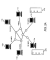
Figure 2A illustratesnodes 110e-j in thenetwork 100. Each of thenodes 110e-j measures a network metric, in this example bandwidth, to all the other nodes.Figure 2A shows the measured bandwidths, which are access bandwidth for each of the nodes. The access bandwidth is the transmission rate on the link closest to the node providing access to the network. In the examples shown infigures 2A-B , the lowest bandwidth of any path (i.e., the bandwidth of the bottleneck link in the path) happens to be the access bandwidth of one of the two end nodes of the path, and thus the minimum of the end nodes' access bandwidths may be considered as the bandwidth for the entire path. As shown infigure 2A , the access bandwidths for thenodes 110e-j are 100, 10, 50, 50, 1 and 100 Mbps, respectively. - The view of the network for the
node 110e, shown as 201 e, is the bandwidth for each of the paths from thenode 110e to thenodes 110f-i, respectively in this example. Theview 201 e includes 10, 50, 50, and 1 Mbps, which are the bandwidths for the paths between thenode 110e and thenodes 110f-i, respectively. Similarly, the view of the network for thenode 110j, shown as 201 j, includes 10, 50, 50, and 1 Mbps, which are the access bandwidths for thenodes 110f-i, respectively. Theview 201 j represents the bandwidth for each of the paths from thenode 110e to thenodes 110f-I, respectively. Theviews nodes -
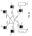
Figure 2B is an example of nodes that cannot be clustered. As shown infigure 2B , the view of the network for thenode 110e, shown as 201 e, includes 10, 50, 50, and 1 Mbps, as described above. Theview 201 k for thenode 110k is 1, 1, 1, 1 Mbps, which are the bandwidths for the paths between thenode 110k and thenodes 110f-i, respectively. The bandwidth is 1 Mbps for each path because that is the bandwidth of the bottleneck link of each path. Theviews nodes - The examples shown in
figures 2A-B are simplistic and it will be apparent to one of ordinary skill in the art that other metrics may be used to determine views of the network. Furthermore, views may not exactly match, but may still be considered close enough for placing the respective nodes in the same cluster. Criteria for comparing views to determine whether to place nodes in the same cluster are described in further detail below. - Through testing, it has been observed that many paths in a large network, such as the Internet, are shared. Also, most bottleneck links are in the first or last four hops in a path between a source and destination node. Also, tight and narrow links in a path are the same. A tight link is a link in a path with the smallest capacity. A narrow link is a link in a path with the smallest available bandwidth. Based on these observations, clustering approaches for determining available bandwidth for a path, according to embodiments, is described with respect to
figure 3 . -
Figure 3 illustrates a method for estimating available bandwidth using a clustering approach.Figure 3 is described with respect tofigures 1 and2A-B by way of example and not limitation. - At
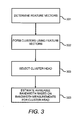
step 301, feature vectors are determined for each node. Theviews views figures 2A-B are examples of feature vectors and the network metric is bandwidth for those feature vectors. - In one embodiment, the feature vectors include capacity measurements. For example, the nodes 10e-j shown in
figure 2A each measure capacity to each other to determine feature vectors for each of the nodes. Bandwidth and capacity measurement tools known in the art may be used to perform the measurements. - Capacity measurements create network traffic. However, capacity is a relatively stable network metric and is typically valid for a much longer period of time, when compared to other metrics, such as available bandwidth, which are dependent on current network traffic. Thus, the periodicity of performing capacity measurements for feature vectors to be used for determining available bandwidth is less. Furthermore, since it has been observed that tight and narrow links in a path tend to be the same, capacity may be leveraged to determine available bandwidth for a path.
- In another embodiment, the feature vectors include the last m-hops for each path. For example, each of the nodes 10e-j shown in
figure 2A perform traceroutes to each other. The traceroutes are used to determine the last m-hops for each path between each of thenodes 110e-j. For example, if m=4, the feature vector for thenode 110e includes the last 4 hops in each path between thenode 110e and thenodes 110f-i. This may include a unique ID of the last four nodes in each path or some other representation of the last four nodes in each path. Since it has been observed that many paths in a large network are shared, nodes that are common for two different paths may be used as the metric for clustering. - At
step 302, the feature vectors are used to form clusters. Clusters are formed based on the "sameness" of the nodes view of the network in terms of a network metric, such as capacity, last hops in a path, etc. Sameness is determined from the feature vectors and distance metrics computed from the feature vectors as described below. - According to an embodiment, feature vectors are comprised of capacity measurements. Using the capacity measurements, a distance metric between any two given nodes in the network is computed to determine sameness between the nodes and to form clusters. For example, given a node pair and assuming n number of nodes are in the network, the distance metric is the average of the normalized differences between the capacity from the first node in the pair and the capacity from the second node in the pair to each other (n-2) nodes. For example, two nodes, such as the
node 110e and thenode 110j, shown infigure 2A , are being compared. Assuming thenetwork 100 includes n number of nodes, the average of the normalized differences between the capacity fromnode 110e and the capacity from thenode 110j to each of the other (n-2) nodes is computed. This computation is performed for every node pair. The result for each computation, for example, is a number between 0 and 1. Depending on where the threshold is set, the pair is either placed in the same cluster or not. Alternatively, the computation results are used as input to a known clustering function, such as k-means clustering, and the function determines the clusters. - Computing the distance metric for each pair of nodes is as follows: given n number of nodes in the network, a computation is performed for each node pair (i, j). At
step 301, for example, capacity is measured from each of the nodes i and j to every other node in the network to determine the feature vectors. A capacity measurement from the node i to a node k is represented as Cap(Ni,k), and Cap(Nj,k) represents the capacity measurement from the node j to node k in the network. A difference is computed. The difference is the capacity from node i to node k minus the capacity from node j to node k. The difference is divided by the maximum of the capacities from node i to node k and from node j to node k. This computation is represented by Equation 2 as follows: -

- The difference calculated in equation 2 is averaged across all other (n-2) nodes in the network. Thus, equation 2 is calculated for each node k, where k represents the nodes in the network othen than the nodes i and j. The number of nodes k is (n-2). The computation for averaging the differences across all other (n-2) nodes is shown in Equation 3 as follows:
-

- The normalized difference calculated in Equation 3, for example, is a number between 0 and 1 and is the distance metric for the pair. If the capacities are the same, then the difference is 0 and then the nodes i and j have the same view and are placed in the same cluster. Generally, if the normalized difference is closer to 0, the nodes are placed in the same cluster. If the normalized difference is closer to 1, the nodes are not placed in the same cluster. In one embodiment, the results of Equation 3 for each node pair in the network are used as input to a known clustering function, such as k-means clustering, and the function determines the clusters.
- The distance metric may be calculated for a subset of nodes in the network instead of all the nodes in the network. For example, n is a number of nodes in the subset of nodes in the network; (n-2) is a number of the nodes in the subset except for the node pair; and k represents each node in the subset.
- According to another embodiment, paths are used to determine feature vectors. For example, as described above, the last m-hops to all destination nodes are provided in the feature vectors for each node. A distance metric representing path similarity is calculated, which measures the fraction of nodes that are common between the routes from two nodes in a node pair to a common destination and averages over all destinations. Any standard clustering technique may then be applied to obtain the clusters. A distance metric of 1 implies nodes can be clustered and a distance metric of 0 implies nodes cannot be clustered.
- Computing the distance metric for each pair of node is as follows: given n number of nodes in the network, a computation is performed for each pair of source nodes i and j. and a destination node k. At
step 301, for example, the last m-hops are determined for the two paths between nodes i and k and nodes j and k. For each of the hops h ranging from 1 to m, a hop similarity function


-

- For example, for m=4, in computing the feature vector for a node i, the intermediate nodes at the last 4 hops (h0, h1, h2, h3) to each destination node k are used. Assume that the last four hops from node i to the node k are 110h, 110i, 110j and 110k, and the last four hops from node j to the node k is 110h, 110i, 110x, 110y. The results of equation 4 for nodes i and j with respect to destination k is 1, 1, 0, and 0, because h0 and h1 are the same in both feature vectors and h2 and h3 are different.
- The path similarity (PS) of two paths from node i to k and node j to k is computed as a function of the sum of

-

- In the example above where the last four hops from node i to the node k are 110h, 110i, 110j and 110k and the last four hops from node j to the node k are 110h, 110i, 110x, 110y, the result of equation 5 is 2/4.
- PSi,j is averaged over the set of all other destination nodes k, such that k ≠ i, j. The normalized PS is the distance metric and is calculated using Equation 6:
-

- Thus, at
step 302, a distance metric matrix including the distance metric for every node pair is created. If a known clustering function, such as k-means clustering function, is used to form the clusters, the distance matrix metric along with the number of clusters to be formed is input into the clustering function to form the clusters of nodes. - At
step 303, a cluster head is selected for each cluster. For example, once the clusters are created, each cluster elects its cluster representative, i.e., the cluster head, which then conducts bandwidth measurements to the nodes outside the cluster. The cluster representative may be chosen by a number of techniques. - In a direct approach for determining the cluster head, the cluster head is chosen, for example randomly, and available bandwidth measurements from the cluster head are considered estimations from all the nodes in the cluster.
- Available bandwidth measurements are also performed to obtain the bandwidths between the nodes inside each cluster. These measurements may be used to identify a bottleneck link close to the source and for selecting a cluster head using a second approach, referred to as the min-use approach. In this approach, if available bandwidth between a node in the cluster, referred to as a source node in the cluster, and the cluster head is less than the available bandwidth between the cluster head and a node outside the cluster, referred to as a destination node outside the cluster, the available bandwidth between the source node in the cluster and the cluster head is used as the estimation of available bandwidth between the source node and that destination node. The min-use approach accounts for bottleneck links that may be closer to the source node rather than the destination node. These bottleneck links may be used as the estimation of available bandwidth from the nodes in the cluster. If the bandwidths between the cluster head and the nodes outside the cluster are smaller than the bandwidths between the nodes in the cluster and the cluster head, the bottleneck links may be close to the destination. Then, the bandwidths between the cluster head and the nodes outside the cluster may be used as the estimation of available bandwidth for the nodes in the cluster.
- For example,
nodes node 110e is selected as the cluster head using the direct approach. Thenode 110e measures available bandwidths to all the nodes outside the cluster. Assume the node is 110g is outside the cluster. If the available bandwidth between 110e and 110g is 10Mbps and the available bandwidth between 110e and 110j is 5 Mbps, then 5 Mbps may be used as the available bandwidth to thedestination 110g fromnode 110j. If the available bandwidth between another node in the cluster and 110e is less than 5 Mbps, then that available bandwidth may be used as the available bandwidth to thedestination 110g from that node. - At step 304, available bandwidth measurements from a single node in the cluster are used as an estimation of available bandwidth from all the nodes in the cluster.
-
Figure 4 illustrates an exemplary block diagram of acomputer system 400 that may be used as a node in thenetwork 100. Thecomputer system 400 includes one or more processors, such asprocessor 402, providing an execution platform for executing software. - Commands and data from the
processor 402 are communicated over acommunication bus 405. Thecomputer system 400 also includes amain memory 404, such as a Random Access Memory (RAM), where software may be resident during runtime, and asecondary memory 406. Thesecondary memory 406 includes, for example, a hard disk drive and/or a removable storage drive, representing a floppy diskette drive, a magnetic tape drive, a compact disk drive, etc., or a nonvolatile memory where a copy of the software may be stored. Thesecondary memory 406 may also include ROM (read only memory), EPROM (erasable, programmable ROM), EEPROM (electrically erasable, programmable ROM). In addition to software for routing and other steps described herein, routing tables, capacities for overlay paths, available bandwidths for overlay paths, and other data may be stored in themain memory 404 and/or thesecondary memory 406. Thememories 404 and/or 406 may store network metric measurements, including feature vectors and measured available bandwidths. - A user interfaces with the
computer system 400 with one or more I/O devices 404, such as a keyboard, a mouse, a stylus, display, and the like. Anetwork interface 416 is provided for communicating with other nodes in thenetwork 100. - One or more of the steps of the method 300 and other steps described herein may be implemented as software embedded on a computer readable medium, such as the
memory 404 and/or 406, and executed on thecomputer system 400, for example, by theprocessor 402. The steps may be embodied by a computer program, which may exist in a variety of forms both active and inactive. For example, they may exist as software program(s) comprised of program instructions in source code, object code, executable code or other formats for performing some of the steps. Any of the above may be embodied on a computer readable medium, which include storage devices and signals, in compressed or uncompressed form. Examples of suitable computer readable storage devices include conventional computer system RAM (random access memory), ROM (read only memory), EPROM (erasable, programmable ROM), EEPROM (electrically erasable, programmable ROM), and magnetic or optical disks or tapes. Examples of computer readable signals, whether modulated using a carrier or not, are signals that a computer system hosting or running the computer program may be configured to access, including signals downloaded through the Internet or other networks. Concrete examples of the foregoing include distribution of the programs on a CD ROM or via Internet download. In a sense, the Internet itself, as an abstract entity, is a computer readable medium. The same is true of computer networks in general. It is therefore to be understood that those functions enumerated below may be performed by any electronic device capable of executing the above-described functions. - While the embodiments have been described with reference to examples, those skilled in the art will be able to make various modifications to the described embodiments without departing from the scope of the claimed embodiments.
Claims (10)
- A method of estimating available bandwidth between nodes (110) in a network (100), the method comprising:determining (301) feature vectors for each node based on a network metric;determining (302) one or more clusters of the nodes based on the feature vectors;selecting (303) a cluster head for each cluster;for each cluster, determining an available first bandwidth between the cluster head and a designation node outside the cluster;for each cluster, determining an available second bandwidth between the cluster head and a source node inside the cluster;if the available first bandwidth is less than the available second bandwidth, using the bandwidth between the source node in the cluster and the cluster head as the estimation of available bandwidth between the source node and that destination node; andif the available second bandwidth is smaller than the available first bandwidth, using the bandwidth between the cluster head and the designation node outside the cluster as the estimation of available bandwidth for the nodes in the cluster.
- The method of claim 1, wherein determining feature vectors comprises:measuring capacity from each node to every other node in the network (100) to determine the feature vectors.
- The method of claim 1, wherein determining feature vectors comprises:determining a number of last hops in paths between each node and every other node in the network (100) to determine the feature vectors.
- The method of claim 1, wherein determining clusters of the nodes based on the feature vectors comprises:for every pair of the nodes, determining a sameness of the nodes based on the network metric; andplacing each pair of the nodes in the same cluster based on the sameness.
- The method of claim 4, wherein determining a sameness comprises:computing a distance metric from the feature vectors for each pair of nodes; anddetermining the sameness for the pair of nodes based on the distance metric.
- The method of claim 5, wherein determining clusters comprises:using the distance metrics for all the node pairs as input to a clustering function to determine the clusters.
- The method of claim 5, wherein the feature vectors comprise capacity measurements, every node pair is represented by (i, j) and there are n nodes in the network, and computing the distance metric comprises:for each pair of nodes computing an average of a normalized difference between the capacity from node i and from node j to each one of other (n-2) nodes.
- The method of claim 5, wherein the feature vectors comprise a number of last hops to all destination nodes, every node pair is represented by (i, j) and there are n nodes in the network, computing the distance metric comprises:for each pair of nodes computing a value indicative of a fraction of nodes that are common between the routes from nodes i and j to all other nodes in the network; and averaging the values over n-2.
- A node of a plurality of nodes in a cluster, wherein the node is a cluster head of the cluster and the plurality of nodes are in a network (100), the node comprising:a memory (404) storing available bandwidth measurements between the node and nodes in the network (100) outside the cluster; anda processor (402) operable todetermine an available first bandwidth between the node and a designation node outside the cluster;determine an available second bandwidth between the node and a source node inside the cluster;if the available first bandwidth is less than the available second bandwidth, using the bandwidth between the source node in the cluster and the node as the estimation of available bandwidth between the source node and that destination node; andif the available second bandwidth is smaller than the available first bandwidth, using the bandwidth between the node and the designation node outside the cluster as the estimation of available bandwidth for the nodes in the cluster.
- The node of claim 9, wherein the memory (404) stores a feature vector of network metric values, and the network metric values are associated with network paths between the node and other nodes in the network (100), wherein the node is placed in a same cluster as all other nodes in the plurality of nodes based on a comparison of the feature vector for the node and the feature vectors for all the other nodes in the plurality of nodes in the cluster.
Applications Claiming Priority (2)
| Application Number | Priority Date | Filing Date | Title |
|---|---|---|---|
| US11/787,008 US7813351B2 (en) | 2007-04-13 | 2007-04-13 | Available bandwidth estimation |
| PCT/US2008/004424 WO2008127574A1 (en) | 2007-04-13 | 2008-04-02 | Available bandwidth estimation |
Publications (3)
| Publication Number | Publication Date |
|---|---|
| EP2137888A1 EP2137888A1 (en) | 2009-12-30 |
| EP2137888A4 EP2137888A4 (en) | 2012-02-22 |
| EP2137888B1 true EP2137888B1 (en) | 2013-08-21 |
Family
ID=39853606
Family Applications (1)
| Application Number | Title | Priority Date | Filing Date |
|---|---|---|---|
| EP08742575.7A Not-in-force EP2137888B1 (en) | 2007-04-13 | 2008-04-02 | Available bandwidth estimation |
Country Status (4)
| Country | Link |
|---|---|
| US (1) | US7813351B2 (en) |
| EP (1) | EP2137888B1 (en) |
| CN (1) | CN101682548B (en) |
| WO (1) | WO2008127574A1 (en) |
Families Citing this family (17)
| Publication number | Priority date | Publication date | Assignee | Title |
|---|---|---|---|---|
| US8275866B2 (en) * | 2007-11-13 | 2012-09-25 | At&T Intellectual Property I, L.P. | Assigning telecommunications nodes to community of interest clusters |
| US8315164B2 (en) * | 2008-12-11 | 2012-11-20 | Skype | Controlling packet transmission |
| GB2466208B (en) | 2008-12-11 | 2013-09-11 | Skype | Controlling packet transmission |
| IL216207A (en) * | 2011-11-08 | 2017-05-29 | Google Inc | Splitting a network traffic flow |
| JP2014044677A (en) * | 2012-08-28 | 2014-03-13 | Fujitsu Ltd | Transmission control program, communication node, and transmission control method |
| US9680915B2 (en) * | 2012-09-12 | 2017-06-13 | Infosys Limited | Methods for clustering networks based on topology discovery and devices thereof |
| US9231843B2 (en) | 2012-11-29 | 2016-01-05 | International Business Machines Corporation | Estimating available bandwith in cellular networks |
| WO2015000107A1 (en) * | 2013-07-01 | 2015-01-08 | Empire Technology Development Llc | Formation of guilds in a cloud computing environment |
| US9781610B2 (en) * | 2013-12-18 | 2017-10-03 | Qualcomm Incorporated | Small cell clusters for signaling load reduction, time synchronization, KPI filtering and spectrum coordination |
| DE102014103702B4 (en) * | 2014-03-18 | 2017-08-03 | Intel IP Corporation | Method and apparatus for processing resource blocks |
| US9338714B2 (en) * | 2014-04-24 | 2016-05-10 | United States Cellular Corporation | System and method for providing mobile wireless data network connectivity via vehicle-installed small cell |
| US10225761B2 (en) | 2014-11-06 | 2019-03-05 | At&T Intellectual Property I, L.P. | Enhanced network congestion application programming interface |
| CN105490873B (en) * | 2015-11-25 | 2019-01-11 | 上海大学 | The available network bandwidth measurement method of expansion attack can be resisted |
| CN105897582A (en) * | 2015-12-07 | 2016-08-24 | 乐视云计算有限公司 | Inter-node distance measurement method and system |
| US10069689B1 (en) * | 2015-12-18 | 2018-09-04 | Amazon Technologies, Inc. | Cache based on dynamic device clustering |
| CN109165322B (en) * | 2018-08-01 | 2022-04-19 | 成都数联铭品科技有限公司 | Network feature extraction system and method based on path relation |
| CN115567450A (en) | 2019-09-06 | 2023-01-03 | 华为技术有限公司 | a network device |
Family Cites Families (13)
| Publication number | Priority date | Publication date | Assignee | Title |
|---|---|---|---|---|
| US5758257A (en) * | 1994-11-29 | 1998-05-26 | Herz; Frederick | System and method for scheduling broadcast of and access to video programs and other data using customer profiles |
| US6920171B2 (en) * | 2000-12-14 | 2005-07-19 | Motorola, Inc. | Multiple access frequency hopping network with interference anticipation |
| US7764617B2 (en) * | 2002-04-29 | 2010-07-27 | Harris Corporation | Mobile ad-hoc network and methods for performing functions therein based upon weighted quality of service metrics |
| US7281057B2 (en) * | 2002-04-29 | 2007-10-09 | Harris Corporation | Hierarchical mobile ad-hoc network and methods for performing reactive routing therein |
| US7729268B2 (en) * | 2002-06-28 | 2010-06-01 | Ntt Docomo, Inc. | Method and apparatus for quality of service determination |
| US20040059830A1 (en) * | 2002-09-17 | 2004-03-25 | Sockeye Networks, Inc. | Network address space clustering employing topological groupings, distance measurements and structural generalization |
| US20050002372A1 (en) * | 2003-06-13 | 2005-01-06 | Johan Rune | Method of and system for intra-piconet scheduling |
| US7706282B2 (en) * | 2003-06-25 | 2010-04-27 | Leping Huang | Bluetooth personal area network routing protocol optimization using connectivity metric |
| US7975035B2 (en) * | 2003-12-01 | 2011-07-05 | International Business Machines Corporation | Method and apparatus to support application and network awareness of collaborative applications using multi-attribute clustering |
| TWI234970B (en) * | 2003-12-05 | 2005-06-21 | Inst Information Industry | Method and system for route selection and method for route reconstruction |
| CN100518055C (en) * | 2003-12-10 | 2009-07-22 | 联想(北京)有限公司 | A Safe Data Transmission Method |
| US7978710B2 (en) * | 2004-03-26 | 2011-07-12 | Qualcomm Incorporated | Synchronous inter-piconet routing |
| US20070160016A1 (en) * | 2006-01-09 | 2007-07-12 | Amit Jain | System and method for clustering wireless devices in a wireless network |
-
2007
- 2007-04-13 US US11/787,008 patent/US7813351B2/en not_active Expired - Fee Related
-
2008
- 2008-04-02 WO PCT/US2008/004424 patent/WO2008127574A1/en not_active Ceased
- 2008-04-02 EP EP08742575.7A patent/EP2137888B1/en not_active Not-in-force
- 2008-04-02 CN CN200880020035.4A patent/CN101682548B/en not_active Expired - Fee Related
Also Published As
| Publication number | Publication date |
|---|---|
| EP2137888A4 (en) | 2012-02-22 |
| CN101682548A (en) | 2010-03-24 |
| EP2137888A1 (en) | 2009-12-30 |
| CN101682548B (en) | 2013-06-19 |
| US20080253286A1 (en) | 2008-10-16 |
| US7813351B2 (en) | 2010-10-12 |
| WO2008127574A1 (en) | 2008-10-23 |
Similar Documents
| Publication | Publication Date | Title |
|---|---|---|
| EP2137888B1 (en) | Available bandwidth estimation | |
| US9420513B1 (en) | Clustering approach to estimating a network metric for nodes | |
| US7643426B1 (en) | Path selection in a network | |
| US10924388B1 (en) | Multi-path routing | |
| JP4226922B2 (en) | Peer-to-peer based network performance measurement and analysis system and method for large networks | |
| EP1719308B1 (en) | Selecting nodes close to another node in a network using location information for the nodes | |
| US7483391B2 (en) | Providing a notification including location information for nodes in an overlay network | |
| US7788400B2 (en) | Utilizing proximity information in an overlay network | |
| US6947386B2 (en) | Practical network node coordinate estimation | |
| US7644167B2 (en) | Identifying a service node in a network | |
| US7839840B2 (en) | Method and system for routing traffic in a communication network | |
| CN101854299A (en) | A Dynamic Load Balancing Method for Publish/Subscribe System | |
| CN106664220B (en) | Estimating bandwidth in a network | |
| US20060120411A1 (en) | Splitting a workload of a node | |
| US7965655B2 (en) | Distributed network distance determination using a distributed hash table overlay network | |
| Lou et al. | Boosting or hindering: AoI and throughput interrelation in routing-aware multi-hop wireless networks | |
| Alghamdi | Stable zone-based 5G clustered MANET using interest-region-based routing and gateway selection | |
| Sakellari | The cognitive packet network: A survey | |
| EP1825654B1 (en) | Routing a service query in an overlay network | |
| JP4854078B2 (en) | Method, system, and program for generating an annotated network topology | |
| US8660018B2 (en) | Machine learning approach for estimating a network path property | |
| US10623306B2 (en) | Multi-path routing | |
| US7636325B2 (en) | Determining highest workloads for nodes in an overlay network | |
| Li et al. | MPTCP-based link congestion detection and traffic control scheme in software-defined networks | |
| US9860159B1 (en) | Multi-path routing |
Legal Events
| Date | Code | Title | Description |
|---|---|---|---|
| PUAI | Public reference made under article 153(3) epc to a published international application that has entered the european phase |
Free format text: ORIGINAL CODE: 0009012 |
|
| 17P | Request for examination filed |
Effective date: 20091009 |
|
| AK | Designated contracting states |
Kind code of ref document: A1 Designated state(s): AT BE BG CH CY CZ DE DK EE ES FI FR GB GR HR HU IE IS IT LI LT LU LV MC MT NL NO PL PT RO SE SI SK TR |
|
| RIN1 | Information on inventor provided before grant (corrected) |
Inventor name: YALAGANDULA, PRAVEEN Inventor name: SHRIRAM, ALOK Inventor name: LEE, SUNG-JU Inventor name: BANERJEE, SUJATA |
|
| DAX | Request for extension of the european patent (deleted) | ||
| A4 | Supplementary search report drawn up and despatched |
Effective date: 20120123 |
|
| RIC1 | Information provided on ipc code assigned before grant |
Ipc: H04L 12/26 20060101ALI20120117BHEP Ipc: H04L 12/24 20060101ALI20120117BHEP Ipc: H04L 12/56 20060101ALI20120117BHEP Ipc: H04L 12/28 20060101AFI20120117BHEP |
|
| 17Q | First examination report despatched |
Effective date: 20121008 |
|
| GRAP | Despatch of communication of intention to grant a patent |
Free format text: ORIGINAL CODE: EPIDOSNIGR1 |
|
| REG | Reference to a national code |
Ref country code: DE Ref legal event code: R079 Ref document number: 602008026981 Country of ref document: DE Free format text: PREVIOUS MAIN CLASS: H04L0012280000 Ipc: H04L0012729000 |
|
| RIC1 | Information provided on ipc code assigned before grant |
Ipc: H04L 12/721 20130101ALI20130311BHEP Ipc: H04L 12/725 20130101ALI20130311BHEP Ipc: H04L 12/715 20130101ALI20130311BHEP Ipc: H04L 12/729 20130101AFI20130311BHEP Ipc: H04L 12/801 20130101ALI20130311BHEP |
|
| GRAS | Grant fee paid |
Free format text: ORIGINAL CODE: EPIDOSNIGR3 |
|
| GRAA | (expected) grant |
Free format text: ORIGINAL CODE: 0009210 |
|
| AK | Designated contracting states |
Kind code of ref document: B1 Designated state(s): AT BE BG CH CY CZ DE DK EE ES FI FR GB GR HR HU IE IS IT LI LT LU LV MC MT NL NO PL PT RO SE SI SK TR |
|
| REG | Reference to a national code |
Ref country code: GB Ref legal event code: FG4D |
|
| REG | Reference to a national code |
Ref country code: CH Ref legal event code: EP |
|
| REG | Reference to a national code |
Ref country code: AT Ref legal event code: REF Ref document number: 628649 Country of ref document: AT Kind code of ref document: T Effective date: 20130915 |
|
| REG | Reference to a national code |
Ref country code: IE Ref legal event code: FG4D |
|
| REG | Reference to a national code |
Ref country code: DE Ref legal event code: R096 Ref document number: 602008026981 Country of ref document: DE Effective date: 20131017 |
|
| REG | Reference to a national code |
Ref country code: AT Ref legal event code: MK05 Ref document number: 628649 Country of ref document: AT Kind code of ref document: T Effective date: 20130821 Ref country code: NL Ref legal event code: VDEP Effective date: 20130821 |
|
| REG | Reference to a national code |
Ref country code: LT Ref legal event code: MG4D |
|
| PG25 | Lapsed in a contracting state [announced via postgrant information from national office to epo] |
Ref country code: SE Free format text: LAPSE BECAUSE OF FAILURE TO SUBMIT A TRANSLATION OF THE DESCRIPTION OR TO PAY THE FEE WITHIN THE PRESCRIBED TIME-LIMIT Effective date: 20130821 Ref country code: HR Free format text: LAPSE BECAUSE OF FAILURE TO SUBMIT A TRANSLATION OF THE DESCRIPTION OR TO PAY THE FEE WITHIN THE PRESCRIBED TIME-LIMIT Effective date: 20130821 Ref country code: PT Free format text: LAPSE BECAUSE OF FAILURE TO SUBMIT A TRANSLATION OF THE DESCRIPTION OR TO PAY THE FEE WITHIN THE PRESCRIBED TIME-LIMIT Effective date: 20131223 Ref country code: LT Free format text: LAPSE BECAUSE OF FAILURE TO SUBMIT A TRANSLATION OF THE DESCRIPTION OR TO PAY THE FEE WITHIN THE PRESCRIBED TIME-LIMIT Effective date: 20130821 Ref country code: NO Free format text: LAPSE BECAUSE OF FAILURE TO SUBMIT A TRANSLATION OF THE DESCRIPTION OR TO PAY THE FEE WITHIN THE PRESCRIBED TIME-LIMIT Effective date: 20131121 Ref country code: IS Free format text: LAPSE BECAUSE OF FAILURE TO SUBMIT A TRANSLATION OF THE DESCRIPTION OR TO PAY THE FEE WITHIN THE PRESCRIBED TIME-LIMIT Effective date: 20131221 Ref country code: AT Free format text: LAPSE BECAUSE OF FAILURE TO SUBMIT A TRANSLATION OF THE DESCRIPTION OR TO PAY THE FEE WITHIN THE PRESCRIBED TIME-LIMIT Effective date: 20130821 Ref country code: CY Free format text: LAPSE BECAUSE OF FAILURE TO SUBMIT A TRANSLATION OF THE DESCRIPTION OR TO PAY THE FEE WITHIN THE PRESCRIBED TIME-LIMIT Effective date: 20130814 |
|
| PG25 | Lapsed in a contracting state [announced via postgrant information from national office to epo] |
Ref country code: LV Free format text: LAPSE BECAUSE OF FAILURE TO SUBMIT A TRANSLATION OF THE DESCRIPTION OR TO PAY THE FEE WITHIN THE PRESCRIBED TIME-LIMIT Effective date: 20130821 Ref country code: BE Free format text: LAPSE BECAUSE OF FAILURE TO SUBMIT A TRANSLATION OF THE DESCRIPTION OR TO PAY THE FEE WITHIN THE PRESCRIBED TIME-LIMIT Effective date: 20130821 Ref country code: FI Free format text: LAPSE BECAUSE OF FAILURE TO SUBMIT A TRANSLATION OF THE DESCRIPTION OR TO PAY THE FEE WITHIN THE PRESCRIBED TIME-LIMIT Effective date: 20130821 Ref country code: PL Free format text: LAPSE BECAUSE OF FAILURE TO SUBMIT A TRANSLATION OF THE DESCRIPTION OR TO PAY THE FEE WITHIN THE PRESCRIBED TIME-LIMIT Effective date: 20130821 Ref country code: GR Free format text: LAPSE BECAUSE OF FAILURE TO SUBMIT A TRANSLATION OF THE DESCRIPTION OR TO PAY THE FEE WITHIN THE PRESCRIBED TIME-LIMIT Effective date: 20131122 Ref country code: SI Free format text: LAPSE BECAUSE OF FAILURE TO SUBMIT A TRANSLATION OF THE DESCRIPTION OR TO PAY THE FEE WITHIN THE PRESCRIBED TIME-LIMIT Effective date: 20130821 |
|
| PG25 | Lapsed in a contracting state [announced via postgrant information from national office to epo] |
Ref country code: CY Free format text: LAPSE BECAUSE OF FAILURE TO SUBMIT A TRANSLATION OF THE DESCRIPTION OR TO PAY THE FEE WITHIN THE PRESCRIBED TIME-LIMIT Effective date: 20130821 |
|
| PG25 | Lapsed in a contracting state [announced via postgrant information from national office to epo] |
Ref country code: DK Free format text: LAPSE BECAUSE OF FAILURE TO SUBMIT A TRANSLATION OF THE DESCRIPTION OR TO PAY THE FEE WITHIN THE PRESCRIBED TIME-LIMIT Effective date: 20130821 Ref country code: RO Free format text: LAPSE BECAUSE OF FAILURE TO SUBMIT A TRANSLATION OF THE DESCRIPTION OR TO PAY THE FEE WITHIN THE PRESCRIBED TIME-LIMIT Effective date: 20130821 Ref country code: EE Free format text: LAPSE BECAUSE OF FAILURE TO SUBMIT A TRANSLATION OF THE DESCRIPTION OR TO PAY THE FEE WITHIN THE PRESCRIBED TIME-LIMIT Effective date: 20130821 Ref country code: NL Free format text: LAPSE BECAUSE OF FAILURE TO SUBMIT A TRANSLATION OF THE DESCRIPTION OR TO PAY THE FEE WITHIN THE PRESCRIBED TIME-LIMIT Effective date: 20130821 Ref country code: CZ Free format text: LAPSE BECAUSE OF FAILURE TO SUBMIT A TRANSLATION OF THE DESCRIPTION OR TO PAY THE FEE WITHIN THE PRESCRIBED TIME-LIMIT Effective date: 20130821 Ref country code: SK Free format text: LAPSE BECAUSE OF FAILURE TO SUBMIT A TRANSLATION OF THE DESCRIPTION OR TO PAY THE FEE WITHIN THE PRESCRIBED TIME-LIMIT Effective date: 20130821 |
|
| PG25 | Lapsed in a contracting state [announced via postgrant information from national office to epo] |
Ref country code: ES Free format text: LAPSE BECAUSE OF FAILURE TO SUBMIT A TRANSLATION OF THE DESCRIPTION OR TO PAY THE FEE WITHIN THE PRESCRIBED TIME-LIMIT Effective date: 20130821 Ref country code: IT Free format text: LAPSE BECAUSE OF FAILURE TO SUBMIT A TRANSLATION OF THE DESCRIPTION OR TO PAY THE FEE WITHIN THE PRESCRIBED TIME-LIMIT Effective date: 20130821 |
|
| PLBE | No opposition filed within time limit |
Free format text: ORIGINAL CODE: 0009261 |
|
| STAA | Information on the status of an ep patent application or granted ep patent |
Free format text: STATUS: NO OPPOSITION FILED WITHIN TIME LIMIT |
|
| 26N | No opposition filed |
Effective date: 20140522 |
|
| REG | Reference to a national code |
Ref country code: DE Ref legal event code: R097 Ref document number: 602008026981 Country of ref document: DE Effective date: 20140522 |
|
| PG25 | Lapsed in a contracting state [announced via postgrant information from national office to epo] |
Ref country code: LU Free format text: LAPSE BECAUSE OF FAILURE TO SUBMIT A TRANSLATION OF THE DESCRIPTION OR TO PAY THE FEE WITHIN THE PRESCRIBED TIME-LIMIT Effective date: 20140402 Ref country code: MC Free format text: LAPSE BECAUSE OF FAILURE TO SUBMIT A TRANSLATION OF THE DESCRIPTION OR TO PAY THE FEE WITHIN THE PRESCRIBED TIME-LIMIT Effective date: 20130821 |
|
| REG | Reference to a national code |
Ref country code: CH Ref legal event code: PL |
|
| REG | Reference to a national code |
Ref country code: IE Ref legal event code: MM4A |
|
| PG25 | Lapsed in a contracting state [announced via postgrant information from national office to epo] |
Ref country code: CH Free format text: LAPSE BECAUSE OF NON-PAYMENT OF DUE FEES Effective date: 20140430 Ref country code: LI Free format text: LAPSE BECAUSE OF NON-PAYMENT OF DUE FEES Effective date: 20140430 |
|
| PG25 | Lapsed in a contracting state [announced via postgrant information from national office to epo] |
Ref country code: IE Free format text: LAPSE BECAUSE OF NON-PAYMENT OF DUE FEES Effective date: 20140402 |
|
| REG | Reference to a national code |
Ref country code: FR Ref legal event code: PLFP Year of fee payment: 9 |
|
| PG25 | Lapsed in a contracting state [announced via postgrant information from national office to epo] |
Ref country code: MT Free format text: LAPSE BECAUSE OF FAILURE TO SUBMIT A TRANSLATION OF THE DESCRIPTION OR TO PAY THE FEE WITHIN THE PRESCRIBED TIME-LIMIT Effective date: 20130821 |
|
| PG25 | Lapsed in a contracting state [announced via postgrant information from national office to epo] |
Ref country code: BG Free format text: LAPSE BECAUSE OF FAILURE TO SUBMIT A TRANSLATION OF THE DESCRIPTION OR TO PAY THE FEE WITHIN THE PRESCRIBED TIME-LIMIT Effective date: 20130821 |
|
| REG | Reference to a national code |
Ref country code: DE Ref legal event code: R082 Ref document number: 602008026981 Country of ref document: DE Representative=s name: SCHOPPE, ZIMMERMANN, STOECKELER, ZINKLER, SCHE, DE Ref country code: DE Ref legal event code: R081 Ref document number: 602008026981 Country of ref document: DE Owner name: HEWLETT PACKARD ENTERPRISE DEVELOPMENT LP, HOU, US Free format text: FORMER OWNER: HEWLETT-PACKARD DEVELOPMENT COMPANY, L.P., HOUSTON, TEX., US |
|
| REG | Reference to a national code |
Ref country code: GB Ref legal event code: 732E Free format text: REGISTERED BETWEEN 20160701 AND 20160706 |
|
| PG25 | Lapsed in a contracting state [announced via postgrant information from national office to epo] |
Ref country code: HU Free format text: LAPSE BECAUSE OF FAILURE TO SUBMIT A TRANSLATION OF THE DESCRIPTION OR TO PAY THE FEE WITHIN THE PRESCRIBED TIME-LIMIT; INVALID AB INITIO Effective date: 20080402 Ref country code: TR Free format text: LAPSE BECAUSE OF FAILURE TO SUBMIT A TRANSLATION OF THE DESCRIPTION OR TO PAY THE FEE WITHIN THE PRESCRIBED TIME-LIMIT Effective date: 20130821 |
|
| REG | Reference to a national code |
Ref country code: FR Ref legal event code: TP Owner name: HEWLETT PACKARD ENTREPRISE DEVELOPMENT LP, US Effective date: 20160819 |
|
| REG | Reference to a national code |
Ref country code: FR Ref legal event code: PLFP Year of fee payment: 10 |
|
| REG | Reference to a national code |
Ref country code: FR Ref legal event code: PLFP Year of fee payment: 11 |
|
| PGFP | Annual fee paid to national office [announced via postgrant information from national office to epo] |
Ref country code: FR Payment date: 20200319 Year of fee payment: 13 |
|
| REG | Reference to a national code |
Ref country code: DE Ref legal event code: R079 Ref document number: 602008026981 Country of ref document: DE Free format text: PREVIOUS MAIN CLASS: H04L0012729000 Ipc: H04L0045125000 |
|
| PG25 | Lapsed in a contracting state [announced via postgrant information from national office to epo] |
Ref country code: FR Free format text: LAPSE BECAUSE OF NON-PAYMENT OF DUE FEES Effective date: 20210430 |
|
| REG | Reference to a national code |
Ref country code: DE Ref legal event code: R082 Ref document number: 602008026981 Country of ref document: DE Representative=s name: FLEUCHAUS & GALLO PARTNERSCHAFT MBB - PATENT- , DE Ref country code: DE Ref legal event code: R082 Ref document number: 602008026981 Country of ref document: DE Representative=s name: FLEUCHAUS & GALLO PARTNERSCHAFT MBB PATENTANWA, DE |
|
| REG | Reference to a national code |
Ref country code: DE Ref legal event code: R081 Ref document number: 602008026981 Country of ref document: DE Owner name: HEWLETT PACKARD ENTERPRISE DEVELOPMENT LP, SPR, US Free format text: FORMER OWNER: HEWLETT PACKARD ENTERPRISE DEVELOPMENT LP, HOUSTON, TEX., US |
|
| PGFP | Annual fee paid to national office [announced via postgrant information from national office to epo] |
Ref country code: GB Payment date: 20240423 Year of fee payment: 17 |
|
| PGFP | Annual fee paid to national office [announced via postgrant information from national office to epo] |
Ref country code: DE Payment date: 20240429 Year of fee payment: 17 |
|
| REG | Reference to a national code |
Ref country code: DE Ref legal event code: R119 Ref document number: 602008026981 Country of ref document: DE |
|
| GBPC | Gb: european patent ceased through non-payment of renewal fee |
Effective date: 20250402 |
|
| PG25 | Lapsed in a contracting state [announced via postgrant information from national office to epo] |
Ref country code: DE Free format text: LAPSE BECAUSE OF NON-PAYMENT OF DUE FEES Effective date: 20251104 |
|
| PG25 | Lapsed in a contracting state [announced via postgrant information from national office to epo] |
Ref country code: GB Free format text: LAPSE BECAUSE OF NON-PAYMENT OF DUE FEES Effective date: 20250402 |