EP2137586B1 - Pressure control for vacuum processing system - Google Patents
Pressure control for vacuum processing system Download PDFInfo
- Publication number
- EP2137586B1 EP2137586B1 EP20080731208 EP08731208A EP2137586B1 EP 2137586 B1 EP2137586 B1 EP 2137586B1 EP 20080731208 EP20080731208 EP 20080731208 EP 08731208 A EP08731208 A EP 08731208A EP 2137586 B1 EP2137586 B1 EP 2137586B1
- Authority
- EP
- European Patent Office
- Prior art keywords
- pressure
- tool
- controller
- communication network
- sensor
- Prior art date
- Legal status (The legal status is an assumption and is not a legal conclusion. Google has not performed a legal analysis and makes no representation as to the accuracy of the status listed.)
- Not-in-force
Links
Images

Classifications
-
- G—PHYSICS
- G05—CONTROLLING; REGULATING
- G05D—SYSTEMS FOR CONTROLLING OR REGULATING NON-ELECTRIC VARIABLES
- G05D16/00—Control of fluid pressure
- G05D16/20—Control of fluid pressure characterised by the use of electric means
-
- G—PHYSICS
- G05—CONTROLLING; REGULATING
- G05D—SYSTEMS FOR CONTROLLING OR REGULATING NON-ELECTRIC VARIABLES
- G05D16/00—Control of fluid pressure
- G05D16/20—Control of fluid pressure characterised by the use of electric means
- G05D16/2006—Control of fluid pressure characterised by the use of electric means with direct action of electric energy on controlling means
- G05D16/2013—Control of fluid pressure characterised by the use of electric means with direct action of electric energy on controlling means using throttling means as controlling means
-
- H—ELECTRICITY
- H04—ELECTRIC COMMUNICATION TECHNIQUE
- H04L—TRANSMISSION OF DIGITAL INFORMATION, e.g. TELEGRAPHIC COMMUNICATION
- H04L12/00—Data switching networks
- H04L12/28—Data switching networks characterised by path configuration, e.g. LAN [Local Area Networks] or WAN [Wide Area Networks]
-
- H—ELECTRICITY
- H10—SEMICONDUCTOR DEVICES; ELECTRIC SOLID-STATE DEVICES NOT OTHERWISE PROVIDED FOR
- H10P—GENERIC PROCESSES OR APPARATUS FOR THE MANUFACTURE OR TREATMENT OF DEVICES COVERED BY CLASS H10
- H10P72/00—Handling or holding of wafers, substrates or devices during manufacture or treatment thereof
- H10P72/06—Apparatus for monitoring, sorting, marking, testing or measuring
- H10P72/0604—Process monitoring, e.g. flow or thickness monitoring
-
- Y—GENERAL TAGGING OF NEW TECHNOLOGICAL DEVELOPMENTS; GENERAL TAGGING OF CROSS-SECTIONAL TECHNOLOGIES SPANNING OVER SEVERAL SECTIONS OF THE IPC; TECHNICAL SUBJECTS COVERED BY FORMER USPC CROSS-REFERENCE ART COLLECTIONS [XRACs] AND DIGESTS
- Y10—TECHNICAL SUBJECTS COVERED BY FORMER USPC
- Y10T—TECHNICAL SUBJECTS COVERED BY FORMER US CLASSIFICATION
- Y10T137/00—Fluid handling
- Y10T137/7722—Line condition change responsive valves
- Y10T137/7758—Pilot or servo controlled
- Y10T137/7759—Responsive to change in rate of fluid flow
Definitions
- Pressure controllers for processing tools typically perform pressure control in one or more vacuum chambers in the tool so, in response to measurements of the actual pressure.
- analog communication links are used to communicate pressure signals between these pressure controllers and the pressure sensors that actually perform the pressure measurements.
- digital communication is used, see e.g. WO 2006/119319 .
- a pressure control system for a tool includes a digital communication network between a pressure sensor and a pressure controller.
- the digital communication network is configured to communicate signals between the pressure sensor and the pressure controller.
- the pressure sensor is configured to measure pressure within a vacuum chamber in the tool.
- the pressure controller is responsive to pressure measurements, made by the pressure sensor and communicated to the pressure controller through the digital communication network, to control the pressure within the vacuum chamber so as to maintain the pressure in the vacuum chamber at a pressure set point received from the tool.
- a method of controlling pressure in a vacuum chamber in a tool may include: measuring pressure in the vacuum chamber, receiving from the tool a pressure set point for the vacuum chamber, and communicating the pressure measurement and the pressure set point to a pressure controller through a digital communication network. The method may further include controlling the pressure in the vacuum chamber in response to the received pressure measurement and pressure set point, so as to maintain pressure in the vacuum chamber at the pressure set point.
- FIG. 1 illustrates a pressure control system that controls pressure in a vacuum processing chamber by using a digital network to communicate pressure signals between a pressure sensor and a pressure controller, in accordance with one embodiment of the present disclosure.
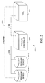
- FIG. 2 illustrates a pressure control system that controls pressure in a vacuum processing chamber by using a digital network to communicate pressure signals between a pair of pressure sensors and a pressure controller, in accordance with another embodiment of the present disclosure.
- a digital communication link is provided between a pressure sensor that makes measurements of pressure, and a pressure controller that controls the pressure to a desired set point in response to these pressure measurements.
- immunity may be acquired from ground noise that is often present in systems such as semiconductor processing tools, and that would adversely affect pressure control. Further, the effective dynamic range for the pressure measurement and control may be increased.
- FIG. 1 illustrates a pressure control system 100 that controls pressure in a tool 120, by using a digital communication network 150 to communicate pressure signals between a pressure sensor 130 and a pressure controller 140, in accordance with one embodiment of the present disclosure.
- the tool 120 may be a semiconductor processing tool, by way of example, but other types of processing tools are also within the scope of the present disclosure.
- the digital communication network 150 may be a bi-direction (or two-way) network that enables two-way communication of pressure-related signals and messages between the pressure sensor 130 and the pressure controller 140.
- the communication network 150 may be a one-way network, in which pressure-related communications may occur along one direction only, while transmissions along the other direction are reserved solely for housekeeping functions such as zeroing and error status.
- the pressure sensor 130 measures pressure within one or more vacuum chambers in the tool 120.
- the pressure sensor 130 may be a capacitance-based pressure transducer, in one embodiment of the present disclosure, although other types of pressure transducers are also within the scope of the present disclosure.
- the pressure sensor 130 may be a baratron manufactured by MKS Instruments, Inc.
- the pressure controller 140 receives from the pressure sensor 130, through the digital communication network 150, signals containing the pressure measurements by the pressure sensor 130.
- the pressure controller 140 also receives desired pressure set points from the tool 120, typically sent by a tool controller (not shown) within the tool 120.
- the pressure controller 140 controls pressure in the vacuum chamber(s) in the tool 120 so as to maintain the pressure at the desired pressure set points received from the tool 120.
- the pressure controller 140 includes a valve that opens and closes so as to control the flow rate of fluid into or out of the vacuum chamber and thereby controlling the pressure in the vacuum chamber.
- the digital communication network 150 enables closed loop sensor feedback for pressure control by the system 100.
- the digital communication network 150 may be a private network, such as CAN (Control Area Network) by way of example. Private digital networks generally allow for highly reliable packet transmission at regular, periodic intervals. It is desirable that the CAN network enable signal communication at an update rate of about 10 msec or higher.
- the digital communication network 150 be an isolated network that can communicate signals with substantially no interference from any other networks and any other processes going on in these networks. In this way, the digital communication network 150 would be able to deterministically transmit signals that are substantially noise-free.
- the digital communication network 150 may include one or more of the following: Ethernet TCP (Transmission Control Protocol)/IP (Internet Protocol); DeviceNet; CAN (Controller Area Network); UDP/IP (User Datagram Protocol / Internet Protocol); RS (Recommended Standard)-232; and RS (Recommended Standard)-485.
- Ethernet TCP Transmission Control Protocol
- IP Internet Protocol
- DeviceNet DeviceNet
- CAN Controller Area Network
- UDP/IP User Datagram Protocol / Internet Protocol
- RS Recommended Standard
- the pressure controller 140 may receive control signals (such as the pressure set point) from the tool 120 over a tool level communication link 180.
- This link 180 may be implemented using systems that may include, but are not limited to: Dnet; RS232; and Ethernet.
- Communications between the pressure sensor 130 and the tool 120 may also occur over a separate tool level communication link 170. While FIG. 1 illustrates this network 170 as an Ethernet, communication networks other than the Ethernet may be used implement the tool level communication link 170. Typically, signals relating to system diagnostic information may be communicated through the tool level link 170.
- These signals may contain information and/or commands that include, but are not limited to, the following: calibration and/or zeroing of the pressure sensor 130; dynamic range of the pressure sensor 130; and diagnostic information for the pressure control system 100. Diagnostic information may relate to factors that include, but are not limited to: heater temperature of the pressure sensor; shorting of a diaphragm in the pressure sensor 130; internal failure of the pressure sensor 130; cumulative drift of the pressure sensor 130; zeroing range of the pressure sensor; and the exceeding of the full scale range by the pressure sensor 130.
- the closed loop sensor feedback system described above may also be configured to support additional sensor input, in addition to supporting input from the pressure sensor 130.
- the pressure control system 100 may be configured to receive the output from an FRC (flow ratio controller) that provides a flow change feedforward signal to the pressure controller 140.
- FRC flow ratio controller
- Signals other than pressure measurement signals could also be communicated between the pressure sensor 130 and the pressure controller 140 through the digital communication network 170, in one embodiment of the present disclosure.
- FIG. 2 illustrates a pressure control system 200 that controls pressure in one or more vacuum processing chambers in a tool 220, in accordance with another embodiment of the present disclosure.
- the embodiment illustrated in FIG. 2 works in the same way, compared to the embodiment illustrated in FIG. 1 , except that in the system 200, a digital network 250 is used to communicate pressure signals between a pair of pressure sensors (illustrated as 230-1 and 230-2) and a pressure controller 240. While just two sensors have been illustrated in FIG. 2 , in general the number N of pressure sensors that can be connected to the digital network 250 may be variable, i.e. the user may have the flexibility of adding/removing desired numbers ofpressure sensors 230-1, 230-2, ..., 230-i from the digital network 250.
- the packet transmission for signals containing pressure measurement, diagnostics, and other information may occur in one or more ways, as described below.
- the pressure sensor(s) may send out a message to the pressure controller.
- An exemplary protocol may technically consist of a CAN Group 1 message ID 0, broadcast from the pressure sensors every 10ms.
- the message identifier may be an unsigned long, with the lowest six bits being the MacID of the sending pressure sensor (illustrated as 230-1 and 230-2). All other bits, which are unused, may be set to zero. This may produce a group I message that should take priority over any normal (group 2) Devicenet communications if present. This may also assure that the arbitration between the pressure sensor's messages will be handled by a lower level driver without additional work.
- a packet in the message may contain a message ID, a data length of 9, followed by the data itself.
- the reading in Torr may be represented as a four byte floating point number.
- the full scale in Torr may be represented as a four byte floating point number.
- the status may be represented as an eight bit unsigned integer.
- the status indicator bits may include, but are not limited to, the following:
- 0 & 1 bits may be required for zeroing.
- DeviceNet drivers at the pressure control valve may be modified to disable normal MacID filtering. Messages that don't have the valve's MacID may normally be dropped when received. In this example, messages with other MacIDs are readings from the baratrons. The MacIDs are used to determine which pressure sensor is the high range channel and which is the low. Messages with unused MacIDs are dropped. For example, defaults at the valve may be MacID 1 for low channel, and MacID 2 for high channel. These values can be changed in the valve and on the pressure sensors.
- the ADC calibration data may be used to convert Torr pressure/range readings into simulated ADC raw counts.
- the full scale range may be updated automatically if the valve's range for a transducer does not match the contents of a packet.
- the crossover point may also be adjusted appropriately.
- a message may be generated by a valve in the pressure controller 140, for example to initiate zeroing of one or more of the pressure sensors.
- the message identifier may be an unsigned long, with the lowest six bits being the commanded baratron's MacID. Bit 6 may be set to 1 but all other (unused) bits may be set to zero. This produces a group 1 message ID 1.
- the pressure sensor with the MacID that matches the message may do a zero.
- a default target value of 0% may be provided even if a traditional zero (0% assumed) is needed.
- the message packets may contain a message ID, a data length of 4, then the data itself.
- the zero target may be represented in percent of full scale as a four byte floating point number.
- commands to be added to the baratron's interface may include, but are not limited to:
- Commands to be added to the control valve's serial interface may include, but are not limited to:
- a digital communication link is provided between one or more pressure sensors and a pressure controller, so that noise-free and high dynamic range signals are provided between the pressure sensors and the pressure controller, at an update rate of 10 msec or higher.
- the digital communication link allows improved pressure control stability and dynamic range.
Landscapes
- Physics & Mathematics (AREA)
- Fluid Mechanics (AREA)
- Engineering & Computer Science (AREA)
- General Physics & Mathematics (AREA)
- Automation & Control Theory (AREA)
- Computer Networks & Wireless Communication (AREA)
- Signal Processing (AREA)
- Control Of Fluid Pressure (AREA)
- Measuring Fluid Pressure (AREA)
Description
- BACKGROUND
- Pressure controllers for processing tools, such as semiconductor processing tools, typically perform pressure control in one or more vacuum chambers in the tool so, in response to measurements of the actual pressure. Currently, analog communication links are used to communicate pressure signals between these pressure controllers and the pressure sensors that actually perform the pressure measurements. Also digital communication is used, see e.g.
WO 2006/119319 . - When analog communication links or known digital links are used to transmit pressure signals, filtering is required at the receiving end of the signal. This reduces the bandwidth of the system, which in turn can limit pressure control performance, in particular in vacuum systems with a fast time constant. Noise due to non-ideal grounding can also be a problem when analog signals are exchanged between the pressure sensor and the pressure controller in a pressure control system.
- There is a need for pressure control systems and methods that can avoid these adverse effects.
- SUMMARY
- A pressure control system for a tool includes a digital communication network between a pressure sensor and a pressure controller. The digital communication network is configured to communicate signals between the pressure sensor and the pressure controller. The pressure sensor is configured to measure pressure within a vacuum chamber in the tool. The pressure controller is responsive to pressure measurements, made by the pressure sensor and communicated to the pressure controller through the digital communication network, to control the pressure within the vacuum chamber so as to maintain the pressure in the vacuum chamber at a pressure set point received from the tool.
- A method of controlling pressure in a vacuum chamber in a tool may include: measuring pressure in the vacuum chamber, receiving from the tool a pressure set point for the vacuum chamber, and communicating the pressure measurement and the pressure set point to a pressure controller through a digital communication network. The method may further include controlling the pressure in the vacuum chamber in response to the received pressure measurement and pressure set point, so as to maintain pressure in the vacuum chamber at the pressure set point.
- BRIEF DESCRIPTION OF THE DRAWINGS
-
FIG. 1 illustrates a pressure control system that controls pressure in a vacuum processing chamber by using a digital network to communicate pressure signals between a pressure sensor and a pressure controller, in accordance with one embodiment of the present disclosure. -
FIG. 2 illustrates a pressure control system that controls pressure in a vacuum processing chamber by using a digital network to communicate pressure signals between a pair of pressure sensors and a pressure controller, in accordance with another embodiment of the present disclosure. - DETAILED DESCRIPTION
- Systems and methods for vacuum pressure control are disclosed in which a digital communication link is provided between a pressure sensor that makes measurements of pressure, and a pressure controller that controls the pressure to a desired set point in response to these pressure measurements. By using a digital communication link to communicate pressure signals between the pressure sensor and the pressure controller, immunity may be acquired from ground noise that is often present in systems such as semiconductor processing tools, and that would adversely affect pressure control. Further, the effective dynamic range for the pressure measurement and control may be increased.
-
FIG. 1 illustrates apressure control system 100 that controls pressure in atool 120, by using adigital communication network 150 to communicate pressure signals between apressure sensor 130 and apressure controller 140, in accordance with one embodiment of the present disclosure. Thetool 120 may be a semiconductor processing tool, by way of example, but other types of processing tools are also within the scope of the present disclosure. - The
digital communication network 150 may be a bi-direction (or two-way) network that enables two-way communication of pressure-related signals and messages between thepressure sensor 130 and thepressure controller 140. Alternatively, thecommunication network 150 may be a one-way network, in which pressure-related communications may occur along one direction only, while transmissions along the other direction are reserved solely for housekeeping functions such as zeroing and error status. - The
pressure sensor 130 measures pressure within one or more vacuum chambers in thetool 120. Thepressure sensor 130 may be a capacitance-based pressure transducer, in one embodiment of the present disclosure, although other types of pressure transducers are also within the scope of the present disclosure. For example, thepressure sensor 130 may be a baratron manufactured by MKS Instruments, Inc. - The
pressure controller 140 receives from thepressure sensor 130, through thedigital communication network 150, signals containing the pressure measurements by thepressure sensor 130. Thepressure controller 140 also receives desired pressure set points from thetool 120, typically sent by a tool controller (not shown) within thetool 120. In response to the received pressure measurement signals and pressure set points, thepressure controller 140 controls pressure in the vacuum chamber(s) in thetool 120 so as to maintain the pressure at the desired pressure set points received from thetool 120. Typically, thepressure controller 140 includes a valve that opens and closes so as to control the flow rate of fluid into or out of the vacuum chamber and thereby controlling the pressure in the vacuum chamber. - The
digital communication network 150 enables closed loop sensor feedback for pressure control by thesystem 100. Thedigital communication network 150 may be a private network, such as CAN (Control Area Network) by way of example. Private digital networks generally allow for highly reliable packet transmission at regular, periodic intervals. It is desirable that the CAN network enable signal communication at an update rate of about 10 msec or higher. - For purposes of the
pressure control system 100, it is desirable that thedigital communication network 150 be an isolated network that can communicate signals with substantially no interference from any other networks and any other processes going on in these networks. In this way, thedigital communication network 150 would be able to deterministically transmit signals that are substantially noise-free. - While an isolated and private
digital communication network 150 such as a CAN may be desirable, in some embodiments thedigital communication network 150 may include one or more of the following: Ethernet TCP (Transmission Control Protocol)/IP (Internet Protocol); DeviceNet; CAN (Controller Area Network); UDP/IP (User Datagram Protocol / Internet Protocol); RS (Recommended Standard)-232; and RS (Recommended Standard)-485. - The
pressure controller 140 may receive control signals (such as the pressure set point) from thetool 120 over a toollevel communication link 180. Thislink 180 may be implemented using systems that may include, but are not limited to: Dnet; RS232; and Ethernet. - Communications between the
pressure sensor 130 and thetool 120 may also occur over a separate toollevel communication link 170. WhileFIG. 1 illustrates thisnetwork 170 as an Ethernet, communication networks other than the Ethernet may be used implement the toollevel communication link 170. Typically, signals relating to system diagnostic information may be communicated through thetool level link 170. - These signals may contain information and/or commands that include, but are not limited to, the following: calibration and/or zeroing of the
pressure sensor 130; dynamic range of thepressure sensor 130; and diagnostic information for thepressure control system 100. Diagnostic information may relate to factors that include, but are not limited to: heater temperature of the pressure sensor; shorting of a diaphragm in thepressure sensor 130; internal failure of thepressure sensor 130; cumulative drift of thepressure sensor 130; zeroing range of the pressure sensor; and the exceeding of the full scale range by thepressure sensor 130. - The closed loop sensor feedback system described above may also be configured to support additional sensor input, in addition to supporting input from the
pressure sensor 130. For example, thepressure control system 100 may be configured to receive the output from an FRC (flow ratio controller) that provides a flow change feedforward signal to thepressure controller 140. - Signals other than pressure measurement signals, for example diagnostics information described above, could also be communicated between the
pressure sensor 130 and thepressure controller 140 through thedigital communication network 170, in one embodiment of the present disclosure. -
FIG. 2 illustrates apressure control system 200 that controls pressure in one or more vacuum processing chambers in atool 220, in accordance with another embodiment of the present disclosure. The embodiment illustrated inFIG. 2 works in the same way, compared to the embodiment illustrated inFIG. 1 , except that in thesystem 200, adigital network 250 is used to communicate pressure signals between a pair of pressure sensors (illustrated as 230-1 and 230-2) and apressure controller 240. While just two sensors have been illustrated inFIG. 2 , in general the number N of pressure sensors that can be connected to thedigital network 250 may be variable, i.e. the user may have the flexibility of adding/removing desired numbers ofpressure sensors 230-1, 230-2, ..., 230-i from thedigital network 250. - In an embodiment in which the digital communication network is a CAN network, the packet transmission for signals containing pressure measurement, diagnostics, and other information, may occur in one or more ways, as described below.
- In one example, the pressure sensor(s) may send out a message to the pressure controller. An exemplary protocol may technically consist of a CAN
Group 1 message ID 0, broadcast from the pressure sensors every 10ms. The message identifier may be an unsigned long, with the lowest six bits being the MacID of the sending pressure sensor (illustrated as 230-1 and 230-2). All other bits, which are unused, may be set to zero. This may produce a group I message that should take priority over any normal (group 2) Devicenet communications if present. This may also assure that the arbitration between the pressure sensor's messages will be handled by a lower level driver without additional work. - In this example, a packet in the message may contain a message ID, a data length of 9, followed by the data itself. The reading in Torr may be represented as a four byte floating point number. The full scale in Torr may be represented as a four byte floating point number. The status may be represented as an eight bit unsigned integer.
- The status indicator bits may include, but are not limited to, the following:
- 0) heater at control temperature;
- 1) pressure within zeroing range;
- 2) diaphragm shorted;
- 3) e-Baratron over 110% of full-scale range;
- 4) zero adjustment over 20% (further zeroing not allowed);
- 5) e-Baratron internal failure (for reasons such as heater circuit failure, and power supply out of spec);
- 6) cumulative drift out of range; and
- 7) unused at this time.
- 0 & 1 bits may be required for zeroing.
- DeviceNet drivers at the pressure control valve may be modified to disable normal MacID filtering. Messages that don't have the valve's MacID may normally be dropped when received. In this example, messages with other MacIDs are readings from the baratrons. The MacIDs are used to determine which pressure sensor is the high range channel and which is the low. Messages with unused MacIDs are dropped. For example, defaults at the valve may be
MacID 1 for low channel, and MacID 2 for high channel. These values can be changed in the valve and on the pressure sensors. - Data may be read on the pressure control valve and used instead of reading the ADC (analog-to-digital converter). The ADC calibration data may be used to convert Torr pressure/range readings into simulated ADC raw counts.
- The full scale range may be updated automatically if the valve's range for a transducer does not match the contents of a packet. The crossover point may also be adjusted appropriately.
- In another situation, a message may be generated by a valve in the
pressure controller 140, for example to initiate zeroing of one or more of the pressure sensors. The message identifier may be an unsigned long, with the lowest six bits being the commanded baratron's MacID. Bit 6 may be set to 1 but all other (unused) bits may be set to zero. This produces agroup 1message ID 1. The pressure sensor with the MacID that matches the message may do a zero. A default target value of 0% may be provided even if a traditional zero (0% assumed) is needed. - In this example, the message packets may contain a message ID, a data length of 4, then the data itself. The zero target may be represented in percent of full scale as a four byte floating point number.
- In the above example, commands to be added to the baratron's interface may include, but are not limited to:
- Enter digital baratron mode;
- Get/Set MacID of baratron;
- Commands to be added to the control valve's serial interface may include, but are not limited to:
- Enter digital baratron mode;
- Get/Set MacID of high or low channel pressure sensor;
- Report status of high or low channel pressure sensor; and
- Execute zero on high or low channel pressure sensor with or without a target.
- In sum, systems and methods have been described in which a digital communication link is provided between one or more pressure sensors and a pressure controller, so that noise-free and high dynamic range signals are provided between the pressure sensors and the pressure controller, at an update rate of 10 msec or higher. The digital communication link allows improved pressure control stability and dynamic range.
- While certain embodiments have been described of systems and methods for controlling pressure in the vacuum processing system, it is to be understood that the concepts implicit in these embodiments may be used in other embodiments as well. The protection of this application is limited solely to the claims that now follow.
Claims (16)
- A pressure control system, comprising: a pressure sensor (130) configured to measure pressure within a vacuum chamber in a processing tool (120) ; a pressure controller (140) configured to control the pressure within the vacuum chamber; characterized by;
a digital, private, communication network (150) between the pressure sensor (130) and the pressure controller (140) configured to provide closed loop sensor feedback including transmission of pressure measurement signals from the sensor (130) to the controller (140) substantially free of interference from any other networks,
a first tool level communication link (180), separate and isolated from the communication network (150), configured to provide set point signals from the tool (120) to the controller (140); and
a second tool level communication link (170), separate and isolated from the communication network (150) and separate from the first tool level communication link (180), configured to provide system diagnostic information between the tool and the sensor; wherein the pressure controller is responsive to pressure measurements made by the pressure sensor and communicated to the pressure controller through the digital communication network, to control the pressure within the vacuum chamber so as to maintain the pressure in the vacuum chamber at a pressure set point received from the processing tool. - The pressure control system of claim 1, wherein the private digital communication network (150) is configured to communicate the signals through packet transmission occurring at periodic time intervals.
- The pressure control system of claim 1, wherein the private digital communication network (150) is configured to deterministically transmit signals that are substantially free of noise.
- The pressure control system of claim 1, wherein the processing tool (120) comprises a semiconductor processing tool.
- The pressure control system of claim 1, wherein the second tool level communication link (170) is further configured to also communicate between the pressure sensor and the pressure controller signals relating to at least one of: calibration and zeroing of the pressure sensor; and dynamic range of the pressure sensor.
- The pressure control system of claim 1, wherein the diagnostic information relates to at least one of: heater temperature of the pressure sensor; shorting of a diaphragm in the pressure sensor; internal failure of the pressure sensor; cumulative drift of the pressure sensor; zeroing range of the pressure sensor; and exceeding of full scale range by the pressure sensor.
- The pressure control system of claim 1, wherein the private, digital communication network (150) is configured to communicate the signals at a signal update speed of about 10 msec or higher.
- The pressure control system of claim 1, wherein the private, digital communication network (150) comprises at least one of: Ethernet TCP (Transmission Control Protocol)/IP (Internet Protocol); DeviceNet; CAN (Controller Area Network); UDP/IP (User Datagram Protocol / Internet Protocol); RS (Recommended Standard)-232; and RS (Recommended Standard)-485,
- The pressure control system of claim 1, wherein the pressure sensor (130) comprises a capacitance-based pressure transducer.
- The pressure control system of claim 1, further comprising a mass flow meter coupled to the private, digital communication network (150), the mass flow controller configured to measure flow rate of fluid into and out of the vacuum chamber and to transmit to the pressure controller signals representing the measured flow rate.
- The pressure control system of claim 1, wherein the private, digital communication network (150) comprises at least one of: a one-way communication network configured to communicate pressure-related signals along a single direction; and
a bi-directional communication network configured to transmit pressure-related signals along two opposite directions. - The pressure control system of claim 1, further including a plurality N of pressure sensors coupled to the private digital communication network and the second tool level communication link (170), each of the plurality of pressure sensors configured to measure pressure within a vacuum chamber in a processing tool.
- The pressure control system of claim 12, wherein the number N of pressure sensors is variable.
- The pressure control system of claim 12, wherein the private digital communication network is configured to communicate the signals between the sensor and the controller through packet transmission occurring at periodic time intervals.
- A system comprising: a tool including a vacuum processing chamber, a pressure sensor (130) configured to measure the pressure within said vacuum chamber, a pressure controller (140) configured to control the pressure within said vacuum chamber, and a tool controller configured to generate tool control signals including at least one signal that provides a pressure set point for the vacuum processing chamber; characterized by;
a digital, private, communication network (150) between the pressure sensor (130) and the pressure controller (140) configured to provide closed loop sensor feedback including transmission of pressure measurement signals from the sensor (130) to the controller (140) substantially free of interference from any other networks,
a first tool level communication link (180), separate and isolated from the communication network (150), configured to provide set point signals from the tool (120) to the controller (140); and
a second tool level communication link (170), separate and isolated from the communication network (150) and separate from the first tool level communication link (180), configured to provide system diagnostic information between the tool and the sensor; wherein the pressure controller is responsive to pressure measurements made by the pressure sensor and communicated to the pressure controller through the digital communication network, to control the pressure within the vacuum chamber so as to maintain the pressure in the vacuum chamber at a pressure set point received from the processing tool. - A method of communicating among a vacuum chamber of a tool, a pressure sensor (130) and a pressure controller (140) so as to control pressure in the vacuum chamber in the tool, the method characterized by:measuring pressure in the vacuum chamber and transmitting a pressure measurement signal over a private digital communication network (150);receiving from the tool a signal representing a pressure set point for the vacuum chamber over a communication link separate and isolated from the private digital communication network;the pressure controller controlling the pressure in the vacuum chamber in response to the received pressure measurement and pressure set point, so as to maintain pressure in the vacuum chamber at the pressure set point; andproviding system diagnostic information over a second private communication link (170) separate from the private digital communication link between the sensor and the tool.
Applications Claiming Priority (2)
| Application Number | Priority Date | Filing Date | Title |
|---|---|---|---|
| US11/714,440 US20080216901A1 (en) | 2007-03-06 | 2007-03-06 | Pressure control for vacuum processing system |
| PCT/US2008/055610 WO2008109496A2 (en) | 2007-03-06 | 2008-03-03 | Pressure control for vacuum processing system |
Publications (2)
| Publication Number | Publication Date |
|---|---|
| EP2137586A2 EP2137586A2 (en) | 2009-12-30 |
| EP2137586B1 true EP2137586B1 (en) | 2013-05-08 |
Family
ID=39712155
Family Applications (1)
| Application Number | Title | Priority Date | Filing Date |
|---|---|---|---|
| EP20080731208 Not-in-force EP2137586B1 (en) | 2007-03-06 | 2008-03-03 | Pressure control for vacuum processing system |
Country Status (6)
| Country | Link |
|---|---|
| US (1) | US20080216901A1 (en) |
| EP (1) | EP2137586B1 (en) |
| JP (1) | JP5405323B2 (en) |
| KR (1) | KR20100014904A (en) |
| CN (1) | CN101681175B (en) |
| WO (1) | WO2008109496A2 (en) |
Families Citing this family (81)
| Publication number | Priority date | Publication date | Assignee | Title |
|---|---|---|---|---|
| US10283321B2 (en) | 2011-01-18 | 2019-05-07 | Applied Materials, Inc. | Semiconductor processing system and methods using capacitively coupled plasma |
| US9064815B2 (en) | 2011-03-14 | 2015-06-23 | Applied Materials, Inc. | Methods for etch of metal and metal-oxide films |
| US9267739B2 (en) | 2012-07-18 | 2016-02-23 | Applied Materials, Inc. | Pedestal with multi-zone temperature control and multiple purge capabilities |
| US9373517B2 (en) | 2012-08-02 | 2016-06-21 | Applied Materials, Inc. | Semiconductor processing with DC assisted RF power for improved control |
| US9132436B2 (en) | 2012-09-21 | 2015-09-15 | Applied Materials, Inc. | Chemical control features in wafer process equipment |
| US10256079B2 (en) | 2013-02-08 | 2019-04-09 | Applied Materials, Inc. | Semiconductor processing systems having multiple plasma configurations |
| US9309598B2 (en) | 2014-05-28 | 2016-04-12 | Applied Materials, Inc. | Oxide and metal removal |
| US9355922B2 (en) | 2014-10-14 | 2016-05-31 | Applied Materials, Inc. | Systems and methods for internal surface conditioning in plasma processing equipment |
| US9966240B2 (en) | 2014-10-14 | 2018-05-08 | Applied Materials, Inc. | Systems and methods for internal surface conditioning assessment in plasma processing equipment |
| US11637002B2 (en) | 2014-11-26 | 2023-04-25 | Applied Materials, Inc. | Methods and systems to enhance process uniformity |
| US10573496B2 (en) | 2014-12-09 | 2020-02-25 | Applied Materials, Inc. | Direct outlet toroidal plasma source |
| US10224210B2 (en) | 2014-12-09 | 2019-03-05 | Applied Materials, Inc. | Plasma processing system with direct outlet toroidal plasma source |
| US11257693B2 (en) | 2015-01-09 | 2022-02-22 | Applied Materials, Inc. | Methods and systems to improve pedestal temperature control |
| US20160225652A1 (en) | 2015-02-03 | 2016-08-04 | Applied Materials, Inc. | Low temperature chuck for plasma processing systems |
| US9728437B2 (en) | 2015-02-03 | 2017-08-08 | Applied Materials, Inc. | High temperature chuck for plasma processing systems |
| US9741593B2 (en) | 2015-08-06 | 2017-08-22 | Applied Materials, Inc. | Thermal management systems and methods for wafer processing systems |
| US9691645B2 (en) | 2015-08-06 | 2017-06-27 | Applied Materials, Inc. | Bolted wafer chuck thermal management systems and methods for wafer processing systems |
| US9349605B1 (en) | 2015-08-07 | 2016-05-24 | Applied Materials, Inc. | Oxide etch selectivity systems and methods |
| US10504700B2 (en) | 2015-08-27 | 2019-12-10 | Applied Materials, Inc. | Plasma etching systems and methods with secondary plasma injection |
| US10504754B2 (en) | 2016-05-19 | 2019-12-10 | Applied Materials, Inc. | Systems and methods for improved semiconductor etching and component protection |
| US10522371B2 (en) | 2016-05-19 | 2019-12-31 | Applied Materials, Inc. | Systems and methods for improved semiconductor etching and component protection |
| US9865484B1 (en) | 2016-06-29 | 2018-01-09 | Applied Materials, Inc. | Selective etch using material modification and RF pulsing |
| US10062575B2 (en) | 2016-09-09 | 2018-08-28 | Applied Materials, Inc. | Poly directional etch by oxidation |
| US10629473B2 (en) | 2016-09-09 | 2020-04-21 | Applied Materials, Inc. | Footing removal for nitride spacer |
| US10062585B2 (en) | 2016-10-04 | 2018-08-28 | Applied Materials, Inc. | Oxygen compatible plasma source |
| US10546729B2 (en) | 2016-10-04 | 2020-01-28 | Applied Materials, Inc. | Dual-channel showerhead with improved profile |
| US9934942B1 (en) | 2016-10-04 | 2018-04-03 | Applied Materials, Inc. | Chamber with flow-through source |
| US10062579B2 (en) | 2016-10-07 | 2018-08-28 | Applied Materials, Inc. | Selective SiN lateral recess |
| US9947549B1 (en) | 2016-10-10 | 2018-04-17 | Applied Materials, Inc. | Cobalt-containing material removal |
| US10163696B2 (en) | 2016-11-11 | 2018-12-25 | Applied Materials, Inc. | Selective cobalt removal for bottom up gapfill |
| US9768034B1 (en) | 2016-11-11 | 2017-09-19 | Applied Materials, Inc. | Removal methods for high aspect ratio structures |
| US10242908B2 (en) | 2016-11-14 | 2019-03-26 | Applied Materials, Inc. | Airgap formation with damage-free copper |
| US10026621B2 (en) | 2016-11-14 | 2018-07-17 | Applied Materials, Inc. | SiN spacer profile patterning |
| US10566206B2 (en) | 2016-12-27 | 2020-02-18 | Applied Materials, Inc. | Systems and methods for anisotropic material breakthrough |
| US10403507B2 (en) | 2017-02-03 | 2019-09-03 | Applied Materials, Inc. | Shaped etch profile with oxidation |
| US10431429B2 (en) | 2017-02-03 | 2019-10-01 | Applied Materials, Inc. | Systems and methods for radial and azimuthal control of plasma uniformity |
| US10043684B1 (en) | 2017-02-06 | 2018-08-07 | Applied Materials, Inc. | Self-limiting atomic thermal etching systems and methods |
| US10319739B2 (en) | 2017-02-08 | 2019-06-11 | Applied Materials, Inc. | Accommodating imperfectly aligned memory holes |
| US10943834B2 (en) | 2017-03-13 | 2021-03-09 | Applied Materials, Inc. | Replacement contact process |
| US10319649B2 (en) | 2017-04-11 | 2019-06-11 | Applied Materials, Inc. | Optical emission spectroscopy (OES) for remote plasma monitoring |
| JP7176860B6 (en) | 2017-05-17 | 2022-12-16 | アプライド マテリアルズ インコーポレイテッド | Semiconductor processing chamber to improve precursor flow |
| US11276590B2 (en) | 2017-05-17 | 2022-03-15 | Applied Materials, Inc. | Multi-zone semiconductor substrate supports |
| US11276559B2 (en) | 2017-05-17 | 2022-03-15 | Applied Materials, Inc. | Semiconductor processing chamber for multiple precursor flow |
| US10497579B2 (en) | 2017-05-31 | 2019-12-03 | Applied Materials, Inc. | Water-free etching methods |
| US10049891B1 (en) | 2017-05-31 | 2018-08-14 | Applied Materials, Inc. | Selective in situ cobalt residue removal |
| US10920320B2 (en) | 2017-06-16 | 2021-02-16 | Applied Materials, Inc. | Plasma health determination in semiconductor substrate processing reactors |
| US10541246B2 (en) | 2017-06-26 | 2020-01-21 | Applied Materials, Inc. | 3D flash memory cells which discourage cross-cell electrical tunneling |
| US10727080B2 (en) | 2017-07-07 | 2020-07-28 | Applied Materials, Inc. | Tantalum-containing material removal |
| US10541184B2 (en) | 2017-07-11 | 2020-01-21 | Applied Materials, Inc. | Optical emission spectroscopic techniques for monitoring etching |
| US10354889B2 (en) | 2017-07-17 | 2019-07-16 | Applied Materials, Inc. | Non-halogen etching of silicon-containing materials |
| US10170336B1 (en) | 2017-08-04 | 2019-01-01 | Applied Materials, Inc. | Methods for anisotropic control of selective silicon removal |
| US10043674B1 (en) | 2017-08-04 | 2018-08-07 | Applied Materials, Inc. | Germanium etching systems and methods |
| US10297458B2 (en) | 2017-08-07 | 2019-05-21 | Applied Materials, Inc. | Process window widening using coated parts in plasma etch processes |
| US10283324B1 (en) | 2017-10-24 | 2019-05-07 | Applied Materials, Inc. | Oxygen treatment for nitride etching |
| US10128086B1 (en) | 2017-10-24 | 2018-11-13 | Applied Materials, Inc. | Silicon pretreatment for nitride removal |
| US10256112B1 (en) | 2017-12-08 | 2019-04-09 | Applied Materials, Inc. | Selective tungsten removal |
| US10903054B2 (en) | 2017-12-19 | 2021-01-26 | Applied Materials, Inc. | Multi-zone gas distribution systems and methods |
| US11328909B2 (en) | 2017-12-22 | 2022-05-10 | Applied Materials, Inc. | Chamber conditioning and removal processes |
| US10854426B2 (en) | 2018-01-08 | 2020-12-01 | Applied Materials, Inc. | Metal recess for semiconductor structures |
| US10679870B2 (en) | 2018-02-15 | 2020-06-09 | Applied Materials, Inc. | Semiconductor processing chamber multistage mixing apparatus |
| US10964512B2 (en) | 2018-02-15 | 2021-03-30 | Applied Materials, Inc. | Semiconductor processing chamber multistage mixing apparatus and methods |
| TWI716818B (en) | 2018-02-28 | 2021-01-21 | 美商應用材料股份有限公司 | Systems and methods to form airgaps |
| US10593560B2 (en) | 2018-03-01 | 2020-03-17 | Applied Materials, Inc. | Magnetic induction plasma source for semiconductor processes and equipment |
| US10319600B1 (en) | 2018-03-12 | 2019-06-11 | Applied Materials, Inc. | Thermal silicon etch |
| US10497573B2 (en) | 2018-03-13 | 2019-12-03 | Applied Materials, Inc. | Selective atomic layer etching of semiconductor materials |
| US10573527B2 (en) | 2018-04-06 | 2020-02-25 | Applied Materials, Inc. | Gas-phase selective etching systems and methods |
| US10490406B2 (en) | 2018-04-10 | 2019-11-26 | Appled Materials, Inc. | Systems and methods for material breakthrough |
| US10699879B2 (en) | 2018-04-17 | 2020-06-30 | Applied Materials, Inc. | Two piece electrode assembly with gap for plasma control |
| US10886137B2 (en) | 2018-04-30 | 2021-01-05 | Applied Materials, Inc. | Selective nitride removal |
| US10872778B2 (en) | 2018-07-06 | 2020-12-22 | Applied Materials, Inc. | Systems and methods utilizing solid-phase etchants |
| US10755941B2 (en) | 2018-07-06 | 2020-08-25 | Applied Materials, Inc. | Self-limiting selective etching systems and methods |
| US10672642B2 (en) | 2018-07-24 | 2020-06-02 | Applied Materials, Inc. | Systems and methods for pedestal configuration |
| US10892198B2 (en) | 2018-09-14 | 2021-01-12 | Applied Materials, Inc. | Systems and methods for improved performance in semiconductor processing |
| US11049755B2 (en) | 2018-09-14 | 2021-06-29 | Applied Materials, Inc. | Semiconductor substrate supports with embedded RF shield |
| US11062887B2 (en) | 2018-09-17 | 2021-07-13 | Applied Materials, Inc. | High temperature RF heater pedestals |
| US11417534B2 (en) | 2018-09-21 | 2022-08-16 | Applied Materials, Inc. | Selective material removal |
| US11682560B2 (en) | 2018-10-11 | 2023-06-20 | Applied Materials, Inc. | Systems and methods for hafnium-containing film removal |
| US11121002B2 (en) | 2018-10-24 | 2021-09-14 | Applied Materials, Inc. | Systems and methods for etching metals and metal derivatives |
| US11437242B2 (en) | 2018-11-27 | 2022-09-06 | Applied Materials, Inc. | Selective removal of silicon-containing materials |
| US11721527B2 (en) | 2019-01-07 | 2023-08-08 | Applied Materials, Inc. | Processing chamber mixing systems |
| US10920319B2 (en) | 2019-01-11 | 2021-02-16 | Applied Materials, Inc. | Ceramic showerheads with conductive electrodes |
Family Cites Families (17)
| Publication number | Priority date | Publication date | Assignee | Title |
|---|---|---|---|---|
| US6142163A (en) * | 1996-03-29 | 2000-11-07 | Lam Research Corporation | Method and apparatus for pressure control in vacuum processors |
| JP3470218B2 (en) * | 1997-08-12 | 2003-11-25 | 東京エレクトロン株式会社 | Gas system control method and apparatus |
| US6035878A (en) * | 1997-09-22 | 2000-03-14 | Fisher Controls International, Inc. | Diagnostic device and method for pressure regulator |
| JPH11230793A (en) * | 1998-02-12 | 1999-08-27 | Tokyo Gas Co Ltd | Flow monitoring device |
| JPH11312640A (en) * | 1998-02-25 | 1999-11-09 | Canon Inc | Processing apparatus and device manufacturing method using the processing apparatus |
| JP3577236B2 (en) * | 1999-03-11 | 2004-10-13 | シーケーディ株式会社 | Gas supply control device |
| US6814096B2 (en) * | 2000-12-15 | 2004-11-09 | Nor-Cal Products, Inc. | Pressure controller and method |
| MY134338A (en) * | 2001-08-24 | 2007-12-31 | Asml Us Inc | Atmospheric pressure wafer processing reactor having an internal pressure control system and method |
| US6948508B2 (en) * | 2002-06-24 | 2005-09-27 | Mks Instruments, Inc. | Apparatus and method for self-calibration of mass flow controller |
| JP4195837B2 (en) * | 2003-06-20 | 2008-12-17 | 東京エレクトロン株式会社 | Gas diversion supply apparatus and gas diversion supply method |
| US6986359B2 (en) * | 2004-03-09 | 2006-01-17 | Mks Instruments, Inc. | System and method for controlling pressure in remote zones |
| US7464721B2 (en) * | 2004-06-14 | 2008-12-16 | Rosemount Inc. | Process equipment validation |
| US7673645B2 (en) * | 2005-04-21 | 2010-03-09 | Mks Instruments, Inc. | Gas delivery method and system including a flow ratio controller using a multiple antisymmetric optimal control arrangement |
| US7890220B2 (en) * | 2005-05-03 | 2011-02-15 | Mks Instruments, Inc. | Low overhead closed loop control system |
| US8190238B2 (en) * | 2005-12-09 | 2012-05-29 | Hansen Medical, Inc. | Robotic catheter system and methods |
| JP6034546B2 (en) * | 2006-03-16 | 2016-11-30 | アプライド マテリアルズ インコーポレイテッドApplied Materials,Incorporated | Method and apparatus for improved operation of mitigation system |
| US7643909B2 (en) * | 2006-03-30 | 2010-01-05 | Mks Instruments, Inc. | Highly responsive master-slave valve positioning |
-
2007
- 2007-03-06 US US11/714,440 patent/US20080216901A1/en not_active Abandoned
-
2008
- 2008-03-03 CN CN200880007490.0A patent/CN101681175B/en not_active Expired - Fee Related
- 2008-03-03 KR KR20097018456A patent/KR20100014904A/en not_active Ceased
- 2008-03-03 EP EP20080731208 patent/EP2137586B1/en not_active Not-in-force
- 2008-03-03 JP JP2009552816A patent/JP5405323B2/en active Active
- 2008-03-03 WO PCT/US2008/055610 patent/WO2008109496A2/en not_active Ceased
Also Published As
| Publication number | Publication date |
|---|---|
| CN101681175A (en) | 2010-03-24 |
| JP5405323B2 (en) | 2014-02-05 |
| US20080216901A1 (en) | 2008-09-11 |
| CN101681175B (en) | 2014-08-27 |
| WO2008109496A3 (en) | 2009-10-29 |
| WO2008109496A2 (en) | 2008-09-12 |
| KR20100014904A (en) | 2010-02-11 |
| JP2010520563A (en) | 2010-06-10 |
| EP2137586A2 (en) | 2009-12-30 |
Similar Documents
| Publication | Publication Date | Title |
|---|---|---|
| US20080216901A1 (en) | Pressure control for vacuum processing system | |
| EP2002232B1 (en) | Pressure transmitter assembly | |
| JP2009532953A (en) | Apparatus, system, and method for integrating wireless device into distributed control system | |
| WO2002059702A3 (en) | Variable power control for process control instruments | |
| US20080167748A1 (en) | Integrated pressure and flow ratio control system | |
| WO2002047324A3 (en) | Network device interface for digitally interfacing data channels to a controller via a network | |
| CN102545960B (en) | Communication device capable of quickly adjusting parameters of analog echo cancellation circuit and related method | |
| CA3033336C (en) | Slip monitor and control | |
| TW200610330A (en) | System and method for automatically calibrating two-tap and multi-tap equalization for a communications link | |
| EP0961402A3 (en) | A transmitter | |
| MX2012002540A (en) | Valve calibration. | |
| KR102294823B1 (en) | Relay | |
| EP1785837A3 (en) | Storage device system and signal transmission method for storage device system | |
| WO2007146594A2 (en) | Method and system of field device protocol masking | |
| CA1274102A (en) | Self-zeroing pressure transmitter with automatic pressure manifold | |
| EP3494378A1 (en) | Process transmitter isolation unit compensation | |
| EP1255389B1 (en) | Apparatus and method for adaptive control | |
| US7643909B2 (en) | Highly responsive master-slave valve positioning | |
| US20240101408A1 (en) | Method for Calibrating a Filling System and Filling System | |
| WO2001005013A3 (en) | Detecting and mapping power line loss | |
| CN208766653U (en) | Analog front-end device applied to two-wire system bus | |
| AU2008360008B2 (en) | Method and apparatus for pulse width modulation signal processing | |
| US20050060108A1 (en) | Field-measuring system and method supported by PDA | |
| KR20110042589A (en) | Remote terminal device with wireless sensor network function | |
| CN110016657A (en) | Flow control methods and device, reaction chamber |
Legal Events
| Date | Code | Title | Description |
|---|---|---|---|
| PUAI | Public reference made under article 153(3) epc to a published international application that has entered the european phase |
Free format text: ORIGINAL CODE: 0009012 |
|
| 17P | Request for examination filed |
Effective date: 20091006 |
|
| AK | Designated contracting states |
Kind code of ref document: A2 Designated state(s): AT BE BG CH CY CZ DE DK EE ES FI FR GB GR HR HU IE IS IT LI LT LU LV MC MT NL NO PL PT RO SE SI SK TR |
|
| 17Q | First examination report despatched |
Effective date: 20100825 |
|
| DAX | Request for extension of the european patent (deleted) | ||
| GRAP | Despatch of communication of intention to grant a patent |
Free format text: ORIGINAL CODE: EPIDOSNIGR1 |
|
| GRAS | Grant fee paid |
Free format text: ORIGINAL CODE: EPIDOSNIGR3 |
|
| GRAA | (expected) grant |
Free format text: ORIGINAL CODE: 0009210 |
|
| AK | Designated contracting states |
Kind code of ref document: B1 Designated state(s): AT BE BG CH CY CZ DE DK EE ES FI FR GB GR HR HU IE IS IT LI LT LU LV MC MT NL NO PL PT RO SE SI SK TR |
|
| REG | Reference to a national code |
Ref country code: GB Ref legal event code: FG4D |
|
| REG | Reference to a national code |
Ref country code: CH Ref legal event code: EP Ref country code: AT Ref legal event code: REF Ref document number: 611363 Country of ref document: AT Kind code of ref document: T Effective date: 20130515 |
|
| REG | Reference to a national code |
Ref country code: IE Ref legal event code: FG4D |
|
| REG | Reference to a national code |
Ref country code: DE Ref legal event code: R096 Ref document number: 602008024424 Country of ref document: DE Effective date: 20130704 |
|
| REG | Reference to a national code |
Ref country code: AT Ref legal event code: MK05 Ref document number: 611363 Country of ref document: AT Kind code of ref document: T Effective date: 20130508 |
|
| REG | Reference to a national code |
Ref country code: LT Ref legal event code: MG4D |
|
| REG | Reference to a national code |
Ref country code: NL Ref legal event code: VDEP Effective date: 20130508 |
|
| PG25 | Lapsed in a contracting state [announced via postgrant information from national office to epo] |
Ref country code: SI Free format text: LAPSE BECAUSE OF FAILURE TO SUBMIT A TRANSLATION OF THE DESCRIPTION OR TO PAY THE FEE WITHIN THE PRESCRIBED TIME-LIMIT Effective date: 20130508 Ref country code: ES Free format text: LAPSE BECAUSE OF FAILURE TO SUBMIT A TRANSLATION OF THE DESCRIPTION OR TO PAY THE FEE WITHIN THE PRESCRIBED TIME-LIMIT Effective date: 20130819 Ref country code: FI Free format text: LAPSE BECAUSE OF FAILURE TO SUBMIT A TRANSLATION OF THE DESCRIPTION OR TO PAY THE FEE WITHIN THE PRESCRIBED TIME-LIMIT Effective date: 20130508 Ref country code: PT Free format text: LAPSE BECAUSE OF FAILURE TO SUBMIT A TRANSLATION OF THE DESCRIPTION OR TO PAY THE FEE WITHIN THE PRESCRIBED TIME-LIMIT Effective date: 20130909 Ref country code: GR Free format text: LAPSE BECAUSE OF FAILURE TO SUBMIT A TRANSLATION OF THE DESCRIPTION OR TO PAY THE FEE WITHIN THE PRESCRIBED TIME-LIMIT Effective date: 20130809 Ref country code: LT Free format text: LAPSE BECAUSE OF FAILURE TO SUBMIT A TRANSLATION OF THE DESCRIPTION OR TO PAY THE FEE WITHIN THE PRESCRIBED TIME-LIMIT Effective date: 20130508 Ref country code: SE Free format text: LAPSE BECAUSE OF FAILURE TO SUBMIT A TRANSLATION OF THE DESCRIPTION OR TO PAY THE FEE WITHIN THE PRESCRIBED TIME-LIMIT Effective date: 20130508 Ref country code: AT Free format text: LAPSE BECAUSE OF FAILURE TO SUBMIT A TRANSLATION OF THE DESCRIPTION OR TO PAY THE FEE WITHIN THE PRESCRIBED TIME-LIMIT Effective date: 20130508 Ref country code: NO Free format text: LAPSE BECAUSE OF FAILURE TO SUBMIT A TRANSLATION OF THE DESCRIPTION OR TO PAY THE FEE WITHIN THE PRESCRIBED TIME-LIMIT Effective date: 20130808 Ref country code: IS Free format text: LAPSE BECAUSE OF FAILURE TO SUBMIT A TRANSLATION OF THE DESCRIPTION OR TO PAY THE FEE WITHIN THE PRESCRIBED TIME-LIMIT Effective date: 20130908 |
|
| PG25 | Lapsed in a contracting state [announced via postgrant information from national office to epo] |
Ref country code: HR Free format text: LAPSE BECAUSE OF FAILURE TO SUBMIT A TRANSLATION OF THE DESCRIPTION OR TO PAY THE FEE WITHIN THE PRESCRIBED TIME-LIMIT Effective date: 20130508 Ref country code: PL Free format text: LAPSE BECAUSE OF FAILURE TO SUBMIT A TRANSLATION OF THE DESCRIPTION OR TO PAY THE FEE WITHIN THE PRESCRIBED TIME-LIMIT Effective date: 20130508 Ref country code: BG Free format text: LAPSE BECAUSE OF FAILURE TO SUBMIT A TRANSLATION OF THE DESCRIPTION OR TO PAY THE FEE WITHIN THE PRESCRIBED TIME-LIMIT Effective date: 20130808 Ref country code: CY Free format text: LAPSE BECAUSE OF FAILURE TO SUBMIT A TRANSLATION OF THE DESCRIPTION OR TO PAY THE FEE WITHIN THE PRESCRIBED TIME-LIMIT Effective date: 20130508 |
|
| PG25 | Lapsed in a contracting state [announced via postgrant information from national office to epo] |
Ref country code: LV Free format text: LAPSE BECAUSE OF FAILURE TO SUBMIT A TRANSLATION OF THE DESCRIPTION OR TO PAY THE FEE WITHIN THE PRESCRIBED TIME-LIMIT Effective date: 20130508 |
|
| PG25 | Lapsed in a contracting state [announced via postgrant information from national office to epo] |
Ref country code: DK Free format text: LAPSE BECAUSE OF FAILURE TO SUBMIT A TRANSLATION OF THE DESCRIPTION OR TO PAY THE FEE WITHIN THE PRESCRIBED TIME-LIMIT Effective date: 20130508 Ref country code: BE Free format text: LAPSE BECAUSE OF FAILURE TO SUBMIT A TRANSLATION OF THE DESCRIPTION OR TO PAY THE FEE WITHIN THE PRESCRIBED TIME-LIMIT Effective date: 20130508 Ref country code: CZ Free format text: LAPSE BECAUSE OF FAILURE TO SUBMIT A TRANSLATION OF THE DESCRIPTION OR TO PAY THE FEE WITHIN THE PRESCRIBED TIME-LIMIT Effective date: 20130508 Ref country code: EE Free format text: LAPSE BECAUSE OF FAILURE TO SUBMIT A TRANSLATION OF THE DESCRIPTION OR TO PAY THE FEE WITHIN THE PRESCRIBED TIME-LIMIT Effective date: 20130508 Ref country code: SK Free format text: LAPSE BECAUSE OF FAILURE TO SUBMIT A TRANSLATION OF THE DESCRIPTION OR TO PAY THE FEE WITHIN THE PRESCRIBED TIME-LIMIT Effective date: 20130508 |
|
| PG25 | Lapsed in a contracting state [announced via postgrant information from national office to epo] |
Ref country code: RO Free format text: LAPSE BECAUSE OF FAILURE TO SUBMIT A TRANSLATION OF THE DESCRIPTION OR TO PAY THE FEE WITHIN THE PRESCRIBED TIME-LIMIT Effective date: 20130508 Ref country code: NL Free format text: LAPSE BECAUSE OF FAILURE TO SUBMIT A TRANSLATION OF THE DESCRIPTION OR TO PAY THE FEE WITHIN THE PRESCRIBED TIME-LIMIT Effective date: 20130508 Ref country code: IT Free format text: LAPSE BECAUSE OF FAILURE TO SUBMIT A TRANSLATION OF THE DESCRIPTION OR TO PAY THE FEE WITHIN THE PRESCRIBED TIME-LIMIT Effective date: 20130508 |
|
| PLBE | No opposition filed within time limit |
Free format text: ORIGINAL CODE: 0009261 |
|
| STAA | Information on the status of an ep patent application or granted ep patent |
Free format text: STATUS: NO OPPOSITION FILED WITHIN TIME LIMIT |
|
| 26N | No opposition filed |
Effective date: 20140211 |
|
| REG | Reference to a national code |
Ref country code: DE Ref legal event code: R097 Ref document number: 602008024424 Country of ref document: DE Effective date: 20140211 |
|
| PG25 | Lapsed in a contracting state [announced via postgrant information from national office to epo] |
Ref country code: LU Free format text: LAPSE BECAUSE OF FAILURE TO SUBMIT A TRANSLATION OF THE DESCRIPTION OR TO PAY THE FEE WITHIN THE PRESCRIBED TIME-LIMIT Effective date: 20140303 |
|
| REG | Reference to a national code |
Ref country code: CH Ref legal event code: PL |
|
| REG | Reference to a national code |
Ref country code: FR Ref legal event code: ST Effective date: 20141128 |
|
| REG | Reference to a national code |
Ref country code: IE Ref legal event code: MM4A |
|
| PG25 | Lapsed in a contracting state [announced via postgrant information from national office to epo] |
Ref country code: LI Free format text: LAPSE BECAUSE OF NON-PAYMENT OF DUE FEES Effective date: 20140331 Ref country code: CH Free format text: LAPSE BECAUSE OF NON-PAYMENT OF DUE FEES Effective date: 20140331 Ref country code: FR Free format text: LAPSE BECAUSE OF NON-PAYMENT OF DUE FEES Effective date: 20140331 Ref country code: IE Free format text: LAPSE BECAUSE OF NON-PAYMENT OF DUE FEES Effective date: 20140303 |
|
| PG25 | Lapsed in a contracting state [announced via postgrant information from national office to epo] |
Ref country code: MT Free format text: LAPSE BECAUSE OF FAILURE TO SUBMIT A TRANSLATION OF THE DESCRIPTION OR TO PAY THE FEE WITHIN THE PRESCRIBED TIME-LIMIT Effective date: 20130508 |
|
| PG25 | Lapsed in a contracting state [announced via postgrant information from national office to epo] |
Ref country code: MC Free format text: LAPSE BECAUSE OF FAILURE TO SUBMIT A TRANSLATION OF THE DESCRIPTION OR TO PAY THE FEE WITHIN THE PRESCRIBED TIME-LIMIT Effective date: 20130508 |
|
| PG25 | Lapsed in a contracting state [announced via postgrant information from national office to epo] |
Ref country code: TR Free format text: LAPSE BECAUSE OF FAILURE TO SUBMIT A TRANSLATION OF THE DESCRIPTION OR TO PAY THE FEE WITHIN THE PRESCRIBED TIME-LIMIT Effective date: 20130508 Ref country code: HU Free format text: LAPSE BECAUSE OF FAILURE TO SUBMIT A TRANSLATION OF THE DESCRIPTION OR TO PAY THE FEE WITHIN THE PRESCRIBED TIME-LIMIT; INVALID AB INITIO Effective date: 20080303 |
|
| PGFP | Annual fee paid to national office [announced via postgrant information from national office to epo] |
Ref country code: GB Payment date: 20230327 Year of fee payment: 16 Ref country code: DE Payment date: 20230329 Year of fee payment: 16 |
|
| REG | Reference to a national code |
Ref country code: DE Ref legal event code: R119 Ref document number: 602008024424 Country of ref document: DE |
|
| GBPC | Gb: european patent ceased through non-payment of renewal fee |
Effective date: 20240303 |
|
| PG25 | Lapsed in a contracting state [announced via postgrant information from national office to epo] |
Ref country code: DE Free format text: LAPSE BECAUSE OF NON-PAYMENT OF DUE FEES Effective date: 20241001 |
|
| PG25 | Lapsed in a contracting state [announced via postgrant information from national office to epo] |
Ref country code: GB Free format text: LAPSE BECAUSE OF NON-PAYMENT OF DUE FEES Effective date: 20240303 |
|
| PG25 | Lapsed in a contracting state [announced via postgrant information from national office to epo] |
Ref country code: GB Free format text: LAPSE BECAUSE OF NON-PAYMENT OF DUE FEES Effective date: 20240303 Ref country code: DE Free format text: LAPSE BECAUSE OF NON-PAYMENT OF DUE FEES Effective date: 20241001 |