EP2137012B1 - System, method and computer program of estimating tire pressure deviations - Google Patents
System, method and computer program of estimating tire pressure deviations Download PDFInfo
- Publication number
- EP2137012B1 EP2137012B1 EP07723346.8A EP07723346A EP2137012B1 EP 2137012 B1 EP2137012 B1 EP 2137012B1 EP 07723346 A EP07723346 A EP 07723346A EP 2137012 B1 EP2137012 B1 EP 2137012B1
- Authority
- EP
- European Patent Office
- Prior art keywords
- pressure
- tire
- detector
- detectors
- detecting
- Prior art date
- Legal status (The legal status is an assumption and is not a legal conclusion. Google has not performed a legal analysis and makes no representation as to the accuracy of the status listed.)
- Not-in-force
Links
- 238000000034 method Methods 0.000 title claims description 16
- 238000004590 computer program Methods 0.000 title claims description 7
- 238000012544 monitoring process Methods 0.000 claims description 26
- 238000009792 diffusion process Methods 0.000 claims description 17
- 230000004044 response Effects 0.000 claims description 5
- 238000010183 spectrum analysis Methods 0.000 claims description 4
- 230000003213 activating effect Effects 0.000 claims 3
- 230000006870 function Effects 0.000 description 16
- 238000001228 spectrum Methods 0.000 description 7
- 238000004458 analytical method Methods 0.000 description 6
- 238000001514 detection method Methods 0.000 description 6
- 230000006978 adaptation Effects 0.000 description 5
- 238000010586 diagram Methods 0.000 description 4
- 230000001133 acceleration Effects 0.000 description 3
- 238000013459 approach Methods 0.000 description 3
- 230000003247 decreasing effect Effects 0.000 description 3
- 230000001419 dependent effect Effects 0.000 description 3
- 238000011156 evaluation Methods 0.000 description 3
- 238000012986 modification Methods 0.000 description 3
- 230000004048 modification Effects 0.000 description 3
- 238000007781 pre-processing Methods 0.000 description 3
- 230000000295 complement effect Effects 0.000 description 2
- 230000000694 effects Effects 0.000 description 2
- 239000000446 fuel Substances 0.000 description 2
- 238000010606 normalization Methods 0.000 description 2
- 230000003595 spectral effect Effects 0.000 description 2
- 238000005299 abrasion Methods 0.000 description 1
- 230000004913 activation Effects 0.000 description 1
- 230000003044 adaptive effect Effects 0.000 description 1
- 239000000654 additive Substances 0.000 description 1
- 230000000996 additive effect Effects 0.000 description 1
- 230000003321 amplification Effects 0.000 description 1
- 230000033228 biological regulation Effects 0.000 description 1
- 230000008859 change Effects 0.000 description 1
- 238000010219 correlation analysis Methods 0.000 description 1
- 238000007405 data analysis Methods 0.000 description 1
- 230000009849 deactivation Effects 0.000 description 1
- 238000009795 derivation Methods 0.000 description 1
- 238000013461 design Methods 0.000 description 1
- 238000003745 diagnosis Methods 0.000 description 1
- 230000020169 heat generation Effects 0.000 description 1
- 230000006872 improvement Effects 0.000 description 1
- 230000000977 initiatory effect Effects 0.000 description 1
- 230000007257 malfunction Effects 0.000 description 1
- 238000013178 mathematical model Methods 0.000 description 1
- 230000007246 mechanism Effects 0.000 description 1
- 238000003199 nucleic acid amplification method Methods 0.000 description 1
- 238000011045 prefiltration Methods 0.000 description 1
- 230000008569 process Effects 0.000 description 1
- 230000002123 temporal effect Effects 0.000 description 1
Images





Classifications
-
- B—PERFORMING OPERATIONS; TRANSPORTING
- B60—VEHICLES IN GENERAL
- B60C—VEHICLE TYRES; TYRE INFLATION; TYRE CHANGING; CONNECTING VALVES TO INFLATABLE ELASTIC BODIES IN GENERAL; DEVICES OR ARRANGEMENTS RELATED TO TYRES
- B60C23/00—Devices for measuring, signalling, controlling, or distributing tyre pressure or temperature, specially adapted for mounting on vehicles; Arrangement of tyre inflating devices on vehicles, e.g. of pumps or of tanks; Tyre cooling arrangements
- B60C23/06—Signalling devices actuated by deformation of the tyre, e.g. tyre mounted deformation sensors or indirect determination of tyre deformation based on wheel speed, wheel-centre to ground distance or inclination of wheel axle
- B60C23/061—Signalling devices actuated by deformation of the tyre, e.g. tyre mounted deformation sensors or indirect determination of tyre deformation based on wheel speed, wheel-centre to ground distance or inclination of wheel axle by monitoring wheel speed
-
- B—PERFORMING OPERATIONS; TRANSPORTING
- B60—VEHICLES IN GENERAL
- B60C—VEHICLE TYRES; TYRE INFLATION; TYRE CHANGING; CONNECTING VALVES TO INFLATABLE ELASTIC BODIES IN GENERAL; DEVICES OR ARRANGEMENTS RELATED TO TYRES
- B60C23/00—Devices for measuring, signalling, controlling, or distributing tyre pressure or temperature, specially adapted for mounting on vehicles; Arrangement of tyre inflating devices on vehicles, e.g. of pumps or of tanks; Tyre cooling arrangements
- B60C23/06—Signalling devices actuated by deformation of the tyre, e.g. tyre mounted deformation sensors or indirect determination of tyre deformation based on wheel speed, wheel-centre to ground distance or inclination of wheel axle
- B60C23/061—Signalling devices actuated by deformation of the tyre, e.g. tyre mounted deformation sensors or indirect determination of tyre deformation based on wheel speed, wheel-centre to ground distance or inclination of wheel axle by monitoring wheel speed
- B60C23/062—Frequency spectrum analysis of wheel speed signals, e.g. using Fourier transformation
Definitions
- the invention relates in general to monitoring the tire pressure of a number of tires in a vehicle, and in particular to a system, method and computer program for estimating tire pressure deviations in a plurality of tires in a vehicle.
- tire pressure monitoring systems are increasingly integrated in the vehicle electronic in order to warn the vehicle driver of any significant deviation from normal tire pressure.
- Tire pressure monitoring systems in general work either directly (i.e. with a tire pressure sensor) or indirectly (i.e. having no tire pressure sensor).
- Direct monitoring systems are usually very precise, but expensive due to the required additional measuring equipment. Indirect systems are cheaper, but it is naturally more difficult to obtain reliable and useful results.
- Indirect tire pressure monitoring systems mostly use for their estimations signals from existing sensors measuring, for instance, the angular velocity of the wheels, which are used by antilock braking systems (ABS). Based on the angular velocity signals the systems may in particular calculate changes in the wheel radii or observe the spectrum of the angular velocity signals. From this, the system may deduce information about tire pressure derivations.
- a conventional indirect tire pressure monitoring system is described in US 6,501,373 B2 .
- DE 10 2005 004 910 A1 relates to a method and a system for indirect tire pressure monitoring of the tires of a vehicle. In particular, it relates to a detector measuring tire circumference differences.
- the invention achieves this object by providing a method, system and computer program according to the independent claims.
- Vehicles in general, comprise any type of vehicle having tires, such as cars, bikes, trucks, trailers, and the like.
- tires such as cars, bikes, trucks, trailers, and the like.
- a defined number of possible constellations of one or more tires having pressure deviations exist.
- fifteen different pressure deviating tire constellations may occur for a vehicle having four tires:
- a "pressure deviation” in a tire is considered to be the case when the tire pressure deviates significantly from the normal tire pressure or the pressure of one or more other tires. Since indirect pressure monitoring systems have no tire pressure measuring possibility, the "normal” tire pressure is usually determined during a calibration phase. Of course, the "significance" of a tire pressure deviation depends on the individual application and vehicle condition; for example, a relative pressure deviation of 20% compared to the normal tire pressure or a pressure difference of 10% between two tires may be considered as significant deviations.
- the invention uses a plurality of pressure deviation detectors.
- the pressure deviation detectors may in one embodiment of the invention be software-implemented or hardware-implemented as separate and individual units which detect pressure deviations for example based on data from sensors measuring the wheel angular velocity (as used e.g. in ABS).
- one or more analysis modules pre-process the measuring data before it is provided to the pressure deviation detectors, e.g. using a roll radius based analysis (e.g. wheel radius analysis) and/or wheel spectrum analysis.
- a wheel radius analysis (WRA) module and/or a wheel spectrum analysis (WSA) module may be used to provide to the pressure deviation detectors data for wheel-relative and/or wheel-individual pressure monitoring. Further data, e.g.
- relating to vehicle or driving conditions may be also provided to the detectors in some embodiments of the invention; those data may be obtained for example from the vehicle CAN bus via specific modules of an indirect tire pressure monitoring system.
- At least one detector is provided for each pressure deviating tire constellation. If so, each of the tire pressure detectors is designed to detect a particular one of the possible pressure deviating tire constellations.
- the provision of at least one detector per pressure deviating tire constellation allows an optimisation of each detector for detecting a particular pressure deviating tire constellation. Such an optimisation may include for example the provision of the relevant input signals for the specific constellation to the detectors, or the adaptation of detector parameters to specific conditions of the corresponding tires (e.g. the specific tire abrasion, the effects of an unbalanced load etc.).
- the detectors call a warning only if they detect the pressure deviating tire constellation they are adapted to, such that the existence of a particular pressure deviating tire constellation can be deduced from the fact that a particular detector calls a warning.
- further detectors are provided which are adapted to detect different pressure deviation situations.
- different pressure deviation situations comprise rapid pressure loss or rapid pressure increase situations, slow pressure loss or slow pressure increase situations, asymmetric pressure deviation situations, flat tire situations due to rapid and large pressure loss, or leakage situations due to pressure leakage during calibration.
- pressure deviation situations may include aggravating situations which complicate the correct detection of pressure deviations. Such aggravating situations may for example include situations shortly after the initiation of calibration, or may arise for a mixed tire set with tires of different sizes. Of course, different pressure deviation situations may arise at the same time, for example may a rapid pressure loss situation occur at the same time as a slow pressure increase situation at another tire.
- Some embodiments of the invention provide detector types which are each optimised to detect a particular pressure deviation situation or a combination of pressure deviation situations.
- detector types will in some embodiments of the invention enhance the tire pressure estimation performance, for example if one detector of each type is provided for each pressure deviating tire constellation. That is, one detector of each type is adapted to detect the same pressure deviating tire constellation, such that each detector is optimised to detect one particular pressure deviating tire constellation for one particular pressure deviation situation. Since an optimised detector is provided for each pressure deviating tire constellation/deviation situation scenario, pressure deviations will be detected with high reliability.
- Another alternative embodiment uses one detector, no matter of which type, per possible pressure deviating tire constellation, and provides in addition to those constellation-optimised detectors one set of detectors of the different types which are not optimised for detecting a specific pressure deviating tire constellation, but only for detecting a specific pressure deviation situation. Results of the one detector group might then be provided to the other detector group, such that the detectors may for example adapt certain detector parameters etc.. This embodiment reduces the total detector number significantly.
- some detectors of different types might be provided per possible pressure deviating tire constellation, and some detectors of other types might additionally be used without optimisation to a particular pressure deviating tire constellation.
- Such an additional detector which is not optimised to a particular pressure deviating tire constellation may be, for instance, a detector for detecting mixed tire sets, since this detector type will normally work reliably without further optimisation to a particular tire constellation.
- detector parameters of individual detectors e.g. threshold parameters which are for example used for determining if a pressure deviation should cause a warning or not
- other system parameters are - e.g. regularly or in reaction to an external event - adapted to driving or vehicle conditions, ambient temperature, user commands or other external commands etc. according to one embodiment of the invention.
- a temperature compensation of the detector results by changing detector parameters in dependence on the ambient temperature might improve the performance of the detectors and the overall system.
- individual detectors might be activated and/or deactivated in order to adapt the tire pressure monitoring to a specific vehicle model, to a specific market or to certain legal regulations.
- a control unit for realising the above features that is implemented, for instance, as a software routine, a CPU or an ECU.
- the control unit may in one embodiment respond to external requests and/or react to driving or vehicle conditions or detected pressure deviations.
- control unit might provide according to one embodiment relates to a plausibility analysis of the detector results. For example, detector results detecting a tire pressure deviation scenario for which they are not optimised or warnings when present WRA and WSA data are sufficiently close to the calibration conditions may be sorted out; also, detector results might be adapted to the current vehicle condition in consideration of vehicle load, weather conditions, calibration situations etc.; or in order to sort out nuisance warnings it may be checked whether a pressure deviating tire constellation has been detected for a sufficiently long time period before calling a warning.
- control unit may in some embodiments be responsible for forwarding output data to an output unit.
- control unit might also be implemented by other units, for example the output unit or the detectors themselves.
- An output unit may according to the invention perform the task of providing output data obtained from a control unit or directly from the detectors to an external unit, program or application.
- the external units or programs may, for instance, store the output data in a memory unit or display the output data to a vehicle user.
- the output unit is an OR logic which obtains input data from the detectors.
- the provided output data comprise a tire pressure deviation warning, if a pressure deviation is detected.
- the output data further specifies the detected pressure deviating tire constellation, that is, the number and position of pressure deviating tires; some embodiments of the invention additionally provide information about a detected pressure deviation situation.
- the provided output data comprise information about a warning level that might be determined e.g. by the detectors, by the control unit or by the output unit.
- a first warning level may indicate e.g. a slow pressure drop which allows a user to drive on for a limited time period without any substantial risk; a second warning level may indicate a rapid or large pressure loss which should cause the user to stop his or her vehicle as soon as possible. Any further warning levels might also be implemented. If no significant pressure deviation is detected, either no data is provided to the output unit, or it is indicated that everything is normal.
- the output unit may output the information that tire pressure monitoring is momentarily inactive.
- FIG. 1 A schematic data flow diagram of an embodiment of an inventive tire pressure monitoring system 1 is shown in Fig. 1 .
- the tire pressure monitoring system 1 may for example be a standardised software component which is integrated in an electronic control unit of a vehicle.
- the system 1 obtains data by means of an application program interface (API) 3.
- API application program interface
- These obtained data may include on the one hand signals from the vehicle CAN bus etc., e.g. describing temperature changes, driving situations (speed, braking...), road conditions or control commands from external devices.
- the obtained data may include measuring data directly obtained from the vehicle's sensors, such as rotational speed sensors (as existent in the vehicle's ABS) which indicate the angular velocity of the rotating wheels.
- a diagnosis control module 8 performs internal system and input signal checks and sets system status and error codes. If a severe error occurs, this module can disable the tire pressure monitoring system.
- the obtained data are input to a signal pre-processing module 7 which pre-filters signals in order to remove disturbances and offsets and pre-computes signals and quantities used by other modules.
- the pre-processed signals output by the signal pre-processing module 7 are input to a unit for roll radius based indirect tire pressure monitoring, here exemplary in form of a wheel radius analysis (WRA) module 5, and to a wheel spectrum analysis (WSA) module 4.
- WRA wheel radius analysis
- WSA wheel spectrum analysis
- information is input to the WRA module 5 and the WSA module 4 informing about special driving conditions (e.g. driving with snow chains etc.) detected by a dynamic state detector 6 based on data from the signal pre-processing module 7 which will be considered for the data analysis.
- a WRA as executed in the WRA module 5 is based on the fact that the wheel speed of a wheel depends on the respective wheel radius: the wheel speed increases with decreasing wheel radius. Changes in the wheel radii contain information about changes in the tire pressure of the corresponding wheels, but may also reflect vehicle load changes and surface changes or react on driving forces (acceleration, braking, forces in curves etc.).
- the WRA module 5 Based on the wheel angular velocity signals obtained from module 7, the WRA module 5 estimates changes in the relative wheel radii in one, two and three wheels, but not in all four tires simultaneously since the approach mostly relies on relative wheel radius estimates rather than absolute ones. In order to obtain wheel radius estimates for each wheel separately, the depicted WRA module 5 transforms the relative wheel radii into wheel individual radius estimates and outputs the wheel individual deviation of those estimates from the calibration values.
- Fig. 2 shows the time course of signals output by one embodiment of a WRA module 5 for an illustrative 1W pressure deviating tire constellation.
- One of the output signals is constantly zero, because a normalisation is carried out by the WRA module 5 such that the signal corresponding to the tire with the least probability of having a pressure drop is set to zero.
- the other signals indicate estimations of an individual tire's pressure deviation with regard to the calibration values.
- Fig. 3 depicts the WRA signal output for an illustrative 2W pressure deviating tire constellation. Again, the two signals corresponding to the concerned tires denote an increasing estimated pressure deviation.
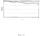
- Fig. 4 shows the WRA signal output for an illustrative 4W pressure deviating tire constellation: Since the wheel individual output signals are based on wheel relative estimations, they contain no information about simultaneous pressure deviations in all tires at the same time. A 4W constellation cannot be recognised based on a WRA alone.
- the WSA module 4 detects changes in the spectral properties of each of the four wheel angular velocity signals.
- the tire pressure has significant influence on the characteristics of the spectrum of the angular velocity signal; however, the road surface and the ambient temperature also have an impact on the angular velocity signal spectrum and should be considered.
- the WSA module 4 By calculating first a parametric model of the wheel velocity spectrum and using the parameters of this model to calculate a spectral shape factor that condenses the different pressure dependent features of the spectrum into one single scalar quantity, the WSA module 4 detects in the illustrated embodiment changes in the tire pressure for each wheel individually.
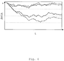
- Fig. 5 , 6 and 7 show the temporal course of illustrative output signals of the WSA module 4 for a 1W pressure deviating tire constellation, a 2W pressure deviating tire constellation, and a 4W pressure deviating tire constellation, respectively.
- Each signal indicates the estimated pressure deviation of a particular tire with regard to the calibration values.
- the WSA module 4 doesn't carry out a normalisation of the signal representing the tire with the least pressure deviation.
- the WSA signals indicate pressure drops of the concerned tires for all of the above constellations; however, the indicated deviation from the "normal" signal levels is not as significant as those of the WRA signals.
- the WSA module 4 is active only for a certain range of vehicle velocities, for example, for the range of 50 to 150 km/h.
- the warning unit 2 obtains data from the WRA module 5 and the WSA module 4. Based on these input data, it detects tire pressure deviations and outputs a warning to the API 3, if a tire pressure deviation is detected. In turn, the API 3 provides the data to external applications.
- WRA and WSA modules shown in figure 1 may be complemented by further modules that are able to infer pressure changes, e.g. by a wheel correlation analysis (WCA) module as known to the skilled person.
- WCA wheel correlation analysis
- Fig. 8 illustrates a data flow diagram reflecting the internal structure of the warning unit 2 of Fig. 1 .
- the warning unit 2 comprises in the illustrated embodiment a load compensation unit 10 which obtains the data from WRA module 5 and WSA module 4. A load compensation of these data before they are provided to the detectors will improve the overall system performance, since load changes affect the roll radius of the wheel and the wheel velocity spectrum.
- load changes without load compensation may produce incorrect pressure deviation warnings.
- the load compensation carried out in load compensation unit 10 is based on the observation that, while an increased load affects the roll radius similarly as a decreased tire pressure, the effect of an increased load on the wheel velocity spectrum is only partly the same as for a pressure decrease. Thus, a comparison of the data delivered from the WRA module 5 and the WSA module 4 in view of the mentioned observation may be able to compensate for load changes.
- the load compensated WSA and WRA signals are input to a plurality of pressure deviation detectors 11.
- Each detector is according to the illustrated embodiment designed and tuned to detect a particular pressure deviating tire constellation and to a particular pressure deviation situation.
- the illustrated embodiment uses five different detector types for the 1W pressure deviating tire constellations (namely puncture, diffusion, flat tire, asymmetric and leakage during calibration detectors); and for each of the 2W, 3W and 4W pressure deviating tire constellations two different detector types (namely puncture and diffusion detectors).
- the puncture detector type operates on a short time scale, typically in minutes, in order to detect rapid pressure deviations in one to four tires.
- the puncture detectors used for 1W, 2W and 3W pressure deviating tire constellations are normally functions of WRA and WSA signals. Outside the active velocity range of WSA, only the WRA signals are used. As mentioned above, the WRA signals are based on four different relative estimations of the roll radii changes which are transformed to indicate pressure drops for each individual tire. Due to this relative nature of the WRA signals the 4W puncture detector is in one embodiment a function of the WSA signals only.
- the WRA and WSA signals represent the estimated pressure deviations with regard to a calibration value, they are denoted in Fig. 9 with ⁇ WRA and ⁇ WSA. An exemplary progression in time of these signals is shown in Fig. 9a and 9d , respectively.
- the 1W puncture detector is based on the difference between the two WRA estimates ⁇ WRA with largest magnitude, ⁇ WRA 1W, which is shown in Fig. 9e .
- this quantity is multiplied by g ( ⁇ WSA).
- Fig. 9c This function is depicted in Fig. 9c.
- Fig. 9b illustrates a typical choice of the function g ( ⁇ ) that returns a value below 1 in case of a small WSA deviation ⁇ WSA (attenuation) and a value above 1 in case of a large WSA deviation ⁇ WSA (amplification), wherein a WSA deviation ⁇ WSA is considered "small” or "large” when it is smaller or larger than a defined deviation value ⁇ , cp.
- Fig. 9a illustrates a typical choice of the function g ( ⁇ ) that returns a value below 1 in case of a small WSA deviation ⁇ WSA (attenuation) and a value above 1 in case of a large WSA deviation ⁇ WS
- I 1 W ⁇ WRA 1 W ⁇ g ⁇ WSA .
- the 1W puncture indicator value is continuously compared to a 1W threshold, T 1W . If I 1W > T 1W , a 1W puncture warning is called.
- the puncture indicator value may be computed as described above. In this case, it might be advantageous to attenuate the indicator value by a fixed multiplicative amount.
- each 1W puncture detector is used for detecting a puncture situation at the front left tire, at the front right tire, at the rear left tire, and at the rear right tire, respectively.
- These 1W detectors differ from each other in that they may be tuned to observe only the WRA and WSA signals corresponding to the respective tire and the deviation of these signals with regard to the WRA and WSA signals corresponding to the other tires. From this, an individual indicator value for each 1W pressure deviating tire constellation may be calculated, such that each 1W detector calls a warning only if a pressure deviation of its corresponding tire occurs.
- the outlined 1W puncture detection approach may also be the basic working principle behind the 2W and 3W puncture detectors.
- the 2W and 3W detectors may be based on the difference between the second and the third largest WRA estimates and the difference between the third largest and the smallest WRA estimates, respectively. If, as in the described embodiment, one detector per 2W and 3W pressure deviating tire constellation is provided, the individual detectors may, as in the 1W case, calculate individual indicators for each pressure deviating tire constellation based on the WRA and WSA signals corresponding to the tires involved in the corresponding pressure deviating tire constellation and their deviation with regard to the other WRA and WSA signals.
- the 4W puncture detector may be based solely on the WSA estimates.
- One embodiment of the detector considers two different criteria in parallel. The first one checks whether the smallest WSA deviation exceeds a threshold, min( I 4 WLev ) > T 4WLev, and the second one that the sum of the WSA deviations for each wheel exceeds another threshold, I 4WSum > T 4WSum .
- the 4W detector may be based on WSA information from a subset of the four wheels, e.g. one of the non-driven wheels or the wheels on the same axle, and use WRA information from this subset to verify that indeed the 4W pressure deviation situation is described by the chosen subset.
- a puncture detector may use other criteria to detect a pressure deviation scenario.
- the diffusion detectors operate on a long time scale, typically hours, to detect slow pressure loss or increase in one to four tires.
- the 1W, 2W and 3W diffusion detectors are functions of the WRA and the WSA signals, while the 4W diffusion detector is a function of the WSA parameters only.
- All these detectors operate according to most embodiments of the invention in the same manner as the corresponding puncture detectors with two major differences in terms of the used WRA and WSA signals: the used WSA and WRA signals adapt slower to reflect the longer time scale and the WSA signals require data from a wider velocity range.
- Flat tire detectors operate on a very short time scale in order to detect rapid and large pressure drops in one tire.
- the flat tire detectors are functions of the WRA signals only.
- the flat tire detectors use information from the most recent WRA estimate to form a 1W flat tire indicator computed as the difference between the two WRA estimates with largest magnitude. If this difference exceeds a threshold for a defined number of consecutive estimations, then a 1W puncture warning is called.
- the 1W asymmetric detectors may complement the puncture and diffusion detectors to enhance the detection performance in asymmetric tire pressure deviation situations.
- An example of such a situation is when the pressure drop in one tire is 15% and in another tire 30%.
- These detectors are functions of the WRA and the WSA signals.
- the 1W asymmetric detectors are based on the WRA estimate with largest magnitude.
- the detector computations are in principle the same as for the 1W puncture and diffusion detectors, but the updates require that both WRA and WSA are active. Detection also requires a distinct deviating pressure indication from both WRA and WSA, such that both subsystems point out the same wheel.
- the computed indicator is also compared to a threshold.
- the leakage during calibration detector detects a continuous pressure drop in one wheel during the system calibration phase. Such a phase is necessary for indirect pressure monitoring systems in order to learn the nominal pressure conditions. Usually, a calibration should be executed whenever a change has been made to the tire pressures, tires or wheels.
- Leakage during calibration is a function of the WRA signals.
- the basic principle of this detector is to monitor the largest roll radius gradient S 1WLeak computed with respect to time and compare this to a threshold for a limited period of time after that calibration was initiated. If S 1WLeak is greater than the threshold during the limited period of time, then a 1W leakage during calibration condition is inferred.
- embodiments of the invention may - in addition to or instead of the described detector types - use any number of different detector types or variations or modifications of the described detector types.
- additional detector types some embodiments of the invention may include detectors for detecting misuse and malfunction situations.
- each detector of each detector type per possible 1W pressure deviating tire constellation.
- the possible 2W, 3W and 4W constellations only puncture and diffusion type detectors are used.
- Other embodiments of the invention use only some, or one, or all of the indicated detector types per possible pressure deviating tire constellation; in some embodiments, more pressure deviating tire constellations than detectors exist, such that at least one detector of any of the above detector types is arranged to detect more than one pressure deviating tire constellation.
- each provided detector may be tuned to detect either all 1W pressure deviating tire constellations, or all 2W constellations, or all 3W constellations, or the 4W constellation. That is, e.g.
- a puncture detector, a diffusion detector, a flat tire detector, an asymmetric detector and a leakage during calibration detector may each be tuned to detect all 1W constellations
- two detector groups are provided, wherein each detector of the first group is tuned to detect a particular pressure deviating tire constellation regardless of the pressure deviation situation, and each detector of the second group is tuned to detect a particular pressure deviation situation, regardless for which pressure deviating tire constellation.
- each detector of the first group is tuned to detect a particular pressure deviating tire constellation regardless of the pressure deviation situation
- each detector of the second group is tuned to detect a particular pressure deviation situation, regardless for which pressure deviating tire constellation.
- other arrangements or combinations of the above arrangements are also possible.
- each detector 11 is optimised for detecting its respective pressure deviating tire constellation in a particular pressure deviation situation and therefore delivers a highly reliable performance.
- the optimisation of the individual detectors 11 of the different detector types for detecting particular pressure deviating tire constellations may in addition to the aspects mentioned above include for example an adaptation of the threshold and indicator parameters to tire specific conditions which are due e.g. to unbalanced load etc. based on data obtained e.g. during the calibration phase or from the vehicle CAN bus.
- the tire pressure monitoring system 1 may further comprise a control unit which is not shown and may for example be implemented as a software routine.
- This control unit determines inter alia whether a detected pressure deviating tire constellation is plausible etc., or if a warning should be reset, e.g. when the present WRA and WSA signals are sufficiently close to the calibration condition.
- the control unit may complement the default evaluation Indicator I > Threshold T of the detectors with a function that guarantees that this condition has been true for a sufficiently long time before a warning is called in order to render the detectors more robust and to avoid nuisance warnings.
- this is implemented using a counter which starts at a predefined value and counts down to zero at a certain rate as long as the condition I > T is true.
- the counter may use a fixed rate or be adaptive. In the latter case, the adaption may, as an example, depend on the difference I-T or on other parameters such as speed and ambient temperature.
- the counter may further be one-directional (i.e. only counting down) or bi-directional (i.e. able to count both up and down). In the latter case, the rate may be different depending on the direction and it may also include some hysteresis means that further control the counting up and down.
- control unit may also be able to adapt different detector parameters of all or of individual detectors in reaction to external influences.
- Data on which the adaptation may be based can be obtained for example from memory module 9 of the tire pressure monitoring system 1.
- the thresholds of the detectors to which the indicator values are compared, or the indicator values themselves may be adapted to temperature changes, driving situations (speed, accelerations, braking etc.), road conditions, quality of input signals, driver inputs, control commands from other systems and ECUs in the vehicle, time since start, time since last calibration etc.
- I default which are e.g. calculated as indicated above
- the functions f(.) and g(.) are simple multiplicative or additive functions, delay operators (e.g. simple delay operators or implemented using counters), logical operators (e.g. if speed ⁇ 10 km/h then 0, else 1), look-up tables, or combinations of the above examples.
- the temperature that matters is the air temperature inside the tires. If a vehicle has no temperature sensors inside the tires, as is often the case for vehicles using indirect tire pressure monitoring systems, information from other available temperature sensors may be used, e.g. from a normal ambient temperature sensor coupled to a car's instrument cluster, or from air temperature sensors in the intake manifold of the vehicle engine. Even information from virtual sensors that estimate the temperature inside the tires using mathematical models of heat build-up during braking and accelerations may be used.
- h(T current ) I when
- ⁇ T limit and 0 otherwise: I modified I default ⁇ h(T current ).
- , for example h( ⁇ T) exp(- ⁇
- the control unit may also activate or deactivate individual detectors, for example in response to an external access.
- the tire pressure monitoring system 1 may be adapted to the requirements of different vehicle models or markets or legislative requirements.
- output data indicating a pressure deviation warning is provided to an output unit 12 which in turn provides the warning to the API 3 of Fig. 1 .
- the output unit 12 is an OR logic.
- any other output unit may be used, provided that it is able to provide the output data to external devices, programs etc. such that a vehicle user may be informed about the pressure deviations, or such that the warning data may be processed otherwise.
- the output data may also include information about a warning level, if the inventive system, method or computer system distinguishes two or more warning levels. If, for example, a pressure drop is slow, a low priority warning may be output in order to inform the user about the current pressure deviation situation and to advice him or her to drive to the next garage; a continuation of the drive for limited time period is not dangerous. In case of a rapid pressure loss, an urgent warning may be given to the user to stop the vehicle immediately. It may be desirable to define a lower threshold for the detection of a low priority warning.
- warning levels are defined differently.
- the warning levels may be assigned to different detector types, i.e. a warning of a particular detector type always produces a warning of a particular level.
- a warning of a particular detector type always produces a warning of a particular level.
- the above flat tire and leakage during calibration detectors may always call high priority warnings
- the puncture, diffusion and asymmetric detectors have mechanisms for evaluating the actual pressure scenario and either call low priority warnings or high priority warnings:
- the diffusion detectors which are based on signals that adapt rather slowly, in one embodiment first set a low priority alarm. If the user continues to drive for a sufficiently long time in this condition or if the pressure deviation exceeds a second level, a high priority warning may be called.
- the warning level may be decided by looking at the difference between the computed puncture and the diffusion indicators. If these indicators are similar enough, a low priority warning is called; otherwise, or if the puncture indicator falls below a second threshold, a high priority warning is set.
- the functionality of deciding the warning level may be implemented for example by the control unit, by the output unit (12) or by the detectors (11).
- the invention allows a precise and reliable detection of an occurring pressure deviating tire constellation in many tire pressure deviation situations.
- the modular arrangement of the detectors renders the inventive system, method and computer program highly flexible since it allows e.g. the specific tuning and optimisation of the single detectors for particular situations and constellations, the optional activation/deactivation etc. of the single detector components, and suitable modifications or adaptations of the different detectors for example to driving situations and ambient conditions.
Landscapes
- Engineering & Computer Science (AREA)
- Mechanical Engineering (AREA)
- Physics & Mathematics (AREA)
- Mathematical Physics (AREA)
- Measuring Fluid Pressure (AREA)
Description
- The invention relates in general to monitoring the tire pressure of a number of tires in a vehicle, and in particular to a system, method and computer program for estimating tire pressure deviations in a plurality of tires in a vehicle.
- Two main issues of automotive design today concern the improvement of driving safety and fuel consumption efficiency. Suboptimal tire pressure may have negative impact on both of these aspects: on the one hand, the contact surface of an incorrectly inflated tire with the street is changed, possibly causing a longer braking distance, worsened side stability and handling of the vehicle and even an increased heat generation between tire and street; on the other hand, the tire pressure directly influences the fuel consumption.
- Therefore, tire pressure monitoring systems are increasingly integrated in the vehicle electronic in order to warn the vehicle driver of any significant deviation from normal tire pressure.
- Tire pressure monitoring systems in general work either directly (i.e. with a tire pressure sensor) or indirectly (i.e. having no tire pressure sensor). Direct monitoring systems are usually very precise, but expensive due to the required additional measuring equipment. Indirect systems are cheaper, but it is naturally more difficult to obtain reliable and useful results.
- Indirect tire pressure monitoring systems mostly use for their estimations signals from existing sensors measuring, for instance, the angular velocity of the wheels, which are used by antilock braking systems (ABS). Based on the angular velocity signals the systems may in particular calculate changes in the wheel radii or observe the spectrum of the angular velocity signals. From this, the system may deduce information about tire pressure derivations. A conventional indirect tire pressure monitoring system is described in
US 6,501,373 B2 . -
DE 10 2005 004 910 A1 relates to a method and a system for indirect tire pressure monitoring of the tires of a vehicle. In particular, it relates to a detector measuring tire circumference differences. - It is an object of the invention to improve the performance of indirect tire pressure monitoring systems.
- The invention achieves this object by providing a method, system and computer program according to the independent claims.
- The dependent claims include further aspects of the invention.
- The invention is described with reference to the accompanying drawings in which:
- Fig. 1
- shows a schematic data flow diagram of a tire pressure monitoring system according to an embodiment of the invention.
- Fig. 2
- shows an illustrative time course of output signals of the WRA module of
Fig. 1 for a 1W pressure deviating tire constellation. - Fig. 3
- shows an illustrative time course of output signals of the WRA module of
Fig. 1 for a 2W pressure deviating tire constellation. - Fig. 4
- shows an illustrative time course of output signals of the WRA module of
Fig. 1 for a 4W pressure deviating tire constellation. - Fig. 5
- shows an illustrative time course of output signals of the WSA module of
Fig. 1 for a 1W pressure deviating tire constellation. - Fig. 6
- shows an illustrative time course of output signals of the WSA module of
Fig. 1 for a 2W pressure deviating tire constellation. - Fig. 7
- shows an illustrative time course of output signals of the WSA module of
Fig. 1 for a 4W pressure deviating tire constellation. - Fig. 8
- shows a schematic data flow diagram of the warning unit of
Fig. 1 . - Fig. 9
- shows six different graphs for illustrating the operation principle of a puncture detector type according to one embodiment of the invention.
- Indirect tire pressure monitoring is a technique known to the person skilled in the art from general knowledge or from the cited reference. Details of this technique are therefore only described as far as they directly concern the invention.
- The invention is provided for use in vehicles having at least two wheels. Vehicles, in general, comprise any type of vehicle having tires, such as cars, bikes, trucks, trailers, and the like. Depending on the number of vehicle tires, a defined number of possible constellations of one or more tires having pressure deviations exist. As an example, fifteen different pressure deviating tire constellations may occur for a vehicle having four tires:
- one single tire may be deviating in pressure, namely the front left (FL) one, the front right (FR) one, the rear left (RL) one, or the rear right (RR) one (thus, in total four different "1W constellations");
- two tires may be deviating in pressure at the same time, namely the two tires of one axle (FL and FR, RL and RR), the two tires of one vehicle side (FL and RL, FR and RR), or the two tires diagonally opposite (FL and RR, FR and RL) (thus, in total six different "2W constellations");
- three tires may be deviating in pressure at the same time, namely all tires except FL, FR, RL or RR (thus, in total four different "3W constellations");
- four tires may be deviating in pressure at the same time (thus, in total one "4W constellation").
- In this context, a "pressure deviation" in a tire is considered to be the case when the tire pressure deviates significantly from the normal tire pressure or the pressure of one or more other tires. Since indirect pressure monitoring systems have no tire pressure measuring possibility, the "normal" tire pressure is usually determined during a calibration phase. Of course, the "significance" of a tire pressure deviation depends on the individual application and vehicle condition; for example, a relative pressure deviation of 20% compared to the normal tire pressure or a pressure difference of 10% between two tires may be considered as significant deviations.
- In order to reliably detect each of the above pressure deviating tire constellations, the invention uses a plurality of pressure deviation detectors.
- The pressure deviation detectors may in one embodiment of the invention be software-implemented or hardware-implemented as separate and individual units which detect pressure deviations for example based on data from sensors measuring the wheel angular velocity (as used e.g. in ABS). In most embodiments, one or more analysis modules pre-process the measuring data before it is provided to the pressure deviation detectors, e.g. using a roll radius based analysis (e.g. wheel radius analysis) and/or wheel spectrum analysis. For example, a wheel radius analysis (WRA) module and/or a wheel spectrum analysis (WSA) module may be used to provide to the pressure deviation detectors data for wheel-relative and/or wheel-individual pressure monitoring. Further data, e.g. relating to vehicle or driving conditions (including e.g. vehicle velocity, ambient temperature, load information, driving state information, etc.), may be also provided to the detectors in some embodiments of the invention; those data may be obtained for example from the vehicle CAN bus via specific modules of an indirect tire pressure monitoring system.
- Mostly, at least one detector is provided for each pressure deviating tire constellation. If so, each of the tire pressure detectors is designed to detect a particular one of the possible pressure deviating tire constellations. The provision of at least one detector per pressure deviating tire constellation allows an optimisation of each detector for detecting a particular pressure deviating tire constellation. Such an optimisation may include for example the provision of the relevant input signals for the specific constellation to the detectors, or the adaptation of detector parameters to specific conditions of the corresponding tires (e.g. the specific tire abrasion, the effects of an unbalanced load etc.). It doesn't matter if the performance of a detector is insufficient to work in relation to other pressure deviating tire constellations than the one it is optimised for, since those other constellations will be detected by their "own" detectors. According to one embodiment of the invention, the detectors call a warning only if they detect the pressure deviating tire constellation they are adapted to, such that the existence of a particular pressure deviating tire constellation can be deduced from the fact that a particular detector calls a warning.
- In some cases, however, there exist more possible pressure deviating tire constellations than detectors, such that at least some of the detectors must be adapted to detect more than one single pressure deviating tire constellation.
- According to further embodiments of the invention, further detectors are provided which are adapted to detect different pressure deviation situations. Examples of different pressure deviation situations comprise rapid pressure loss or rapid pressure increase situations, slow pressure loss or slow pressure increase situations, asymmetric pressure deviation situations, flat tire situations due to rapid and large pressure loss, or leakage situations due to pressure leakage during calibration. Further, pressure deviation situations may include aggravating situations which complicate the correct detection of pressure deviations. Such aggravating situations may for example include situations shortly after the initiation of calibration, or may arise for a mixed tire set with tires of different sizes. Of course, different pressure deviation situations may arise at the same time, for example may a rapid pressure loss situation occur at the same time as a slow pressure increase situation at another tire. Some embodiments of the invention provide detector types which are each optimised to detect a particular pressure deviation situation or a combination of pressure deviation situations.
- The use of different detector types will in some embodiments of the invention enhance the tire pressure estimation performance, for example if one detector of each type is provided for each pressure deviating tire constellation. That is, one detector of each type is adapted to detect the same pressure deviating tire constellation, such that each detector is optimised to detect one particular pressure deviating tire constellation for one particular pressure deviation situation. Since an optimised detector is provided for each pressure deviating tire constellation/deviation situation scenario, pressure deviations will be detected with high reliability.
- Of course, this approach requires a great total number of detectors. For a four wheel vehicle, for example, there exist 15 possible pressure deviating tire constellations; assumed that only three detector types are provided for each constellation, this makes a total number of 45 detectors. It might therefore for some applications be advantageous to use only a small number of different detector types per possible constellation, e.g. one detector type for rapid pressure loss/increase and one type for slow pressure loss/increase; alternatively, different detector types might be provided only for some possible pressure deviating tire constellations. Consequently, some detectors must be able to cope with a number of different pressure deviation situations.
- Another alternative embodiment uses one detector, no matter of which type, per possible pressure deviating tire constellation, and provides in addition to those constellation-optimised detectors one set of detectors of the different types which are not optimised for detecting a specific pressure deviating tire constellation, but only for detecting a specific pressure deviation situation. Results of the one detector group might then be provided to the other detector group, such that the detectors may for example adapt certain detector parameters etc.. This embodiment reduces the total detector number significantly.
- Of course, a combination of the above outlined arrangements may also be provided. For example, some detectors of different types might be provided per possible pressure deviating tire constellation, and some detectors of other types might additionally be used without optimisation to a particular pressure deviating tire constellation. Such an additional detector which is not optimised to a particular pressure deviating tire constellation may be, for instance, a detector for detecting mixed tire sets, since this detector type will normally work reliably without further optimisation to a particular tire constellation.
- In order to render the inventive system, method or computer program more flexible, different detector parameters of individual detectors (e.g. threshold parameters which are for example used for determining if a pressure deviation should cause a warning or not) or other system parameters are - e.g. regularly or in reaction to an external event - adapted to driving or vehicle conditions, ambient temperature, user commands or other external commands etc. according to one embodiment of the invention. For example, a temperature compensation of the detector results by changing detector parameters in dependence on the ambient temperature might improve the performance of the detectors and the overall system. Further, individual detectors might be activated and/or deactivated in order to adapt the tire pressure monitoring to a specific vehicle model, to a specific market or to certain legal regulations.
- In one embodiment a control unit is provided for realising the above features that is implemented, for instance, as a software routine, a CPU or an ECU. The control unit may in one embodiment respond to external requests and/or react to driving or vehicle conditions or detected pressure deviations.
- Another feature the control unit might provide according to one embodiment relates to a plausibility analysis of the detector results. For example, detector results detecting a tire pressure deviation scenario for which they are not optimised or warnings when present WRA and WSA data are sufficiently close to the calibration conditions may be sorted out; also, detector results might be adapted to the current vehicle condition in consideration of vehicle load, weather conditions, calibration situations etc.; or in order to sort out nuisance warnings it may be checked whether a pressure deviating tire constellation has been detected for a sufficiently long time period before calling a warning.
- Further, the control unit may in some embodiments be responsible for forwarding output data to an output unit.
- Of course, the above described features of the control unit might also be implemented by other units, for example the output unit or the detectors themselves.
- An output unit may according to the invention perform the task of providing output data obtained from a control unit or directly from the detectors to an external unit, program or application. The external units or programs may, for instance, store the output data in a memory unit or display the output data to a vehicle user.
- In one embodiment, the output unit is an OR logic which obtains input data from the detectors.
- The provided output data comprise a tire pressure deviation warning, if a pressure deviation is detected. In some embodiments of the invention, the output data further specifies the detected pressure deviating tire constellation, that is, the number and position of pressure deviating tires; some embodiments of the invention additionally provide information about a detected pressure deviation situation. According to some embodiments of the invention, the provided output data comprise information about a warning level that might be determined e.g. by the detectors, by the control unit or by the output unit. A first warning level may indicate e.g. a slow pressure drop which allows a user to drive on for a limited time period without any substantial risk; a second warning level may indicate a rapid or large pressure loss which should cause the user to stop his or her vehicle as soon as possible. Any further warning levels might also be implemented. If no significant pressure deviation is detected, either no data is provided to the output unit, or it is indicated that everything is normal.
- For some embodiments of the invention, there exist vehicle conditions or situations when the tire pressure cannot be monitored, for example outside certain velocity ranges. In such cases, the output unit may output the information that tire pressure monitoring is momentarily inactive.
- A schematic data flow diagram of an embodiment of an inventive tire
pressure monitoring system 1 is shown inFig. 1 . - The tire
pressure monitoring system 1 may for example be a standardised software component which is integrated in an electronic control unit of a vehicle. Thesystem 1 obtains data by means of an application program interface (API) 3. These obtained data may include on the one hand signals from the vehicle CAN bus etc., e.g. describing temperature changes, driving situations (speed, braking...), road conditions or control commands from external devices. In order to make those signals available to the modules ofsystem 1, they are stored according to the illustrated embodiment in amemory unit 9. On the other hand, the obtained data may include measuring data directly obtained from the vehicle's sensors, such as rotational speed sensors (as existent in the vehicle's ABS) which indicate the angular velocity of the rotating wheels. - A
diagnosis control module 8 performs internal system and input signal checks and sets system status and error codes. If a severe error occurs, this module can disable the tire pressure monitoring system. - The obtained data are input to a
signal pre-processing module 7 which pre-filters signals in order to remove disturbances and offsets and pre-computes signals and quantities used by other modules. - Then, the pre-processed signals output by the
signal pre-processing module 7 are input to a unit for roll radius based indirect tire pressure monitoring, here exemplary in form of a wheel radius analysis (WRA)module 5, and to a wheel spectrum analysis (WSA)module 4. Optionally, information is input to theWRA module 5 and theWSA module 4 informing about special driving conditions (e.g. driving with snow chains etc.) detected by a dynamic state detector 6 based on data from thesignal pre-processing module 7 which will be considered for the data analysis. - In essence, a WRA as executed in the
WRA module 5 is based on the fact that the wheel speed of a wheel depends on the respective wheel radius: the wheel speed increases with decreasing wheel radius. Changes in the wheel radii contain information about changes in the tire pressure of the corresponding wheels, but may also reflect vehicle load changes and surface changes or react on driving forces (acceleration, braking, forces in curves etc.). - Based on the wheel angular velocity signals obtained from
module 7, theWRA module 5 estimates changes in the relative wheel radii in one, two and three wheels, but not in all four tires simultaneously since the approach mostly relies on relative wheel radius estimates rather than absolute ones. In order to obtain wheel radius estimates for each wheel separately, the depictedWRA module 5 transforms the relative wheel radii into wheel individual radius estimates and outputs the wheel individual deviation of those estimates from the calibration values. -
Fig. 2 shows the time course of signals output by one embodiment of aWRA module 5 for an illustrative 1W pressure deviating tire constellation. One of the output signals is constantly zero, because a normalisation is carried out by theWRA module 5 such that the signal corresponding to the tire with the least probability of having a pressure drop is set to zero. The other signals indicate estimations of an individual tire's pressure deviation with regard to the calibration values. - As can be seen, the course of one of the signals denotes clearly an increasing estimated pressure deviation of its corresponding tire.
-
Fig. 3 depicts the WRA signal output for an illustrative 2W pressure deviating tire constellation. Again, the two signals corresponding to the concerned tires denote an increasing estimated pressure deviation. - The limits of the WRA evaluation are illustrated in
Fig. 4 which shows the WRA signal output for an illustrative 4W pressure deviating tire constellation: Since the wheel individual output signals are based on wheel relative estimations, they contain no information about simultaneous pressure deviations in all tires at the same time. A 4W constellation cannot be recognised based on a WRA alone. - The
WSA module 4 detects changes in the spectral properties of each of the four wheel angular velocity signals. The tire pressure has significant influence on the characteristics of the spectrum of the angular velocity signal; however, the road surface and the ambient temperature also have an impact on the angular velocity signal spectrum and should be considered. - By calculating first a parametric model of the wheel velocity spectrum and using the parameters of this model to calculate a spectral shape factor that condenses the different pressure dependent features of the spectrum into one single scalar quantity, the
WSA module 4 detects in the illustrated embodiment changes in the tire pressure for each wheel individually. -
Fig. 5 ,6 and7 show the temporal course of illustrative output signals of theWSA module 4 for a 1W pressure deviating tire constellation, a 2W pressure deviating tire constellation, and a 4W pressure deviating tire constellation, respectively. Each signal indicates the estimated pressure deviation of a particular tire with regard to the calibration values. In contrast to theWRA module 5, theWSA module 4 doesn't carry out a normalisation of the signal representing the tire with the least pressure deviation. - As can be seen, the WSA signals indicate pressure drops of the concerned tires for all of the above constellations; however, the indicated deviation from the "normal" signal levels is not as significant as those of the WRA signals.
- In this embodiment, the
WSA module 4 is active only for a certain range of vehicle velocities, for example, for the range of 50 to 150 km/h. - The
warning unit 2 obtains data from theWRA module 5 and theWSA module 4. Based on these input data, it detects tire pressure deviations and outputs a warning to theAPI 3, if a tire pressure deviation is detected. In turn, theAPI 3 provides the data to external applications. - Of course, other embodiments of an inventive tire pressure monitoring system may include further or other components. For example, the configuration of WRA and WSA modules shown in
figure 1 may be complemented by further modules that are able to infer pressure changes, e.g. by a wheel correlation analysis (WCA) module as known to the skilled person. -
Fig. 8 illustrates a data flow diagram reflecting the internal structure of thewarning unit 2 ofFig. 1 . - The
warning unit 2 comprises in the illustrated embodiment aload compensation unit 10 which obtains the data fromWRA module 5 andWSA module 4. A load compensation of these data before they are provided to the detectors will improve the overall system performance, since load changes affect the roll radius of the wheel and the wheel velocity spectrum. - Accordingly, load changes without load compensation may produce incorrect pressure deviation warnings.
- The load compensation carried out in
load compensation unit 10 is based on the observation that, while an increased load affects the roll radius similarly as a decreased tire pressure, the effect of an increased load on the wheel velocity spectrum is only partly the same as for a pressure decrease. Thus, a comparison of the data delivered from theWRA module 5 and theWSA module 4 in view of the mentioned observation may be able to compensate for load changes. - From the
load compensation unit 10, the load compensated WSA and WRA signals are input to a plurality ofpressure deviation detectors 11. Each detector is according to the illustrated embodiment designed and tuned to detect a particular pressure deviating tire constellation and to a particular pressure deviation situation. - Since the illustrated system is used for a four wheel vehicle, fifteen different pressure deviating tire constellations may occur (cp. above).
- In particular, the illustrated embodiment uses five different detector types for the 1W pressure deviating tire constellations (namely puncture, diffusion, flat tire, asymmetric and leakage during calibration detectors); and for each of the 2W, 3W and 4W pressure deviating tire constellations two different detector types (namely puncture and diffusion detectors). In total, 4x5+(6+4+1)x2=42 detectors are in use which are each adapted to detect a particular pressure deviating tire constellation and a particular pressure deviation situation.
- The detector types used in this embodiment and their adaptation to the different pressure deviating tire constellations are illustrated in the following.
- The puncture detector type operates on a short time scale, typically in minutes, in order to detect rapid pressure deviations in one to four tires. The puncture detectors used for 1W, 2W and 3W pressure deviating tire constellations are normally functions of WRA and WSA signals. Outside the active velocity range of WSA, only the WRA signals are used. As mentioned above, the WRA signals are based on four different relative estimations of the roll radii changes which are transformed to indicate pressure drops for each individual tire. Due to this relative nature of the WRA signals the 4W puncture detector is in one embodiment a function of the WSA signals only.
- The operation principle of a puncture type detector for detecting a 1W pressure deviating tire constellation according to one embodiment of the invention is described referring to
Fig. 9 . - Since the WRA and WSA signals represent the estimated pressure deviations with regard to a calibration value, they are denoted in
Fig. 9 with ΔWRA and ΔWSA. An exemplary progression in time of these signals is shown inFig. 9a and 9d , respectively. - The 1W puncture detector is based on the difference between the two WRA estimates ΔWRA with largest magnitude, ΔWRA1W, which is shown in
Fig. 9e . In the active velocity range of WSA, this quantity is multiplied by g(ΔWSA). This function is depicted inFig. 9c. Fig. 9b illustrates a typical choice of the function g(·) that returns a value below 1 in case of a small WSA deviation ΔWSA (attenuation) and a value above 1 in case of a large WSA deviation ΔWSA (amplification), wherein a WSA deviation ΔWSA is considered "small" or "large" when it is smaller or larger than a defined deviation value Δ, cp.Fig. 9a . - The multiplication of g(ΔWSA) and ΔWRA1W forms the 1W puncture indicator I1W shown in
Fig. 9f :
- The 1W puncture indicator value is continuously compared to a 1W threshold, T 1W. If I 1W > T 1W, a 1W puncture warning is called.
- When WRA alone is active, the puncture indicator value may be computed as described above. In this case, it might be advantageous to attenuate the indicator value by a fixed multiplicative amount.
- In the described embodiment, four 1W puncture detectors are used for detecting a puncture situation at the front left tire, at the front right tire, at the rear left tire, and at the rear right tire, respectively. These 1W detectors differ from each other in that they may be tuned to observe only the WRA and WSA signals corresponding to the respective tire and the deviation of these signals with regard to the WRA and WSA signals corresponding to the other tires. From this, an individual indicator value for each 1W pressure deviating tire constellation may be calculated, such that each 1W detector calls a warning only if a pressure deviation of its corresponding tire occurs.
- The outlined 1W puncture detection approach may also be the basic working principle behind the 2W and 3W puncture detectors. However, in contrast to the 1W puncture detector, the 2W and 3W detectors may be based on the difference between the second and the third largest WRA estimates and the difference between the third largest and the smallest WRA estimates, respectively. If, as in the described embodiment, one detector per 2W and 3W pressure deviating tire constellation is provided, the individual detectors may, as in the 1W case, calculate individual indicators for each pressure deviating tire constellation based on the WRA and WSA signals corresponding to the tires involved in the corresponding pressure deviating tire constellation and their deviation with regard to the other WRA and WSA signals.
- The 4W puncture detector may be based solely on the WSA estimates. One embodiment of the detector considers two different criteria in parallel. The first one checks whether the smallest WSA deviation exceeds a threshold, min(I4WLev) > T 4WLev, and the second one that the sum of the WSA deviations for each wheel exceeds another threshold, I 4WSum > T 4WSum. Alternatively, the 4W detector may be based on WSA information from a subset of the four wheels, e.g. one of the non-driven wheels or the wheels on the same axle, and use WRA information from this subset to verify that indeed the 4W pressure deviation situation is described by the chosen subset.
- Other embodiments of a puncture detector may use other criteria to detect a pressure deviation scenario.
- The diffusion detectors operate on a long time scale, typically hours, to detect slow pressure loss or increase in one to four tires. The 1W, 2W and 3W diffusion detectors are functions of the WRA and the WSA signals, while the 4W diffusion detector is a function of the WSA parameters only.
- All these detectors operate according to most embodiments of the invention in the same manner as the corresponding puncture detectors with two major differences in terms of the used WRA and WSA signals: the used WSA and WRA signals adapt slower to reflect the longer time scale and the WSA signals require data from a wider velocity range.
- Flat tire detectors operate on a very short time scale in order to detect rapid and large pressure drops in one tire. The flat tire detectors are functions of the WRA signals only.
- The flat tire detectors use information from the most recent WRA estimate to form a 1W flat tire indicator computed as the difference between the two WRA estimates with largest magnitude. If this difference exceeds a threshold for a defined number of consecutive estimations, then a 1W puncture warning is called.
- The 1W asymmetric detectors may complement the puncture and diffusion detectors to enhance the detection performance in asymmetric tire pressure deviation situations. An example of such a situation is when the pressure drop in one tire is 15% and in another tire 30%. These detectors are functions of the WRA and the WSA signals.
- The 1W asymmetric detectors are based on the WRA estimate with largest magnitude. The detector computations are in principle the same as for the 1W puncture and diffusion detectors, but the updates require that both WRA and WSA are active. Detection also requires a distinct deviating pressure indication from both WRA and WSA, such that both subsystems point out the same wheel. The computed indicator is also compared to a threshold.
- The leakage during calibration detector detects a continuous pressure drop in one wheel during the system calibration phase. Such a phase is necessary for indirect pressure monitoring systems in order to learn the nominal pressure conditions. Usually, a calibration should be executed whenever a change has been made to the tire pressures, tires or wheels.
- Leakage during calibration is a function of the WRA signals.
- The basic principle of this detector is to monitor the largest roll radius gradient S 1WLeak computed with respect to time and compare this to a threshold for a limited period of time after that calibration was initiated. If S 1WLeak is greater than the threshold during the limited period of time, then a 1W leakage during calibration condition is inferred.
- Of course, other embodiments of the invention may - in addition to or instead of the described detector types - use any number of different detector types or variations or modifications of the described detector types. As an example for additional detector types, some embodiments of the invention may include detectors for detecting misuse and malfunction situations.
- For the embodiment of
Fig. 2 there is used, as mentioned above, one detector of each detector type per possible 1W pressure deviating tire constellation. For the possible 2W, 3W and 4W constellations, only puncture and diffusion type detectors are used. Other embodiments of the invention use only some, or one, or all of the indicated detector types per possible pressure deviating tire constellation; in some embodiments, more pressure deviating tire constellations than detectors exist, such that at least one detector of any of the above detector types is arranged to detect more than one pressure deviating tire constellation. For example, each provided detector may be tuned to detect either all 1W pressure deviating tire constellations, or all 2W constellations, or all 3W constellations, or the 4W constellation. That is, e.g. a puncture detector, a diffusion detector, a flat tire detector, an asymmetric detector and a leakage during calibration detector may each be tuned to detect all 1W constellations, a puncture and a diffusion detector may be tuned to detect all 2W constellations, and so on, such that a total number of 5+2+2+2=11 detectors is required. Alternatively, two detector groups are provided, wherein each detector of the first group is tuned to detect a particular pressure deviating tire constellation regardless of the pressure deviation situation, and each detector of the second group is tuned to detect a particular pressure deviation situation, regardless for which pressure deviating tire constellation. Of course, other arrangements or combinations of the above arrangements are also possible. - In the illustrated embodiment, however, each
detector 11 is optimised for detecting its respective pressure deviating tire constellation in a particular pressure deviation situation and therefore delivers a highly reliable performance. The optimisation of theindividual detectors 11 of the different detector types for detecting particular pressure deviating tire constellations may in addition to the aspects mentioned above include for example an adaptation of the threshold and indicator parameters to tire specific conditions which are due e.g. to unbalanced load etc. based on data obtained e.g. during the calibration phase or from the vehicle CAN bus. - The tire
pressure monitoring system 1 may further comprise a control unit which is not shown and may for example be implemented as a software routine. This control unit determines inter alia whether a detected pressure deviating tire constellation is plausible etc., or if a warning should be reset, e.g. when the present WRA and WSA signals are sufficiently close to the calibration condition. Further, the control unit may complement the default evaluation Indicator I > Threshold T of the detectors with a function that guarantees that this condition has been true for a sufficiently long time before a warning is called in order to render the detectors more robust and to avoid nuisance warnings. Preferably, this is implemented using a counter which starts at a predefined value and counts down to zero at a certain rate as long as the condition I > T is true. The counter may use a fixed rate or be adaptive. In the latter case, the adaption may, as an example, depend on the difference I-T or on other parameters such as speed and ambient temperature. The counter may further be one-directional (i.e. only counting down) or bi-directional (i.e. able to count both up and down). In the latter case, the rate may be different depending on the direction and it may also include some hysteresis means that further control the counting up and down. - Preferably, the control unit may also be able to adapt different detector parameters of all or of individual detectors in reaction to external influences. Data on which the adaptation may be based can be obtained for example from
memory module 9 of the tirepressure monitoring system 1. - For example, the thresholds of the detectors to which the indicator values are compared, or the indicator values themselves may be adapted to temperature changes, driving situations (speed, accelerations, braking etc.), road conditions, quality of input signals, driver inputs, control commands from other systems and ECUs in the vehicle, time since start, time since last calibration etc. These can all be described as modifications of the indicator or threshold values realised as functions of basic indicators Idefault (which are e.g. calculated as indicated above) or thresholds Tdefault, i.e. Imodified= f(Idefault) and Tmodified=g(Tdefault). Examples of the functions f(.) and g(.) are simple multiplicative or additive functions, delay operators (e.g. simple delay operators or implemented using counters), logical operators (e.g. if speed < 10 km/h then 0, else 1), look-up tables, or combinations of the above examples.
- It is, according to one embodiment of the invention, further advantageous to use temperature dependent indicators and/or thresholds and/or evaluation rules to improve the performance of the individual detectors and the overall system. The temperature dependence may either be on the current (ambient) temperature, Tcurrent, or on the difference between the current and the temperature during calibration, ΔT= Tcurrent-Tcalibration. The temperature that matters is the air temperature inside the tires. If a vehicle has no temperature sensors inside the tires, as is often the case for vehicles using indirect tire pressure monitoring systems, information from other available temperature sensors may be used, e.g. from a normal ambient temperature sensor coupled to a car's instrument cluster, or from air temperature sensors in the intake manifold of the vehicle engine. Even information from virtual sensors that estimate the temperature inside the tires using mathematical models of heat build-up during braking and accelerations may be used.
- For example, some detectors may be less suitable to use in extreme cold and/or warm conditions. The corresponding detectors can then be modified using a multiplicative function, h(Tcurrent), that is 1 when |Tcurrent| < Tlimit and 0 otherwise: Imodified= Idefault×h(Tcurrent). Another choice of h(.) is to let it be a function of ΔT and to emphasise data coming from similar (temperature) conditions as during the calibration. Typically then 0 ≤ h(ΔT) ≤ 1 and h(0) = 1 and decreasing with increasing |ΔT|, for example h(ΔT) = exp(-γ|ΔT|), where γ is a constant. To use the fact that pressure increases with increasing temperature and vice versa, a non-symmetric function h(ΔT) may be used, for example h(ΔT) = 1-αΔT for ΔT ≥ 0 and = 1 - βΔT for ΔT < 0, where α and β are suitably chosen constants.
- The control unit may also activate or deactivate individual detectors, for example in response to an external access. Thereby, the tire
pressure monitoring system 1 may be adapted to the requirements of different vehicle models or markets or legislative requirements. - When the control unit determines that a plausible pressure deviating tire constellation is detected, output data indicating a pressure deviation warning is provided to an
output unit 12 which in turn provides the warning to theAPI 3 ofFig. 1 . In this embodiment, theoutput unit 12 is an OR logic. Of course, any other output unit may be used, provided that it is able to provide the output data to external devices, programs etc. such that a vehicle user may be informed about the pressure deviations, or such that the warning data may be processed otherwise. - The output data may also include information about a warning level, if the inventive system, method or computer system distinguishes two or more warning levels. If, for example, a pressure drop is slow, a low priority warning may be output in order to inform the user about the current pressure deviation situation and to advice him or her to drive to the next garage; a continuation of the drive for limited time period is not dangerous. In case of a rapid pressure loss, an urgent warning may be given to the user to stop the vehicle immediately. It may be desirable to define a lower threshold for the detection of a low priority warning.
- In other embodiments of the invention the warning levels are defined differently.
- According to one embodiment of the invention, the warning levels may be assigned to different detector types, i.e. a warning of a particular detector type always produces a warning of a particular level. For instance, the above flat tire and leakage during calibration detectors may always call high priority warnings, while the puncture, diffusion and asymmetric detectors have mechanisms for evaluating the actual pressure scenario and either call low priority warnings or high priority warnings: The diffusion detectors, which are based on signals that adapt rather slowly, in one embodiment first set a low priority alarm. If the user continues to drive for a sufficiently long time in this condition or if the pressure deviation exceeds a second level, a high priority warning may be called. For the puncture and asymmetric detectors the warning level may be decided by looking at the difference between the computed puncture and the diffusion indicators. If these indicators are similar enough, a low priority warning is called; otherwise, or if the puncture indicator falls below a second threshold, a high priority warning is set.
- The functionality of deciding the warning level may be implemented for example by the control unit, by the output unit (12) or by the detectors (11).
- Summarising, the invention allows a precise and reliable detection of an occurring pressure deviating tire constellation in many tire pressure deviation situations. The modular arrangement of the detectors renders the inventive system, method and computer program highly flexible since it allows e.g. the specific tuning and optimisation of the single detectors for particular situations and constellations, the optional activation/deactivation etc. of the single detector components, and suitable modifications or adaptations of the different detectors for example to driving situations and ambient conditions.
Claims (13)
- System of estimating tire pressure deviations in a number of tires of a vehicle wherein a plurality of possible constellations of one or more pressure deviating tires exists, the system comprising:a plurality of separate pressure deviation detectors, wherein at least one pressure deviation detector is provided for and assigned to each of the possible pressure deviating tire constellations, and wherein each detector is optimised to detect the pressure deviating tire constellation to which it is assigned;wherein the detectors comprise different detector types which are adapted to detect different pressure deviation situations, the detector types comprising at least one of a puncture detector type for detecting rapid pressure deviations, a diffusion detector type for detecting slow pressure deviations, a flat tire detector type for detecting rapid and large pressure deviations, an asymmetric detector type for detecting asymmetric pressure deviations, a detector type for detecting leakage during calibration, a detector type for detecting different tire sizes; andan output unit (12) which is adapted to provide for a warning if one of the pressure deviation detectors (11) detects one of the pressure deviating tire constellations.
- System according to claim 1, including a unit for determining a warning level in dependence on pressure deviations estimated by the system, wherein, if one of the pressure deviation detectors (11) detects one pressure deviating tire constellation, the output unit (12) additionally provides information specifying the warning level.
- System according to claim 2, wherein the unit for determining the warning level provides a low priority warning level, if an estimated pressure deviation exceeds a first predetermined threshold, and a high priority warning level, if an estimated pressure deviation exceeds a second predetermined threshold which is greater than the first threshold, or if the estimated pressure deviation has exceeded the first threshold for a predetermined time period.
- System according to any of the preceding claims, wherein a unit for roll radius based tire pressure monitoring (5) and/or a wheel spectrum analysis module (4) and/or a wheel correlation module are arranged to provide data to the pressure deviation detectors (11).
- System according to claim 4, comprising a plurality of detectors (11) of different types for each pressure deviating tire constellation.
- System according to any of the preceding claims, further comprising a control unit for activating and/or deactivating any of the pressure deviation detectors (11) and/or for adapting detector parameters in response to vehicle parameters, driving situations, external commands or other external influences.
- System according to any of the preceding claims, further including a load compensation unit (10) connected to load compensate signals before they are provided to the detectors (11).
- Method of estimating tire pressure deviations in a number of tires of a vehicle wherein a plurality of possible constellations of one or more pressure deviating tires exists, the method comprising the steps of:detecting the pressure deviating tire constellations using a plurality of separate pressure deviation detectors (11), wherein at least one pressure deviation detector is provided for and assigned to each of the possible pressure deviating tire constellations, and wherein each detector is optimised to detect the pressure deviating tire constellation to which it is assigned,detecting different deviation situations using a plurality of detectors (11) of different detectors types which are adapted to detect different pressure deviation situations, the detector types comprising at least one of a puncture detector type for detecting rapid pressure deviations, a diffusion detector type for detecting slow pressure deviations, a flat tire detector type for detecting rapid and large pressure deviations, an asymmetric detector type for detecting asymmetric pressure deviations, a detector type for detecting leakage during calibration, a detector type for detecting different tire sizes; andproviding a warning if one of the pressure deviating tire constellations is detected.
- Method of claim 8, comprising the steps of determining a warning level in dependence on estimated pressure deviations and, if one of the pressure deviating tire constellations is detected, additionally providing information specifying the determined warning level.
- Method according to claim 8 or 9, comprising the step of activating and/or deactivating detectors (11) in response to external signals and/or the step of changing detector parameters in response to external requests or driving/vehicle conditions.
- Method of claim 8, wherein the detectors (11) comprise several detectors of different detector types which are each adapted to detect the same pressure deviating tire constellation.
- Method of any of claims 8 to 11, comprising the step of activating and/or deactivating any of the pressure deviation detectors (11) and the step of adapting the detector parameters in response to vehicle parameters, driving situations, external commands or other external influences.
- Computer program of estimating tire pressure deviations in a number of tires of a vehicle wherein a plurality of possible constellations of one or more pressure deviating tires exists, the computer program storing instructions to enable:detecting the pressure deviating tire constellations using a plurality of separate pressure deviation detectors (11), wherein at least one pressure deviation detector is provided for and assigned to each of the possible pressure deviating tire constellations, and wherein each detector is optimised to detect the pressure deviating tire constellation to which it is assigned;detecting different deviation situations using a plurality of detectors (11) of different detectors types which are adapted to detect different pressure deviation situations, the detector types comprising at least one of a puncture detector type for detecting rapid pressure deviations, a diffusion detector type for detecting slow pressure deviations, a flat tire detector type for detecting rapid and large pressure deviations, an asymmetric detector type for detecting asymmetric pressure deviations, a detector type for detecting leakage during calibration, a detector type for detecting different tire sizes; andproviding a warning if one of the pressure deviating tire constellations is detected.
Applications Claiming Priority (1)
| Application Number | Priority Date | Filing Date | Title |
|---|---|---|---|
| PCT/EP2007/002369 WO2008113381A1 (en) | 2007-03-16 | 2007-03-16 | System, method and computer program of estimating tire pressure deviations |
Publications (2)
| Publication Number | Publication Date |
|---|---|
| EP2137012A1 EP2137012A1 (en) | 2009-12-30 |
| EP2137012B1 true EP2137012B1 (en) | 2018-12-26 |
Family
ID=38669935
Family Applications (1)
| Application Number | Title | Priority Date | Filing Date |
|---|---|---|---|
| EP07723346.8A Not-in-force EP2137012B1 (en) | 2007-03-16 | 2007-03-16 | System, method and computer program of estimating tire pressure deviations |
Country Status (5)
| Country | Link |
|---|---|
| US (1) | US9079462B2 (en) |
| EP (1) | EP2137012B1 (en) |
| JP (1) | JP5053393B2 (en) |
| ES (1) | ES2715213T3 (en) |
| WO (1) | WO2008113381A1 (en) |
Cited By (1)
| Publication number | Priority date | Publication date | Assignee | Title |
|---|---|---|---|---|
| DE102022111116A1 (en) | 2022-05-05 | 2023-11-09 | Nira Dynamics Ab | Methods, devices and computer program products for determining the severity of deflation in a tire |
Families Citing this family (11)
| Publication number | Priority date | Publication date | Assignee | Title |
|---|---|---|---|---|
| US10543769B2 (en) * | 2007-03-16 | 2020-01-28 | Nira Dynamics Ab | Method, system and computer program of detecting a tire pressure device |
| JP5491453B2 (en) * | 2011-06-03 | 2014-05-14 | 住友ゴム工業株式会社 | Tire pressure drop detection device, method and program |
| KR20140062141A (en) * | 2011-09-12 | 2014-05-22 | 콘티넨탈 테베스 아게 운트 코. 오하게 | Method for filtering data in a tyre pressure monitoring system for a vehicle |
| JP2014076748A (en) * | 2012-10-11 | 2014-05-01 | Bridgestone Corp | Tire internal pressure alarm system |
| EP2907679B1 (en) * | 2012-10-11 | 2018-04-18 | Bridgestone Corporation | Tire pressure warning system |
| JP5689105B2 (en) * | 2012-11-09 | 2015-03-25 | 住友ゴム工業株式会社 | Tire pressure drop detection device, method and program |
| US9527352B2 (en) * | 2013-06-17 | 2016-12-27 | Infineon Technologies Ag | Indirect tire pressure monitoring systems and methods using multidimensional resonance frequency analysis |
| KR101566748B1 (en) | 2014-06-02 | 2015-11-06 | 현대자동차 주식회사 | Tire Pressure Monitoring System of Motor Driven Vehicle And Method Thereof |
| KR101647696B1 (en) * | 2015-07-13 | 2016-08-11 | 현대오트론 주식회사 | Apparatus and method for monitoring tire pressure using radius analysis |
| US10093138B2 (en) * | 2017-02-14 | 2018-10-09 | Ford Global Technologies, Llc | Monitoring tires of vehicles via personal area networks |
| WO2018234152A1 (en) | 2017-06-19 | 2018-12-27 | Nira Dynamics Ab | MONITORING OF WHEELS IN A VEHICLE |
Family Cites Families (34)
| Publication number | Priority date | Publication date | Assignee | Title |
|---|---|---|---|---|
| US4574267A (en) | 1982-05-06 | 1986-03-04 | Trw Inc. | Tire pressure warning system |
| DE4019501A1 (en) | 1989-09-30 | 1991-04-11 | Lehn F Heinrich | METHOD AND DEVICE FOR VIBRATION MONITORING OF THE WHEEL SYSTEMS OF MOTOR VEHICLES DURING DRIVING |
| JPH0555322A (en) | 1991-08-29 | 1993-03-05 | Mitsubishi Electric Corp | Semiconductor device |
| JP2836652B2 (en) | 1991-11-11 | 1998-12-14 | 株式会社デンソー | Tire pressure detector |
| US5553491A (en) | 1991-11-11 | 1996-09-10 | Nippondenso Co., Ltd. | Tire air pressure detecting device |
| WO1993010431A1 (en) | 1991-11-11 | 1993-05-27 | Nippondenso Co., Ltd. | Tire pneumatic pressure sensor |
| JP3289375B2 (en) * | 1993-03-24 | 2002-06-04 | 株式会社デンソー | VEHICLE VEHICLE VEHICLE ESTIMATION DEVICE AND TIRE CONDITION DETECTOR USING ESTIMATED VEHICLE VEHICLE VEHICLE |
| DE4327492C1 (en) | 1993-08-16 | 1995-02-16 | Daimler Benz Ag | Tire pressure warning procedure |
| US20050192727A1 (en) | 1994-05-09 | 2005-09-01 | Automotive Technologies International Inc. | Sensor Assemblies |
| DE19859225A1 (en) | 1997-12-22 | 1999-07-01 | Aisin Seiki | Tire pressure monitoring method for vehicles |
| JP3594833B2 (en) | 1998-04-02 | 2004-12-02 | 住友ゴム工業株式会社 | Tire air pressure drop warning method and device |
| EP1063106A1 (en) | 1999-06-24 | 2000-12-27 | Carnehammar Lars Bertil | Tyre balancing compositions |
| US6763288B2 (en) | 1999-07-30 | 2004-07-13 | Pirelli Pneumatici S.P.A. | Method and system for monitoring and/or controlling behavior of a vehicle by measuring deformations of its tires |
| US20020024432A1 (en) * | 2000-08-22 | 2002-02-28 | Lite-On Automotive Corporation | Method for monitoring tire pressure of pneumatic tire and device therefor |
| JP3605026B2 (en) * | 2000-10-31 | 2004-12-22 | 住友ゴム工業株式会社 | Tire pressure drop warning device and method |
| DE10060392A1 (en) | 2000-12-05 | 2002-06-20 | Volkswagen Ag | Device and method for monitoring the air pressure in the tires of a motor vehicle |
| ES2271227T3 (en) | 2001-02-06 | 2007-04-16 | Bridgestone Corporation | APPARATUS TO ESTABLISH THE CONDITION TO FIX A TIRE MOUNTED ON RIM AND THE CONDITION TO CORRECT THE OPTIMAL BALANCE, PROVIDING AN APPLIANCE AND A PROCEDURE TO SET A TIRE MOUNTED ON RIM TO THE VEHICLE. |
| DE50113628D1 (en) | 2001-02-28 | 2008-04-03 | Wabco Gmbh | Tire pressure monitoring method and system for vehicles equipped with anti-lock braking systems (ABS systems) |
| US6725136B2 (en) | 2002-04-01 | 2004-04-20 | Robert Bosch Gmbh | Tire pressure and parameter monitoring system and method using accelerometers |
| US6917894B2 (en) | 2002-12-05 | 2005-07-12 | Brian Inge | Tire plus-sizing software program |
| US6822582B2 (en) | 2003-02-25 | 2004-11-23 | Hunter Engineering Company | Radio frequency identification automotive service systems |
| JP3856389B2 (en) | 2003-06-19 | 2006-12-13 | 本田技研工業株式会社 | Tire pressure monitoring device |
| US7627422B2 (en) | 2003-06-24 | 2009-12-01 | At&T Intellectual Property I, Lp | Methods, systems and computer program products for ride matching based on selection criteria and drive characteristic information |
| EP1641639B1 (en) | 2003-07-07 | 2016-09-28 | Nira Dynamics AB | Tire pressure estimation |
| DE10331585A1 (en) | 2003-07-08 | 2005-03-31 | Continental Teves Ag & Co. Ohg | Method for determining the internal pressure of a vehicle tire |
| US6877371B1 (en) * | 2003-11-07 | 2005-04-12 | General Motors Corporation | Method and apparatus for detecting tire pressure |
| JP4086763B2 (en) * | 2003-11-25 | 2008-05-14 | 住友ゴム工業株式会社 | Tire pressure drop detection method and apparatus, and tire decompression determination program |
| DE10360122C5 (en) | 2003-12-20 | 2016-01-07 | Patentportfolio S. à. r. l. | Method for pressure monitoring of motor vehicle tires |
| EP1711355B1 (en) * | 2004-02-02 | 2008-10-15 | Continental Teves AG & Co. oHG | Method for indirect tyre pressure monitoring |
| JP2006015955A (en) | 2004-07-05 | 2006-01-19 | Honda Motor Co Ltd | Tire pressure monitoring system and tire pressure monitoring method |
| US7089099B2 (en) | 2004-07-30 | 2006-08-08 | Automotive Technologies International, Inc. | Sensor assemblies |
| DE102006053826A1 (en) | 2005-11-14 | 2007-06-06 | Continental Teves Ag & Co. Ohg | Method for indirect tire pressure monitoring |
| WO2008113378A1 (en) | 2007-03-16 | 2008-09-25 | Nira Dynamics Ab | Tire pressure classification based tire pressure monitoring |
| ES2679119T3 (en) | 2007-03-16 | 2018-08-22 | Nira Dynamics Ab | Method, system and computer program for pressure estimation |
-
2007
- 2007-03-16 US US12/531,686 patent/US9079462B2/en active Active
- 2007-03-16 EP EP07723346.8A patent/EP2137012B1/en not_active Not-in-force
- 2007-03-16 ES ES07723346T patent/ES2715213T3/en active Active
- 2007-03-16 WO PCT/EP2007/002369 patent/WO2008113381A1/en not_active Ceased
- 2007-03-16 JP JP2009553916A patent/JP5053393B2/en not_active Expired - Fee Related
Non-Patent Citations (1)
| Title |
|---|
| None * |
Cited By (1)
| Publication number | Priority date | Publication date | Assignee | Title |
|---|---|---|---|---|
| DE102022111116A1 (en) | 2022-05-05 | 2023-11-09 | Nira Dynamics Ab | Methods, devices and computer program products for determining the severity of deflation in a tire |
Also Published As
| Publication number | Publication date |
|---|---|
| WO2008113381A1 (en) | 2008-09-25 |
| EP2137012A1 (en) | 2009-12-30 |
| US20100164704A1 (en) | 2010-07-01 |
| ES2715213T3 (en) | 2019-06-03 |
| JP2010521366A (en) | 2010-06-24 |
| US9079462B2 (en) | 2015-07-14 |
| JP5053393B2 (en) | 2012-10-17 |
Similar Documents
| Publication | Publication Date | Title |
|---|---|---|
| US9079462B2 (en) | System, method and computer program of estimating tire pressure deviations | |
| US8525656B2 (en) | Driving condition evaluation device and evaluation method | |
| EP2137010B1 (en) | Tire pressure classification based tire pressure monitoring | |
| EP2226206B1 (en) | Apparatus and method for detecting tire having decreased pressure, and program for detecting tire having decreased pressure | |
| CN108177487B (en) | Tire air pressure monitoring method and device | |
| EP3835161B1 (en) | Vehicle mass estimation device | |
| EP2191987B1 (en) | Apparatus and method for detecting decrease in tire air pressure and program for detecting decrease in tire air pressure | |
| US20100182142A1 (en) | Method, system and computer program of issuing a tire pressure deviation warning | |
| EP2455238B1 (en) | Apparatus and method for detecting decrease in tire air pressure and program for detecting decrease in tire air pressure | |
| EP2137007B1 (en) | Method, system and computer program of detecting a tire pressure deviation | |
| EP2137008B1 (en) | Indirect tire pressure monitoring | |
| EP1223055A2 (en) | Tire pneumatic pressure detector | |
| US8620555B2 (en) | Wheel slip determination for vehicles | |
| US20250222727A1 (en) | Methods, apparatuses and computer program products for determining the severity of a deflation of a tire | |
| EP1371507B1 (en) | Method and apparatus for detecting decrease in tire air-pressure and for judging decompression of tire | |
| JP2009119958A (en) | Vehicle state estimation device | |
| JP2003200724A (en) | Detection method of differential limiting device, method and apparatus for detecting decrease in tire air pressure using the detection method, and program for determining tire pressure reduction | |
| EP1454773A2 (en) | Method and apparatus for alarming decrease in tire air-pressure and program for alarming decrease in tire air-pressure | |
| CN115848073A (en) | Tire pressure monitoring method and device, electronic equipment and storage medium | |
| CN117962515A (en) | Method and device for managing wear of vehicle tires | |
| JP2005300538A (en) | System, method, car, expansion control unit, computer program and computer program preparations |
Legal Events
| Date | Code | Title | Description |
|---|---|---|---|
| PUAI | Public reference made under article 153(3) epc to a published international application that has entered the european phase |
Free format text: ORIGINAL CODE: 0009012 |
|
| 17P | Request for examination filed |
Effective date: 20091021 |
|
| AK | Designated contracting states |
Kind code of ref document: A1 Designated state(s): AT BE BG CH CY CZ DE DK EE ES FI FR GB GR HU IE IS IT LI LT LU LV MC MT NL PL PT RO SE SI SK TR |
|
| R17P | Request for examination filed (corrected) |
Effective date: 20091008 |
|
| DAX | Request for extension of the european patent (deleted) | ||
| STAA | Information on the status of an ep patent application or granted ep patent |
Free format text: STATUS: EXAMINATION IS IN PROGRESS |
|
| 17Q | First examination report despatched |
Effective date: 20161124 |
|
| GRAP | Despatch of communication of intention to grant a patent |
Free format text: ORIGINAL CODE: EPIDOSNIGR1 |
|
| STAA | Information on the status of an ep patent application or granted ep patent |
Free format text: STATUS: GRANT OF PATENT IS INTENDED |
|
| INTG | Intention to grant announced |
Effective date: 20180702 |
|
| GRAS | Grant fee paid |
Free format text: ORIGINAL CODE: EPIDOSNIGR3 |
|
| GRAA | (expected) grant |
Free format text: ORIGINAL CODE: 0009210 |
|
| STAA | Information on the status of an ep patent application or granted ep patent |
Free format text: STATUS: THE PATENT HAS BEEN GRANTED |
|
| AK | Designated contracting states |
Kind code of ref document: B1 Designated state(s): AT BE BG CH CY CZ DE DK EE ES FI FR GB GR HU IE IS IT LI LT LU LV MC MT NL PL PT RO SE SI SK TR |
|
| REG | Reference to a national code |
Ref country code: GB Ref legal event code: FG4D |
|
| REG | Reference to a national code |
Ref country code: CH Ref legal event code: EP |
|
| REG | Reference to a national code |
Ref country code: DE Ref legal event code: R096 Ref document number: 602007057227 Country of ref document: DE |
|
| REG | Reference to a national code |
Ref country code: AT Ref legal event code: REF Ref document number: 1080906 Country of ref document: AT Kind code of ref document: T Effective date: 20190115 |
|
| REG | Reference to a national code |
Ref country code: IE Ref legal event code: FG4D |
|
| PG25 | Lapsed in a contracting state [announced via postgrant information from national office to epo] |
Ref country code: FI Free format text: LAPSE BECAUSE OF FAILURE TO SUBMIT A TRANSLATION OF THE DESCRIPTION OR TO PAY THE FEE WITHIN THE PRESCRIBED TIME-LIMIT Effective date: 20181226 Ref country code: LV Free format text: LAPSE BECAUSE OF FAILURE TO SUBMIT A TRANSLATION OF THE DESCRIPTION OR TO PAY THE FEE WITHIN THE PRESCRIBED TIME-LIMIT Effective date: 20181226 Ref country code: LT Free format text: LAPSE BECAUSE OF FAILURE TO SUBMIT A TRANSLATION OF THE DESCRIPTION OR TO PAY THE FEE WITHIN THE PRESCRIBED TIME-LIMIT Effective date: 20181226 Ref country code: BG Free format text: LAPSE BECAUSE OF FAILURE TO SUBMIT A TRANSLATION OF THE DESCRIPTION OR TO PAY THE FEE WITHIN THE PRESCRIBED TIME-LIMIT Effective date: 20190326 |
|
| REG | Reference to a national code |
Ref country code: NL Ref legal event code: MP Effective date: 20181226 |
|
| REG | Reference to a national code |
Ref country code: LT Ref legal event code: MG4D |
|
| PG25 | Lapsed in a contracting state [announced via postgrant information from national office to epo] |
Ref country code: GR Free format text: LAPSE BECAUSE OF FAILURE TO SUBMIT A TRANSLATION OF THE DESCRIPTION OR TO PAY THE FEE WITHIN THE PRESCRIBED TIME-LIMIT Effective date: 20190327 Ref country code: SE Free format text: LAPSE BECAUSE OF FAILURE TO SUBMIT A TRANSLATION OF THE DESCRIPTION OR TO PAY THE FEE WITHIN THE PRESCRIBED TIME-LIMIT Effective date: 20181226 |
|
| REG | Reference to a national code |
Ref country code: ES Ref legal event code: FG2A Ref document number: 2715213 Country of ref document: ES Kind code of ref document: T3 Effective date: 20190603 |
|
| REG | Reference to a national code |
Ref country code: AT Ref legal event code: MK05 Ref document number: 1080906 Country of ref document: AT Kind code of ref document: T Effective date: 20181226 |
|
| PG25 | Lapsed in a contracting state [announced via postgrant information from national office to epo] |
Ref country code: NL Free format text: LAPSE BECAUSE OF FAILURE TO SUBMIT A TRANSLATION OF THE DESCRIPTION OR TO PAY THE FEE WITHIN THE PRESCRIBED TIME-LIMIT Effective date: 20181226 |
|
| PG25 | Lapsed in a contracting state [announced via postgrant information from national office to epo] |
Ref country code: CZ Free format text: LAPSE BECAUSE OF FAILURE TO SUBMIT A TRANSLATION OF THE DESCRIPTION OR TO PAY THE FEE WITHIN THE PRESCRIBED TIME-LIMIT Effective date: 20181226 Ref country code: PT Free format text: LAPSE BECAUSE OF FAILURE TO SUBMIT A TRANSLATION OF THE DESCRIPTION OR TO PAY THE FEE WITHIN THE PRESCRIBED TIME-LIMIT Effective date: 20190426 Ref country code: PL Free format text: LAPSE BECAUSE OF FAILURE TO SUBMIT A TRANSLATION OF THE DESCRIPTION OR TO PAY THE FEE WITHIN THE PRESCRIBED TIME-LIMIT Effective date: 20181226 Ref country code: IT Free format text: LAPSE BECAUSE OF FAILURE TO SUBMIT A TRANSLATION OF THE DESCRIPTION OR TO PAY THE FEE WITHIN THE PRESCRIBED TIME-LIMIT Effective date: 20181226 |
|
| PG25 | Lapsed in a contracting state [announced via postgrant information from national office to epo] |
Ref country code: EE Free format text: LAPSE BECAUSE OF FAILURE TO SUBMIT A TRANSLATION OF THE DESCRIPTION OR TO PAY THE FEE WITHIN THE PRESCRIBED TIME-LIMIT Effective date: 20181226 Ref country code: IS Free format text: LAPSE BECAUSE OF FAILURE TO SUBMIT A TRANSLATION OF THE DESCRIPTION OR TO PAY THE FEE WITHIN THE PRESCRIBED TIME-LIMIT Effective date: 20190426 Ref country code: RO Free format text: LAPSE BECAUSE OF FAILURE TO SUBMIT A TRANSLATION OF THE DESCRIPTION OR TO PAY THE FEE WITHIN THE PRESCRIBED TIME-LIMIT Effective date: 20181226 Ref country code: SK Free format text: LAPSE BECAUSE OF FAILURE TO SUBMIT A TRANSLATION OF THE DESCRIPTION OR TO PAY THE FEE WITHIN THE PRESCRIBED TIME-LIMIT Effective date: 20181226 |
|
| REG | Reference to a national code |
Ref country code: DE Ref legal event code: R097 Ref document number: 602007057227 Country of ref document: DE |
|
| PG25 | Lapsed in a contracting state [announced via postgrant information from national office to epo] |
Ref country code: DK Free format text: LAPSE BECAUSE OF FAILURE TO SUBMIT A TRANSLATION OF THE DESCRIPTION OR TO PAY THE FEE WITHIN THE PRESCRIBED TIME-LIMIT Effective date: 20181226 Ref country code: MC Free format text: LAPSE BECAUSE OF FAILURE TO SUBMIT A TRANSLATION OF THE DESCRIPTION OR TO PAY THE FEE WITHIN THE PRESCRIBED TIME-LIMIT Effective date: 20181226 Ref country code: AT Free format text: LAPSE BECAUSE OF FAILURE TO SUBMIT A TRANSLATION OF THE DESCRIPTION OR TO PAY THE FEE WITHIN THE PRESCRIBED TIME-LIMIT Effective date: 20181226 |
|
| REG | Reference to a national code |
Ref country code: CH Ref legal event code: PL |
|
| PLBE | No opposition filed within time limit |
Free format text: ORIGINAL CODE: 0009261 |
|
| STAA | Information on the status of an ep patent application or granted ep patent |
Free format text: STATUS: NO OPPOSITION FILED WITHIN TIME LIMIT |
|
| PG25 | Lapsed in a contracting state [announced via postgrant information from national office to epo] |
Ref country code: LU Free format text: LAPSE BECAUSE OF NON-PAYMENT OF DUE FEES Effective date: 20190316 |
|
| 26N | No opposition filed |
Effective date: 20190927 |
|
| REG | Reference to a national code |
Ref country code: BE Ref legal event code: MM Effective date: 20190331 |
|
| PG25 | Lapsed in a contracting state [announced via postgrant information from national office to epo] |
Ref country code: CH Free format text: LAPSE BECAUSE OF NON-PAYMENT OF DUE FEES Effective date: 20190331 Ref country code: LI Free format text: LAPSE BECAUSE OF NON-PAYMENT OF DUE FEES Effective date: 20190331 Ref country code: IE Free format text: LAPSE BECAUSE OF NON-PAYMENT OF DUE FEES Effective date: 20190316 |
|
| PG25 | Lapsed in a contracting state [announced via postgrant information from national office to epo] |
Ref country code: BE Free format text: LAPSE BECAUSE OF NON-PAYMENT OF DUE FEES Effective date: 20190331 Ref country code: SI Free format text: LAPSE BECAUSE OF FAILURE TO SUBMIT A TRANSLATION OF THE DESCRIPTION OR TO PAY THE FEE WITHIN THE PRESCRIBED TIME-LIMIT Effective date: 20181226 |
|
| PG25 | Lapsed in a contracting state [announced via postgrant information from national office to epo] |
Ref country code: TR Free format text: LAPSE BECAUSE OF FAILURE TO SUBMIT A TRANSLATION OF THE DESCRIPTION OR TO PAY THE FEE WITHIN THE PRESCRIBED TIME-LIMIT Effective date: 20181226 |
|
| PG25 | Lapsed in a contracting state [announced via postgrant information from national office to epo] |
Ref country code: MT Free format text: LAPSE BECAUSE OF NON-PAYMENT OF DUE FEES Effective date: 20190316 |
|
| PG25 | Lapsed in a contracting state [announced via postgrant information from national office to epo] |
Ref country code: CY Free format text: LAPSE BECAUSE OF FAILURE TO SUBMIT A TRANSLATION OF THE DESCRIPTION OR TO PAY THE FEE WITHIN THE PRESCRIBED TIME-LIMIT Effective date: 20181226 |
|
| PG25 | Lapsed in a contracting state [announced via postgrant information from national office to epo] |
Ref country code: HU Free format text: LAPSE BECAUSE OF FAILURE TO SUBMIT A TRANSLATION OF THE DESCRIPTION OR TO PAY THE FEE WITHIN THE PRESCRIBED TIME-LIMIT; INVALID AB INITIO Effective date: 20070316 |
|
| PGFP | Annual fee paid to national office [announced via postgrant information from national office to epo] |
Ref country code: GB Payment date: 20220324 Year of fee payment: 16 Ref country code: DE Payment date: 20220322 Year of fee payment: 16 |
|
| PGFP | Annual fee paid to national office [announced via postgrant information from national office to epo] |
Ref country code: FR Payment date: 20220323 Year of fee payment: 16 |
|
| PGFP | Annual fee paid to national office [announced via postgrant information from national office to epo] |
Ref country code: ES Payment date: 20220420 Year of fee payment: 16 |
|
| REG | Reference to a national code |
Ref country code: DE Ref legal event code: R119 Ref document number: 602007057227 Country of ref document: DE |
|
| GBPC | Gb: european patent ceased through non-payment of renewal fee |
Effective date: 20230316 |
|
| PG25 | Lapsed in a contracting state [announced via postgrant information from national office to epo] |
Ref country code: GB Free format text: LAPSE BECAUSE OF NON-PAYMENT OF DUE FEES Effective date: 20230316 |
|
| PG25 | Lapsed in a contracting state [announced via postgrant information from national office to epo] |
Ref country code: GB Free format text: LAPSE BECAUSE OF NON-PAYMENT OF DUE FEES Effective date: 20230316 Ref country code: FR Free format text: LAPSE BECAUSE OF NON-PAYMENT OF DUE FEES Effective date: 20230331 Ref country code: DE Free format text: LAPSE BECAUSE OF NON-PAYMENT OF DUE FEES Effective date: 20231003 |
|
| REG | Reference to a national code |
Ref country code: ES Ref legal event code: FD2A Effective date: 20240429 |
|
| PG25 | Lapsed in a contracting state [announced via postgrant information from national office to epo] |
Ref country code: ES Free format text: LAPSE BECAUSE OF NON-PAYMENT OF DUE FEES Effective date: 20230317 |
|
| PG25 | Lapsed in a contracting state [announced via postgrant information from national office to epo] |
Ref country code: ES Free format text: LAPSE BECAUSE OF NON-PAYMENT OF DUE FEES Effective date: 20230317 |