EP2136455A1 - An electric motor provided with a cooling arrangement - Google Patents
An electric motor provided with a cooling arrangement Download PDFInfo
- Publication number
- EP2136455A1 EP2136455A1 EP08158573A EP08158573A EP2136455A1 EP 2136455 A1 EP2136455 A1 EP 2136455A1 EP 08158573 A EP08158573 A EP 08158573A EP 08158573 A EP08158573 A EP 08158573A EP 2136455 A1 EP2136455 A1 EP 2136455A1
- Authority
- EP
- European Patent Office
- Prior art keywords
- stator
- electric motor
- teeth
- motor according
- winding
- Prior art date
- Legal status (The legal status is an assumption and is not a legal conclusion. Google has not performed a legal analysis and makes no representation as to the accuracy of the status listed.)
- Withdrawn
Links
Images
Classifications
-
- H—ELECTRICITY
- H02—GENERATION; CONVERSION OR DISTRIBUTION OF ELECTRIC POWER
- H02K—DYNAMO-ELECTRIC MACHINES
- H02K3/00—Details of windings
- H02K3/04—Windings characterised by the conductor shape, form or construction, e.g. with bar conductors
- H02K3/24—Windings characterised by the conductor shape, form or construction, e.g. with bar conductors with channels or ducts for cooling medium between the conductors
Definitions
- the invention relates to an electric motor provided with a cooling arrangement.
- a permanent magnet (PM) motor having rectangular stator teeth and a concentrated winding.
- Permanent magnet torque motors are designed for high torque and low speed applications, such as gearless direct drive systems. Due to low speed operation, a high pole number for the motor is possible, while still maintaining a moderate synchronous frequency. The high pole number results in a compact motor because the required yoke thickness becomes thin, the air gap diameter becomes large, and consequently the torque will be high.
- concentrated windings in the stator instead of the traditional distributed windings in which the different phases are crossing each other at the end-winding region.
- the concentrated windings are designed as one coil around one tooth, i.e. tooth coils, which enables very short end-windings and a high fill factor of copper in the stator slot area. The material need is therefore reduced and the heat transfer capability is increased.
- the coils need to be assembled onto the main teeth from the air gap side, i.e. from inside the stator.
- the main teeth should therefore have rectangular shapes.
- the object of the present invention is to provide an electric motor that is suitable for high torque and low speed applications, while taking into consideration other requirements as indicated above.
- an electric motor comprising a rotor, a stator having a plurality of stator teeth having a rectangular cross section, concentrated windings comprising stator winding coils wound on the periphery of the stator teeth, and a stator slot formed between two adjacent stator teeth, characterized in the winding coils comprising a winding of a conductor having a rectangular cross section, whereby an unoccupied space is created in the stator slot between the windings of adjacent teeth, and comprising a cooling arrangement in the unoccupied space of the stator slot.
- a high fill factor can be achieved when rectangular conductors are used as winding in the slots.
- This also provides for improved cooling since high fill factor due to no empty space between the rectangular conductors will result in lower losses and improved thermo-conductivity.
- to provide for cooling in the stator slot offers increased efficiency as compared to the traditional cooling along the yoke or in the housing of the stator, since the hottest spot would be at the end of the winding which would be more efficiently cooled by a cooling arrangement provided in the slot.
- the inventive concept enables efficient cooling of the conductors of the winding, the yoke and the iron core in the stator, resulting in enhanced rated output torque.
- a winding coil of a tooth has an equal number of winding layers along the tooth, thereby forming a rectangular coil. In combination with a rectangular tooth, this will result in that the unoccupied space created in the stator slot will have a trapezoidal cross section, as defined according to another feature.
- the cooling arrangement may comprise means for forced circulation of a cooling fluid in the unoccupied space of the stator slot.
- the cooling arrangement may comprise tubes installed in the unoccupied space of the slot, and that a cooling fluid is circulated in the tubes.
- the cooling arrangement may comprise intermediate teeth installed in the unoccupied space of the slots.
- the intermediate teeth may be solid and of a material having high heat conductivity.
- a solid tooth of for example iron, will in itself contribute to improved cooling due to its capability to dissipate heat.
- the intermediate teeth may be provided with cooling ducts through which a cooling fluid is circulated.
- the intermediate teeth may be designed for mechanical support of the winding coils. Through this, a stabilizing effect on the winding coils is obtained and vibrations are reduced which will increase the life expectancy of the motor.
- intermediate teeth may be trapezoidal in cross section.
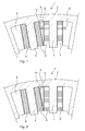
- Fig. 1 is schematically illustrated a coil span and core structure of a PM torque motor.
- the stator core 1 comprises a yoke 2, rectangular stator teeth 4, and a concentrated winding comprising stator coils 6 wound on the periphery of the stator teeth.
- each stator tooth has one coil, i.e. so called tooth coils, forming a so called double layer winding.
- the inventive cooling concept could also be applied to a single layer winding having a coil on every second tooth.
- the winding is made of a rectangular conductor, e.g. copper wire.
- a stator slot 8 Between two adjacent stator teeth 4 is formed a stator slot 8, which is partly occupied by the winding coils 6 of the two adjacent teeth.
- the teeth 4 have a rectangular shape, and since the winding coil 6 of the rectangular conductor has an equal number of windings layers, one or more layers, along the periphery of the individual tooth the winding coils will have a rectangular shape. As a consequence, the winding coils will only partly fill the stator slot, as seen in Fig. 1 . Between two adjacent winding coils there will remain an unoccupied space 10 in the stator slot which will have a trapezoidal shape. In the illustrated first embodiment of Fig. 1 , this trapezoidal unoccupied space is left open and a cooling fluid is circulated in this unoccupied space 10. This is schematically illustrated by the arrows 12. This can be achieved, for example, by letting forced air flow through the motor. Both internal or closed cooling and external cooling are possible, e.g. using a heat exchanger.
- FIG. 2 A second embodiment of the invention is schematically shown in Fig. 2 .
- tubes 14 for a cooling fluid are installed in the unoccupied space 10.
- the tubes will be connected to a cooling system, e.g. including a heat exchanger.
- the fluid in most cases a liquid, is forced to circulate in the tubes.
- the tubes would be in close contact with the winding coils.
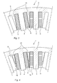
- an intermediate tooth 16 is installed in the unoccupied space 10 of the stator slot 8, between two adjacent teeth 4 and their respective winding coils 6.
- Corresponding intermediate teeth are planned to be installed in all of the stator slots.
- the respective intermediate teeth 16 have a trapezoidal shape in order to fill the unoccupied space.
- the intermediate teeth are solid in order to improve the heat conductivity and promote cooling of the windings and the stator core. They may be of iron or some other material displaying high heat conductivity, but they are not electromagnetically active, or at least this is negligible.
- the intermediate teeth 16 may be made in one piece with the yoke, but other constructions are not excluded.
- the intermediate tooth is provided with a cooling duct 20 inside the tooth.
- a cooling medium is circulated.
- it may be forced air cooling or liquid cooling, with connection to a cooling system, internal or external, including, for example, a heat exchanger.
- the intermediate teeth in Figs. 3 and 4 may also have an additional function as mechanical supports for the winding coils to prevent unfavourable vibrations for example, as well as separating the coils and thereby increasing the fault tolerance of the winding system.
- trapezoidal is here meant having the geometric shape of a trapezoid, i.e. a quadrilateral having only one pair of parallel sides.
- the present invention is suitable for a non-segmented or non-separated core, but not limited thereto.
Landscapes
- Engineering & Computer Science (AREA)
- Power Engineering (AREA)
- Iron Core Of Rotating Electric Machines (AREA)
Abstract
Description
- The invention relates to an electric motor provided with a cooling arrangement. In particular it relates to a permanent magnet (PM) motor having rectangular stator teeth and a concentrated winding.
- Permanent magnet torque motors are designed for high torque and low speed applications, such as gearless direct drive systems. Due to low speed operation, a high pole number for the motor is possible, while still maintaining a moderate synchronous frequency. The high pole number results in a compact motor because the required yoke thickness becomes thin, the air gap diameter becomes large, and consequently the torque will be high. In order to further increase the torque output, it is known to use concentrated windings in the stator instead of the traditional distributed windings in which the different phases are crossing each other at the end-winding region. The concentrated windings are designed as one coil around one tooth, i.e. tooth coils, which enables very short end-windings and a high fill factor of copper in the stator slot area. The material need is therefore reduced and the heat transfer capability is increased.
- Generally, when a high torque is obtained, the requirement for cooling is increased.
- For cost effective manufacturing reasons, the coils need to be assembled onto the main teeth from the air gap side, i.e. from inside the stator. The main teeth should therefore have rectangular shapes.
- The object of the present invention is to provide an electric motor that is suitable for high torque and low speed applications, while taking into consideration other requirements as indicated above.
- According to the present invention is defined an electric motor comprising a rotor, a stator having a plurality of stator teeth having a rectangular cross section, concentrated windings comprising stator winding coils wound on the periphery of the stator teeth, and a stator slot formed between two adjacent stator teeth, characterized in the winding coils comprising a winding of a conductor having a rectangular cross section, whereby an unoccupied space is created in the stator slot between the windings of adjacent teeth, and comprising a cooling arrangement in the unoccupied space of the stator slot.
- Through this invention, a high fill factor can be achieved when rectangular conductors are used as winding in the slots. This also provides for improved cooling since high fill factor due to no empty space between the rectangular conductors will result in lower losses and improved thermo-conductivity. In addition, to provide for cooling in the stator slot offers increased efficiency as compared to the traditional cooling along the yoke or in the housing of the stator, since the hottest spot would be at the end of the winding which would be more efficiently cooled by a cooling arrangement provided in the slot. To summarize, the inventive concept enables efficient cooling of the conductors of the winding, the yoke and the iron core in the stator, resulting in enhanced rated output torque.
- According to a further feature, a winding coil of a tooth has an equal number of winding layers along the tooth, thereby forming a rectangular coil. In combination with a rectangular tooth, this will result in that the unoccupied space created in the stator slot will have a trapezoidal cross section, as defined according to another feature.
- According to one embodiment, the cooling arrangement may comprise means for forced circulation of a cooling fluid in the unoccupied space of the stator slot.
- According to another embodiment, the cooling arrangement may comprise tubes installed in the unoccupied space of the slot, and that a cooling fluid is circulated in the tubes.
- According to a further embodiment, the cooling arrangement may comprise intermediate teeth installed in the unoccupied space of the slots.
- In one alternative, the intermediate teeth may be solid and of a material having high heat conductivity. A solid tooth of for example iron, will in itself contribute to improved cooling due to its capability to dissipate heat.
- In another alternative, the intermediate teeth may be provided with cooling ducts through which a cooling fluid is circulated.
- As a further feature, the intermediate teeth may be designed for mechanical support of the winding coils. Through this, a stabilizing effect on the winding coils is obtained and vibrations are reduced which will increase the life expectancy of the motor.
- Finally, the intermediate teeth may be trapezoidal in cross section.
- By having intermediate teeth, the normal case being one intermediate tooth in each stator slot, it is also possible to achieve improved separation of the winding coils and the risks for possible short circuit currents are reduced. This is an advantage since the neighbouring windings can be of different phases.
- Further features and advantages of the present invention will become apparent from the following detailed description of the invention.
- The present invention will now be described with reference to the accompanying figures, illustrating an example of an embodiment, and in which:
-
Fig. 1 schematically illustrates a first embodiment of a cooling arrangement in an electric motor according to the present invention, -
Fig. 2 schematically illustrates a second embodiment of a cooling arrangement in an electric motor according to the present invention, -
Fig. 3 schematically illustrates a third embodiment of a cooling arrangement in an electric motor according to the present invention, and -
Fig. 4 schematically illustrates a fourth embodiment of a cooling arrangement in an electric motor according to the present invention. - In
Fig. 1 is schematically illustrated a coil span and core structure of a PM torque motor. The stator core 1 comprises ayoke 2,rectangular stator teeth 4, and a concentrated winding comprisingstator coils 6 wound on the periphery of the stator teeth. In the illustrated example, each stator tooth has one coil, i.e. so called tooth coils, forming a so called double layer winding. However, the inventive cooling concept could also be applied to a single layer winding having a coil on every second tooth. The winding is made of a rectangular conductor, e.g. copper wire. Between twoadjacent stator teeth 4 is formed astator slot 8, which is partly occupied by thewinding coils 6 of the two adjacent teeth. - The
teeth 4 have a rectangular shape, and since thewinding coil 6 of the rectangular conductor has an equal number of windings layers, one or more layers, along the periphery of the individual tooth the winding coils will have a rectangular shape. As a consequence, the winding coils will only partly fill the stator slot, as seen inFig. 1 . Between two adjacent winding coils there will remain anunoccupied space 10 in the stator slot which will have a trapezoidal shape. In the illustrated first embodiment ofFig. 1 , this trapezoidal unoccupied space is left open and a cooling fluid is circulated in thisunoccupied space 10. This is schematically illustrated by thearrows 12. This can be achieved, for example, by letting forced air flow through the motor. Both internal or closed cooling and external cooling are possible, e.g. using a heat exchanger. - A second embodiment of the invention is schematically shown in
Fig. 2 . In this figure and the following figures, the same reference numerals as inFig. 1 will be used for the same or corresponding elements. In this embodiment,tubes 14 for a cooling fluid are installed in theunoccupied space 10. The tubes will be connected to a cooling system, e.g. including a heat exchanger. The fluid, in most cases a liquid, is forced to circulate in the tubes. The tubes would be in close contact with the winding coils. - According to a third embodiment of the present invention, illustrated schematically in
Fig. 3 , anintermediate tooth 16 is installed in theunoccupied space 10 of thestator slot 8, between twoadjacent teeth 4 and theirrespective winding coils 6. Corresponding intermediate teeth are planned to be installed in all of the stator slots. Preferably, the respectiveintermediate teeth 16 have a trapezoidal shape in order to fill the unoccupied space. The intermediate teeth are solid in order to improve the heat conductivity and promote cooling of the windings and the stator core. They may be of iron or some other material displaying high heat conductivity, but they are not electromagnetically active, or at least this is negligible. Theintermediate teeth 16 may be made in one piece with the yoke, but other constructions are not excluded. - In a fourth embodiment, schematically shown in
Fig. 4 , the intermediate tooth is provided with a coolingduct 20 inside the tooth. Through this cooling duct, a cooling medium is circulated. For example it may be forced air cooling or liquid cooling, with connection to a cooling system, internal or external, including, for example, a heat exchanger. - The intermediate teeth in
Figs. 3 and 4 may also have an additional function as mechanical supports for the winding coils to prevent unfavourable vibrations for example, as well as separating the coils and thereby increasing the fault tolerance of the winding system. - By the word trapezoidal is here meant having the geometric shape of a trapezoid, i.e. a quadrilateral having only one pair of parallel sides.
- The present invention is suitable for a non-segmented or non-separated core, but not limited thereto.
- The present invention is not limited to the described embodiments, given as examples only, but may be varied and modified in many ways within the scope of the appended patent claims, as will be realized by a person skilled in the art.
Claims (10)
- An electric motor comprising- a rotor,- a stator (1) having a plurality of stator teeth (4) having a rectangular cross section,- concentrated windings comprising stator winding coils (6) wound on the periphery of the stator teeth, and- a stator slot (8) formed between two adjacent stator teeth,characterized in the winding coils (6) comprising a winding of a conductor having a rectangular cross section, whereby an unoccupied space (10) is created in the stator slot (8) between the windings (6) of adjacent teeth (4), and comprising a cooling arrangement (12; 14; 16; 18, 20) in the unoccupied space (10) of the stator slot (8).
- An electric motor according to claim 1, characterized in that the winding coil (6) of a tooth (4) has an equal number of winding layers along the tooth, thereby forming a rectangular coil.
- An electric motor according to any one of claims 1-2, characterized in that the unoccupied space (10) created in the stator slot (8) has a trapezoidal cross section.
- An electric motor according to any one of claims 1-3, characterized in that the cooling arrangement (12) comprises means for forced circulation of a cooling fluid in the unoccupied space (10) of the stator slot (8).
- An electric motor according to any one of claims 1-3, characterized in that the cooling arrangement comprises tubes (14) installed in the unoccupied space (10) of the slot (8), and that a cooling fluid is circulated in the tubes.
- An electric motor according to any one of claims 1-5, characterized in that the cooling arrangement comprises intermediate teeth (16;18) installed in the unoccupied space of the slots.
- An electric motor according to claim 6, characterized in that the intermediate teeth (16) are solid and of a material having a high heat conductivity.
- An electric motor according to claim 6, characterized in that the intermediate teeth (18) are provided with cooling ducts (20) through which a cooling fluid is circulated.
- An electric motor according to any one of claims 6-8, characterized in that the intermediate teeth (16; 18) are designed for mechanical support of the winding coils (6).
- An electric motor according to any one of claims 6-9, characterized in that the intermediate teeth (16; 18) are trapezoidal in cross section.
Priority Applications (1)
| Application Number | Priority Date | Filing Date | Title |
|---|---|---|---|
| EP08158573A EP2136455A1 (en) | 2008-06-19 | 2008-06-19 | An electric motor provided with a cooling arrangement |
Applications Claiming Priority (1)
| Application Number | Priority Date | Filing Date | Title |
|---|---|---|---|
| EP08158573A EP2136455A1 (en) | 2008-06-19 | 2008-06-19 | An electric motor provided with a cooling arrangement |
Publications (1)
| Publication Number | Publication Date |
|---|---|
| EP2136455A1 true EP2136455A1 (en) | 2009-12-23 |
Family
ID=39888668
Family Applications (1)
| Application Number | Title | Priority Date | Filing Date |
|---|---|---|---|
| EP08158573A Withdrawn EP2136455A1 (en) | 2008-06-19 | 2008-06-19 | An electric motor provided with a cooling arrangement |
Country Status (1)
| Country | Link |
|---|---|
| EP (1) | EP2136455A1 (en) |
Cited By (22)
| Publication number | Priority date | Publication date | Assignee | Title |
|---|---|---|---|---|
| JP2011024352A (en) * | 2009-07-16 | 2011-02-03 | Fuji Electric Systems Co Ltd | Stator for rotary electric machine |
| WO2011074973A1 (en) * | 2009-12-16 | 2011-06-23 | Smartmotor As | Electrical machine, rotor for such machine and a method for its manufacturing. |
| EP2498380A1 (en) * | 2011-03-09 | 2012-09-12 | Siemens Aktiengesellschaft | Stator arrangement |
| DE102013216207A1 (en) * | 2013-08-15 | 2015-02-19 | Volkswagen Aktiengesellschaft | Improved heat transfer through optimized sheet metal section of a stator plate of a stator for an electric motor |
| DE102014223421A1 (en) | 2014-11-17 | 2016-05-19 | Robert Bosch Gmbh | Machine component for an electrical machine and an electrical machine with a cooling device |
| WO2016171603A1 (en) * | 2015-04-23 | 2016-10-27 | BAE Systems Hägglunds Aktiebolag | Device for an electric motor |
| CN106655563A (en) * | 2016-12-01 | 2017-05-10 | 华中科技大学 | Motor cooling structure and non-casing motor with same |
| CN106953430A (en) * | 2017-03-08 | 2017-07-14 | 宁波诺丁汉大学 | High Power Density Motor |
| CN107425618A (en) * | 2017-08-28 | 2017-12-01 | 广东美芝制冷设备有限公司 | Stator, motor, compressor and refrigeration plant |
| WO2018157242A1 (en) | 2017-03-02 | 2018-09-07 | Tm4 Inc. | Stator assembly with heat recovery for electric machines |
| CN109391090A (en) * | 2018-09-29 | 2019-02-26 | 宁波诺丁汉大学 | Stator, rotor and motor for heat dissipation |
| CN109599958A (en) * | 2018-12-20 | 2019-04-09 | 江苏大学 | A kind of high reliability, high power density novel permanent-magnet motor |
| CN110048528A (en) * | 2019-04-29 | 2019-07-23 | 西安交通大学 | A kind of motor stator cooling structure based on the heat absorption of low temperature eutectic solid-liquid phase change |
| WO2019198451A1 (en) * | 2018-04-09 | 2019-10-17 | 三菱電機株式会社 | Rotating electric machine and electric power steering device having rotating electric machine |
| WO2019205733A1 (en) * | 2018-04-27 | 2019-10-31 | 江苏大学 | Fault-tolerant modular permanent magnet assisted synchronous reluctance motor and modular winding design method therefor |
| CN110535292A (en) * | 2018-05-23 | 2019-12-03 | 上海鸣志电器股份有限公司 | A kind of low-temperature lifting motor structure |
| CN110971027A (en) * | 2019-12-25 | 2020-04-07 | 山东风发新能源科技有限公司 | Switched Reluctance Motor |
| CN112583149A (en) * | 2020-12-02 | 2021-03-30 | 卧龙电气驱动集团股份有限公司 | High-power-density permanent magnet motor stator and coil inserting method thereof |
| WO2021104549A1 (en) * | 2019-11-28 | 2021-06-03 | Hans Hermann Rottmerhusen | Electronically commutated electric motor |
| WO2021128056A1 (en) * | 2019-12-25 | 2021-07-01 | 山东风发新能源科技有限公司 | Switched reluctance motor |
| US11245309B2 (en) * | 2013-04-03 | 2022-02-08 | Koch Engineered Solutions, Llc | Liquid cooled stator for high efficiency machine |
| EP4083436A1 (en) * | 2021-04-30 | 2022-11-02 | Sanyo Denki Co., Ltd. | Waterproof fan |
Citations (6)
| Publication number | Priority date | Publication date | Assignee | Title |
|---|---|---|---|---|
| US3749950A (en) * | 1972-05-23 | 1973-07-31 | Gen Electric | Dynamoelectric machine having enhanced cooling |
| EP0414507A1 (en) * | 1989-08-21 | 1991-02-27 | Switched Reluctance Drives Ltd | Improvements in electric reluctance machines |
| JP2003164088A (en) * | 2001-11-28 | 2003-06-06 | Nissan Motor Co Ltd | Motor stator structure |
| JP2004104917A (en) * | 2002-09-10 | 2004-04-02 | Nissan Motor Co Ltd | Electric motor stator and electric motor |
| JP2006020490A (en) * | 2004-05-31 | 2006-01-19 | Denso Corp | Rotating electric machine for vehicles having concentrated winding type stator |
| EP1630930A2 (en) * | 2004-08-27 | 2006-03-01 | Caterpillar Inc. | Liquid cooled switched reluctance electric machine |
-
2008
- 2008-06-19 EP EP08158573A patent/EP2136455A1/en not_active Withdrawn
Patent Citations (6)
| Publication number | Priority date | Publication date | Assignee | Title |
|---|---|---|---|---|
| US3749950A (en) * | 1972-05-23 | 1973-07-31 | Gen Electric | Dynamoelectric machine having enhanced cooling |
| EP0414507A1 (en) * | 1989-08-21 | 1991-02-27 | Switched Reluctance Drives Ltd | Improvements in electric reluctance machines |
| JP2003164088A (en) * | 2001-11-28 | 2003-06-06 | Nissan Motor Co Ltd | Motor stator structure |
| JP2004104917A (en) * | 2002-09-10 | 2004-04-02 | Nissan Motor Co Ltd | Electric motor stator and electric motor |
| JP2006020490A (en) * | 2004-05-31 | 2006-01-19 | Denso Corp | Rotating electric machine for vehicles having concentrated winding type stator |
| EP1630930A2 (en) * | 2004-08-27 | 2006-03-01 | Caterpillar Inc. | Liquid cooled switched reluctance electric machine |
Cited By (35)
| Publication number | Priority date | Publication date | Assignee | Title |
|---|---|---|---|---|
| JP2011024352A (en) * | 2009-07-16 | 2011-02-03 | Fuji Electric Systems Co Ltd | Stator for rotary electric machine |
| WO2011074973A1 (en) * | 2009-12-16 | 2011-06-23 | Smartmotor As | Electrical machine, rotor for such machine and a method for its manufacturing. |
| EP2498380A1 (en) * | 2011-03-09 | 2012-09-12 | Siemens Aktiengesellschaft | Stator arrangement |
| CN102684345A (en) * | 2011-03-09 | 2012-09-19 | 西门子公司 | Stator arrangement |
| US8779640B2 (en) | 2011-03-09 | 2014-07-15 | Siemens Aktiengesellschaft | Stator arrangement |
| US11245309B2 (en) * | 2013-04-03 | 2022-02-08 | Koch Engineered Solutions, Llc | Liquid cooled stator for high efficiency machine |
| DE102013216207A1 (en) * | 2013-08-15 | 2015-02-19 | Volkswagen Aktiengesellschaft | Improved heat transfer through optimized sheet metal section of a stator plate of a stator for an electric motor |
| DE102014223421A1 (en) | 2014-11-17 | 2016-05-19 | Robert Bosch Gmbh | Machine component for an electrical machine and an electrical machine with a cooling device |
| WO2016171603A1 (en) * | 2015-04-23 | 2016-10-27 | BAE Systems Hägglunds Aktiebolag | Device for an electric motor |
| EP3286821A4 (en) * | 2015-04-23 | 2018-11-07 | Bae Systems Hägglunds Aktiebolag | Device for an electric motor |
| CN106655563B (en) * | 2016-12-01 | 2018-10-26 | 华中科技大学 | A kind of motor cooling and the inorganic shell motor with the structure |
| CN106655563A (en) * | 2016-12-01 | 2017-05-10 | 华中科技大学 | Motor cooling structure and non-casing motor with same |
| WO2018157242A1 (en) | 2017-03-02 | 2018-09-07 | Tm4 Inc. | Stator assembly with heat recovery for electric machines |
| US11722019B2 (en) | 2017-03-02 | 2023-08-08 | Dana Tm4, Inc. | Stator assembly with heat recovery for electric machines |
| EP3590178A4 (en) * | 2017-03-02 | 2020-12-30 | DANA TM4 Inc. | Stator assembly with heat recovery for electric machines |
| CN110892609A (en) * | 2017-03-02 | 2020-03-17 | Tm4股份有限公司 | Stator assembly with heat recovery for an electric machine |
| CN106953430A (en) * | 2017-03-08 | 2017-07-14 | 宁波诺丁汉大学 | High Power Density Motor |
| CN107425618A (en) * | 2017-08-28 | 2017-12-01 | 广东美芝制冷设备有限公司 | Stator, motor, compressor and refrigeration plant |
| CN107425618B (en) * | 2017-08-28 | 2023-11-14 | 广东美芝制冷设备有限公司 | Stator, motor, compressor and refrigeration equipment |
| JP6612010B1 (en) * | 2018-04-09 | 2019-11-27 | 三菱電機株式会社 | Rotating electric machine and electric power steering apparatus having rotating electric machine |
| WO2019198451A1 (en) * | 2018-04-09 | 2019-10-17 | 三菱電機株式会社 | Rotating electric machine and electric power steering device having rotating electric machine |
| WO2019205733A1 (en) * | 2018-04-27 | 2019-10-31 | 江苏大学 | Fault-tolerant modular permanent magnet assisted synchronous reluctance motor and modular winding design method therefor |
| US11522400B2 (en) | 2018-04-27 | 2022-12-06 | Jiangsu University | Fault-tolerant modular permanent magnet assisted synchronous reluctance motor and modular winding design method |
| CN110535292A (en) * | 2018-05-23 | 2019-12-03 | 上海鸣志电器股份有限公司 | A kind of low-temperature lifting motor structure |
| CN109391090A (en) * | 2018-09-29 | 2019-02-26 | 宁波诺丁汉大学 | Stator, rotor and motor for heat dissipation |
| CN114530991A (en) * | 2018-09-29 | 2022-05-24 | 宁波诺丁汉大学 | Stator and rotor beneficial to heat dissipation |
| CN109599958A (en) * | 2018-12-20 | 2019-04-09 | 江苏大学 | A kind of high reliability, high power density novel permanent-magnet motor |
| CN110048528A (en) * | 2019-04-29 | 2019-07-23 | 西安交通大学 | A kind of motor stator cooling structure based on the heat absorption of low temperature eutectic solid-liquid phase change |
| WO2021104549A1 (en) * | 2019-11-28 | 2021-06-03 | Hans Hermann Rottmerhusen | Electronically commutated electric motor |
| WO2021128056A1 (en) * | 2019-12-25 | 2021-07-01 | 山东风发新能源科技有限公司 | Switched reluctance motor |
| CN110971027A (en) * | 2019-12-25 | 2020-04-07 | 山东风发新能源科技有限公司 | Switched Reluctance Motor |
| CN110971027B (en) * | 2019-12-25 | 2025-07-18 | 山东风发新能源科技有限公司 | Switched reluctance motor |
| CN112583149A (en) * | 2020-12-02 | 2021-03-30 | 卧龙电气驱动集团股份有限公司 | High-power-density permanent magnet motor stator and coil inserting method thereof |
| EP4083436A1 (en) * | 2021-04-30 | 2022-11-02 | Sanyo Denki Co., Ltd. | Waterproof fan |
| US12176785B2 (en) | 2021-04-30 | 2024-12-24 | Sanyo Denki Co., Ltd. | Waterproof fan |
Similar Documents
| Publication | Publication Date | Title |
|---|---|---|
| EP2136455A1 (en) | An electric motor provided with a cooling arrangement | |
| RU2649972C2 (en) | Pole shoe cooling gap for axial motor | |
| CN105308832B (en) | Liquid-cooled stators for high-efficiency machinery | |
| US11496025B2 (en) | Stator for an electric rotating machine | |
| US20070273221A1 (en) | Brushless motor | |
| US7812498B2 (en) | Stator of electric rotating machine and electric rotating machine | |
| US20160028284A1 (en) | Electric machine | |
| US20240146134A1 (en) | Stator of an electric flux machine, and axial flux machine | |
| CN113841320A (en) | Stator for axial flux machine | |
| FI128650B (en) | A stator of an electric machine and an electric machine | |
| JP6469964B2 (en) | Permanent magnet rotating electric machine | |
| JP2015177723A (en) | Rotating electric machine | |
| US20240195253A1 (en) | Stator of an electric axial flux machine, and axial flux machine | |
| JP2008253014A (en) | High voltage rotating electrical machine | |
| US20220311289A1 (en) | Machine with toroidal winding | |
| JP6591198B2 (en) | Rotating electric machine stator | |
| JP2016129447A (en) | Rotary electric machine | |
| US20230318382A1 (en) | Stator and motor | |
| JPWO2022185841A5 (en) | ||
| JP6169496B2 (en) | Permanent magnet rotating electric machine | |
| CN115315882A (en) | Stator and rotating electrical machine | |
| WO2023106338A1 (en) | Motor | |
| JP2004282858A (en) | Stator and rotating machine using the same | |
| JP2006320104A (en) | Coil cooling structure of electric motor | |
| CN111092531A (en) | Motor, and electric fan and electric dust collector using the same |
Legal Events
| Date | Code | Title | Description |
|---|---|---|---|
| PUAI | Public reference made under article 153(3) epc to a published international application that has entered the european phase |
Free format text: ORIGINAL CODE: 0009012 |
|
| 17P | Request for examination filed |
Effective date: 20080619 |
|
| AK | Designated contracting states |
Kind code of ref document: A1 Designated state(s): AT BE BG CH CY CZ DE DK EE ES FI FR GB GR HR HU IE IS IT LI LT LU LV MC MT NL NO PL PT RO SE SI SK TR |
|
| AX | Request for extension of the european patent |
Extension state: AL BA MK RS |
|
| AKX | Designation fees paid |
Designated state(s): AT BE BG CH CY CZ DE DK EE ES FI FR GB GR HR HU IE IS IT LI LT LU LV MC MT NL NO PL PT RO SE SI SK TR |
|
| STAA | Information on the status of an ep patent application or granted ep patent |
Free format text: STATUS: THE APPLICATION HAS BEEN WITHDRAWN |
|
| 18W | Application withdrawn |
Effective date: 20131119 |