EP2136367B1 - Multilayer optical disk recording apparatus and multilayer optical disk reproducing apparatus - Google Patents
Multilayer optical disk recording apparatus and multilayer optical disk reproducing apparatus Download PDFInfo
- Publication number
- EP2136367B1 EP2136367B1 EP09251206A EP09251206A EP2136367B1 EP 2136367 B1 EP2136367 B1 EP 2136367B1 EP 09251206 A EP09251206 A EP 09251206A EP 09251206 A EP09251206 A EP 09251206A EP 2136367 B1 EP2136367 B1 EP 2136367B1
- Authority
- EP
- European Patent Office
- Prior art keywords
- recording
- optical disk
- multilayer optical
- laser beams
- recording layer
- Prior art date
- Legal status (The legal status is an assumption and is not a legal conclusion. Google has not performed a legal analysis and makes no representation as to the accuracy of the status listed.)
- Active
Links
- 230000003287 optical effect Effects 0.000 title claims abstract description 92
- 238000012545 processing Methods 0.000 claims description 24
- 230000005540 biological transmission Effects 0.000 claims description 16
- 238000000034 method Methods 0.000 claims description 15
- 230000007547 defect Effects 0.000 claims description 4
- 238000011144 upstream manufacturing Methods 0.000 claims 3
- 239000010410 layer Substances 0.000 description 184
- 230000002093 peripheral effect Effects 0.000 description 29
- 238000010586 diagram Methods 0.000 description 12
- 239000002356 single layer Substances 0.000 description 10
- 239000002355 dual-layer Substances 0.000 description 9
- 239000011229 interlayer Substances 0.000 description 6
- 238000005516 engineering process Methods 0.000 description 5
- 238000007796 conventional method Methods 0.000 description 4
- 230000000694 effects Effects 0.000 description 4
- 238000011161 development Methods 0.000 description 3
- 230000003111 delayed effect Effects 0.000 description 2
- 238000001514 detection method Methods 0.000 description 2
- 238000009826 distribution Methods 0.000 description 2
- 230000004044 response Effects 0.000 description 2
- 230000008054 signal transmission Effects 0.000 description 2
- 238000003860 storage Methods 0.000 description 2
- 230000006835 compression Effects 0.000 description 1
- 238000007906 compression Methods 0.000 description 1
- 239000004020 conductor Substances 0.000 description 1
- 238000013461 design Methods 0.000 description 1
- 230000001678 irradiating effect Effects 0.000 description 1
- 238000004519 manufacturing process Methods 0.000 description 1
- 238000005459 micromachining Methods 0.000 description 1
- 238000012986 modification Methods 0.000 description 1
- 230000004048 modification Effects 0.000 description 1
- 238000001228 spectrum Methods 0.000 description 1
- 239000002344 surface layer Substances 0.000 description 1
- 238000012546 transfer Methods 0.000 description 1
Images


Classifications
-
- G—PHYSICS
- G11—INFORMATION STORAGE
- G11B—INFORMATION STORAGE BASED ON RELATIVE MOVEMENT BETWEEN RECORD CARRIER AND TRANSDUCER
- G11B7/00—Recording or reproducing by optical means, e.g. recording using a thermal beam of optical radiation by modifying optical properties or the physical structure, reproducing using an optical beam at lower power by sensing optical properties; Record carriers therefor
- G11B7/007—Arrangement of the information on the record carrier, e.g. form of tracks, actual track shape, e.g. wobbled, or cross-section, e.g. v-shaped; Sequential information structures, e.g. sectoring or header formats within a track
- G11B7/00745—Sectoring or header formats within a track
-
- G—PHYSICS
- G11—INFORMATION STORAGE
- G11B—INFORMATION STORAGE BASED ON RELATIVE MOVEMENT BETWEEN RECORD CARRIER AND TRANSDUCER
- G11B7/00—Recording or reproducing by optical means, e.g. recording using a thermal beam of optical radiation by modifying optical properties or the physical structure, reproducing using an optical beam at lower power by sensing optical properties; Record carriers therefor
- G11B7/08—Disposition or mounting of heads or light sources relatively to record carriers
- G11B7/085—Disposition or mounting of heads or light sources relatively to record carriers with provision for moving the light beam into, or out of, its operative position or across tracks, otherwise than during the transducing operation, e.g. for adjustment or preliminary positioning or track change or selection
- G11B7/08505—Methods for track change, selection or preliminary positioning by moving the head
- G11B7/08511—Methods for track change, selection or preliminary positioning by moving the head with focus pull-in only
-
- G—PHYSICS
- G11—INFORMATION STORAGE
- G11B—INFORMATION STORAGE BASED ON RELATIVE MOVEMENT BETWEEN RECORD CARRIER AND TRANSDUCER
- G11B7/00—Recording or reproducing by optical means, e.g. recording using a thermal beam of optical radiation by modifying optical properties or the physical structure, reproducing using an optical beam at lower power by sensing optical properties; Record carriers therefor
- G11B7/12—Heads, e.g. forming of the optical beam spot or modulation of the optical beam
- G11B7/14—Heads, e.g. forming of the optical beam spot or modulation of the optical beam specially adapted to record on, or to reproduce from, more than one track simultaneously
-
- G—PHYSICS
- G11—INFORMATION STORAGE
- G11B—INFORMATION STORAGE BASED ON RELATIVE MOVEMENT BETWEEN RECORD CARRIER AND TRANSDUCER
- G11B7/00—Recording or reproducing by optical means, e.g. recording using a thermal beam of optical radiation by modifying optical properties or the physical structure, reproducing using an optical beam at lower power by sensing optical properties; Record carriers therefor
- G11B2007/0003—Recording, reproducing or erasing systems characterised by the structure or type of the carrier
- G11B2007/0009—Recording, reproducing or erasing systems characterised by the structure or type of the carrier for carriers having data stored in three dimensions, e.g. volume storage
- G11B2007/0013—Recording, reproducing or erasing systems characterised by the structure or type of the carrier for carriers having data stored in three dimensions, e.g. volume storage for carriers having multiple discrete layers
-
- G—PHYSICS
- G11—INFORMATION STORAGE
- G11B—INFORMATION STORAGE BASED ON RELATIVE MOVEMENT BETWEEN RECORD CARRIER AND TRANSDUCER
- G11B7/00—Recording or reproducing by optical means, e.g. recording using a thermal beam of optical radiation by modifying optical properties or the physical structure, reproducing using an optical beam at lower power by sensing optical properties; Record carriers therefor
- G11B7/24—Record carriers characterised by shape, structure or physical properties, or by the selection of the material
- G11B7/2403—Layers; Shape, structure or physical properties thereof
- G11B7/24035—Recording layers
- G11B7/24038—Multiple laminated recording layers
Definitions
- the present invention relates to an optical disk recording apparatus and optical disk reproducing apparatus and, more particularly, to a multilayer optical disk recording apparatus and multilayer optical disk reproducing apparatus capable of high-speed recording of a multilayer optical disk.
- JP-A-2006-164374 discloses a method for irradiating two laser beams on a plurality of recording layers within a disk via one objective lens at the same time.
- the storage capacity of one optical disk largely increases with the adoption of blue laser. Accordingly, the processing time required to be recorded and reproduced also increases as much as an increased storage capacity.
- the high-speed recording and reproducing technological development such as sixfold speed is being promoted along with a larger capacity of the optical disk.
- a current system configuration is considered to have a limit of about twelvefold speed from the limitations of the disk rotation number.
- JP-A-2006-164374 For this high-speed technology, disclosed is a multilayer simultaneous recording technology in JP-A-2006-164374 .
- the management of recording areas is important in the system wherein this multi-recording layer simultaneous recording format and a conventional single-layer recording format mixedly exist.
- JP-A-2006-268952 discloses a multilayer optical disk recording apparatus in which a plurality of laser beams are simultaneously emitted from different light sources and focused onto a multilayer optical dish.
- the laser beams are focused onto the disk with the objective lens being driven so that a first beam is focused on a first recording layer, a second beam focused on a second recording layer, etc.
- a multilayer optical disk recording apparatus for recording information on a multilayer optical disk having a plurality of recording layers in a thickness direction, comprising an optical pickup that emits N (N represents an integer of two or more) laser beams of the same wavelength, the apparatus being adapted to cause the optical pickup: to emit the N laser beams at the same time;
- a multilayer optical disk reproducing apparatus for reproducing information recorded on a multilayer optical disk having a plurality of recording layers in a thickness direction, comprising an optical pickup that emits N (N represents an integer of two or more) laser beams of the same wavelength, the apparatus being adopted to cause the optical pickup: to emit the N laser beams at the same time;
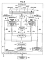
- FIG. 1 is a block diagram illustrating one embodiment of a multilayer optical disk recording and reproducing apparatus according to the present invention.
- Reference numeral 1 denotes a disk
- 2 denotes a motor
- 3 denotes a servo drive circuit
- 4 denotes a pickup
- 5 denotes a laser drive circuit
- 6 denotes a photodetector circuit
- 7 denotes a servo circuit
- 8 denotes a buffer memory
- 9 denotes a reproducing signal processing circuit
- 10 denotes a recording signal processing circuit
- 110 denotes an L0 recording layer
- 111 denotes an L1 recording layer
- 112 denotes an L2 recording layer
- 113 denotes an L3 recording layer
- 121 denotes a first laser beam
- 122 denotes a second laser beam
- 13 denotes a signal processing circuit
- 14 denotes an optical disk recording and reproducing apparatus
- 15 denotes a drive control device.
- a 4-layer disk is used as the disk 1, and the first laser beam 121 and the second laser beam 122 are emitted so as to correspond to a dual-layer simultaneous recording operation.
- the optical disk recording and reproducing apparatus 14 Only the first laser beam 121 is normally irradiated from the pickup 4.
- the disk 1 When a BD-R disk 1 as a one-time writing disk in a Blu-Ray system is inserted into the optical disk recording and reproducing apparatus 14, the disk 1 is rotated by the motor 2, the servo circuit 7 and the servo drive circuit 3, and the first laser beam 121 that is controlled to a power value for reproduction is irradiated on a recording surface of the disk 1 from the pickup 4.
- the photodetector circuit 6 detects the intensity of light reflected by the disk 1 of the first laser beam 121 to thereby obtain reproducing digital signal trains.
- the reproducing digital signal trains are decoded using the buffer memory 8 and the reproducing signal processing circuit 9, and information of the control signals recorded on the disk 1 is read out, thereby discriminating a disk medium.
- the optical disk recording and reproducing apparatus 14 is in an operation standby state. Thereafter, the optical disk recording and reproducing apparatus 14 is controlled in a recording or reproducing state of data, for example, based on instructions of the drive control device 15 configured by a host computer.
- the servo drive circuit 3 rotates the disk 1 at a predetermined speed, and at the same time, performs processings such as a focus control, tracking control, and optimum recording power control of the first laser beam 121.
- digital data strings W1 outputted from the recording signal processing circuit 10 within the signal processing circuit 13 are transmitted to the laser drive circuit 5.
- the laser drive circuit 5 sets a power value of a recording data signal to a predetermined value, and sequentially records information data on a track of the disk 1.
- the servo drive circuit 3 rotates the disk 1 at a predetermined speed, and at the same time, performs processings such as a focus control and tracking control of the first laser beam 121, whereby recorded reproduction digital data strings R1 are sequentially reproduced.
- the number of rotations of the motor 2 is controlled to 4860 rotations per minute using the servo drive circuit 3.
- the photodetector circuit 6 detects reflected light of the first laser beam 121 outputted from the pickup 4. Further, the photodetector circuit 6 scans one recording track that is spirally formed from an inner periphery to outer periphery of the disk 1, and obtains the reproduction digital data strings R1.
- the reproduction speed at the outer peripheral portion of the disk 1 is the fastest sixfold speed, and the signal frequency to be reproduced is a repeating signal with 2T (T is a bit period) of 99 MHz.
- the reproduction speed at the inner peripheral portion of the disk 1, since the number of rotations of the motor 2 is 4860 rotations per minute is a two and half-fold speed.
- the number of a maximum double speed is thus determined by the number of rotations of the disk 1. For example, when the allowable number of rotations of the motor 2 is determined to be 10000 rotations or less per minute (9720 rotations per minute),the number of the maximum double speed is fivefold speed at the inner peripheral surface, and is twelvefold speed at the outer peripheral surface, respectively.
- the data is reproduced by the operations of a PLL circuit that detects a transmission clock from among the reproduction digital signal trains R1 as well as by those of a partial response reproducing circuit that adapts a transmission system to a partial response.
- the reproduced data is once stored in the buffer memory 8.
- the data stored in the buffer memory 8 is sequentially read out by the reproducing signal processing circuit 9, and the information data recorded on the disk 1 is reproduced using circuit operations (not shown) of a synchronization signal detection circuit, a demodulation circuit, and an error detecting and correcting circuit.
- the speed equivalent to twelvefold speed can be realized by the adoption of a micromachining process in relation to the operation speed of the above-described circuits.
- a number of signals such as RF signals or servo signals as signals outputted from the photodetector circuit 6 within the pickup 4 are here required to be transmitted to the circuit board.
- the pickup 4 and the circuit board are connected to each other, in many cases, by a conductor wiring printed on a flexible sheet.
- the wiring using this flexible sheet is suitable for the above-described connection between the moving part and the fixed part; however, has a fault that when a wiring interval is narrowed, capacitance between wirings increases, and further, this capacitance between wirings is resonated with the inductance of transmission line to thereby narrow the transmission band width.
- the transmission band width is on the order of 150 MHz depending on the design (wiring length, wiring width, and wiring interval) of the flexible sheet.
- This transmission band width is equal to the frequency spectrum distribution band width in the sixfold speed using the above-described Blu-Ray system, and therefore, the transfer speed of an eightfold speed or more is hard to be realized using a conventional apparatus configuration. Accordingly, based on frequency characteristics of this transmission circuit, the sixfold speed is the reproduction speed that can be realized with stable operations in a conventional system configuration.
- the following method as shown in FIG. 1 is used in the present invention. That is, during the recording and reproducing operations, the first laser beam 121 and the second laser beam 122 are emitted, and both of the operations are performed on two recording layers at the same time, thereby realizing a speeding up being twice as fast as the conventional speed.
- FIG. 2 illustrates an example of an arrangement of two laser beams according to the present invention.
- the first laser beam 121 and the second laser beam 122 are formed in line in a recording track direction of the disk 1.
- the drive control device 15 shown in FIG. 1 when commanding a dual-layer simultaneous recording mode, causes the recording signal processing circuit 10 to operate at a speed being twice as fast as the conventional speed as well as to output two recording signal data strings W1 and W2 at the same time, and causes the optical pickup 4 to emit the first laser beam 121 and the second laser beam 122, respectively.
- Each of the recording signal data strings W1 and W2 at this time has the same data transmission speed as that at the time of a conventional single layer recording operation.
- the servo drive circuit 3 performs a focus control such that the first laser beam 121 focuses on the L0 recording layer 110 and the second laser beam 122 focuses on the L2 recording layer 112.
- the first laser beam 121 sequentially records information data on a recording track of the L0 recording layer 110 and the second laser beam 122 records information data on a recording track of the L2 recording layer 112.
- each laser beam performs an interlayer jump as much as one recording layer and performs a focus adjustment.
- the first laser beam 121 records the information data on the recording track of the L1 recording layer 111 and the second laser beam 122 records the information data on the recording track of the L3 recording layer 113.
- FIG. 3 illustrates one example of a physical address of the multilayer optical disk used in the present embodiment.
- the disk 1 has 6 recording layers, and the physical address is configured so as to increase in the order corresponding to the L0 recording layer inner periphery, the L0 recording layer outer periphery, the L1 recording layer outer periphery, the L1 recording layer inner periphery, the L2 recording layer inner periphery, the L2 recording layer outer periphery, the L3 recording layer outer periphery, the L3 recording layer inner periphery, the L4 recording layer inner periphery, the L4 recording layer outer periphery, the L5 recording layer outer periphery, and the L5 recording layer inner periphery.
- the layer number is imparted to a high-order position of each address, and further, the same physical address is imparted to the same radius position of the L0 recording layer 110, the L2 recording layer 112, and the L4 recording layer 114 as well as that of the L1 recording layer 111, the L3 recording layer 113, and the L5 recording layer 115.
- the layer number is here imparted to the high-order position of each address; however, the present embodiment is not limited thereto.
- the present invention exerts the following effects.
- the dual-layer simultaneous recording operation is performed alternately in the same radius position as described above.
- the recording layer is moved at the time when a recordable region of each recording layer disappears, the interlayer jump is required to be performed as much as two recording layers in the case of performing the simultaneous recording operation in adjacent recording layers.
- each laser beam may perform the interlayer jump as much as one recording layer, a stable and rapid movement can be performed.
- the data transmission to the second laser beam 122 may be delayed as compared with that to the first laser beam 121 as much as a distance between two laser beams.
- the data transmission to the second laser beam 122 may be delayed as compared with that to the first laser beam 121.
- the first laser beam 121 and the second laser beam 122 are each set to reproducing laser power.
- the first laser beam 121 irradiates the L0 recording layer 110
- the second laser beam 122 irradiates the L2 recording layer 112 for the simultaneous reproduction, thereby obtaining the reproduction signal trains R1 and R2.
- each laser beam performs the interlayer jump as much as one recording layer and performs the focus adjustment.
- the first laser beam 121 irradiates a recording track of the L1 recording layer 111, and meanwhile, the second laser beam 122 irradiates a recording track of the L3 recording layer 113 for the simultaneous reproduction from the outer peripheral surface to the inner peripheral surface.
- the dual-layer simultaneous recording operation since a series of information data blocks is divided into two data strings W1 and W2 to be recorded, two data strings R1 and R2 are reproduced at the same time to be sequentially stored in the buffer memory 8 in parallel during the reproducing operation.
- the data address number is detected based on data ID codes of the data to be rearranged to the original series data strings based on these signals.
- the signal processing circuit 13 After the determination of the data order, the signal processing circuit 13 performs a double speed operation. Specifically, after reading out the buffer memory 8, the signal processing circuit 13 causes a synchronization signal detection circuit, a demodulator circuit, and an error detecting and correcting circuit to operate, for example, at the twelvefold speed mode (basic transmission clock frequency: 792 MHz).
- an analog signal operating area may be a transmission band width equivalent to the sixfold speed, and the data reproduction of the twelvefold speed can be performed also using the signal transmission by the conventionally-used flexible sheet.
- the operation clock frequencies of the signal processing circuit 13 can be reduced by performing a part of the processings in parallel. The reproduction of the recorded data can be reduced to half of a conventional time through this dual-layer simultaneous reproducing operation.
- the focus control and tracking control of the first laser beam 121 and the second laser beam 122 are each controlled independently by the servo control signals C1 and C2 of the photodetector circuit 6 as well as by the output signals S1 and S2 of the servo circuit 7. Therefore, the focus control and tracking control can be easily adjusted using a conventional method and are not required to be intricately adjusted.
- the recording retry process is performed in the same manner as in the conventional apparatus.
- the defect management is performed.
- both of the recording retry process and the defect management are performed to adjust only the relevant recording layer, and the other laser beam is set to a reproduction mode such that the recording operation is not performed.
- the same information data as the change information is recorded in the disk management area formed in the recording layer during the simultaneous recording operation.
- FIG. 2 an example where the first laser beam 121 is arranged on the L0 recording layer 110, and the second laser beam 122 is arranged on the L2 recording layer 112 is described. Further, when managing even the recording timing, the first laser beam 121 may be arranged on the L2 recording layer 112, and the second laser beam 122 may be arranged on the L0 recording layer 110.
- the physical address shown in FIG. 3 is started as a starting point from the inner peripheral portion of the L0 recording layer; however, there is no problem even if the physical address is started as a starting point from the outer peripheral portion of the L0 recording layer.
- the physical address at this time is configured so as to increase in the order corresponding to the L0 recording layer outer periphery, the L0 recording layer inner periphery, the L1 recording layer inner periphery, the L1 recording layer outer periphery, the L2 recording layer outer periphery, the L2 recording layer inner periphery, the L3 recording layer inner periphery, the L3 recording layer outer periphery, the L4 recording layer outer periphery, the L4 recording layer inner periphery, the L5 recording layer inner periphery, and the L5 recording layer outer periphery.
- a deepest layer of the disk 1 is defined as the L0 recording layer; however, a surface layer of the disk 1 may be defined as the L0 recording layer and the deep
- the time required to be recorded or reproduced can be reduced to half of the conventional time. Accordingly, the recording and reproducing operations of the twelvefold speed can be performed also by using the above-described flexible sheet.
- FIG. 4 illustrates an example of arrangement of two pickups.
- two pickups 41 and 42 are provided at positions opposing to each other at an angle of 180° and each operate independently.
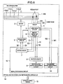
- FIG. 5 is a block diagram illustrating a multilayer optical disk recording and reproducing apparatus wich is useful for understanding the present invention.
- Reference numeral 41 denotes a first pickup
- 42 denotes a second pickup
- 51 denotes a first laser drive circuit
- 52 denotes a second laser drive circuit
- 61 denotes a first photodetector circuit
- 62 denotes a second photodetector circuit.
- the first pickup 41 includes the first laser drive circuit 51 and the first photodetector circuit 61
- the second pickup 42 includes the second laser drive circuit 52 and the second photodetector circuit 62, respectively. They are configured so as to be movable independently in the radius direction of the disk 1. Specifically, the focus control and tracking control of the first pickup 41 and the second pickup 42 are each controlled independently by the servo control signal C1 of the first photodetector circuit 61, the servo control signal C2 of the second photodetector circuit 62, and the output signals S1 and S2 of the servo circuit 7.
- the simultaneous recording operation can be performed on an arbitrary radius position of two adjacent layers (e.g., the L0 recording layer 110 and the L1 recording layer 111).
- independent pickups are arranged at positions opposing to each other at an angle of 180°; however, this arrangement is not limited thereto and, for example, independent pickups may be arranged at intervals of about 90°. Further, three independent pickups may be arranged at intervals of about 120°.
- FIG. 6 is a block diagram illustrating one embodiment of a multilayer optical disk recording and reproducing apparatus wich is useful for understanding this invention.
- the apparatus 14 according to the embodiment shown in FIG. 1 is configured to irradiate the first laser beam 121 and the second laser beam 122 alternately at the same time.
- the apparatus 14 shown in FIG. 6 is configured to perform a recording operation on two adjacent layers connected to each other at the same time.
- the first laser beam 121 sequentially records information data on a recording track of the L0 recording layer 110
- the second laser beam 122 records information data on a recording track of the L1 recording layer 111.
- each laser beam performs an interlayer jump as much as two recording layers and performs a focus adjustment.
- the first laser beam 121 records the information data on a recording track of the L2 recording layer 112
- the second laser beam 122 records the information data on a recording track of the L3 recording layer 113.
- the recording direction of the L1 recording layer 111 and of the L2 recording layer 112 are opposite as compared with the embodiment shown in FIG. 1 ; however, the recording/reproducing control is performed using the physical address, and therefore, there is no problem regarding operations.
- the first laser beam 121 records the information data on a recording track of the L2 recording layer 112
- the second laser beam 122 records the information data on a recording track of the L3 recording layer 113; further, each laser beam may record the information data on a recording track of the recording layer from an inner peripheral surface to an outer peripheral surface.
- a four-layer optical disk and two laser beams are used is described above; however, the arrangement is not limited thereto.
- a combination of a six-layer optical disk and two laser beams as well as of a six-layer optical disk and three laser beams may be used. Even if the number of layers and the number of laser beams further increase, the apparatus 14 according to the present invention can accept these combinations.
- three recording layers can record or reproduce the information data at the same time. Accordingly, the time required to be recorded or reproduced can be reduced to one third of the conventional time, and the speeding up can be further realized as compared with a case of using two laser beams.
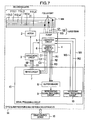
- FIG. 7 is a block diagram illustrating another embodiment of the multilayer optical disk recording and reproducing apparatus according to the present invention.
- the same parts as those of FIG. 1 are indicated by the same reference numerals as those of FIG. 1 .
- Reference numeral 114 denotes an L4 recording layer
- 115 denotes an L5 recording layer
- 123 denotes a third laser beam.
- the configuration of FIG. 7 is different from that of FIG. 1 in that a six-layer optical disk and three laser beams are used.
- the drive control device 15 when commanding a three-layer simultaneous recording mode, causes the recording signal processing circuit 10 to operate at a speed being three times as fast as the conventional speed as well as to output three recording signal data strings W1, W2 and W3 at the same time, and causes the pickup 4 to emit the first laser beam 121, the second laser beam 122, and the third laser beam 123, respectively.
- Each of the recording signal data strings W1 W2, and W3 at this time has the same data transmission speed as that at the time of the conventional single layer recording operation.
- the servo drive circuit 3 performs a focus control such that the first laser beam 121 focuses on the L0 recording layer 110, the second laser beam 122 focuses on the L2 recording layer 112, and the third laser beam 123 focuses on the L4 recording layer 114.
- the first laser beam 121 sequentially records the information data on a recording track of the L0 recording layer 110
- the second laser beam 122 records the information data on a recording track of the L2 recording layer 112
- the third laser beam 123 records the information data on a recording track of the L4 recording layer 114.
- the first laser beam 121 records the information data on a recording track of the L1 recording layer 111
- the second laser beam 122 records the information data on a recording track of the L3 recording layer 113
- the third laser beam 123 records the information data on a recording track of the L5 recording layer 115.
- the time required to be recorded can be reduced to one third of the conventional time.
- the recorded data can be reproduced in one third of the conventional time.
- the focus control and tracking control of the first laser beam 121, the second laser beam 122, and the third laser beam 123 are each controlled independently by the servo control signals C1, C2, and C3 of the photodetector circuit 6 as well as by the output signals S1, S2, and S3 of the servo circuit 7.
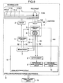
- FIG. 8 is a block diagram according to a second embodiment of the present invention.
- FIG. 8 illustrates an example where the first laser beam 121 is used only for the recording operation, the second laser beam 122 is used only for the reproducing operation and they are used for the recording and reproducing operations to and from the L0 recording layer 110.
- the recording operation can be performed using one laser beam in the same manner as in the conventional configuration.
- any one of the first laser beam 121 and the second laser beam 122 is operated, and the recording mode or the reproducing mode may be switched.
- the operation in the recording mode is performed using the recording signal data string W1 and reproducing signal data string R1 outputted from the recording signal processing circuit 13.
- both of the first laser beam 121 and the second laser beam 122 focus on the L0 recording layer 110.
- the recorded data is reproduced using the second laser beam 122.
- the recorded data can be continuously checked with the reproduced data (read after write process).
- the read after write process is performed such that one laser beam is switched from the recording mode to the reproducing mode immediately after the recording operation and the laser beam is moved, by performing a track-jump operation, up to a starting point of the data recorded immediately before.
- the present invention exerts the following effect as compared with the conventional method. That is, since the reproducing operation can be continuously performed using the second laser beam 122 immediately after the recording operation is performed using the first laser beam 121, the read after write process can be performed in half of the conventional time without performing a track-jump operation.
- any one of the first laser beam and the second laser beam may be operated.
- power consumption can be equal to that of the conventional apparatus.
- the dual-layer simultaneous recording method and the single layer recording method are described above; further, these methods can be mixedly used according to need of the high-speed recording operation.
- FIG. 9 illustrates one example of a recording area distribution at the time of recording a plurality of data files on the multilayer optical disk.
- Each numeral of FIG. 9 represents a recording order of recording files, alphabetical characters a, and b represent that the files are recorded at the same time, and an arrow represents a size of the recording file, respectively.
- a file 2 since being in the normal single layer recording mode, is recorded subsequent to a file 1 recording end part (1a) of the L0 recording layer 110 (2).
- a file 3 since being in the simultaneous recording mode, is recorded subsequent to the file 2 recording end part (2) of the L0 recording layer 110 and to the same physical address of the L2 recording layer 112 as that of the L0 recording layer 110.
- a jump operation of one recording layer is each performed at the time of finishing the recording operation of the L0 recording layer 110 and the L2 recording layer 112, and subsequently, the recording operation is performed on the L1 recording layer 111 and the L3 recording layer 113 (3a, 3b).
- a file 4 since being in the normal single layer recording mode, is recorded subsequent to a file 1 recording end part (1b of the L2 recording layer 112 (4).
- a file 5, since being in the simultaneous recording mode, is recorded subsequent to a file 3 recording end part (3a) of the L1 recording layer 111 and to a file 3 recording end part (3b) of the L3 recording layer 113 (5a, 5b).
- a file 6, since being in the normal single layer recording mode is recorded subsequent to a file 5 recording end part (5a) of the L1 recording layer 111 (6).
- control is performed so as to start the recording operation from the same physical address of each recording layer. This facilitates management of the physical addresses even if the single layer recording format mixedly exists.
- the file 2 shown in FIG. 9 can be here reproduced using a conventional Blu-ray disk reproducing apparatus.
- the L0 recording layer 110 is set so as to be selected to record information data desired to be reproduced using a conventional disk reproducing apparatus.
- a normal file data recording operation is described above; further, even if the recording data is image information, the present invention is applicable to the recording data.
- the image information is required to be transmitted with higher speed and in larger capacity.
- the recorder for recording the information is required to be high-quality and high-speed.
- an image compression rate is required to be reduced as much as possible so as to record vast information data on time.
- two recording layers can be recorded at the same time according to the present invention. Therefore, for a high-capacity data such as high-definition image information, the recording data is divided into halves by two layers, thereby performing the high-speed recording operation.
- the present invention exerts an effect that with regard to the reproducing operation, since vast information data can be reproduced on two layers at the same time, higher-quality image signals are obtained. Further, the present invention can be applied not only to a write once disk and a rewritable disk but also to a disk exclusive for reproduction such as a ROM.
- the reproducing operation is performed on the L0 recording layer 110 using the conventional disk reproducing apparatus, thereby reproducing an image equivalent to the standard image.
- FIG. 10 illustrates one example of the multilayer optical disk.
- FIG. 10 illustrates a multi-laser beam corresponding multilayer optical disk.
- the multilayer optical disk is configured such that the recording track guide groove and physical address are formed in the L0 recording layer 110, and the L1 to L5 recording layers each have only a recording film.
- the pickup emits two or more laser beams as described above.
- the pickup 4 focuses, for example, the first laser beam 121 on the L0 recording layer 110, and the servo drive circuit 3 performs a tracking control and recording address control.
- the pickup 4 focuses the second laser beam 122 on another recording layer, for example, on the L1 recording layer 111 and performs the recording and reproducing operations.
- the servo circuit 7 controls the servo drive circuit 3 to perform the tracking control of the second laser beam 122 while following that of the first laser beam 121.
- the recording track guide groove is not required and only the recording film may be formed. Since the management of bonding position accuracy of each recording layer is not required, disk costs can be largely reduced.
- FIG. 10 illustrates an example where the recording track guide groove and physical addresses are formed in the L0 recording layer 110.
- the recording track guide groove and physical addresses may be formed in any one of the other recording layers.
- FIG. 11 illustrates one example of another multilayer optical disk.
- the multilayer optical disk shown in FIG. 11 is configured such that the recording track guide groove and physical addresses are formed in the L0 recording layer 110, the L2 recording layer 112, and the L4 recording layer 114, and the L1 recording layer 111, the L3 recording layer 113, and the L5 recording layer 115 each have only the recording film.
- the tracking control of the first laser beam 121 is used for that of the second laser beam 122 at the same time. Therefore, if once the simultaneous recording operation is performed on the L0 recording layer 110 having the recording track guide groove and another recording layer, only the single layer recording operation can be performed next time and at subsequent times. This exerts the following effect as compared with the multilayer optical disk shown in FIG. 10 . That is, the multilayer optical disk shown in FIG. 11 alternately has the recording layers with the recording track guide groove, and therefore, the dual-layer simultaneous recording operation can be always performed.
- the present invention is not limited to the Blu-ray disk device, and applicable also to DVD devices and CD devices.
Landscapes
- Physics & Mathematics (AREA)
- Optics & Photonics (AREA)
- Optical Recording Or Reproduction (AREA)
- Optical Head (AREA)
- Optical Record Carriers And Manufacture Thereof (AREA)
- Signal Processing For Digital Recording And Reproducing (AREA)
Abstract
Description
- The present invention relates to an optical disk recording apparatus and optical disk reproducing apparatus and, more particularly, to a multilayer optical disk recording apparatus and multilayer optical disk reproducing apparatus capable of high-speed recording of a multilayer optical disk.
- For a technology of the speeding up related to the present invention, for example, disclosed in
JP-A-2006-164374 JP-A-2006-164374 - In the market for optical disk media represented by DVD, increase in density is in progress to adapt to a large capacity of recording information. Blu-ray Disk and HD-DVD, for which blue laser is used as a light source, are recently commercialized. And a recording capacity of 25 GB on one side is realized using Blu-ray disk technology. Further, a recording operation of a multilayer medium is enabled due to the increase in output power of blue laser. For example, information data of 50 GB can be recorded on one side using a dual-layer disk of Blu-ray Disk system. Development to this large recording capacity is predicted to be promoted in the future with a central focus on the development of a multi-layering technology.
- As described above, the storage capacity of one optical disk largely increases with the adoption of blue laser. Accordingly, the processing time required to be recorded and reproduced also increases as much as an increased storage capacity. At the present, the high-speed recording and reproducing technological development such as sixfold speed is being promoted along with a larger capacity of the optical disk. A current system configuration is considered to have a limit of about twelvefold speed from the limitations of the disk rotation number.
- For this high-speed technology, disclosed is a multilayer simultaneous recording technology in
JP-A-2006-164374 - In view of the foregoing, it is a preferred aim of the present invention to provide a multilayer optical disk recording apparatus and multilayer optical disk reproducing apparatus which may perform a stable high-speed recording operation under a simple control.
JP-A-2006-268952 JP-A-2006-268952 - According to a first aspect of the present invention there is provided a multilayer optical disk recording apparatus for recording information on a multilayer optical disk having a plurality of recording layers in a thickness direction, comprising an optical pickup that emits N (N represents an integer of two or more) laser beams of the same wavelength, the apparatus being adapted to cause the optical pickup: to emit the N laser beams at the same time;
wherein: - the apparatus is further adapted to cause the optical pickup:
- to focus the N laser beams on a first recording layer group said first group being composed of N alternating layers among the plurality of layers, and
- to perform a recording operation on the recording layers at the same time; and
- when changing the recording layers
- to focus the N laser beams on a second recording layer group composed of the N recording layers adjacent to the respective recording layers of the first group, and
- to perform a recording operation on the recording layers of the second group at the same time.
- According to a second aspect of the invention there is provided a multilayer optical disk reproducing apparatus for reproducing information recorded on a multilayer optical disk having a plurality of recording layers in a thickness direction, comprising an optical pickup that emits N (N represents an integer of two or more) laser beams of the same wavelength, the apparatus being adopted to cause the optical pickup: to emit the N laser beams at the same time;
wherein: - the apparatus is further adapted to cause the optical pickup:
- to focus the N laser beams on a first recording layer group, said first group being composed of N alternative layers among the plurality of layers, and
- to perform a reproducing operation on recording layers of the first group; and
- when changing the recording layers, to focus the N laser beams on a second recording layer group composed of the N recording layers adjacent to the respective recording layers of the first group, and
- to perform a reproducing operation on the recording layers of the second group at the same time.
- With the present invention it is possible for a multilayer optical disk recording or reproducing apparatus which can perform recording or reproducing with the recording or reproducing speed being stably made high under a simple control.
- In the drawings:
-
FIG. 1 is a block diagram of a multilayer optical disk recording and reproducing apparatus according to the present invention; -
FIG. 2 is a schematic diagram of a position relation between a laser beam and a recording track according to the present invention; -
FIG. 3 illustrates one example of a physical address of a multilayer optical disk according to the present invention; -
FIG. 4 is a block diagram of a multilayer optical disk recording and reproducing apparatus which is useful for understanding the present invention; -
FIG. 5 is a block diagram of a multilayer optical disk recording and reproducing apparatus which is useful in understanding the present invention; -
FIG. 6 is a block diagram of a multilayer optical disk recording and reproducing apparatus which is useful in understanding the present invention; -
FIG. 7 is a block diagram of a multilayer optical disk recording and reproducing apparatus according to the present invention; -
FIG. 8 is a block diagram of a multilayer optical disk recording and reproducing apparatus according to the present invention; -
FIG. 9 illustrates one example of a plurality of file recording location; -
FIG. 10 illustrates one example of a configuration of a multilayer optical disk; and -
FIG. 11 illustrates one example of a configuration of a multilayer optical disk. - Hereinafter, preferred embodiments of the present invention will be described with reference to the accompanying drawings.
-
FIG. 1 is a block diagram illustrating one embodiment of a multilayer optical disk recording and reproducing apparatus according to the present invention.Reference numeral 1 denotes a disk, 2 denotes a motor, 3 denotes a servo drive circuit, 4 denotes a pickup, 5 denotes a laser drive circuit, 6 denotes a photodetector circuit, 7 denotes a servo circuit, 8 denotes a buffer memory, 9 denotes a reproducing signal processing circuit, 10 denotes a recording signal processing circuit, 110 denotes an L0 recording layer, 111 denotes an L1 recording layer, 112 denotes an L2 recording layer, 113 denotes an L3 recording layer, 121 denotes a first laser beam, 122 denotes a second laser beam, 13 denotes a signal processing circuit, 14 denotes an optical disk recording and reproducing apparatus, and 15 denotes a drive control device. - According to the present embodiment of
FIG. 1 , a 4-layer disk is used as thedisk 1, and thefirst laser beam 121 and thesecond laser beam 122 are emitted so as to correspond to a dual-layer simultaneous recording operation. - At first, basic operations of the optical disk recording and reproducing
apparatus 14 will be described. Only thefirst laser beam 121 is normally irradiated from thepickup 4. When a BD-R disk 1 as a one-time writing disk in a Blu-Ray system is inserted into the optical disk recording and reproducingapparatus 14, thedisk 1 is rotated by themotor 2, theservo circuit 7 and theservo drive circuit 3, and thefirst laser beam 121 that is controlled to a power value for reproduction is irradiated on a recording surface of thedisk 1 from thepickup 4. Thephotodetector circuit 6 detects the intensity of light reflected by thedisk 1 of thefirst laser beam 121 to thereby obtain reproducing digital signal trains.
Next, the reproducing digital signal trains are decoded using thebuffer memory 8 and the reproducingsignal processing circuit 9, and information of the control signals recorded on thedisk 1 is read out, thereby discriminating a disk medium. When thedisk 1 here inserted is determined to be a BD-R, the optical disk recording and reproducingapparatus 14 is in an operation standby state. Thereafter, the optical disk recording and reproducingapparatus 14 is controlled in a recording or reproducing state of data, for example, based on instructions of thedrive control device 15 configured by a host computer. - During the recording operation, under the control of the
servo circuit 7, theservo drive circuit 3 rotates thedisk 1 at a predetermined speed, and at the same time, performs processings such as a focus control, tracking control, and optimum recording power control of thefirst laser beam 121. Next, digital data strings W1 outputted from the recordingsignal processing circuit 10 within thesignal processing circuit 13 are transmitted to thelaser drive circuit 5. Further, thelaser drive circuit 5 sets a power value of a recording data signal to a predetermined value, and sequentially records information data on a track of thedisk 1. - Also during the reproducing operation, in the same manner, the
servo drive circuit 3 rotates thedisk 1 at a predetermined speed, and at the same time, performs processings such as a focus control and tracking control of thefirst laser beam 121, whereby recorded reproduction digital data strings R1 are sequentially reproduced. - Speeding-up of the operations of the optical disk recording and reproducing
apparatus 14 having the above-described configuration will be described. - To realize a reproduction speed of sixfold speed at the outer peripheral surface, for example, by a constant angular velocity (CAV) system, the number of rotations of the
motor 2 is controlled to 4860 rotations per minute using theservo drive circuit 3. Next, thephotodetector circuit 6 detects reflected light of thefirst laser beam 121 outputted from thepickup 4. Further, thephotodetector circuit 6 scans one recording track that is spirally formed from an inner periphery to outer periphery of thedisk 1, and obtains the reproduction digital data strings R1. At this time, the reproduction speed at the outer peripheral portion of thedisk 1 is the fastest sixfold speed, and the signal frequency to be reproduced is a repeating signal with 2T (T is a bit period) of 99 MHz. Meanwhile, the reproduction speed at the inner peripheral portion of thedisk 1, since the number of rotations of themotor 2 is 4860 rotations per minute, is a two and half-fold speed. - In the CAV system, the number of a maximum double speed is thus determined by the number of rotations of the
disk 1. For example, when the allowable number of rotations of themotor 2 is determined to be 10000 rotations or less per minute (9720 rotations per minute),the number of the maximum double speed is fivefold speed at the inner peripheral surface, and is twelvefold speed at the outer peripheral surface, respectively. - Next, an operation of the
signal processing circuit 13 will be described. At first, the data is reproduced by the operations of a PLL circuit that detects a transmission clock from among the reproduction digital signal trains R1 as well as by those of a partial response reproducing circuit that adapts a transmission system to a partial response. Thereafter, the reproduced data is once stored in thebuffer memory 8. The data stored in thebuffer memory 8 is sequentially read out by the reproducingsignal processing circuit 9, and the information data recorded on thedisk 1 is reproduced using circuit operations (not shown) of a synchronization signal detection circuit, a demodulation circuit, and an error detecting and correcting circuit. The speed equivalent to twelvefold speed can be realized by the adoption of a micromachining process in relation to the operation speed of the above-described circuits. - In the general optical disk recording and reproducing
apparatus 14, a number of signals such as RF signals or servo signals as signals outputted from thephotodetector circuit 6 within thepickup 4 are here required to be transmitted to the circuit board. Further, due to the signal transmission between a moving part and a fixed part, thepickup 4 and the circuit board are connected to each other, in many cases, by a conductor wiring printed on a flexible sheet. The wiring using this flexible sheet is suitable for the above-described connection between the moving part and the fixed part; however, has a fault that when a wiring interval is narrowed, capacitance between wirings increases, and further, this capacitance between wirings is resonated with the inductance of transmission line to thereby narrow the transmission band width. The transmission band width is on the order of 150 MHz depending on the design (wiring length, wiring width, and wiring interval) of the flexible sheet. This transmission band width is equal to the frequency spectrum distribution band width in the sixfold speed using the above-described Blu-Ray system, and therefore, the transfer speed of an eightfold speed or more is hard to be realized using a conventional apparatus configuration. Accordingly, based on frequency characteristics of this transmission circuit, the sixfold speed is the reproduction speed that can be realized with stable operations in a conventional system configuration. - As compared with one beam system described above, the following method as shown in
FIG. 1 is used in the present invention. That is, during the recording and reproducing operations, thefirst laser beam 121 and thesecond laser beam 122 are emitted, and both of the operations are performed on two recording layers at the same time, thereby realizing a speeding up being twice as fast as the conventional speed. -
FIG. 2 illustrates an example of an arrangement of two laser beams according to the present invention. InFIG. 2 , thefirst laser beam 121 and thesecond laser beam 122 are formed in line in a recording track direction of thedisk 1. - The
drive control device 15 shown inFIG. 1 , when commanding a dual-layer simultaneous recording mode, causes the recordingsignal processing circuit 10 to operate at a speed being twice as fast as the conventional speed as well as to output two recording signal data strings W1 and W2 at the same time, and causes theoptical pickup 4 to emit thefirst laser beam 121 and thesecond laser beam 122, respectively. Each of the recording signal data strings W1 and W2 at this time has the same data transmission speed as that at the time of a conventional single layer recording operation. In the present embodiment, theservo drive circuit 3 performs a focus control such that thefirst laser beam 121 focuses on theL0 recording layer 110 and thesecond laser beam 122 focuses on theL2 recording layer 112. - Next, from the inner peripheral surface to the outer peripheral surface of the
disk 1, thefirst laser beam 121 sequentially records information data on a recording track of theL0 recording layer 110 and thesecond laser beam 122 records information data on a recording track of theL2 recording layer 112. When the recording operation is finished up to the outermost peripheral surface of thedisk 1, each laser beam performs an interlayer jump as much as one recording layer and performs a focus adjustment. From the outer peripheral surface to the inner peripheral surface, at this time, thefirst laser beam 121 records the information data on the recording track of theL1 recording layer 111 and thesecond laser beam 122 records the information data on the recording track of theL3 recording layer 113. -
FIG. 3 illustrates one example of a physical address of the multilayer optical disk used in the present embodiment. - In
FIG. 3 , thedisk 1 has 6 recording layers, and the physical address is configured so as to increase in the order corresponding to the L0 recording layer inner periphery, the L0 recording layer outer periphery, the L1 recording layer outer periphery, the L1 recording layer inner periphery, the L2 recording layer inner periphery, the L2 recording layer outer periphery, the L3 recording layer outer periphery, the L3 recording layer inner periphery, the L4 recording layer inner periphery, the L4 recording layer outer periphery, the L5 recording layer outer periphery, and the L5 recording layer inner periphery. The layer number is imparted to a high-order position of each address, and further, the same physical address is imparted to the same radius position of theL0 recording layer 110, theL2 recording layer 112, and theL4 recording layer 114 as well as that of theL1 recording layer 111, theL3 recording layer 113, and theL5 recording layer 115. As one example, the layer number is here imparted to the high-order position of each address; however, the present embodiment is not limited thereto. - The present invention exerts the following effects. At first, when the information data is recorded on a multilayer disk to which the physical address is thus imparted, the dual-layer simultaneous recording operation is performed alternately in the same radius position as described above. Thereby, since only the layer number is different from each other and the recording operation can be performed on each recording layer by the same physical address, this facilitates management of the physical address. Secondly, when the recording layer is moved at the time when a recordable region of each recording layer disappears, the interlayer jump is required to be performed as much as two recording layers in the case of performing the simultaneous recording operation in adjacent recording layers. However, in the method for alternately performing the simultaneous recording operation according to the present invention shown in
FIG. 1 , since each laser beam may perform the interlayer jump as much as one recording layer, a stable and rapid movement can be performed. - In order that the recording physical addresses between both the recording layers may be here allowed to correspond to each other in the case of using an arrangement of the laser beam shown in
FIG. 2 , the data transmission to thesecond laser beam 122 may be delayed as compared with that to thefirst laser beam 121 as much as a distance between two laser beams. In the same manner, also during the reproducing operation, in order to obtain the reproduction data with the same physical address, the data transmission to thesecond laser beam 122 may be delayed as compared with that to thefirst laser beam 121. - During the reproducing operation in
FIG. 1 , thefirst laser beam 121 and thesecond laser beam 122 are each set to reproducing laser power. By using the same servo process as that during the recording operation, thefirst laser beam 121 irradiates theL0 recording layer 110, and meanwhile, thesecond laser beam 122 irradiates theL2 recording layer 112 for the simultaneous reproduction, thereby obtaining the reproduction signal trains R1 and R2. Next, when the reproducing operation is finished up to the outermost peripheral surface, each laser beam performs the interlayer jump as much as one recording layer and performs the focus adjustment. Thereafter, at this time, thefirst laser beam 121 irradiates a recording track of theL1 recording layer 111, and meanwhile, thesecond laser beam 122 irradiates a recording track of theL3 recording layer 113 for the simultaneous reproduction from the outer peripheral surface to the inner peripheral surface. - As described above, in the dual-layer simultaneous recording operation according to the present invention, since a series of information data blocks is divided into two data strings W1 and W2 to be recorded, two data strings R1 and R2 are reproduced at the same time to be sequentially stored in the
buffer memory 8 in parallel during the reproducing operation. During the reading operation, the data address number is detected based on data ID codes of the data to be rearranged to the original series data strings based on these signals. - After the determination of the data order, the
signal processing circuit 13 performs a double speed operation. Specifically, after reading out thebuffer memory 8, thesignal processing circuit 13 causes a synchronization signal detection circuit, a demodulator circuit, and an error detecting and correcting circuit to operate, for example, at the twelvefold speed mode (basic transmission clock frequency: 792 MHz). By using the above-described configuration, an analog signal operating area may be a transmission band width equivalent to the sixfold speed, and the data reproduction of the twelvefold speed can be performed also using the signal transmission by the conventionally-used flexible sheet. Further, the operation clock frequencies of thesignal processing circuit 13 can be reduced by performing a part of the processings in parallel. The reproduction of the recorded data can be reduced to half of a conventional time through this dual-layer simultaneous reproducing operation. - In the multilayer disk here used in the present invention, an eccentricity amount is expected to be different from each other at each recording layer in the process of manufacture. However, the focus control and tracking control of the
first laser beam 121 and thesecond laser beam 122 are each controlled independently by the servo control signals C1 and C2 of thephotodetector circuit 6 as well as by the output signals S1 and S2 of theservo circuit 7. Therefore, the focus control and tracking control can be easily adjusted using a conventional method and are not required to be intricately adjusted. - When a data recording error occurs during the recording operation, the recording retry process is performed in the same manner as in the conventional apparatus. When the error still cannot be corrected, the defect management is performed. At this time, both of the recording retry process and the defect management are performed to adjust only the relevant recording layer, and the other laser beam is set to a reproduction mode such that the recording operation is not performed. In this connection, the same information data as the change information is recorded in the disk management area formed in the recording layer during the simultaneous recording operation.
- In
FIG. 2 , an example where thefirst laser beam 121 is arranged on theL0 recording layer 110, and thesecond laser beam 122 is arranged on theL2 recording layer 112 is described. Further, when managing even the recording timing, thefirst laser beam 121 may be arranged on theL2 recording layer 112, and thesecond laser beam 122 may be arranged on theL0 recording layer 110. - The physical address shown in
FIG. 3 is started as a starting point from the inner peripheral portion of the L0 recording layer; however, there is no problem even if the physical address is started as a starting point from the outer peripheral portion of the L0 recording layer. The physical address at this time is configured so as to increase in the order corresponding to the L0 recording layer outer periphery, the L0 recording layer inner periphery, the L1 recording layer inner periphery, the L1 recording layer outer periphery, the L2 recording layer outer periphery, the L2 recording layer inner periphery, the L3 recording layer inner periphery, the L3 recording layer outer periphery, the L4 recording layer outer periphery, the L4 recording layer inner periphery, the L5 recording layer inner periphery, and the L5 recording layer outer periphery. InFIG. 3 , a deepest layer of thedisk 1 is defined as the L0 recording layer; however, a surface layer of thedisk 1 may be defined as the L0 recording layer and the deepest layer may be defined as the L5 recording layer. - When the information data is thus recorded and reproduced using two layers at the same time, the time required to be recorded or reproduced can be reduced to half of the conventional time. Accordingly, the recording and reproducing operations of the twelvefold speed can be performed also by using the above-described flexible sheet.
- An example where used is one
pickup 4 that emits two laser beams arranged in line is described above. -
FIG. 4 illustrates an example of arrangement of two pickups. InFIG. 4 , twopickups -
FIG. 5 is a block diagram illustrating a multilayer optical disk recording and reproducing apparatus wich is useful for understanding the present invention. InFIG. 5 , the same parts as those ofFIG. 1 are indicated by the same reference numerals as those ofFIG. 1 .Reference numeral 41 denotes a first pickup, 42 denotes a second pickup, 51 denotes a first laser drive circuit, 52 denotes a second laser drive circuit, 61 denotes a first photodetector circuit, and 62 denotes a second photodetector circuit. - The
first pickup 41 includes the firstlaser drive circuit 51 and thefirst photodetector circuit 61, and thesecond pickup 42 includes the secondlaser drive circuit 52 and thesecond photodetector circuit 62, respectively. They are configured so as to be movable independently in the radius direction of thedisk 1. Specifically, the focus control and tracking control of thefirst pickup 41 and thesecond pickup 42 are each controlled independently by the servo control signal C1 of thefirst photodetector circuit 61, the servo control signal C2 of thesecond photodetector circuit 62, and the output signals S1 and S2 of theservo circuit 7. - Since the two
independent pickups FIG. 1 . Therefore, as shown inFIG. 5 , the simultaneous recording operation can be performed on an arbitrary radius position of two adjacent layers (e.g., theL0 recording layer 110 and the L1 recording layer 111). - An example where the two independent pickups are arranged at positions opposing to each other at an angle of 180° is described above; however, this arrangement is not limited thereto and, for example, independent pickups may be arranged at intervals of about 90°. Further, three independent pickups may be arranged at intervals of about 120°.
-
FIG. 6 is a block diagram illustrating one embodiment of a multilayer optical disk recording and reproducing apparatus wich is useful for understanding this invention. - The
apparatus 14 according to the embodiment shown inFIG. 1 is configured to irradiate thefirst laser beam 121 and thesecond laser beam 122 alternately at the same time. Theapparatus 14 shown inFIG. 6 is configured to perform a recording operation on two adjacent layers connected to each other at the same time. InFIG. 6 , from an inner peripheral surface to an outer peripheral surface of thedisk 1, thefirst laser beam 121 sequentially records information data on a recording track of theL0 recording layer 110, and meanwhile, thesecond laser beam 122 records information data on a recording track of theL1 recording layer 111. When the recording operation is finished up to the outermost peripheral surface of thedisk 1, each laser beam performs an interlayer jump as much as two recording layers and performs a focus adjustment. Then, from an outer peripheral surface to an inner peripheral surface, at this time, thefirst laser beam 121 records the information data on a recording track of theL2 recording layer 112, and thesecond laser beam 122 records the information data on a recording track of theL3 recording layer 113. - The recording direction of the
L1 recording layer 111 and of theL2 recording layer 112 are opposite as compared with the embodiment shown inFIG. 1 ; however, the recording/reproducing control is performed using the physical address, and therefore, there is no problem regarding operations. - In the above description, from an outer peripheral surface to an inner peripheral surface, the
first laser beam 121 records the information data on a recording track of theL2 recording layer 112, and thesecond laser beam 122 records the information data on a recording track of theL3 recording layer 113; further, each laser beam may record the information data on a recording track of the recording layer from an inner peripheral surface to an outer peripheral surface. - An example where a four-layer optical disk and two laser beams are used is described above; however, the arrangement is not limited thereto. A combination of a six-layer optical disk and two laser beams as well as of a six-layer optical disk and three laser beams may be used. Even if the number of layers and the number of laser beams further increase, the
apparatus 14 according to the present invention can accept these combinations. When using the three laser beams, three recording layers can record or reproduce the information data at the same time. Accordingly, the time required to be recorded or reproduced can be reduced to one third of the conventional time, and the speeding up can be further realized as compared with a case of using two laser beams. -
FIG. 7 is a block diagram illustrating another embodiment of the multilayer optical disk recording and reproducing apparatus according to the present invention. InFIG. 7 , the same parts as those ofFIG. 1 are indicated by the same reference numerals as those ofFIG. 1 .Reference numeral 114 denotes an L4 recording layer, 115 denotes an L5 recording layer, and 123 denotes a third laser beam. The configuration ofFIG. 7 is different from that ofFIG. 1 in that a six-layer optical disk and three laser beams are used. - In
FIG. 7 , when commanding a three-layer simultaneous recording mode, thedrive control device 15 causes the recordingsignal processing circuit 10 to operate at a speed being three times as fast as the conventional speed as well as to output three recording signal data strings W1, W2 and W3 at the same time, and causes thepickup 4 to emit thefirst laser beam 121, thesecond laser beam 122, and thethird laser beam 123, respectively. Each of the recording signal data strings W1 W2, and W3 at this time has the same data transmission speed as that at the time of the conventional single layer recording operation. In the present embodiment, theservo drive circuit 3 performs a focus control such that thefirst laser beam 121 focuses on theL0 recording layer 110, thesecond laser beam 122 focuses on theL2 recording layer 112, and thethird laser beam 123 focuses on theL4 recording layer 114. - Next, from the inner peripheral surface to the outer peripheral surface of the
disk 1, thefirst laser beam 121 sequentially records the information data on a recording track of theL0 recording layer 110, thesecond laser beam 122 records the information data on a recording track of theL2 recording layer 112, and thethird laser beam 123 records the information data on a recording track of theL4 recording layer 114. When the recording operation is finished up to the outermost peripheral surface, each laser beam performs an interlayer jump as much as one recording layer and performs a focus adjustment. Then, from the outer peripheral surface to the inner peripheral surface, at this time, thefirst laser beam 121 records the information data on a recording track of theL1 recording layer 111, thesecond laser beam 122 records the information data on a recording track of theL3 recording layer 113, and thethird laser beam 123 records the information data on a recording track of theL5 recording layer 115. - When the information data is thus recorded using three recording layers at the same time, the time required to be recorded can be reduced to one third of the conventional time.
- In the same manner, when the reproducing operation is performed on three recording layers at the same time, the recorded data can be reproduced in one third of the conventional time.
- Herein, the focus control and tracking control of the
first laser beam 121, thesecond laser beam 122, and thethird laser beam 123 are each controlled independently by the servo control signals C1, C2, and C3 of thephotodetector circuit 6 as well as by the output signals S1, S2, and S3 of theservo circuit 7. - An example where the recording operation is performed alternately on three recording layers at the same time is described above; further, the simultaneous recording and reproducing operation may be performed on three recording layers connected to each other as described above. When the disk rotation control is performed by the above-described CAV system, a high-speed access can be performed to recording areas in each layer and between layers.
-
FIG. 8 is a block diagram according to a second embodiment of the present invention. - The optical disk recording and reproducing
apparatus 14 shown inFIG. 8 is configured by the same parts as those ofFIG. 1 . Further,FIG. 8 illustrates an example where thefirst laser beam 121 is used only for the recording operation, thesecond laser beam 122 is used only for the reproducing operation and they are used for the recording and reproducing operations to and from theL0 recording layer 110. - In the case of performing the single layer recording operation, the recording operation can be performed using one laser beam in the same manner as in the conventional configuration. In
FIG. 8 , any one of thefirst laser beam 121 and thesecond laser beam 122 is operated, and the recording mode or the reproducing mode may be switched. When using, for example, thefirst laser beam 121, the operation in the recording mode is performed using the recording signal data string W1 and reproducing signal data string R1 outputted from the recordingsignal processing circuit 13. - As compared with the above-described conventional method, according to the second embodiment of the present invention, both of the
first laser beam 121 and thesecond laser beam 122 focus on theL0 recording layer 110. By this configuration, immediately after the recording operation is performed on theL0 recording layer 110 using thefirst laser beam 121, the recorded data is reproduced using thesecond laser beam 122. Thereby, the recorded data can be continuously checked with the reproduced data (read after write process). In the above-described conventional method, the read after write process is performed such that one laser beam is switched from the recording mode to the reproducing mode immediately after the recording operation and the laser beam is moved, by performing a track-jump operation, up to a starting point of the data recorded immediately before. As a result, the present invention exerts the following effect as compared with the conventional method. That is, since the reproducing operation can be continuously performed using thesecond laser beam 122 immediately after the recording operation is performed using thefirst laser beam 121, the read after write process can be performed in half of the conventional time without performing a track-jump operation. - When the data recorded on the single recording layer is reproduced in the present invention, any one of the first laser beam and the second laser beam may be operated. In this case, since non used circuit portion within the
signal processing circuit 13 can be turned off, power consumption can be equal to that of the conventional apparatus. - The dual-layer simultaneous recording method and the single layer recording method are described above; further, these methods can be mixedly used according to need of the high-speed recording operation.
-
FIG. 9 illustrates one example of a recording area distribution at the time of recording a plurality of data files on the multilayer optical disk. Each numeral ofFIG. 9 represents a recording order of recording files, alphabetical characters a, and b represent that the files are recorded at the same time, and an arrow represents a size of the recording file, respectively. - A
file 1, since being in simultaneous recording mode, is recorded on theL0 recording layer 110 and the L2 recording layer 112 (1a, 1b). Next, afile 2, since being in the normal single layer recording mode, is recorded subsequent to afile 1 recording end part (1a) of the L0 recording layer 110 (2). Afile 3, since being in the simultaneous recording mode, is recorded subsequent to thefile 2 recording end part (2) of theL0 recording layer 110 and to the same physical address of theL2 recording layer 112 as that of theL0 recording layer 110. In this case, since a size of thefile 3 is large, a jump operation of one recording layer is each performed at the time of finishing the recording operation of theL0 recording layer 110 and theL2 recording layer 112, and subsequently, the recording operation is performed on theL1 recording layer 111 and the L3 recording layer 113 (3a, 3b). Next, afile 4, since being in the normal single layer recording mode, is recorded subsequent to afile 1 recording end part (1b of the L2 recording layer 112 (4). Afile 5, since being in the simultaneous recording mode, is recorded subsequent to afile 3 recording end part (3a) of theL1 recording layer 111 and to afile 3 recording end part (3b) of the L3 recording layer 113 (5a, 5b). Finally, afile 6, since being in the normal single layer recording mode, is recorded subsequent to afile 5 recording end part (5a) of the L1 recording layer 111 (6). - In the case of performing the dual-layer simultaneous recording operation as described above, the control is performed so as to start the recording operation from the same physical address of each recording layer. This facilitates management of the physical addresses even if the single layer recording format mixedly exists.
- Since the deepest
L0 recording layer 110 has the same depth as that of existing BD-R, thefile 2 shown inFIG. 9 can be here reproduced using a conventional Blu-ray disk reproducing apparatus. For this purpose, in the multilayer optical disk recording and reproducing apparatus according to the present invention, theL0 recording layer 110 is set so as to be selected to record information data desired to be reproduced using a conventional disk reproducing apparatus. - A normal file data recording operation is described above; further, even if the recording data is image information, the present invention is applicable to the recording data. As high-definition broadcast becomes more widely used, the image information is required to be transmitted with higher speed and in larger capacity. Also, the recorder for recording the information is required to be high-quality and high-speed. For this purpose, an image compression rate is required to be reduced as much as possible so as to record vast information data on time. For the above-described request, two recording layers can be recorded at the same time according to the present invention. Therefore, for a high-capacity data such as high-definition image information, the recording data is divided into halves by two layers, thereby performing the high-speed recording operation. The present invention exerts an effect that with regard to the reproducing operation, since vast information data can be reproduced on two layers at the same time, higher-quality image signals are obtained. Further, the present invention can be applied not only to a write once disk and a rewritable disk but also to a disk exclusive for reproduction such as a ROM.
- Further, as described above, when the simultaneous recording operation is performed on the deepest
L0 recording layer 110 and theL2 recording layer 112, the reproducing operation is performed on theL0 recording layer 110 using the conventional disk reproducing apparatus, thereby reproducing an image equivalent to the standard image. -
FIG. 10 illustrates one example of the multilayer optical disk.FIG. 10 illustrates a multi-laser beam corresponding multilayer optical disk. The multilayer optical disk is configured such that the recording track guide groove and physical address are formed in theL0 recording layer 110, and the L1 to L5 recording layers each have only a recording film. - The pickup emits two or more laser beams as described above. Thereby, the
pickup 4 focuses, for example, thefirst laser beam 121 on theL0 recording layer 110, and theservo drive circuit 3 performs a tracking control and recording address control. Further, thepickup 4 focuses thesecond laser beam 122 on another recording layer, for example, on theL1 recording layer 111 and performs the recording and reproducing operations. At this time, theservo circuit 7 controls theservo drive circuit 3 to perform the tracking control of thesecond laser beam 122 while following that of thefirst laser beam 121. - According to the above-described configuration, in each of the L1 to L5 recording layers, the recording track guide groove is not required and only the recording film may be formed. Since the management of bonding position accuracy of each recording layer is not required, disk costs can be largely reduced.
-
FIG. 10 illustrates an example where the recording track guide groove and physical addresses are formed in theL0 recording layer 110. In addition to theL5 recording layer 115 near a surface of thedisk 1, the recording track guide groove and physical addresses may be formed in any one of the other recording layers. -
FIG. 11 illustrates one example of another multilayer optical disk. The multilayer optical disk shown inFIG. 11 is configured such that the recording track guide groove and physical addresses are formed in theL0 recording layer 110, theL2 recording layer 112, and theL4 recording layer 114, and theL1 recording layer 111, theL3 recording layer 113, and theL5 recording layer 115 each have only the recording film. - In the multilayer optical disk shown in
FIG. 10 , the tracking control of thefirst laser beam 121 is used for that of thesecond laser beam 122 at the same time. Therefore, if once the simultaneous recording operation is performed on theL0 recording layer 110 having the recording track guide groove and another recording layer, only the single layer recording operation can be performed next time and at subsequent times. This exerts the following effect as compared with the multilayer optical disk shown inFIG. 10 . That is, the multilayer optical disk shown inFIG. 11 alternately has the recording layers with the recording track guide groove, and therefore, the dual-layer simultaneous recording operation can be always performed. - Preferred embodiments of the multilayer optical disk recording and reproducing apparatus according to the present invention are described above. However, the present invention is not limited to the above embodiments and combinations of the above embodiments, various modifications and enhancements may be made without departing from the scope of the invention as defined in the appended claims.
- Details of the present invention are described using the Blu-ray disk device as an example. However, the present invention is not limited to the Blu-ray disk device, and applicable also to DVD devices and CD devices.
Claims (11)
- A multilayer optical disk recording apparatus (14) for recording information on a multilayer optical disk (1) having a plurality of recording layers (110, 111, 112, 113) in a thickness direction, comprising an optical pickup (4) that emits N (N represents an integer of two or more) laser beams of the same wavelength, the apparatus being adapted to cause the optical pickup (4): to emit the N laser beams at the same time;
characterised in that;
the apparatus is further adapted to cause the optical pickup (4):to focus the N laser beams on a first recording layer group said first group being composed of N alternating layers among the plurality of layers, andto perform a recording operation on the recording layers (110, 111, 112, 113) at the same time; andwhen changing the recording layers (110, 111, 112, 113),to focus the N laser beams on a second recording layer group composed of the N recording layers adjacent to the respective recording layers of the first group, andto perform a recording operation on the recording layers of the second group at the same time. - The multilayer optical disk recording apparatus (14) according to claim 1, wherein:the optical pickup (4) can irradiate the N laser beams in line in a track direction of the multilayer optical disk (1).
- The multilayer optical disk recording apparatus (14) according to claim 1, wherein:the apparatus is adapted to detect errors in the recorded data on any one of recording layers by a read after write process, to perform defect management of the recorded data, and when an error is detected and defect management is performed to record change information data on a disk management area of the recording layer and a disk management area of the other recording layers during a simultaneous recording operation.
- The multilayer optical disk recording apparatus (14) according to claim 1, wherein:the apparatus is adapted, when performing a recording operation on only one recording layer, to record data on the recording layer using an upstream laser beam with regard to a disk rotation direction, to set a downstream laser beam to reproducing power, to focus the downstream laser beam on the same recording layer as that of the upstream laser beam, and to reproduce the data recorded by the upstream laser beam to detect an error of the recorded data.
- The multilayer optical disk recording apparatus (14) according to claim 1, wherein:The apparatus is adapted, when performing a recording operation on only one recording layer (110, 111, 112, 113), to record the data on the deepest recording layer of the multilayer optical disk (1).
- The multilayer optical disk recording apparatus (14) according to claim 1, further comprising a servo drive circuit (3) and a servo circuit (7) that control tracking and focusing for the N laser beams on N recording layers, wherein:the servo drive circuit (3) and the servo circuit (7) being arranged to perform a focusing operating and a tracking operation of each of the N laser beams on N recording layers independently.
- The multilayer optical disk recording apparatus (14) according to claim 1, further comprising a recording signal processing circuit (10) arranged to generate a N recording digital signal trains and a laser drive circuit (5) arranged to emit the N laser beams, wherein:the apparatus is arranged to cause the recording signal processing circuit (10):to operate at a operating speed being N-fold as fast as a predetermined data transmission speed andto transmit the N recording digital signal trains to the laser drive circuit (5) with the predetermined data transmission rate simultaneously; andthe apparatus is arranged to cause the laser drive circuit (5);to perform a emitting operation of the N laser beams andto perform a recording operation on N recording layers simultaneously.
- A multilayer optical disk reproducing apparatus (14) for reproducing information recorded on a multilayer optical disk (1) having a plurality of recording layers (110, 111, 112, 113) in a thickness direction, comprising an optical pickup (4) that emits N (N represents an integer of two or more) laser beams of the same wavelength, the apparatus being adopted to cause the optical pickup (4): to emit the N laser beams at the same time;
characterised in that:the apparatus is further adapted to cause the optical pickup (9):to focus the N laser beams on a first recording layer group, said first group being composed of N alternative layers among the plurality of layers, andto perform a reproducing operation on recording layers of the first group; andwhen changing the recording layers,to focus the N laser beams on a second recording layer group composed of the N recording layers adjacent to the respective recording layers of the first group, andto perform a reproducing operation on the recording layers of the second group at the same time. - The multilayer optical disk reproducing apparatus (14) according to claim 8, wherein:the optical pickup (4) can irradiate the N laser beams in line in a track direction of the multilayer optical disk (1).
- The multilayer optical disk reproducing apparatus (14) according to claim 8, further comprising a servo drive circuit (3) and a servo circuit (7) that controls tracking and focusing for N laser beams on N recording layers, wherein:the servo drive circuit (3) and the servo circuit (7) are arranged to perform a focusing operation and a tracking operation of each of the N laser beams on N recording layers independently.
- The multilayer optical disk reproducing apparatus (14) according to claim 8, further comprising a laser drive circuit (5) arranged to emit the N laser beams, a photo detector circuit (6) arranged to detect N reproduced data trains, a buffer memory (8) arranged to store the N reproduced data trains, and a reproducing signal processing circuit (9), wherein:the apparatus is arranged to cause the laser drive circuit (5):to perform a emitting operation of the N laser beams on N recording layers with reproducing laser power, andthe apparatus is arranged to cause the photo detector circuit (6):to perform a detecting operation of the N laser beams on N recording layers simultaneously, andto store N reproduced data trains to buffer memory (8); andthe apparatus is arranged to cause the reproducing signal processing circuit (9):to read out the reproduced data from the buffer memory (8) with approximate N-fold data transmission rate as compared with writing rate of one reproduced data train by the photo detector circuit (6), andto perform a reproducing signal processing operation.
Applications Claiming Priority (1)
| Application Number | Priority Date | Filing Date | Title |
|---|---|---|---|
| JP2008161127A JP2010003357A (en) | 2008-06-20 | 2008-06-20 | Multilayer optical disk, multilayer optical disk recording apparatus and multilayer optical disk reproducing apparatus |
Publications (2)
| Publication Number | Publication Date |
|---|---|
| EP2136367A1 EP2136367A1 (en) | 2009-12-23 |
| EP2136367B1 true EP2136367B1 (en) | 2011-06-08 |
Family
ID=41112610
Family Applications (1)
| Application Number | Title | Priority Date | Filing Date |
|---|---|---|---|
| EP09251206A Active EP2136367B1 (en) | 2008-06-20 | 2009-04-28 | Multilayer optical disk recording apparatus and multilayer optical disk reproducing apparatus |
Country Status (5)
| Country | Link |
|---|---|
| US (1) | US8054728B2 (en) |
| EP (1) | EP2136367B1 (en) |
| JP (1) | JP2010003357A (en) |
| CN (1) | CN101609693B (en) |
| AT (1) | ATE512439T1 (en) |
Families Citing this family (6)
| Publication number | Priority date | Publication date | Assignee | Title |
|---|---|---|---|---|
| JP2012208989A (en) * | 2011-03-30 | 2012-10-25 | Tdk Corp | Optical recording and reproducing method, and optical recording and reproducing device |
| JP5659911B2 (en) * | 2011-03-30 | 2015-01-28 | Tdk株式会社 | Optical recording / reproducing method, optical recording / reproducing apparatus |
| JP2012190500A (en) * | 2011-03-09 | 2012-10-04 | Tdk Corp | Optical recording/reproducing device and optical recording/reproducing method |
| JP2013084329A (en) * | 2011-09-29 | 2013-05-09 | Panasonic Corp | Optical pickup device and optical reproduction device |
| JP2013093087A (en) | 2011-10-07 | 2013-05-16 | Panasonic Corp | Optical pickup and optical recording/reproducing apparatus |
| US9978004B2 (en) | 2015-05-19 | 2018-05-22 | Hitachi, Ltd. | Information recording medium, information recording method, and information reproduction method |
Family Cites Families (15)
| Publication number | Priority date | Publication date | Assignee | Title |
|---|---|---|---|---|
| JP2835074B2 (en) | 1989-05-16 | 1998-12-14 | 株式会社東芝 | Multi-layer optical disk device |
| US5526338A (en) * | 1995-03-10 | 1996-06-11 | Yeda Research & Development Co. Ltd. | Method and apparatus for storage and retrieval with multilayer optical disks |
| US5838653A (en) * | 1995-10-04 | 1998-11-17 | Reveo, Inc. | Multiple layer optical recording media and method and system for recording and reproducing information using the same |
| EP0856186B1 (en) * | 1995-10-19 | 2000-06-28 | Matsushita Electric Industrial Co., Ltd. | Information storage medium, information reproducing method, and information reproducing apparatus |
| TW540038B (en) * | 1998-10-13 | 2003-07-01 | Matsushita Electric Industrial Co Ltd | Recording/reproducing apparatus for optical information recording medium and optical head |
| US6511788B1 (en) | 1999-02-12 | 2003-01-28 | Sony Corporation | Multi-layered optical disc |
| JP2000235732A (en) * | 1999-02-12 | 2000-08-29 | Sony Corp | Multilayer optical disc |
| JP2003051129A (en) * | 2001-05-29 | 2003-02-21 | Matsushita Electric Ind Co Ltd | Information carrier device |
| JP2006164374A (en) | 2004-12-06 | 2006-06-22 | Pioneer Electronic Corp | Optical pickup and information recording/reproducing device |
| JP2006268952A (en) * | 2005-03-23 | 2006-10-05 | Nippon Hoso Kyokai <Nhk> | Multi-beam optical head, focus control device and optical disc control device |
| JP4830426B2 (en) | 2005-09-28 | 2011-12-07 | ソニー株式会社 | Optical recording medium, recording apparatus, recording or reproducing apparatus, recording method, recording or reproducing method |
| TW200721137A (en) * | 2005-11-17 | 2007-06-01 | Ind Tech Res Inst | Data structure of the recording medium and method for reading the recording medium data |
| KR20080051461A (en) * | 2006-12-05 | 2008-06-11 | 삼성전자주식회사 | Address assignment method, reproduction apparatus, reproduction method, recording method of multilayer optical recording medium and multilayer optical recording medium |
| JP2008204518A (en) | 2007-02-19 | 2008-09-04 | Hitachi Ltd | Optical disc reproducing method and optical disc reproducing apparatus |
| JP2008251147A (en) * | 2007-03-07 | 2008-10-16 | Ricoh Co Ltd | MULTILAYER OPTICAL INFORMATION MEDIUM, OPTICAL INFORMATION PROCESSING DEVICE THEREOF, EXECUTION PROGRAM, AND INFORMATION MEDIUM PROVIDED WITH IT |
-
2008
- 2008-06-20 JP JP2008161127A patent/JP2010003357A/en active Pending
-
2009
- 2009-02-27 CN CN2009101307637A patent/CN101609693B/en not_active Expired - Fee Related
- 2009-04-28 EP EP09251206A patent/EP2136367B1/en active Active
- 2009-04-28 AT AT09251206T patent/ATE512439T1/en not_active IP Right Cessation
- 2009-04-29 US US12/431,866 patent/US8054728B2/en not_active Expired - Fee Related
Also Published As
| Publication number | Publication date |
|---|---|
| JP2010003357A (en) | 2010-01-07 |
| ATE512439T1 (en) | 2011-06-15 |
| CN101609693A (en) | 2009-12-23 |
| US8054728B2 (en) | 2011-11-08 |
| US20090316555A1 (en) | 2009-12-24 |
| EP2136367A1 (en) | 2009-12-23 |
| CN101609693B (en) | 2012-05-23 |
Similar Documents
| Publication | Publication Date | Title |
|---|---|---|
| JP4790835B2 (en) | Optical disc recording apparatus and optical disc reproducing apparatus | |
| JP4616422B2 (en) | Information recording medium and reproducing method | |
| JP2006059528A (en) | Information recording medium, information processing apparatus, and information processing method | |
| EP2136367B1 (en) | Multilayer optical disk recording apparatus and multilayer optical disk reproducing apparatus | |
| JP2002352469A (en) | Multilayer information recording medium and information recording/reproducing device | |
| EP2639795A1 (en) | Information recording medium, information reproducing device, and information recording device | |
| RU2480848C2 (en) | Optical disc and optical disc recording/reproduction method | |
| CN101615403B (en) | Multilayer optical recording medium, recording device, and recording laser power adjustment method | |
| JP4605147B2 (en) | Optical recording method, optical recording apparatus, and multilayer optical recording medium for multilayer optical recording medium | |
| JP4605148B2 (en) | Optical recording method and optical recording apparatus for multilayer optical recording medium | |
| CN101103394B (en) | Information recording apparatus and method, and computer program for recording control | |
| US7704580B2 (en) | Information recording medium | |
| JP4295757B2 (en) | Optical disk device | |
| CN103377663A (en) | Recording apparatus, recording method and recording medium | |
| JP2008123691A (en) | Optical disc, optical disc recording apparatus, and optical disc reproducing apparatus | |
| JP2005243135A (en) | Disc-shaped recording medium, mastering device, disc manufacturing method, recording / reproducing device | |
| JP2013171604A (en) | Media drive unit and access method |
Legal Events
| Date | Code | Title | Description |
|---|---|---|---|
| PUAI | Public reference made under article 153(3) epc to a published international application that has entered the european phase |
Free format text: ORIGINAL CODE: 0009012 |
|
| 17P | Request for examination filed |
Effective date: 20090515 |
|
| AK | Designated contracting states |
Kind code of ref document: A1 Designated state(s): AT BE BG CH CY CZ DE DK EE ES FI FR GB GR HR HU IE IS IT LI LT LU LV MC MK MT NL NO PL PT RO SE SI SK TR |
|
| 17Q | First examination report despatched |
Effective date: 20100708 |
|
| GRAP | Despatch of communication of intention to grant a patent |
Free format text: ORIGINAL CODE: EPIDOSNIGR1 |
|
| RTI1 | Title (correction) |
Free format text: MULTILAYER OPTICAL DISK RECORDING APPARATUS AND MULTILAYER OPTICAL DISK REPRODUCING APPARATUS |
|
| GRAS | Grant fee paid |
Free format text: ORIGINAL CODE: EPIDOSNIGR3 |
|
| GRAA | (expected) grant |
Free format text: ORIGINAL CODE: 0009210 |
|
| AK | Designated contracting states |
Kind code of ref document: B1 Designated state(s): AT BE BG CH CY CZ DE DK EE ES FI FR GB GR HR HU IE IS IT LI LT LU LV MC MK MT NL NO PL PT RO SE SI SK TR |
|
| REG | Reference to a national code |
Ref country code: GB Ref legal event code: FG4D |
|
| REG | Reference to a national code |
Ref country code: CH Ref legal event code: EP |
|
| REG | Reference to a national code |
Ref country code: IE Ref legal event code: FG4D |
|
| REG | Reference to a national code |
Ref country code: DE Ref legal event code: R096 Ref document number: 602009001456 Country of ref document: DE Effective date: 20110721 |
|
| REG | Reference to a national code |
Ref country code: NL Ref legal event code: VDEP Effective date: 20110608 |
|
| PG25 | Lapsed in a contracting state [announced via postgrant information from national office to epo] |
Ref country code: NO Free format text: LAPSE BECAUSE OF FAILURE TO SUBMIT A TRANSLATION OF THE DESCRIPTION OR TO PAY THE FEE WITHIN THE PRESCRIBED TIME-LIMIT Effective date: 20110908 Ref country code: HR Free format text: LAPSE BECAUSE OF FAILURE TO SUBMIT A TRANSLATION OF THE DESCRIPTION OR TO PAY THE FEE WITHIN THE PRESCRIBED TIME-LIMIT Effective date: 20110608 Ref country code: SE Free format text: LAPSE BECAUSE OF FAILURE TO SUBMIT A TRANSLATION OF THE DESCRIPTION OR TO PAY THE FEE WITHIN THE PRESCRIBED TIME-LIMIT Effective date: 20110608 Ref country code: LT Free format text: LAPSE BECAUSE OF FAILURE TO SUBMIT A TRANSLATION OF THE DESCRIPTION OR TO PAY THE FEE WITHIN THE PRESCRIBED TIME-LIMIT Effective date: 20110608 |
|
| PG25 | Lapsed in a contracting state [announced via postgrant information from national office to epo] |
Ref country code: FI Free format text: LAPSE BECAUSE OF FAILURE TO SUBMIT A TRANSLATION OF THE DESCRIPTION OR TO PAY THE FEE WITHIN THE PRESCRIBED TIME-LIMIT Effective date: 20110608 Ref country code: GR Free format text: LAPSE BECAUSE OF FAILURE TO SUBMIT A TRANSLATION OF THE DESCRIPTION OR TO PAY THE FEE WITHIN THE PRESCRIBED TIME-LIMIT Effective date: 20110909 Ref country code: ES Free format text: LAPSE BECAUSE OF FAILURE TO SUBMIT A TRANSLATION OF THE DESCRIPTION OR TO PAY THE FEE WITHIN THE PRESCRIBED TIME-LIMIT Effective date: 20110919 Ref country code: CY Free format text: LAPSE BECAUSE OF FAILURE TO SUBMIT A TRANSLATION OF THE DESCRIPTION OR TO PAY THE FEE WITHIN THE PRESCRIBED TIME-LIMIT Effective date: 20110608 Ref country code: LV Free format text: LAPSE BECAUSE OF FAILURE TO SUBMIT A TRANSLATION OF THE DESCRIPTION OR TO PAY THE FEE WITHIN THE PRESCRIBED TIME-LIMIT Effective date: 20110608 Ref country code: SI Free format text: LAPSE BECAUSE OF FAILURE TO SUBMIT A TRANSLATION OF THE DESCRIPTION OR TO PAY THE FEE WITHIN THE PRESCRIBED TIME-LIMIT Effective date: 20110608 Ref country code: AT Free format text: LAPSE BECAUSE OF FAILURE TO SUBMIT A TRANSLATION OF THE DESCRIPTION OR TO PAY THE FEE WITHIN THE PRESCRIBED TIME-LIMIT Effective date: 20110608 |
|
| PG25 | Lapsed in a contracting state [announced via postgrant information from national office to epo] |
Ref country code: NL Free format text: LAPSE BECAUSE OF FAILURE TO SUBMIT A TRANSLATION OF THE DESCRIPTION OR TO PAY THE FEE WITHIN THE PRESCRIBED TIME-LIMIT Effective date: 20110608 Ref country code: BE Free format text: LAPSE BECAUSE OF FAILURE TO SUBMIT A TRANSLATION OF THE DESCRIPTION OR TO PAY THE FEE WITHIN THE PRESCRIBED TIME-LIMIT Effective date: 20110608 |
|
| PG25 | Lapsed in a contracting state [announced via postgrant information from national office to epo] |
Ref country code: CZ Free format text: LAPSE BECAUSE OF FAILURE TO SUBMIT A TRANSLATION OF THE DESCRIPTION OR TO PAY THE FEE WITHIN THE PRESCRIBED TIME-LIMIT Effective date: 20110608 Ref country code: EE Free format text: LAPSE BECAUSE OF FAILURE TO SUBMIT A TRANSLATION OF THE DESCRIPTION OR TO PAY THE FEE WITHIN THE PRESCRIBED TIME-LIMIT Effective date: 20110608 Ref country code: IS Free format text: LAPSE BECAUSE OF FAILURE TO SUBMIT A TRANSLATION OF THE DESCRIPTION OR TO PAY THE FEE WITHIN THE PRESCRIBED TIME-LIMIT Effective date: 20111008 Ref country code: PT Free format text: LAPSE BECAUSE OF FAILURE TO SUBMIT A TRANSLATION OF THE DESCRIPTION OR TO PAY THE FEE WITHIN THE PRESCRIBED TIME-LIMIT Effective date: 20111010 |
|
| PG25 | Lapsed in a contracting state [announced via postgrant information from national office to epo] |
Ref country code: SK Free format text: LAPSE BECAUSE OF FAILURE TO SUBMIT A TRANSLATION OF THE DESCRIPTION OR TO PAY THE FEE WITHIN THE PRESCRIBED TIME-LIMIT Effective date: 20110608 Ref country code: PL Free format text: LAPSE BECAUSE OF FAILURE TO SUBMIT A TRANSLATION OF THE DESCRIPTION OR TO PAY THE FEE WITHIN THE PRESCRIBED TIME-LIMIT Effective date: 20110608 |
|
| PLBE | No opposition filed within time limit |
Free format text: ORIGINAL CODE: 0009261 |
|
| STAA | Information on the status of an ep patent application or granted ep patent |
Free format text: STATUS: NO OPPOSITION FILED WITHIN TIME LIMIT |
|
| 26N | No opposition filed |
Effective date: 20120309 |
|
| PG25 | Lapsed in a contracting state [announced via postgrant information from national office to epo] |
Ref country code: IT Free format text: LAPSE BECAUSE OF FAILURE TO SUBMIT A TRANSLATION OF THE DESCRIPTION OR TO PAY THE FEE WITHIN THE PRESCRIBED TIME-LIMIT Effective date: 20110608 |
|
| PG25 | Lapsed in a contracting state [announced via postgrant information from national office to epo] |
Ref country code: DK Free format text: LAPSE BECAUSE OF FAILURE TO SUBMIT A TRANSLATION OF THE DESCRIPTION OR TO PAY THE FEE WITHIN THE PRESCRIBED TIME-LIMIT Effective date: 20110608 |
|
| REG | Reference to a national code |
Ref country code: DE Ref legal event code: R097 Ref document number: 602009001456 Country of ref document: DE Effective date: 20120309 |
|
| PG25 | Lapsed in a contracting state [announced via postgrant information from national office to epo] |
Ref country code: MC Free format text: LAPSE BECAUSE OF NON-PAYMENT OF DUE FEES Effective date: 20120430 |
|
| PG25 | Lapsed in a contracting state [announced via postgrant information from national office to epo] |
Ref country code: MK Free format text: LAPSE BECAUSE OF FAILURE TO SUBMIT A TRANSLATION OF THE DESCRIPTION OR TO PAY THE FEE WITHIN THE PRESCRIBED TIME-LIMIT Effective date: 20110608 |
|
| PG25 | Lapsed in a contracting state [announced via postgrant information from national office to epo] |
Ref country code: IE Free format text: LAPSE BECAUSE OF NON-PAYMENT OF DUE FEES Effective date: 20120428 |
|
| REG | Reference to a national code |
Ref country code: DE Ref legal event code: R082 Ref document number: 602009001456 Country of ref document: DE Representative=s name: STREHL, SCHUEBEL-HOPF & PARTNER, DE |
|
| PG25 | Lapsed in a contracting state [announced via postgrant information from national office to epo] |
Ref country code: BG Free format text: LAPSE BECAUSE OF FAILURE TO SUBMIT A TRANSLATION OF THE DESCRIPTION OR TO PAY THE FEE WITHIN THE PRESCRIBED TIME-LIMIT Effective date: 20110908 |
|
| PG25 | Lapsed in a contracting state [announced via postgrant information from national office to epo] |
Ref country code: MT Free format text: LAPSE BECAUSE OF FAILURE TO SUBMIT A TRANSLATION OF THE DESCRIPTION OR TO PAY THE FEE WITHIN THE PRESCRIBED TIME-LIMIT Effective date: 20110608 |
|
| REG | Reference to a national code |
Ref country code: DE Ref legal event code: R081 Ref document number: 602009001456 Country of ref document: DE Owner name: HITACHI CONSUMER ELECTRONICS CO., LTD., JP Free format text: FORMER OWNER: HITACHI, LTD., TOKIO/TOKYO, JP Effective date: 20130604 Ref country code: DE Ref legal event code: R082 Ref document number: 602009001456 Country of ref document: DE Representative=s name: STREHL SCHUEBEL-HOPF & PARTNER MBB PATENTANWAE, DE Effective date: 20130604 Ref country code: DE Ref legal event code: R082 Ref document number: 602009001456 Country of ref document: DE Representative=s name: PATENTANWAELTE STREHL, SCHUEBEL-HOPF & PARTNER, DE Effective date: 20130604 Ref country code: DE Ref legal event code: R081 Ref document number: 602009001456 Country of ref document: DE Owner name: HITACHI CONSUMER ELECTRONICS CO., LTD., JP Free format text: FORMER OWNER: HITACHI , LTD., TOKIO/TOKYO, JP Effective date: 20130604 Ref country code: DE Ref legal event code: R081 Ref document number: 602009001456 Country of ref document: DE Owner name: HITACHI CONSUMER ELECTRONICS CO., LTD., JP Free format text: FORMER OWNER: HITACHI LTD., TOKIO/TOKYO, JP Effective date: 20130604 Ref country code: DE Ref legal event code: R082 Ref document number: 602009001456 Country of ref document: DE Representative=s name: STREHL, SCHUEBEL-HOPF & PARTNER, DE Effective date: 20130604 |
|
| REG | Reference to a national code |
Ref country code: GB Ref legal event code: 732E Free format text: REGISTERED BETWEEN 20130822 AND 20130828 |
|
| REG | Reference to a national code |
Ref country code: FR Ref legal event code: TP Owner name: HITACHI CONSUMER ELECTRONICS CO., LTD., JP Effective date: 20130906 |
|
| REG | Reference to a national code |
Ref country code: CH Ref legal event code: PL |
|
| PG25 | Lapsed in a contracting state [announced via postgrant information from national office to epo] |
Ref country code: LI Free format text: LAPSE BECAUSE OF NON-PAYMENT OF DUE FEES Effective date: 20130430 Ref country code: CH Free format text: LAPSE BECAUSE OF NON-PAYMENT OF DUE FEES Effective date: 20130430 |
|
| PG25 | Lapsed in a contracting state [announced via postgrant information from national office to epo] |
Ref country code: TR Free format text: LAPSE BECAUSE OF FAILURE TO SUBMIT A TRANSLATION OF THE DESCRIPTION OR TO PAY THE FEE WITHIN THE PRESCRIBED TIME-LIMIT Effective date: 20110608 |
|
| PG25 | Lapsed in a contracting state [announced via postgrant information from national office to epo] |
Ref country code: LU Free format text: LAPSE BECAUSE OF NON-PAYMENT OF DUE FEES Effective date: 20120428 |
|
| PG25 | Lapsed in a contracting state [announced via postgrant information from national office to epo] |
Ref country code: HU Free format text: LAPSE BECAUSE OF FAILURE TO SUBMIT A TRANSLATION OF THE DESCRIPTION OR TO PAY THE FEE WITHIN THE PRESCRIBED TIME-LIMIT Effective date: 20090428 |
|
| REG | Reference to a national code |
Ref country code: FR Ref legal event code: PLFP Year of fee payment: 8 |
|
| REG | Reference to a national code |
Ref country code: FR Ref legal event code: PLFP Year of fee payment: 9 |
|
| REG | Reference to a national code |
Ref country code: FR Ref legal event code: PLFP Year of fee payment: 10 |
|
| PGFP | Annual fee paid to national office [announced via postgrant information from national office to epo] |
Ref country code: FR Payment date: 20190313 Year of fee payment: 11 |
|
| PGFP | Annual fee paid to national office [announced via postgrant information from national office to epo] |
Ref country code: DE Payment date: 20190416 Year of fee payment: 11 |
|
| PGFP | Annual fee paid to national office [announced via postgrant information from national office to epo] |
Ref country code: GB Payment date: 20190424 Year of fee payment: 11 |
|
| REG | Reference to a national code |
Ref country code: DE Ref legal event code: R119 Ref document number: 602009001456 Country of ref document: DE |
|
| PG25 | Lapsed in a contracting state [announced via postgrant information from national office to epo] |
Ref country code: DE Free format text: LAPSE BECAUSE OF NON-PAYMENT OF DUE FEES Effective date: 20201103 Ref country code: FR Free format text: LAPSE BECAUSE OF NON-PAYMENT OF DUE FEES Effective date: 20200430 |
|
| GBPC | Gb: european patent ceased through non-payment of renewal fee |
Effective date: 20200428 |
|
| PG25 | Lapsed in a contracting state [announced via postgrant information from national office to epo] |
Ref country code: GB Free format text: LAPSE BECAUSE OF NON-PAYMENT OF DUE FEES Effective date: 20200428 |