EP2136207A2 - Caractérisation ultrasonore de sous-longueur d'onde d'un matériau composite - Google Patents
Caractérisation ultrasonore de sous-longueur d'onde d'un matériau composite Download PDFInfo
- Publication number
- EP2136207A2 EP2136207A2 EP09163210A EP09163210A EP2136207A2 EP 2136207 A2 EP2136207 A2 EP 2136207A2 EP 09163210 A EP09163210 A EP 09163210A EP 09163210 A EP09163210 A EP 09163210A EP 2136207 A2 EP2136207 A2 EP 2136207A2
- Authority
- EP
- European Patent Office
- Prior art keywords
- vector
- vectors
- feasible
- pulse
- solution vector
- Prior art date
- Legal status (The legal status is an assumption and is not a legal conclusion. Google has not performed a legal analysis and makes no representation as to the accuracy of the status listed.)
- Granted
Links
- 238000012512 characterization method Methods 0.000 title 1
- 239000002131 composite material Substances 0.000 title 1
- 238000002604 ultrasonography Methods 0.000 title 1
- 239000013598 vector Substances 0.000 claims abstract description 113
- 238000002592 echocardiography Methods 0.000 claims abstract description 19
- 239000011159 matrix material Substances 0.000 claims abstract description 12
- 238000000034 method Methods 0.000 claims description 49
- 239000002648 laminated material Substances 0.000 abstract description 20
- 238000005259 measurement Methods 0.000 abstract 1
- 238000010586 diagram Methods 0.000 description 23
- 238000009659 non-destructive testing Methods 0.000 description 8
- 238000012360 testing method Methods 0.000 description 6
- 239000000463 material Substances 0.000 description 5
- 238000004891 communication Methods 0.000 description 4
- 230000006870 function Effects 0.000 description 3
- 238000012545 processing Methods 0.000 description 3
- 238000006243 chemical reaction Methods 0.000 description 2
- 238000013500 data storage Methods 0.000 description 2
- 230000003287 optical effect Effects 0.000 description 2
- 230000002250 progressing effect Effects 0.000 description 2
- 238000013459 approach Methods 0.000 description 1
- 230000000052 comparative effect Effects 0.000 description 1
- 238000003384 imaging method Methods 0.000 description 1
- 238000011002 quantification Methods 0.000 description 1
- 230000000717 retained effect Effects 0.000 description 1
- 238000001228 spectrum Methods 0.000 description 1
- 238000004154 testing of material Methods 0.000 description 1
- 238000012876 topography Methods 0.000 description 1
- 230000037303 wrinkles Effects 0.000 description 1
Images


Classifications
-
- G—PHYSICS
- G01—MEASURING; TESTING
- G01N—INVESTIGATING OR ANALYSING MATERIALS BY DETERMINING THEIR CHEMICAL OR PHYSICAL PROPERTIES
- G01N29/00—Investigating or analysing materials by the use of ultrasonic, sonic or infrasonic waves; Visualisation of the interior of objects by transmitting ultrasonic or sonic waves through the object
- G01N29/34—Generating the ultrasonic, sonic or infrasonic waves, e.g. electronic circuits specially adapted therefor
- G01N29/341—Generating the ultrasonic, sonic or infrasonic waves, e.g. electronic circuits specially adapted therefor with time characteristics
- G01N29/343—Generating the ultrasonic, sonic or infrasonic waves, e.g. electronic circuits specially adapted therefor with time characteristics pulse waves, e.g. particular sequence of pulses, bursts
-
- G—PHYSICS
- G01—MEASURING; TESTING
- G01N—INVESTIGATING OR ANALYSING MATERIALS BY DETERMINING THEIR CHEMICAL OR PHYSICAL PROPERTIES
- G01N29/00—Investigating or analysing materials by the use of ultrasonic, sonic or infrasonic waves; Visualisation of the interior of objects by transmitting ultrasonic or sonic waves through the object
- G01N29/04—Analysing solids
- G01N29/043—Analysing solids in the interior, e.g. by shear waves
-
- G—PHYSICS
- G01—MEASURING; TESTING
- G01N—INVESTIGATING OR ANALYSING MATERIALS BY DETERMINING THEIR CHEMICAL OR PHYSICAL PROPERTIES
- G01N29/00—Investigating or analysing materials by the use of ultrasonic, sonic or infrasonic waves; Visualisation of the interior of objects by transmitting ultrasonic or sonic waves through the object
- G01N29/04—Analysing solids
- G01N29/06—Visualisation of the interior, e.g. acoustic microscopy
- G01N29/0609—Display arrangements, e.g. colour displays
- G01N29/0645—Display representation or displayed parameters, e.g. A-, B- or C-Scan
-
- G—PHYSICS
- G01—MEASURING; TESTING
- G01N—INVESTIGATING OR ANALYSING MATERIALS BY DETERMINING THEIR CHEMICAL OR PHYSICAL PROPERTIES
- G01N29/00—Investigating or analysing materials by the use of ultrasonic, sonic or infrasonic waves; Visualisation of the interior of objects by transmitting ultrasonic or sonic waves through the object
- G01N29/04—Analysing solids
- G01N29/11—Analysing solids by measuring attenuation of acoustic waves
-
- G—PHYSICS
- G01—MEASURING; TESTING
- G01N—INVESTIGATING OR ANALYSING MATERIALS BY DETERMINING THEIR CHEMICAL OR PHYSICAL PROPERTIES
- G01N29/00—Investigating or analysing materials by the use of ultrasonic, sonic or infrasonic waves; Visualisation of the interior of objects by transmitting ultrasonic or sonic waves through the object
- G01N29/44—Processing the detected response signal, e.g. electronic circuits specially adapted therefor
- G01N29/4472—Mathematical theories or simulation
-
- G—PHYSICS
- G01—MEASURING; TESTING
- G01N—INVESTIGATING OR ANALYSING MATERIALS BY DETERMINING THEIR CHEMICAL OR PHYSICAL PROPERTIES
- G01N2291/00—Indexing codes associated with group G01N29/00
- G01N2291/02—Indexing codes associated with the analysed material
- G01N2291/023—Solids
- G01N2291/0231—Composite or layered materials
-
- G—PHYSICS
- G01—MEASURING; TESTING
- G01N—INVESTIGATING OR ANALYSING MATERIALS BY DETERMINING THEIR CHEMICAL OR PHYSICAL PROPERTIES
- G01N2291/00—Indexing codes associated with group G01N29/00
- G01N2291/04—Wave modes and trajectories
- G01N2291/044—Internal reflections (echoes), e.g. on walls or defects
Definitions
- the field of the present disclosure relates to non-destructive testing, and more specifically, to ultrasonic analysis of laminate materials.
- Non-destructive testing is used in numerous areas of endeavor.
- One form of non-destructive testing uses sound waves or pulses, generally in the ultrasonic region of the spectrum.
- an outgoing pulse or stimulus
- Echoes resulting from the pulse are then recorded and analyzed in order to determine structural layering, topography, anomalies and other characteristics.
- ultrasonic pulses having wavelengths shorter than the layer thicknesses of the material being tested in order to accurately analyze the resulting echoes.
- shorter ultrasonic wavelengths do not penetrate laminate materials to the same depths as do longer wavelengths. Therefore, improved techniques and equipment for ultrasonic testing of laminate materials using longer ultrasonic wavelengths would have desirable utility.
- One or more embodiments of the present disclosure describe methods for recording an ultrasonic pulse emitted incident to a laminar structure.
- the recorded pulse data is time shifted by respective amounts to define a plurality of pulse vectors.
- the pulse vectors are then arranged (raw or processed) so as to define a pulse matrix " ⁇ " (Phi). Echoes resulting from the ultrasonic pulse are recorded and used (raw or processed) to construct an echo vector "Y".
- a plurality of feasible vectors are typically generated and compared during the automated search process until a sparse (i.e., minimal magnitude) solution vector X is found.
- the foregoing method can be repeated any number of times in order to affect a comprehensive scan of the laminar entity. Thereafter, the resulting solution vectors X are graphically plotted by way of B-scan display and used to identify and/or measure any wrinkles, voids, or other inconsistencies in the laminar structure. Systems and apparatus configured to implement the methods of the present teachings are also provided.
- a method is performed at least in part by a computer.
- the method includes recording pulse data corresponding to an ultrasonic pulse emitted by a transducer, and recording echo data resulting from the ultrasonic pulse.
- the method also includes defining a matrix " ⁇ ", the defining including time-shifting the pulse data is time-shifted by predetermined amounts.
- the method additionally includes presenting the solution vector X as a B-scan display.
- a system comprises a memory and a processor.
- the system is configured to record pulse data corresponding to an ultrasonic pulse.
- the system is also configured to record echo data corresponding to one or more echoes resulting from the ultrasonic pulse.
- the system is additionally configured to define a matrix " ⁇ ", which includes time-shifting the pulse data by predetermined amounts.
- the system is also configured to derive an echo vector "Y" from the recorded echo data.
- the system is further configured to present the solution vector "X" as a B-scan display.
- an apparatus comprises electronic circuitry.
- the apparatus is configured to derive one or more vectors including time-shifting a recorded pulse data by respective amounts, and to define a matrix " ⁇ " including the one or more vectors.
- the apparatus is also configured to derive an echo vector "Y" from a recorded echo data.
- the solution vector X is stored at least temporarily in a memory of the apparatus.
- a computer-readable storage media includes a program code.
- the program code is configured to cause one or more processors to derive one or more vectors including time-shifting a recorded pulse data by respective amounts.
- the program code is also configured to cause the one or more processors to define a matrix " ⁇ " including the one or more vectors, and to derive an echo vector "Y" from a recorded echo data.
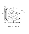
- Fig. 1 is a diagrammatic view of an ultrasonic testing scenario according to known techniques
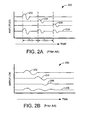
- Fig. 2A is a signal timing diagram according to known techniques
- Fig. 2B is another signal timing diagram according to known techniques
- Fig. 3 is a flow diagram depicting a method in accordance with an implementation
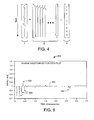
- Fig. 4 is a diagrammatic view depicting a mathematical relationship according to the present teachings.
- Fig. 5 is a flow diagram depicting a method in accordance with an implementation
- Fig. 6 is an illustrative signal timing diagram according to the present teachings.
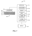
- Fig. 7 is a block diagram depicting a system in accordance with an implementation.
- the present disclosure teaches systems and methods for implementing long-wavelength ultrasonic testing and analysis of a laminar structure.
- Many specific details of certain embodiments of the disclosure are set forth in the following description and in Figures 1-7 to provide a thorough understanding of such embodiments.
- One skilled in the art, however, will understand that the disclosure may have additional embodiments, or that the disclosure may be implemented without several of the details described in the following description.
- Fig. 1 is a diagrammatic view of an ultrasonic testing scenario 100.
- the scenario 100 is illustrative and non-limiting, and is generally known in the related arts.
- the scenario 100 includes a transducer 102.
- the transducer 102 is configured to produce (i.e., emit) an ultrasonic pulse 104.
- the transducer 102 is further configured to receive (i.e., detect) ultrasonic echo signals 106 and to provide corresponding electrical signals (refer to Fig. 2 ).
- the scenario 100 also includes a laminate material 108 comprising a first layer 110 and a second layer 112.
- the first and second layers 110 and 112 are defined by thicknesses ⁇ 1 and ⁇ 2, respectively. While only two layers 110 and 112 are shown in the interest of simplicity, it is to be understood that other laminar materials having essentially any number of layers can be analyzed by way of ultrasonic testing.
- the transducer 102 emits an ultrasonic pulse 104 incident to the laminate material 108. Respective echoes 106 are reflected back from the surfaces and interfaces of the layers 110 and 112. The respective echoes 106 are detected by the transducer 102, which responds by producing corresponding time-domain electrical signals. The electrical signals from the transducer 102 are then digitized and recorded as echo data by instrumentation (refer to Fig. 7 ) coupled to the transducer 102. Furthermore, it is noted that internal reflections (echoes) 114 occur within the laminate material 108. Some of these internal echoes 114 are detected by the transducer 102 as echoes 106, while still others of the echoes 114 pass completely through the material or are internally absorbed. Thus, only a portion of the stimulus pulse 104 energy is recovered by way of the echoes 106.
- Fig. 2A is a signal timing diagram 200 including illustrative echo signals.
- the diagram 200 includes a first, a second and a third contributing echo 202, 204 and 206, respectively.
- the first echo 202 represents an ultrasonic pulse reflection off a surface adjacent to a transducer (e.g., 102) providing a stimulus pulse.
- the second echo 204 represents a reflection off of an interface between layers internal to a laminate material (e.g., 108).
- the third echo 206 represents a reflection off of the back surface of the laminate material distal to the transducer providing the stimulus pulse.
- the sum of the echoes 202-206 are detected (i.e., observed) by the corresponding transducer (e.g., 102), which in turn provides a corresponding electrical time-domain signal 208.
- the echo signals 202-206 are of regular sinusoidal form and represent echoes resulting from an ultrasonic pulse having a wavelength shorter than the respective layer thicknesses of the laminate material (e.g., 108) under analysis. As such, the echo signals 202-206 are readily distinguishable from one another and their individual characteristics (e.g., amplitude, period, etc.) can be subject to reliable analysis. It is further noted that the constant "c" designates wave propagation speed within the laminate structure.
- Fig. 2B is a signal timing diagram 250 including illustrative echo signals.
- Fig. 2B includes a first, a second and a third contributing echo 252, 254 and 256, respectively.
- the first echo 252 represents an ultrasonic pulse reflection off a surface adjacent to a transducer (e.g., 102) providing a stimulus pulse.
- the second echo 254 represents a reflection off of an interface between layers internal to a laminate material (e.g., 108).
- the third echo 256 represents a reflection off of the back surface of the laminate material distal to the transducer providing the stimulus pulse.
- the echo signals 252-256 are detected (i.e., observed) by the corresponding transducer (e.g., 102), which provides a corresponding electrical time-domain signal 258.
- the echo signals 252-256 are the result of an ultrasonic pulse (i.e., stimulus) having a wavelength greater than the respective layer thicknesses of the laminate material (e.g., 108) under analysis.
- the ultrasonic pulse can, in some implementations, have a wavelength longer than twice the thickness of one or more of the layers of the laminate material under test.
- the echo signals 252-256 are of generally sinusoidal form, the echo waveforms 252-256 at least partially overlap one another with respect to their arrival time at the transducer.
- the overall time-domain signal 258 provided by the transducer (e.g., 102) includes the summation of those overlapping signal 252-256 portions.
- the individual echoes 252-256 are not readily distinguishable within the electrical signal 258, and analysis of their respective characteristics is difficult or impossible under known techniques.
- Fig. 3 is a flow diagram 300 depicting a method in accordance with one implementation of the present teachings.
- the diagram 300 depicts particular method steps and order of execution. However, it is to be understood that other implementations can be used including other steps, omitting one or more depicted steps, and/or progressing in other orders of execution without departing from the scope of the present teachings.
- the method of the diagram 300 while be described with reference to Figs. 1 and 4 in the interest of understanding.
- a transducer e,g., 102 provides a stimulus (i.e., outgoing) pulse incident to a multi-layer, laminate material.
- the laminate material consists of several plies of individual thin-layer materials laid down as successive, contacting layers. Other laminate material structures can also be considered.
- the stimulus pulse is defined by a wavelength that is greater than twice the thickness of one or more of the layers of the laminate material subject to the pulse.
- the outgoing pulse is digitized and recorded as transducer pulse data.
- the outgoing pulse data is shifted by respective and incremental amounts so that a plurality of pulse vectors are defined. Any number of pulse vectors can be defined in this way such that an incrementally related set of vectors is formed.
- the outgoing pulse data can also be filtered, smoothed, and/or otherwise processed in accordance with known signal processing techniques prior to defining the plurality of pulse vectors.
- the pulse vectors defined at 304 above are assembled in a chronologically advancing order so as define a matrix " ⁇ " (phi). Reference is made to the matrix ⁇ of Fig. 4 . While the individual column vectors of the matrix ⁇ are depicted as waveforms in Fig. 4 , one of skill in the signal processing or related arts can appreciate that the actual vectors are comprised of suitable numerical values representing the digitally sampled (and possibly processed) outgoing pulse.
- the full waveforms echo signal is detected by the transducer (e.g., 102), converted to a corresponding time-domain electrical signal, digitized, and recorded. This resulting recorded, digitized, data is used to define an echo vector "Y".
- the echo data can be filtered, smoothed and/or otherwise processed according to known signal processing techniques prior to defining the echo vector Y. Reference is made to the echo vector Y of Fig. 4 .
- the echo vector Y is depicted in Fig. 4 as a waveform, but is understood to actually comprise suitable numerical values (quantification) of the digitally sampled (and possibly processed) echo waveform signal (e.g., 258).
- Y ⁇ * X
- a B-scan display of the sparse solution vector is performed by way of suitable electronic display and/or imaging equipment.
- the B-scan display format is familiar to one having ordinary skill in the non-destructive testing arts. Information regarding B-scan display can be found in: NDT Handbook, second edition, Birks et al. (technical editors), American Society for Nondestructive Testing, Columbus, Ohio, 1991 . Further information can also be found in: Ultrasonic Testing of Materials , second edition, Krautkramer et al., Berlin, New York, Springer-Verlag, 1977. Greater elaboration regarding B-scan displays is not needed for purposes herein.
- the B-scan display is then scrutinized by a user and/or automated means for purposes of identifying and measuring any anomalies within the laminate material under analysis. At this point, a typical, single operative instance of the method of diagram 300 is considered complete.
- Fig. 4 illustrates a mathematical relationship according to the present teachings.
- Fig. 5 is a flow diagram 500 depicting a method in accordance with one implementation of the present teachings.
- the diagram 500 depicts particular method steps and order of execution. However, it is to be understood that other implementations can be used including other steps, omitting one or more depicted steps, and/or progressing in other orders of execution without departing from the scope of the present teachings.
- the diagram 500 depicts one illustrative and non-limiting method for determining a sparse solution vector as that term was introduced above. In one non-limiting implementation, the method of diagram 500 is performed at 310 of Fig. 3 .
- a first feasible vector is derived in accordance with Equation 1 above.
- the term "feasible vector” refers to a vector which satisfies Equation 1 within a predetermined (i.e., user defined) tolerance.
- the first feasible vector includes S component (element) values.
- S nine component values
- the number of components S is equal to the number of pulse vectors (i.e., column vectors) in the corresponding matrix ⁇ .
- the absolute value of each of the S component values of the first feasible vector is calculated.
- the S absolute values are then summed to determine a summation value corresponding to the first feasible vector.
- Another feasible vector is derived in accordance with Equation 1 above.
- the other feasible vector like the first feasible vector, also includes S component (element) values.
- the absolute value of each of the S component values of the other feasible vector is calculated.
- the S absolute values are then summed to determine a summation value corresponding to the other feasible vector.
- the summation values of the first feasible vector and the other feasible vector are compared.
- the feasible vector with the lower summation value is selected and designated as the sparse feasible vector.
- the two most recently compared summation values indicate convergence within some tolerance. That is, the summation values are compared to determine if the differential between them is within some predetermined and user-definable value. If convergence is determined, the method proceeds to 516 below. If convergence is not determined, then the method proceeds to 514 below.
- the sparse feasible vector as designated at 510 above, is re-designated as the first feasible vector, and the summation value thereof is retained for comparative purposes. The method then proceeds back to 506 and a new other feasible vector is derived, processed and compared to the presently designated first feasible vector.
- the sparse feasible vector as designated at 510 above, is re-designated as the solution vector X.
- the sparse feasible vector as designated at 510 above, is re-designated as the solution vector X.
- the method of the diagram 500 is generally iterative in nature, usually - but not necessarily - requiring that a plurality R of feasible vectors x n be derived and compared in order to converge upon a final solution vector X for the echo data under consideration.
- the L1 Norm Solution is also referred to as "compressed sensing”.
- One illustrative and non-limiting solution vector X is depicted in Fig. 4 .
- the solution vector X of Fig. 4 includes only respective component values of unity (i.e., 1) and zero. However, it is important to note that in general, the solution vectors X can have non-unity values.
- Fig. 6 is a signal timing diagram 600 depicting a time-versus-amplitude plot of a solution vector (i.e., data) according to the present teachings.
- the diagram 600 is illustrative and non-limiting in nature, and is included in the interest of understanding the present teachings.
- the diagram 600 includes a time-domain signal 602 including numerous transients or "spikes" 604 corresponding to echoes detected during ultrasonic analysis of a laminate material. It is noted that the transients 604 are relatively distinct from one another, including readily discernable timing, amplitude and sign characteristics.
- the methods of the present teachings, wherein relatively long wavelength ultrasonic stimuli are used result in solution vector data that lends itself to ready interpretation by the user.
- the diagram 600 is not a B-scan display.
- Fig. 7 is a block diagrammatic view depicting an ultrasonic non-destructive testing system (system) 700 according to one illustrative and non-limiting implementation of the present teachings.
- the system 700 includes an ultrasonic transducer 702.
- the ultrasonic transducer 702 is configured to produce an ultrasonic pulse (i.e., stimulus) of predetermined characteristics such as, for example, amplitude, wavelength, and so on.
- the ultrasonic transducer 702 is further configured to detect any echoes that occur responsive to a stimulus pulse emitted by the ultrasonic transducer 702. Such detected echoes are converted to corresponding electrical signals by the ultrasonic transducer 702 and communicated to an apparatus 704.
- the apparatus 704 is configured to control the operation of the ultrasonic transducer 702 and to receive echo signals there from.
- the ultrasonic transducer 702 is depicted in Fig. 7 as being in operative contact with a laminate structure 706, which includes respective material layers 708, 710, 712 and 714.
- the apparatus 704 in the system 700 includes at least one processor 716, memory (i.e., computer-accessible storage) 718, and media 720 that includes program code 722.
- the processor(s) 716 is/are configured to operate, at least in part, in accordance with the program code included on media 720.
- the processor(s) 716 control(s) some, or all, of the operations and functions of the apparatus 704 including, among other things, operation of and communication with the transducer 702.
- the memory 718 is configured to be accessible to the processor(s) 716 such that data may be stored within and retrieved from the memory 718.
- the memory 718 can be defined by any suitable data (i.e., information) storage apparatus.
- Non-limiting examples of such memory 718 include random access memory (RAM), non-volatile storage memory, an optical data storage device, a magnetic storage device (disk drive), electrically erasable programmable read only memory (EEPROM), etc.
- RAM random access memory
- non-volatile storage memory an optical data storage device
- EEPROM electrically erasable programmable read only memory
- Other types of memory 718 may also be used.
- the media 720 can be defined by any suitable storage such as, for non-limiting example, random access memory (RAM), non-volatile solid-state storage memory, one or more optical data storage units (e.g., CD-ROM, DVD, etc.), one or more magnetic storage units (i.e., floppy disks and/or hard disks, etc.), electrically erasable programmable read only memory (EEPROM) devices, etc.
- RAM random access memory
- non-volatile solid-state storage memory one or more optical data storage units (e.g., CD-ROM, DVD, etc.), one or more magnetic storage units (i.e., floppy disks and/or hard disks, etc.), electrically erasable programmable read only memory (EEPROM) devices, etc.
- Other types of media 720 may also be used.
- the media 720 is defmed by one or more tangible, computer-accessible storage entities, of one or more types and/or configurations, which include program code compatible with the processor(s) 716.
- the apparatus 704 further includes other resources 724 as required and/or desired for operations of the apparatus 704.
- resources 724 include digital-to-analog conversion (DAC) circuitry, analog-to-digital conversion (ADC) circuitry, a power supply or other energy source(s), a user interface, network communications resources, wireless communications resources, application specific integrated circuitry (ASIC), various electronic circuitry, and so on.
- DAC digital-to-analog conversion
- ADC analog-to-digital conversion
- ASIC application specific integrated circuitry
- any suitable resources 724 can be included so as to enable some number of normal operations and functions of the apparatus 704.
- the apparatus 704 is defined, at least in part, by a computer.
- the system 700 further includes an electronic display 726.
- the display 726 is coupled in signal communication with the apparatus 704 so as to receive information (signals) there from and to graphically and/or textually present that information to a user.
- the display 726 is configured to provide a B-scan display of ultrasonic echo information in accordance with the present teachings.
- the display 726 can also be configured to present other types and/or formats of information display.
- the various elements of the system 700 are individually and cooperatively configured to perform at least some of the methods of the present teachings.
- the system 700 is configured to perform the methods depicted by Figs. 3 and 5 .
- Other suitable operations can also be performed by the system 700.
- the system 700 is illustrative and non-limiting with respect to the present teachings.
- only one ultrasonic transducer 702 is depicted, it is to be understood that any suitable number of transducers 702 may be used.
- more than one electronic display 726 can be included for simultaneous display of non-destructive testing data.
Landscapes
- Physics & Mathematics (AREA)
- General Physics & Mathematics (AREA)
- Immunology (AREA)
- Chemical & Material Sciences (AREA)
- Pathology (AREA)
- General Health & Medical Sciences (AREA)
- Biochemistry (AREA)
- Analytical Chemistry (AREA)
- Health & Medical Sciences (AREA)
- Life Sciences & Earth Sciences (AREA)
- Acoustics & Sound (AREA)
- Engineering & Computer Science (AREA)
- Signal Processing (AREA)
- Mathematical Analysis (AREA)
- Pure & Applied Mathematics (AREA)
- Algebra (AREA)
- Mathematical Physics (AREA)
- Mathematical Optimization (AREA)
- Investigating Or Analyzing Materials By The Use Of Ultrasonic Waves (AREA)
- Ultra Sonic Daignosis Equipment (AREA)
Applications Claiming Priority (1)
| Application Number | Priority Date | Filing Date | Title |
|---|---|---|---|
| US12/143,662 US7584062B1 (en) | 2008-06-20 | 2008-06-20 | Sub-wavelength ultrasound characterization of composite material |
Publications (3)
| Publication Number | Publication Date |
|---|---|
| EP2136207A2 true EP2136207A2 (fr) | 2009-12-23 |
| EP2136207A3 EP2136207A3 (fr) | 2012-12-19 |
| EP2136207B1 EP2136207B1 (fr) | 2016-11-09 |
Family
ID=41009244
Family Applications (1)
| Application Number | Title | Priority Date | Filing Date |
|---|---|---|---|
| EP09163210.9A Not-in-force EP2136207B1 (fr) | 2008-06-20 | 2009-06-19 | Caractérisation ultrasonore de sous-longueur d'onde d'un matériau composite basée sur la détection compressée |
Country Status (2)
| Country | Link |
|---|---|
| US (1) | US7584062B1 (fr) |
| EP (1) | EP2136207B1 (fr) |
Cited By (4)
| Publication number | Priority date | Publication date | Assignee | Title |
|---|---|---|---|---|
| CN104181233A (zh) * | 2014-08-26 | 2014-12-03 | 武汉大学 | 一种基于特征增强的耐张线夹压接缺陷超声b扫检测方法 |
| CN104739448A (zh) * | 2015-04-03 | 2015-07-01 | 深圳先进技术研究院 | 一种超声成像方法及装置 |
| CN106596724A (zh) * | 2016-12-08 | 2017-04-26 | 清华大学 | 一种窄带Lamb波检测数据稀疏压缩优化重建方法 |
| CN108414624A (zh) * | 2018-03-03 | 2018-08-17 | 北京工业大学 | 基于全波形反演法的起重机异形截面结构起重伸缩臂的检测方法 |
Families Citing this family (6)
| Publication number | Priority date | Publication date | Assignee | Title |
|---|---|---|---|---|
| US8359924B1 (en) * | 2010-07-01 | 2013-01-29 | The Boeing Company | Bond interface testing |
| US8965100B2 (en) * | 2012-01-20 | 2015-02-24 | The Boeing Company | Ultrasonic modeling for inspection of composite irregularities |
| US9595092B2 (en) | 2013-05-10 | 2017-03-14 | The Boeing Company | Methods and systems for inspection of composite irregularities |
| US9804130B2 (en) | 2015-05-08 | 2017-10-31 | The Boeing Company | System and method for providing simulated ultrasound porosity waveforms |
| US10094794B2 (en) | 2016-01-22 | 2018-10-09 | The Boeing Company | Characterization of wrinkles and periodic variations in material using infrared thermography |
| US11255825B2 (en) | 2016-10-31 | 2022-02-22 | The Boeing Company | Wrinkle characterization and performance prediction for composite structures |
Family Cites Families (4)
| Publication number | Priority date | Publication date | Assignee | Title |
|---|---|---|---|---|
| US4412315A (en) * | 1981-07-27 | 1983-10-25 | Texaco Inc. | Acoustic pulse-echo wall thickness method and apparatus |
| US5404755A (en) * | 1992-04-10 | 1995-04-11 | Olson Engineering, Inc. | Scanning apparatus and method for non-destructive materials evaluation and mapping through use of acoustic waves |
| US6301512B1 (en) * | 1993-12-30 | 2001-10-09 | The Boeing Company | Ultrasonic data analysis and display system |
| US7246522B1 (en) * | 2006-02-24 | 2007-07-24 | Battelle Memorial Institute | Methods and apparatus for multi-parameter acoustic signature inspection |
-
2008
- 2008-06-20 US US12/143,662 patent/US7584062B1/en not_active Expired - Fee Related
-
2009
- 2009-06-19 EP EP09163210.9A patent/EP2136207B1/fr not_active Not-in-force
Non-Patent Citations (2)
| Title |
|---|
| "NDT Handbook", 1991, AMERICAN SOCIETY FOR NONDESTRUCTIVE TESTING |
| KRAUTKRAMER ET AL.: "Ultrasonic Testing of Materials", 1977, SPRINGER-VERLAG |
Cited By (6)
| Publication number | Priority date | Publication date | Assignee | Title |
|---|---|---|---|---|
| CN104181233A (zh) * | 2014-08-26 | 2014-12-03 | 武汉大学 | 一种基于特征增强的耐张线夹压接缺陷超声b扫检测方法 |
| CN104739448A (zh) * | 2015-04-03 | 2015-07-01 | 深圳先进技术研究院 | 一种超声成像方法及装置 |
| CN106596724A (zh) * | 2016-12-08 | 2017-04-26 | 清华大学 | 一种窄带Lamb波检测数据稀疏压缩优化重建方法 |
| CN106596724B (zh) * | 2016-12-08 | 2019-05-07 | 清华大学 | 一种窄带Lamb波检测数据稀疏压缩优化重建方法 |
| CN108414624A (zh) * | 2018-03-03 | 2018-08-17 | 北京工业大学 | 基于全波形反演法的起重机异形截面结构起重伸缩臂的检测方法 |
| CN108414624B (zh) * | 2018-03-03 | 2020-11-03 | 北京工业大学 | 基于全波形反演法的起重机异形截面结构起重伸缩臂的检测方法 |
Also Published As
| Publication number | Publication date |
|---|---|
| EP2136207B1 (fr) | 2016-11-09 |
| US7584062B1 (en) | 2009-09-01 |
| EP2136207A3 (fr) | 2012-12-19 |
Similar Documents
| Publication | Publication Date | Title |
|---|---|---|
| EP2136207B1 (fr) | Caractérisation ultrasonore de sous-longueur d'onde d'un matériau composite basée sur la détection compressée | |
| Yu et al. | Crack imaging and quantification in aluminum plates with guided wave wavenumber analysis methods | |
| Baxter et al. | Delta T source location for acoustic emission | |
| Shi et al. | Ultrasonic and phased-array inspection in titanium-based alloys: A review | |
| Masserey et al. | High-frequency guided ultrasonic waves for hidden defect detection in multi-layered aircraft structures | |
| Eitzen et al. | Acoustic emission: establishing the fundamentals | |
| Dominguez et al. | Non-destructive imaging using the time domain topological energy method | |
| Jeon et al. | Damage detection on composite structures with standing wave excitation and wavenumber analysis | |
| EP2953545B1 (fr) | Procédé de recueil de données synthétiques pour capture en matrice complète à l'aide d'un réseau ultrasonore | |
| Spytek et al. | Evaluation of disbonds in adhesively bonded multilayer plates through local wavenumber estimation | |
| JP2018105844A (ja) | 複合材料構造物のためのリンクル特性評価及び性能予測 | |
| Ciampa et al. | Nonlinear elastic wave tomography for the imaging of corrosion damage | |
| US11709093B1 (en) | Three-dimensional broadband nonlinear phased array imaging | |
| Michaels | Ultrasonic wavefield imaging: Research tool or emerging NDE method? | |
| Etxaniz et al. | Ultrasound-based structural health monitoring methodology employing active and passive techniques | |
| He et al. | Application of pulse compression technique in metal materials cracks detection with LF-EMATs | |
| EP1474680B1 (fr) | Système et procédé de détection de défauts dans un objet fabriqué | |
| US20060048578A1 (en) | Method and apparatus for carrying out non-destructive testing of materials | |
| Samaitis et al. | Ultrasonic methods | |
| EP3546933B1 (fr) | Procédé et appareil de visualisation ultrasonore améliorée d'anomalies dans une structure | |
| Rozin et al. | Detecting selective laser melting beam power from ultrasonic temporal and spectral responses of phononic crystal artifacts toward in-situ real-time quality monitoring | |
| Carcreff et al. | Nonlinear beamforming based on amplitude coherence applied to ultrasonic imaging of coarse-grained steels | |
| Kumar | Total focusing method-based ultrasonic phased array imaging in thick structures | |
| Harvey et al. | Finite element analysis of ultrasonic phased array inspections on anisotropic welds | |
| Palanisamy et al. | Accurate and rapid acoustic damage characterization in complex structures using sparse sensor networks and deep learning models |
Legal Events
| Date | Code | Title | Description |
|---|---|---|---|
| PUAI | Public reference made under article 153(3) epc to a published international application that has entered the european phase |
Free format text: ORIGINAL CODE: 0009012 |
|
| 17P | Request for examination filed |
Effective date: 20090623 |
|
| AK | Designated contracting states |
Kind code of ref document: A2 Designated state(s): AT BE BG CH CY CZ DE DK EE ES FI FR GB GR HR HU IE IS IT LI LT LU LV MC MK MT NL NO PL PT RO SE SI SK TR |
|
| PUAL | Search report despatched |
Free format text: ORIGINAL CODE: 0009013 |
|
| AK | Designated contracting states |
Kind code of ref document: A3 Designated state(s): AT BE BG CH CY CZ DE DK EE ES FI FR GB GR HR HU IE IS IT LI LT LU LV MC MK MT NL NO PL PT RO SE SI SK TR |
|
| AX | Request for extension of the european patent |
Extension state: AL BA RS |
|
| RIC1 | Information provided on ipc code assigned before grant |
Ipc: G01N 29/11 20060101ALI20121109BHEP Ipc: G01N 29/06 20060101AFI20121109BHEP Ipc: G01N 29/04 20060101ALI20121109BHEP Ipc: G01N 29/34 20060101ALI20121109BHEP Ipc: G01N 29/44 20060101ALI20121109BHEP |
|
| GRAP | Despatch of communication of intention to grant a patent |
Free format text: ORIGINAL CODE: EPIDOSNIGR1 |
|
| INTG | Intention to grant announced |
Effective date: 20160527 |
|
| GRAS | Grant fee paid |
Free format text: ORIGINAL CODE: EPIDOSNIGR3 |
|
| GRAA | (expected) grant |
Free format text: ORIGINAL CODE: 0009210 |
|
| AK | Designated contracting states |
Kind code of ref document: B1 Designated state(s): AT BE BG CH CY CZ DE DK EE ES FI FR GB GR HR HU IE IS IT LI LT LU LV MC MK MT NL NO PL PT RO SE SI SK TR |
|
| REG | Reference to a national code |
Ref country code: GB Ref legal event code: FG4D |
|
| REG | Reference to a national code |
Ref country code: AT Ref legal event code: REF Ref document number: 844403 Country of ref document: AT Kind code of ref document: T Effective date: 20161115 Ref country code: CH Ref legal event code: EP |
|
| REG | Reference to a national code |
Ref country code: IE Ref legal event code: FG4D |
|
| REG | Reference to a national code |
Ref country code: DE Ref legal event code: R096 Ref document number: 602009042215 Country of ref document: DE |
|
| PG25 | Lapsed in a contracting state [announced via postgrant information from national office to epo] |
Ref country code: LV Free format text: LAPSE BECAUSE OF FAILURE TO SUBMIT A TRANSLATION OF THE DESCRIPTION OR TO PAY THE FEE WITHIN THE PRESCRIBED TIME-LIMIT Effective date: 20161109 |
|
| REG | Reference to a national code |
Ref country code: LT Ref legal event code: MG4D |
|
| REG | Reference to a national code |
Ref country code: NL Ref legal event code: MP Effective date: 20161109 |
|
| REG | Reference to a national code |
Ref country code: AT Ref legal event code: MK05 Ref document number: 844403 Country of ref document: AT Kind code of ref document: T Effective date: 20161109 |
|
| PG25 | Lapsed in a contracting state [announced via postgrant information from national office to epo] |
Ref country code: NL Free format text: LAPSE BECAUSE OF FAILURE TO SUBMIT A TRANSLATION OF THE DESCRIPTION OR TO PAY THE FEE WITHIN THE PRESCRIBED TIME-LIMIT Effective date: 20161109 Ref country code: SE Free format text: LAPSE BECAUSE OF FAILURE TO SUBMIT A TRANSLATION OF THE DESCRIPTION OR TO PAY THE FEE WITHIN THE PRESCRIBED TIME-LIMIT Effective date: 20161109 Ref country code: GR Free format text: LAPSE BECAUSE OF FAILURE TO SUBMIT A TRANSLATION OF THE DESCRIPTION OR TO PAY THE FEE WITHIN THE PRESCRIBED TIME-LIMIT Effective date: 20170210 Ref country code: NO Free format text: LAPSE BECAUSE OF FAILURE TO SUBMIT A TRANSLATION OF THE DESCRIPTION OR TO PAY THE FEE WITHIN THE PRESCRIBED TIME-LIMIT Effective date: 20170209 Ref country code: LT Free format text: LAPSE BECAUSE OF FAILURE TO SUBMIT A TRANSLATION OF THE DESCRIPTION OR TO PAY THE FEE WITHIN THE PRESCRIBED TIME-LIMIT Effective date: 20161109 |
|
| PG25 | Lapsed in a contracting state [announced via postgrant information from national office to epo] |
Ref country code: FI Free format text: LAPSE BECAUSE OF FAILURE TO SUBMIT A TRANSLATION OF THE DESCRIPTION OR TO PAY THE FEE WITHIN THE PRESCRIBED TIME-LIMIT Effective date: 20161109 Ref country code: HR Free format text: LAPSE BECAUSE OF FAILURE TO SUBMIT A TRANSLATION OF THE DESCRIPTION OR TO PAY THE FEE WITHIN THE PRESCRIBED TIME-LIMIT Effective date: 20161109 Ref country code: AT Free format text: LAPSE BECAUSE OF FAILURE TO SUBMIT A TRANSLATION OF THE DESCRIPTION OR TO PAY THE FEE WITHIN THE PRESCRIBED TIME-LIMIT Effective date: 20161109 Ref country code: PL Free format text: LAPSE BECAUSE OF FAILURE TO SUBMIT A TRANSLATION OF THE DESCRIPTION OR TO PAY THE FEE WITHIN THE PRESCRIBED TIME-LIMIT Effective date: 20161109 Ref country code: IS Free format text: LAPSE BECAUSE OF FAILURE TO SUBMIT A TRANSLATION OF THE DESCRIPTION OR TO PAY THE FEE WITHIN THE PRESCRIBED TIME-LIMIT Effective date: 20170309 Ref country code: PT Free format text: LAPSE BECAUSE OF FAILURE TO SUBMIT A TRANSLATION OF THE DESCRIPTION OR TO PAY THE FEE WITHIN THE PRESCRIBED TIME-LIMIT Effective date: 20170309 Ref country code: ES Free format text: LAPSE BECAUSE OF FAILURE TO SUBMIT A TRANSLATION OF THE DESCRIPTION OR TO PAY THE FEE WITHIN THE PRESCRIBED TIME-LIMIT Effective date: 20161109 |
|
| REG | Reference to a national code |
Ref country code: FR Ref legal event code: PLFP Year of fee payment: 9 |
|
| PG25 | Lapsed in a contracting state [announced via postgrant information from national office to epo] |
Ref country code: RO Free format text: LAPSE BECAUSE OF FAILURE TO SUBMIT A TRANSLATION OF THE DESCRIPTION OR TO PAY THE FEE WITHIN THE PRESCRIBED TIME-LIMIT Effective date: 20161109 Ref country code: DK Free format text: LAPSE BECAUSE OF FAILURE TO SUBMIT A TRANSLATION OF THE DESCRIPTION OR TO PAY THE FEE WITHIN THE PRESCRIBED TIME-LIMIT Effective date: 20161109 Ref country code: EE Free format text: LAPSE BECAUSE OF FAILURE TO SUBMIT A TRANSLATION OF THE DESCRIPTION OR TO PAY THE FEE WITHIN THE PRESCRIBED TIME-LIMIT Effective date: 20161109 Ref country code: CZ Free format text: LAPSE BECAUSE OF FAILURE TO SUBMIT A TRANSLATION OF THE DESCRIPTION OR TO PAY THE FEE WITHIN THE PRESCRIBED TIME-LIMIT Effective date: 20161109 Ref country code: SK Free format text: LAPSE BECAUSE OF FAILURE TO SUBMIT A TRANSLATION OF THE DESCRIPTION OR TO PAY THE FEE WITHIN THE PRESCRIBED TIME-LIMIT Effective date: 20161109 |
|
| REG | Reference to a national code |
Ref country code: DE Ref legal event code: R097 Ref document number: 602009042215 Country of ref document: DE |
|
| PG25 | Lapsed in a contracting state [announced via postgrant information from national office to epo] |
Ref country code: IT Free format text: LAPSE BECAUSE OF FAILURE TO SUBMIT A TRANSLATION OF THE DESCRIPTION OR TO PAY THE FEE WITHIN THE PRESCRIBED TIME-LIMIT Effective date: 20161109 Ref country code: BG Free format text: LAPSE BECAUSE OF FAILURE TO SUBMIT A TRANSLATION OF THE DESCRIPTION OR TO PAY THE FEE WITHIN THE PRESCRIBED TIME-LIMIT Effective date: 20170209 Ref country code: BE Free format text: LAPSE BECAUSE OF FAILURE TO SUBMIT A TRANSLATION OF THE DESCRIPTION OR TO PAY THE FEE WITHIN THE PRESCRIBED TIME-LIMIT Effective date: 20161109 |
|
| PLBE | No opposition filed within time limit |
Free format text: ORIGINAL CODE: 0009261 |
|
| STAA | Information on the status of an ep patent application or granted ep patent |
Free format text: STATUS: NO OPPOSITION FILED WITHIN TIME LIMIT |
|
| 26N | No opposition filed |
Effective date: 20170810 |
|
| PG25 | Lapsed in a contracting state [announced via postgrant information from national office to epo] |
Ref country code: SI Free format text: LAPSE BECAUSE OF FAILURE TO SUBMIT A TRANSLATION OF THE DESCRIPTION OR TO PAY THE FEE WITHIN THE PRESCRIBED TIME-LIMIT Effective date: 20161109 |
|
| PG25 | Lapsed in a contracting state [announced via postgrant information from national office to epo] |
Ref country code: MC Free format text: LAPSE BECAUSE OF FAILURE TO SUBMIT A TRANSLATION OF THE DESCRIPTION OR TO PAY THE FEE WITHIN THE PRESCRIBED TIME-LIMIT Effective date: 20161109 |
|
| REG | Reference to a national code |
Ref country code: CH Ref legal event code: PL |
|
| REG | Reference to a national code |
Ref country code: IE Ref legal event code: MM4A |
|
| PG25 | Lapsed in a contracting state [announced via postgrant information from national office to epo] |
Ref country code: LI Free format text: LAPSE BECAUSE OF NON-PAYMENT OF DUE FEES Effective date: 20170630 Ref country code: CH Free format text: LAPSE BECAUSE OF NON-PAYMENT OF DUE FEES Effective date: 20170630 Ref country code: IE Free format text: LAPSE BECAUSE OF NON-PAYMENT OF DUE FEES Effective date: 20170619 Ref country code: LU Free format text: LAPSE BECAUSE OF NON-PAYMENT OF DUE FEES Effective date: 20170619 |
|
| REG | Reference to a national code |
Ref country code: FR Ref legal event code: PLFP Year of fee payment: 10 |
|
| PG25 | Lapsed in a contracting state [announced via postgrant information from national office to epo] |
Ref country code: MT Free format text: LAPSE BECAUSE OF NON-PAYMENT OF DUE FEES Effective date: 20170619 |
|
| PG25 | Lapsed in a contracting state [announced via postgrant information from national office to epo] |
Ref country code: HU Free format text: LAPSE BECAUSE OF FAILURE TO SUBMIT A TRANSLATION OF THE DESCRIPTION OR TO PAY THE FEE WITHIN THE PRESCRIBED TIME-LIMIT; INVALID AB INITIO Effective date: 20090619 |
|
| PG25 | Lapsed in a contracting state [announced via postgrant information from national office to epo] |
Ref country code: CY Free format text: LAPSE BECAUSE OF NON-PAYMENT OF DUE FEES Effective date: 20161109 |
|
| PG25 | Lapsed in a contracting state [announced via postgrant information from national office to epo] |
Ref country code: MK Free format text: LAPSE BECAUSE OF FAILURE TO SUBMIT A TRANSLATION OF THE DESCRIPTION OR TO PAY THE FEE WITHIN THE PRESCRIBED TIME-LIMIT Effective date: 20161109 |
|
| PG25 | Lapsed in a contracting state [announced via postgrant information from national office to epo] |
Ref country code: TR Free format text: LAPSE BECAUSE OF FAILURE TO SUBMIT A TRANSLATION OF THE DESCRIPTION OR TO PAY THE FEE WITHIN THE PRESCRIBED TIME-LIMIT Effective date: 20161109 |
|
| PGFP | Annual fee paid to national office [announced via postgrant information from national office to epo] |
Ref country code: FR Payment date: 20200625 Year of fee payment: 12 Ref country code: DE Payment date: 20200629 Year of fee payment: 12 |
|
| PGFP | Annual fee paid to national office [announced via postgrant information from national office to epo] |
Ref country code: GB Payment date: 20200629 Year of fee payment: 12 |
|
| REG | Reference to a national code |
Ref country code: DE Ref legal event code: R082 Ref document number: 602009042215 Country of ref document: DE Representative=s name: KILBURN & STRODE LLP, NL |
|
| REG | Reference to a national code |
Ref country code: DE Ref legal event code: R119 Ref document number: 602009042215 Country of ref document: DE |
|
| GBPC | Gb: european patent ceased through non-payment of renewal fee |
Effective date: 20210619 |
|
| PG25 | Lapsed in a contracting state [announced via postgrant information from national office to epo] |
Ref country code: GB Free format text: LAPSE BECAUSE OF NON-PAYMENT OF DUE FEES Effective date: 20210619 Ref country code: DE Free format text: LAPSE BECAUSE OF NON-PAYMENT OF DUE FEES Effective date: 20220101 |
|
| PG25 | Lapsed in a contracting state [announced via postgrant information from national office to epo] |
Ref country code: FR Free format text: LAPSE BECAUSE OF NON-PAYMENT OF DUE FEES Effective date: 20210630 |