EP2135802A1 - Vehicle seat used outdoors - Google Patents
Vehicle seat used outdoors Download PDFInfo
- Publication number
- EP2135802A1 EP2135802A1 EP08738675A EP08738675A EP2135802A1 EP 2135802 A1 EP2135802 A1 EP 2135802A1 EP 08738675 A EP08738675 A EP 08738675A EP 08738675 A EP08738675 A EP 08738675A EP 2135802 A1 EP2135802 A1 EP 2135802A1
- Authority
- EP
- European Patent Office
- Prior art keywords
- highly
- surface skin
- bottom plate
- end portion
- expanding member
- Prior art date
- Legal status (The legal status is an assumption and is not a legal conclusion. Google has not performed a legal analysis and makes no representation as to the accuracy of the status listed.)
- Granted
Links
- XLYOFNOQVPJJNP-UHFFFAOYSA-N water Substances O XLYOFNOQVPJJNP-UHFFFAOYSA-N 0.000 claims abstract description 86
- 239000000463 material Substances 0.000 claims abstract description 43
- 239000000835 fiber Substances 0.000 claims description 36
- 239000004744 fabric Substances 0.000 claims description 21
- 239000002253 acid Substances 0.000 claims description 11
- 159000000000 sodium salts Chemical class 0.000 claims description 11
- 210000002268 wool Anatomy 0.000 claims description 9
- 239000000843 powder Substances 0.000 claims description 4
- 230000000149 penetrating effect Effects 0.000 abstract description 15
- -1 polypropylene Polymers 0.000 description 8
- 238000000034 method Methods 0.000 description 7
- 239000004743 Polypropylene Substances 0.000 description 6
- 230000006866 deterioration Effects 0.000 description 6
- 238000007789 sealing Methods 0.000 description 6
- 239000011230 binding agent Substances 0.000 description 5
- 230000000694 effects Effects 0.000 description 5
- 230000035515 penetration Effects 0.000 description 5
- 239000011347 resin Substances 0.000 description 5
- 229920005989 resin Polymers 0.000 description 5
- 239000004698 Polyethylene Substances 0.000 description 4
- 238000010521 absorption reaction Methods 0.000 description 4
- 150000002500 ions Chemical class 0.000 description 4
- 229920001155 polypropylene Polymers 0.000 description 4
- 239000006260 foam Substances 0.000 description 3
- 239000010985 leather Substances 0.000 description 3
- 230000003204 osmotic effect Effects 0.000 description 3
- 229920000139 polyethylene terephthalate Polymers 0.000 description 3
- 239000005020 polyethylene terephthalate Substances 0.000 description 3
- 238000012545 processing Methods 0.000 description 3
- 238000009958 sewing Methods 0.000 description 3
- BZHJMEDXRYGGRV-UHFFFAOYSA-N Vinyl chloride Chemical compound ClC=C BZHJMEDXRYGGRV-UHFFFAOYSA-N 0.000 description 2
- 239000000853 adhesive Substances 0.000 description 2
- 230000001070 adhesive effect Effects 0.000 description 2
- 125000003178 carboxy group Chemical group [H]OC(*)=O 0.000 description 2
- 239000002649 leather substitute Substances 0.000 description 2
- 238000004806 packaging method and process Methods 0.000 description 2
- 229920000573 polyethylene Polymers 0.000 description 2
- 239000012254 powdered material Substances 0.000 description 2
- 229910052708 sodium Inorganic materials 0.000 description 2
- 239000011734 sodium Substances 0.000 description 2
- 229920002972 Acrylic fiber Polymers 0.000 description 1
- 229920000049 Carbon (fiber) Polymers 0.000 description 1
- 229920000742 Cotton Polymers 0.000 description 1
- JOYRKODLDBILNP-UHFFFAOYSA-N Ethyl urethane Chemical compound CCOC(N)=O JOYRKODLDBILNP-UHFFFAOYSA-N 0.000 description 1
- DGAQECJNVWCQMB-PUAWFVPOSA-M Ilexoside XXIX Chemical compound C[C@@H]1CC[C@@]2(CC[C@@]3(C(=CC[C@H]4[C@]3(CC[C@@H]5[C@@]4(CC[C@@H](C5(C)C)OS(=O)(=O)[O-])C)C)[C@@H]2[C@]1(C)O)C)C(=O)O[C@H]6[C@@H]([C@H]([C@@H]([C@H](O6)CO)O)O)O.[Na+] DGAQECJNVWCQMB-PUAWFVPOSA-M 0.000 description 1
- VYPSYNLAJGMNEJ-UHFFFAOYSA-N Silicium dioxide Chemical compound O=[Si]=O VYPSYNLAJGMNEJ-UHFFFAOYSA-N 0.000 description 1
- FAPWRFPIFSIZLT-UHFFFAOYSA-M Sodium chloride Chemical compound [Na+].[Cl-] FAPWRFPIFSIZLT-UHFFFAOYSA-M 0.000 description 1
- 229920000122 acrylonitrile butadiene styrene Polymers 0.000 description 1
- 239000004917 carbon fiber Substances 0.000 description 1
- 238000006243 chemical reaction Methods 0.000 description 1
- 238000010276 construction Methods 0.000 description 1
- 238000006073 displacement reaction Methods 0.000 description 1
- 239000006261 foam material Substances 0.000 description 1
- 238000005187 foaming Methods 0.000 description 1
- 239000003365 glass fiber Substances 0.000 description 1
- 238000002347 injection Methods 0.000 description 1
- 239000007924 injection Substances 0.000 description 1
- 238000004519 manufacturing process Methods 0.000 description 1
- 238000002844 melting Methods 0.000 description 1
- 230000008018 melting Effects 0.000 description 1
- 238000012805 post-processing Methods 0.000 description 1
- 239000012783 reinforcing fiber Substances 0.000 description 1
- 150000003839 salts Chemical group 0.000 description 1
- 239000000741 silica gel Substances 0.000 description 1
- 229910002027 silica gel Inorganic materials 0.000 description 1
- 229910001415 sodium ion Inorganic materials 0.000 description 1
- 239000000243 solution Substances 0.000 description 1
- 239000012209 synthetic fiber Substances 0.000 description 1
- 229920002994 synthetic fiber Polymers 0.000 description 1
- 235000013311 vegetables Nutrition 0.000 description 1
Images


Classifications
-
- B—PERFORMING OPERATIONS; TRANSPORTING
- B60—VEHICLES IN GENERAL
- B60N—SEATS SPECIALLY ADAPTED FOR VEHICLES; VEHICLE PASSENGER ACCOMMODATION NOT OTHERWISE PROVIDED FOR
- B60N2/00—Seats specially adapted for vehicles; Arrangement or mounting of seats in vehicles
- B60N2/58—Seat coverings
- B60N2/5816—Seat coverings attachments thereof
- B60N2/5825—Seat coverings attachments thereof by hooks, staples, clips, snap fasteners or the like
-
- B—PERFORMING OPERATIONS; TRANSPORTING
- B60—VEHICLES IN GENERAL
- B60N—SEATS SPECIALLY ADAPTED FOR VEHICLES; VEHICLE PASSENGER ACCOMMODATION NOT OTHERWISE PROVIDED FOR
- B60N2/00—Seats specially adapted for vehicles; Arrangement or mounting of seats in vehicles
- B60N2/58—Seat coverings
- B60N2/5816—Seat coverings attachments thereof
- B60N2/5883—Seat coverings attachments thereof by sewing, stitching or threading
-
- B—PERFORMING OPERATIONS; TRANSPORTING
- B62—LAND VEHICLES FOR TRAVELLING OTHERWISE THAN ON RAILS
- B62J—CYCLE SADDLES OR SEATS; AUXILIARY DEVICES OR ACCESSORIES SPECIALLY ADAPTED TO CYCLES AND NOT OTHERWISE PROVIDED FOR, e.g. ARTICLE CARRIERS OR CYCLE PROTECTORS
- B62J1/00—Saddles or other seats for cycles; Arrangement thereof; Component parts
- B62J1/12—Box-shaped seats; Bench-type seats, e.g. dual or twin seats
-
- B—PERFORMING OPERATIONS; TRANSPORTING
- B62—LAND VEHICLES FOR TRAVELLING OTHERWISE THAN ON RAILS
- B62J—CYCLE SADDLES OR SEATS; AUXILIARY DEVICES OR ACCESSORIES SPECIALLY ADAPTED TO CYCLES AND NOT OTHERWISE PROVIDED FOR, e.g. ARTICLE CARRIERS OR CYCLE PROTECTORS
- B62J1/00—Saddles or other seats for cycles; Arrangement thereof; Component parts
- B62J1/18—Covers for saddles or other seats; Paddings
Definitions
- the present invention relates to an outdoor vehicle seat, in particular to an outdoor vehicle seat for preventing deterioration due to water penetration.
- a sealing member is arranged at the joint portion of a seat surface skin end portion and a bottom plate (for example, refer to Patent Document 1).
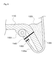
- a surface skin end portion 130a of the seat and an elastic sealing member 150 are jointed at a stitched portion 160 by machine-sewing, and the surface skin end portion 130a to which the elastic sealing member 150 is jointed, and a bottom plate 110 on which a cushioning material 120 is arranged are jointed by a fixing member 140 such as a staple and the like.
- Patent Document 1 Japanese Unexamined Patent Application Publication No. 9-286364
- the waterproof structure of the surface skin end portion used in the seat described in the Patent Document 1 there are cases where water cannot be prevented from penetrating from the portion between the elastic sealing member 150 and the bottom plate.
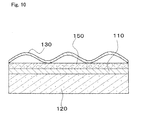
- the surface skin end portion is attached with crimples due to surface skin surplus, and as shown in FIG. 10 , a gap is formed between the surface skin 130 and the elastic sealing member 150 in some cases.
- water penetrates from this gap into the inside of the seat, and water cannot be completely prevented from penetrating in the seat inside, as a result, water is absorbed in the cushioning material in the seat inside, and deterioration of the cushioning material leads to declined seat function.
- the object of the present invention is to provide an outdoor vehicle seat that prevents water from penetrating from the stitched portion of the surface skin, or the portion between the surface skin end portion and the bottom plate.
- an outdoor vehicle seat that is formed by arranging a cushioning material on a bottom plate, and covering the cushioning material with a surface skin, and fixing a surface skin end portion to the bottom plate, wherein a highly water absorbing, highly moisture absorbing, and highly expanding member is arranged between the surface skin end portion and the bottom plate.
- the highly water absorbing, highly moisture absorbing, and highly expanding member is arranged between the surface skin end portion and the bottom plate, it is possible to rapidly absorb water penetrating from the gap between the surface skin end portion and the bottom plate, and seal up the gap completely by the expansion thereof, and prevent water from penetrating into the seat inside. Accordingly, it is possible to prevent the seat function from declining due to the deterioration of the cushioning material by water penetration into the seat inside.
- an expanding member containing portion for arranging the highly water absorbing, highly moisture absorbing, and highly expanding member is formed at the portion to contact the surface skin end portion of the back side.
- the expanding member containing portion in the bottom plate, it is possible to secure the place to contain the expanding member and position and fix it, and thereby it is possible to improve the workability in manufacture processes.
- an outdoor vehicle seat that is formed by arranging a cushioning material on a bottom plate, and covering the cushioning material with a surface skin, and fixing a surface skin end portion to the bottom plate, wherein the surface skin includes a covering surface skin for covering the cushioning material, a jointing surface skin for structuring the surface skin end portion to be fixed to the bottom plate, and a stitched portion to sew together the covering surface skin and the jointing surface skin, and a highly water absorbing, highly moisture absorbing, and highly expanding member is arranged, between the covering end portion and the jointing end portion, in the stitched portion.
- the highly water absorbing, highly moisture absorbing, and highly expanding member is arranged between the covering end portion and the jointing end portion of stotched portrion, it is possible to rapidly absorb water penetrating from the stitched portion, and seal off further penetration of water completely, by the expansion thereof, and prevent water from penetrating into the seat inside. Accordingly, it is possible to prevent the seat function from declining due to the deterioration of the cushioning material by water penetration into the seat inside.
- the highly water absorbing, highly moisture absorbing, and highly expanding member has airspaces.
- the expanding member has airspaces, it is possible to absorb expansion amount accompanying expansion by the airspaces, prevent the expanding member from coming out from the stitched portion, and prevent the fixing member and the like from dropping down or the sewed portion from being damaged in end processed portion and sewed portion, which is caused by expansion of the expanding member.
- the highly water absorbing, highly moisture absorbing, and highly expanding member includes at least highly water absorbing, highly moisture absorbing, and highly expanding fibers that are fibers of a highly water absorbing, highly moisture absorbing, and highly expanding material.
- the highly water absorbing, highly moisture absorbing, and highly expanding material includes at least highly water absorbing, highly moisture absorbing, and highly expanding fibers that are fibers of a highly water absorbing, highly moisture absorbing, and highly expanding material.
- the highly water absorbing, highly moisture absorbing, and highly expanding member is powders of a highly water absorbing, highly moisture absorbing, and highly expanding material packaged by nonwoven cloth or coarse wool cloth.
- the powdered highly water absorbing, highly moisture absorbing, and highly expanding material can be used without a special process, and accordingly it is possible to reduce the number of processes.
- the highly water absorbing, highly moisture absorbing, and highly expanding material is made of bridged polyacryl acid sodium salt.
- bridged polyacryl acid sodium salt it is possible, by its high water absorbing, highly moisture absorbing, and highly expanding property, to absorb water further more rapidly, and seal up the gap completely by the expansion thereof, and prevent water from further penetrating into the seat inside.
- the highly water absorbing, highly moisture absorbing, and highly expanding member is arranged between the surface skin end portion and the bottom plate, or between the covering surface skin and the jointing surface skin, it is possible to rapidly absorb water penetrating inside, and seal up the gap completely by the expansion thereof, and prevent water from penetrating into the seat inside. Accordingly, it is possible to prevent the seat function from declining due to the deterioration of the cushioning material by water penetration into the seat inside.
- FIG. 1 through FIG. 4 show a first preferred embodiment according to the present invention
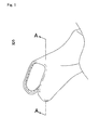
- FIG. 1 is a partial perspective view of an outdoor vehicle seat
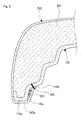
- FIG. 2 is a partial cross sectional view at A-A in FIG. 1
- FIG. 3 is an explanatory figure showing the arrangement of an expanding member
- FIG. 4 is an explanatory figure showing the arrangement of an expanding member as another example
- FIG. 5 is an explanatory figure showing the arrangement of an expanding member as still another example
- FIG. 6 is an explanatory figure showing the arrangement of an expanding member as yet another example
- FIG. 7 is an explanatory figure showing a waterproof effect.
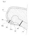
- FIG. 8 is a partial cross sectional view showing another preferred embodiment.
- the outdoor vehicle seat S includes not only seats for two-wheel vehicles, that is, land motorbikes, and scooters, but also seats for snowmobiles, personal watercraft and the like, and further includes vehicle seats for three-wheel buggies and the like and riding type passenger vehicles, or construction machines.
- the outdoor vehicle seat S is, as shown in FIG. 1 and FIG. 2 , formed by placing a cushioning material 20 on a bottom plate 10, and covering them with a surface skin 30. Further, a surface skin end portion 30a of the surface skin 30 is attached onto the bottom plate 10 with a fixing member 40 such as a staple and the like in the back side of the bottom plate 10.
- the bottom plate 10 is injection molded of for example PP (polypropylene), ABS resin and the like, in order to secure its rigidity. Further, a bottom plate 10 formed of PPG (polypropylene including glass fibers), PPF (polypropylene including feller) may be used, and thereby it is possible to secure the rigidity without increasing the weight of the bottom plate 10. In the PPT, as reinforcing fibers, for example carbon fibers are mixed.
- the cushioning material 20 is formed of soft foam materials, for example, urethane foam, PP (polypropylene) foam, PE (polyethylene) foam, and is arranged on the bottom plate 10.
- soft foam materials for example, urethane foam, PP (polypropylene) foam, PE (polyethylene) foam, and is arranged on the bottom plate 10.
- the surface skin 30 is made of, for example, vinyl chloride resin leather, artificial leather, natural leather and the like. Meanwhile, in the case of outdoor vehicle seats used outdoors, such as two-wheel vehicle seats and the like, like in the present preferred embodiment, it is preferable to form the surface skin of vinyl chloride resin leather and artificial leather and the like.
- the bottom plate 10 is equipped with a surface skin contact portion 10a, a surface skin fixing portion 10b, and an expanding member containing portion 10c.
- the surface skin contact portion 10a is formed of the end portion of the bottom plate 10 and the back side of the bottom plate 10 bent from the end portion in L-shape, and the surface skin fixing portion 10b is formed at the position a specified distance away from the surface skin contact portion 10a in the back side of the bottom plate 10, and the expanding member containing portion 10c is formed along the circumference of the bottom plate 10 between the surface skin contact portion 10a and the surface skin fixing portion 10b of the bottom plate 10.
- This expanding member containing portion 10c is bent from the back side to the cushioning material 20 as a step portion.
- the surface skin 30 is so formed as to contact the bottom plate 10 at the portion of the surface skin contact portion 10a and go to the back side, via the expanding member containing portion 10c, and fix the surface skin end portion 30a of the surface skin 30 with the surface skin fixing portion 10b.
- the expanding member 50 according to the present preferred embodiment, as shown in FIG. 2 and FIG. 3 , after the expanding member 50 formed into a band shape is put on the expanding member containing portion 10c, and is covered with the surface skin end portion 30a of the surface skin 30, and then is fixed to the bottom plate 10 by the fixing member 40 such as a staple and the like, is fixed at the same time.
- the expanding member 50 is arranged in the expanding member containing portion 10c of the bottom plate 10, and covered with the surface skin end portion 30a, and is fixed together with the surface skin end portion 30a, and accordingly it is possible to position and fix the expanding member 50, without using a new fixing member to fix the expanding member 50. Further, it is possible to reduce the number of parts and the number of processes accompanying the assembly.
- an expanding member 50 formed into a band shape may be adhered to the surface skin end portion 30a by adhesive and the like beforehand, and then the expanding member 50 may be adhered to the expanding member containing portion 10c of the bottom plate 10, and may be fixed with the fixing member 40 such as a staple and the like.
- the fixing member 40 such as a staple and the like.
- the expanding member 50 may be adhered to the expanding member containing portion 10c of the bottom plate 10 by adhesive and the like beforehand, then covered with the surface skin 30, and fixed by the fixing member 40 such as a staple and the like.
- the fixing member 40 such as a staple and the like.
- this band shaped member may be, as shown in FIG. 4 , an expanding member 50 in which airspaces 51 are arranged.
- this band shaped member may be, as shown in FIG. 4 , an expanding member 50 in which airspaces 51 are arranged.
- the number, and interval of the airspaces 51 it is possible to adjust the water absorption amount by the expanding member 50 and the expansion rate.
- the number of the airspaces 51 may be increased, and the use amount of the expanding member 50 may be adjusted.
- the number thereof may be adjusted.
- the space formed by the expanding member containing portion 10c becomes narrower, and accordingly it is possible to seal off the space with smaller expansion of the expanding member 50. That is, it is possible to increase the number of the airspaces 51, and reduce the use amount of the expanding member 50.
- the present invention is not limited to the example shown in FIG. 4 , but as shown in FIG. 5 , the expanding member 50 may be formed of plural convex portions 52 and concave portions 53. Moreover, as shown in FIG. 6 , the expanding member 50 may be devided into plural pieces 54, which are arranged at specified intervals. Meanwhile, this interval is not necessarily constant, but may be changed appropriately according to applications. Thus, by appropriately adjusting the numbers of the convex portions 52 and the concave portions 53, and the arrangement intervals and number of the devided pieces 54, it is possible to obtain the same effect as mentioned previously.
- the expanding member 50 is not specifically limited, as long as it has high expanding property by water, and in the present preferred embodiment, nonwoven cloth, or coarse wool cloth including at least highly water absorbing, highly moisture absorbing, and highly expanding fibers that absorb water on contacting water and expand is employed.
- nonwoven cloth or coarse wool cloth including at least highly water absorbing, highly moisture absorbing, and highly expanding fibers
- base fibers made of resin, and highly water absorbing, highly moisture absorbing, and highly expanding fibers obtained by making a highly water absorbing, highly moisture absorbing, and highly expanding material into fibers are softened by heat at processing and combined mutually and made into nonwoven cloth, or, those where base fibers made of resin, and highly water absorbing, highly moisture absorbing, and highly expanding fibers obtained by making a highly water absorbing, highly moisture absorbing, and highly expanding material into fibers, are combined via a binder solved by heat at processing and made into nonwoven cloth, and the like may be employed.
- PET polyethylene terephthalate
- PE polyethylene
- the base fibers for example PET (polyethylene terephthalate) fibers and PE (polyethylene) fibers may be used.
- the highly water absorbing, highly moisture absorbing, and highly expanding fibers bridged polyacryl acid sodium salt system fibers, fibers where the surface of acrylic fibers is hydrolyzed by post processing and the like may be used.
- the binder low melting point PET that solved by heat at processing and the like may be employed.
- bridged polyacryl acid sodium salt system fibers that can absorb and hold a large amount of water by ion osmotic pressure, and little take off from the water even under load or external force are used.
- the bridged polyacryl acid sodium salt system fibers has 45 times the absorbing performance of its own weight in normal saline solution, and 150% the moisture absorbing performance under 95% relative moisture, and has the moisture absorbing performance approximately 7 times of cotton, and approximately twice of B type silica gel.
- This bridged polyacryl acid sodium salt is salt having sodium carboxylate (COONa)at its end group.
- carboxyl groups and sodium that structure the end group separate off and ionize.
- water absorption starts by osmotic pressure occurring by the concentration differences of sodium ions, and at the same time, carboxyl groups that have become negative ions act repulsively and intermolecular space expands.
- FIG. 7 is an explanatory figure showing a waterproof effect.
- FIG. 7A in the surface skin 30, when front and rear curved portions of the bottom plate 10 are covered, since there occurs surplus of the surface skin end portion, the surplus portions are collected up and fixed so that the surface skin end portion should overlap (should cause crimples), and accordingly, gaps are formed between the surface skin 30 and the bottom plate 10. And, when water penetrates in from the gaps, water is absorbed by the expanding member 50.
- the expanding member 50 the bridged polyacryl acid sodium salt is employed as the expanding member 50.
- the expanding member absorbs incoming water more rapidly, and rapidly expands so as to seal up the gaps formed between the surface skin 30 and the bottom plate 10.
- FIG. 7B it is possible to completely seal up the gaps formed between the surface skin 30 and the bottom plate 10, and reliably prevent water from penetrating into the inside of the seat.
- the expanding member 50 is arranged between the surface skin 30 and the bottom plate 10, and accordingly it is possible to prevent water from penetrating into the inside of the seat, and prevent the weight of the entire seat from increasing, and prevent the seat function from declining. Further, the expanding member 50 is arranged in the containing space formed by the expanding member containing portion 10c of the bottom plate 10 and the surface skin end portion 30a, and accordingly it is possible to position and fix the expanding member 50, without using a new fixing member to fix the expanding member 50.
- nonwoven cloth, or coarse wool cloth including at least highly water absorbing, highly moisture absorbing, and highly expanding fibers are employed, and accordingly, by rapid water absorption and expansion, it is possible to seal up gaps formed by crimples of the surface skin more rapidly, and reliably prevent water from penetrating into the inside of the seat.
- FIG. 8 is a figure showing a second preferred embodiment, and in this second preferred embodiment, an identical code is allotted to a same member as in the first preferred embodiment, and repeated explanations thereof are omitted.
- the present preferred embodiment is one where the expanding member 50 is used at a surface skin joint stitched portion 60 of an outdoor vehicle seat.
- the surface skin 30 in the present preferred embodiment is formed so that, a covering surface skin end portion 31a of a covering surface skin 31 for covering a cushioning material 20, and jointing surface skin end portion 32a of a jointing surface skin 32 fixed to a bottom plate 10 with a fixing member 40 such as a staple and the like are sewed together so as to overlap at the surface skin joint stitched portion 60.
- the expanding member 50 is arranged along their overlapped portion, and the covering surface skin end portion 31a, the jointing surface skin end portion 32a, and the expanding member 50 are sewed together as a body by machine-sewing and the like.
- the expanding member 50 is arranged between the covering surface skin 31 and the jointing surface skin 32, and accordingly it is possible to prevent water from penetrating into the inside of the seat, and prevent the seat function from declining. Further, the covering surface skin end portion 31a, the jointing surface skin end portion 32a, and the expanding member 50 are sewed together as a body at the surface skin joint stitched portion 60, and accordingly it is possible to reliably fix the expanding member 50 to the overlapped portion of the covering surface skin end portion 31a and the jointing surface skin end portion 32a.
- the covering surface skin end portion 31a, the jointing surface skin end portion 32a, and the expanding member 50 are firmly sewed together by machine-sewing and the like at the surface skin joint stitched portion 60, without using a fixing member such as a staple and the like, and accordingly it is possible to prevent a fixing member from dropping off due to expansion of the expanding member 50.
- the expanding member highly water absorbing, highly moisture absorbing, and highly expanding fibers combined with base fibers with a binder and the like are employed.
- powders of a highly water absorbing, highly moisture absorbing, and highly expanding material made of bridged polyacryl acid sodium salt and the like packaged with an air ventilating material such as nonwoven cloth, or coarse wool cloth may be employed.
- the air ventilating material such as nonwoven cloth, or coarse wool cloth
- the powdered material can be used without a special process, and accordingly it is possible to reduce the number of processes.
- the air ventilating material such as nonwoven cloth, or coarse wool cloth used herein is to prevent the powdered highly water absorbing, highly moisture absorbing, and highly expanding material from leaking, and let incoming water and steam go through, therefore, nonwoven cloth such as normal vegetable fibers, animal fibers, recycled fibers, synthetic fibers and the like, or a foaming seat made of various resins and the like may be used.
Landscapes
- Engineering & Computer Science (AREA)
- Mechanical Engineering (AREA)
- Aviation & Aerospace Engineering (AREA)
- Transportation (AREA)
- Textile Engineering (AREA)
- Seats For Vehicles (AREA)
- Mattresses And Other Support Structures For Chairs And Beds (AREA)
Abstract
Description
- The present invention relates to an outdoor vehicle seat, in particular to an outdoor vehicle seat for preventing deterioration due to water penetration.
- In the prior art, vehicle seats used outdoors, for motorbikes, personal watercraft and the like, have been subject to wind and rain, or submersion under water, and water may have penetrated into the inside of seats. When water penetrates into the inside of the seat, water is absorbed in its inside cushioning material, and the weight of the entire seat increases significantly, and deterioration of the cushioning material loses the soft touch of the seat, and the seat function is declined, which has been problems in the prior art.
- In order to solve these problems, an art is known where a sealing member is arranged at the joint portion of a seat surface skin end portion and a bottom plate (for example, refer to Patent Document 1).
In the waterproof structure at the surface skin end portion used in a seat described in the Patent Document 1, as shown inFIG. 9 , a surfaceskin end portion 130a of the seat and anelastic sealing member 150 are jointed at a stitchedportion 160 by machine-sewing, and the surfaceskin end portion 130a to which theelastic sealing member 150 is jointed, and abottom plate 110 on which acushioning material 120 is arranged are jointed by afixing member 140 such as a staple and the like. - Patent Document 1 : Japanese Unexamined Patent Application Publication No.
9-286364 - Meanwhile, according to the waterproof structure of the surface skin end portion used in the seat described in the Patent Document 1, there are cases where water cannot be prevented from penetrating from the portion between the
elastic sealing member 150 and the bottom plate. In particular, at the curved portion of the bottom plate, the surface skin end portion is attached with crimples due to surface skin surplus, and as shown inFIG. 10 , a gap is formed between thesurface skin 130 and theelastic sealing member 150 in some cases. And, at rain or submersion under water, water penetrates from this gap into the inside of the seat, and water cannot be completely prevented from penetrating in the seat inside, as a result, water is absorbed in the cushioning material in the seat inside, and deterioration of the cushioning material leads to declined seat function. - Accordingly, the object of the present invention is to provide an outdoor vehicle seat that prevents water from penetrating from the stitched portion of the surface skin, or the portion between the surface skin end portion and the bottom plate.
- In order to achieve the above object, according to one aspect of the present invention, there is provided an outdoor vehicle seat that is formed by arranging a cushioning material on a bottom plate, and covering the cushioning material with a surface skin, and fixing a surface skin end portion to the bottom plate, wherein a highly water absorbing, highly moisture absorbing, and highly expanding member is arranged between the surface skin end portion and the bottom plate.
- Thus, in the outdoor vehicle seat according to the present invention, where the highly water absorbing, highly moisture absorbing, and highly expanding member is arranged between the surface skin end portion and the bottom plate, it is possible to rapidly absorb water penetrating from the gap between the surface skin end portion and the bottom plate, and seal up the gap completely by the expansion thereof, and prevent water from penetrating into the seat inside.
Accordingly, it is possible to prevent the seat function from declining due to the deterioration of the cushioning material by water penetration into the seat inside. - Further, it is preferable that in the bottom plate, an expanding member containing portion for arranging the highly water absorbing, highly moisture absorbing, and highly expanding member is formed at the portion to contact the surface skin end portion of the back side.
- Thus, by forming the expanding member containing portion in the bottom plate, it is possible to secure the place to contain the expanding member and position and fix it, and thereby it is possible to improve the workability in manufacture processes.
- In order to achieve the above object, according to another aspect of the present invention, there is provided an outdoor vehicle seat that is formed by arranging a cushioning material on a bottom plate, and covering the cushioning material with a surface skin, and fixing a surface skin end portion to the bottom plate, wherein the surface skin includes a covering surface skin for covering the cushioning material, a jointing surface skin for structuring the surface skin end portion to be fixed to the bottom plate, and a stitched portion to sew together the covering surface skin and the jointing surface skin, and a highly water absorbing, highly moisture absorbing, and highly expanding member is arranged, between the covering end portion and the jointing end portion, in the stitched portion.
- Thus, in the outdoor vehicle seat according to the present invention, where the highly water absorbing, highly moisture absorbing, and highly expanding member is arranged between the covering end portion and the jointing end portion of stotched portrion, it is possible to rapidly absorb water penetrating from the stitched portion, and seal off further penetration of water completely, by the expansion thereof, and prevent water from penetrating into the seat inside. Accordingly, it is possible to prevent the seat function from declining due to the deterioration of the cushioning material by water penetration into the seat inside.
- Furthermore, it is preferable that the highly water absorbing, highly moisture absorbing, and highly expanding member has airspaces. Thus, when the expanding member has airspaces, it is possible to absorb expansion amount accompanying expansion by the airspaces, prevent the expanding member from coming out from the stitched portion, and prevent the fixing member and the like from dropping down or the sewed portion from being damaged in end processed portion and sewed portion, which is caused by expansion of the expanding member.
- Moreover, it is preferable that the highly water absorbing, highly moisture absorbing, and highly expanding member includes at least highly water absorbing, highly moisture absorbing, and highly expanding fibers that are fibers of a highly water absorbing, highly moisture absorbing, and highly expanding material.
Thus, by using fibers of a highly water absorbing, highly moisture absorbing, and highly expanding material, it is possible to joint the fibers to base fibers, and easily process the fibers into shapes according to applications of the vehicle seat. - Further, it is preferable that the highly water absorbing, highly moisture absorbing, and highly expanding member is powders of a highly water absorbing, highly moisture absorbing, and highly expanding material packaged by nonwoven cloth or coarse wool cloth.
Thus, by packaging powders of a highly water absorbing, highly moisture absorbing, and highly expanding material by nonwoven cloth or coarse wool cloth, it is possible to hold the powdered highly water absorbing, highly moisture absorbing, and highly expanding material without leakage. Further, in comparison with the case where highly water absorbing, highly moisture absorbing, and highly expanding fibers are combined with base fibers with a binder and the like, the powdered material can be used without a special process, and accordingly it is possible to reduce the number of processes. - Furthermore, it is preferable that the highly water absorbing, highly moisture absorbing, and highly expanding material is made of bridged polyacryl acid sodium salt.
Thus, by using bridged polyacryl acid sodium salt, it is possible, by its high water absorbing, highly moisture absorbing, and highly expanding property, to absorb water further more rapidly, and seal up the gap completely by the expansion thereof, and prevent water from further penetrating into the seat inside. - Thus, in the outdoor vehicle seat according to the present invention, where the highly water absorbing, highly moisture absorbing, and highly expanding member is arranged between the surface skin end portion and the bottom plate, or between the covering surface skin and the jointing surface skin, it is possible to rapidly absorb water penetrating inside, and seal up the gap completely by the expansion thereof, and prevent water from penetrating into the seat inside. Accordingly, it is possible to prevent the seat function from declining due to the deterioration of the cushioning material by water penetration into the seat inside.
-
-
FIG. 1 is a partial perspective view of an outdoor vehicle seat accrording to the present invention. -
FIG. 2 is a partial cross sectional view at A-A inFIG. 1 . -
FIG. 3 is an explanatory figure showing the arrangement of an expanding member. -
FIG. 4 is an explanatory figure showing the arrangement of an expanding member as another example. -
FIG. 5 is an explanatory figure showing the arrangement of an expanding member as still another example. -
FIG. 6 is an explanatory figure showing the arrangement of an expanding member as yet another example. -
FIG. 7 is an explanatory figure showing a waterproof effect. -
FIG. 8 is a partial cross sectional view showing another preferred embodiment. -
FIG. 9 is a partial cross sectional view showing an outdoor vehicle seat according to the prior art. -
FIG. 10 is an explanatory figure showing a waterproof effect according to the prior art. -
- S ...
- outdoor vehicle seat
- 10 ...
- bottom plate
- 10a...
- surface skin contact portion
- 10b ...
- surface skin fixing portion
- 10c ...
- expanding member containing portion
- 20 ...
- cushioning material
- 30 ...
- surface skin
- 30a ...
- surface skin end portion
- 31 ...
- covering surface skin
- 31a ... covering surface skin end portion
- 32 ...
- jointing surface skin
- 32a ...
- jointing surface skin end portion
- 40 ...
- fixing member
- 50 ...
- expanding member
- 51 ...
- airspace
- 52 ...
- convex portion
- 53 ...
- concave portion
- 54 ...
- piece
- 60 ...
- surface skin joint stitched portion
- 110 ...
- bottom plate
- 120 ...
- cushioning material
- 130 ...
- surface skin
- 130a
- ... surface skin end portion
- 140 ...
- fixing member
- 150 ...
- elastic sealing member
- 160 ...
- stitched portion
- A preferred embodiment according to the present invention is illustrated in more details with reference to the attached drawings hereinafter. Meanwhle, members, arrangement thereof and the like explained hereinafter do not limit the present invention, but may be modified in the range of the scopes of the present invention.
-
FIG. 1 through FIG. 4 show a first preferred embodiment according to the present invention, andFIG. 1 is a partial perspective view of an outdoor vehicle seat,FIG. 2 is a partial cross sectional view at A-A inFIG. 1 ,FIG. 3 is an explanatory figure showing the arrangement of an expanding member,FIG. 4 is an explanatory figure showing the arrangement of an expanding member as another example,FIG. 5 is an explanatory figure showing the arrangement of an expanding member as still another example,FIG. 6 is an explanatory figure showing the arrangement of an expanding member as yet another example, andFIG. 7 is an explanatory figure showing a waterproof effect. Further,FIG. 8 is a partial cross sectional view showing another preferred embodiment. - In the present preferred embodiment, as an outdoor vehicle seat S, a two-wheel vehicle seat is used for explanations. Meanwhile, in the present application, the outdoor vehicle seat S includes not only seats for two-wheel vehicles, that is, land motorbikes, and scooters, but also seats for snowmobiles, personal watercraft and the like, and further includes vehicle seats for three-wheel buggies and the like and riding type passenger vehicles, or construction machines.
- The outdoor vehicle seat S according to the present preferred embodiment is, as shown in
FIG. 1 andFIG. 2 , formed by placing acushioning material 20 on abottom plate 10, and covering them with asurface skin 30.
Further, a surfaceskin end portion 30a of thesurface skin 30 is attached onto thebottom plate 10 with a fixingmember 40 such as a staple and the like in the back side of thebottom plate 10. - The
bottom plate 10 is injection molded of for example PP (polypropylene), ABS resin and the like, in order to secure its rigidity. Further, abottom plate 10 formed of PPG (polypropylene including glass fibers), PPF (polypropylene including feller) may be used, and thereby it is possible to secure the rigidity without increasing the weight of thebottom plate 10. In the PPT, as reinforcing fibers, for example carbon fibers are mixed. - Further, the cushioning
material 20 is formed of soft foam materials, for example, urethane foam, PP (polypropylene) foam, PE (polyethylene) foam, and is arranged on thebottom plate 10. - The
surface skin 30 is made of, for example, vinyl chloride resin leather, artificial leather, natural leather and the like. Meanwhile, in the case of outdoor vehicle seats used outdoors, such as two-wheel vehicle seats and the like, like in the present preferred embodiment, it is preferable to form the surface skin of vinyl chloride resin leather and artificial leather and the like. - The
bottom plate 10 is equipped with a surfaceskin contact portion 10a, a surfaceskin fixing portion 10b, and an expandingmember containing portion 10c. The surfaceskin contact portion 10a is formed of the end portion of thebottom plate 10 and the back side of thebottom plate 10 bent from the end portion in L-shape, and the surfaceskin fixing portion 10b is formed at the position a specified distance away from the surfaceskin contact portion 10a in the back side of thebottom plate 10, and the expandingmember containing portion 10c is formed along the circumference of thebottom plate 10 between the surfaceskin contact portion 10a and the surfaceskin fixing portion 10b of thebottom plate 10. This expandingmember containing portion 10c is bent from the back side to thecushioning material 20 as a step portion.
Accordingly, thesurface skin 30 is so formed as to contact thebottom plate 10 at the portion of the surfaceskin contact portion 10a and go to the back side, via the expandingmember containing portion 10c, and fix the surfaceskin end portion 30a of thesurface skin 30 with the surfaceskin fixing portion 10b. - The expanding
member 50 according to the present preferred embodiment, as shown inFIG. 2 andFIG. 3 , after the expandingmember 50 formed into a band shape is put on the expandingmember containing portion 10c, and is covered with the surfaceskin end portion 30a of thesurface skin 30, and then is fixed to thebottom plate 10 by the fixingmember 40 such as a staple and the like, is fixed at the same time.
Thus, the expandingmember 50 is arranged in the expandingmember containing portion 10c of thebottom plate 10, and covered with the surfaceskin end portion 30a, and is fixed together with the surfaceskin end portion 30a, and accordingly it is possible to position and fix the expandingmember 50, without using a new fixing member to fix the expandingmember 50. Further, it is possible to reduce the number of parts and the number of processes accompanying the assembly. - Meanwhile, the invention is not limited to the present preferred embodiment, an expanding
member 50 formed into a band shape may be adhered to the surfaceskin end portion 30a by adhesive and the like beforehand, and then the expandingmember 50 may be adhered to the expandingmember containing portion 10c of thebottom plate 10, and may be fixed with the fixingmember 40 such as a staple and the like.
Thus, by adhering the expandingmember 50 adhered to the surfaceskin end portion 30a, to the expandingmember containing portion 10c of thebottom plate 10, it is possible to position and easily fix thesurface skin 30. - Further, as for the arrangement of the expanding
member 50, the expandingmember 50 may be adhered to the expandingmember containing portion 10c of thebottom plate 10 by adhesive and the like beforehand, then covered with thesurface skin 30, and fixed by the fixingmember 40 such as a staple and the like.
Thus, the expandingmember 50 is adhered to the expandingmember containing portion 10c of thebottom plate 10, thereby it is possible to easily fix the surfaceskin end portion 30a without displacement of the expandingmember 50. - Furthermore, in the present preferred embodiment, as the expanding
member 50, one formed into a band shape is employed, however, this band shaped member may be, as shown inFIG. 4 , an expandingmember 50 in which airspaces 51 are arranged.
Thus, by arranging theairspaces 51 in the expandingmember 50, it is possible to reduce the use amount of the expandingmember 50, and it is possible to absorb expansion amount accompanying expansion by the airspaces, prevent the expanding member from coming out from the stitched portion, and prevent the fixing member and the like from dropping down or the sewed portion from being damaged in end processed portion and sewed portion, which is caused expantion of the expanding member. - Moreover, by appropriately changing the number, and interval of the
airspaces 51, according to applications, it is possible to adjust the water absorption amount by the expandingmember 50 and the expansion rate. For example, in portions where the surface skin and the cushioning material are compressed, such as the end portion of the outdoor vehicle seat, the portion where the load of seating of user works most and the like, it is preferable to reduce the number of theairspaces 51. On the other hand, in the portions where water is not easily absorbed, the number of theairspaces 51 may be increased, and the use amount of the expandingmember 50 may be adjusted. - Further, according to the width of space formed by the expanding
member containing portion 10c, the number thereof may be adjusted. For example, in the case where the surfaceskin end portion 30a is fixed at the position nearer to the expandingmember containing portion 10c, the space formed by the expandingmember containing portion 10c becomes narrower, and accordingly it is possible to seal off the space with smaller expansion of the expandingmember 50. That is, it is possible to increase the number of theairspaces 51, and reduce the use amount of the expandingmember 50. - Furthermore, the present invention is not limited to the example shown in
FIG. 4 , but as shown inFIG. 5 , the expandingmember 50 may be formed of pluralconvex portions 52 andconcave portions 53. Moreover, as shown inFIG. 6 , the expandingmember 50 may be devided intoplural pieces 54, which are arranged at specified intervals. Meanwhile, this interval is not necessarily constant, but may be changed appropriately according to applications.
Thus, by appropriately adjusting the numbers of theconvex portions 52 and theconcave portions 53, and the arrangement intervals and number of thedevided pieces 54, it is possible to obtain the same effect as mentioned previously. - The expanding
member 50 is not specifically limited, as long as it has high expanding property by water, and in the present preferred embodiment, nonwoven cloth, or coarse wool cloth including at least highly water absorbing, highly moisture absorbing, and highly expanding fibers that absorb water on contacting water and expand is employed.
Meanwhile, as the nonwoven cloth, or coarse wool cloth including at least highly water absorbing, highly moisture absorbing, and highly expanding fibers, for example, those where base fibers made of resin, and highly water absorbing, highly moisture absorbing, and highly expanding fibers obtained by making a highly water absorbing, highly moisture absorbing, and highly expanding material into fibers, are softened by heat at processing and combined mutually and made into nonwoven cloth, or, those where base fibers made of resin, and highly water absorbing, highly moisture absorbing, and highly expanding fibers obtained by making a highly water absorbing, highly moisture absorbing, and highly expanding material into fibers, are combined via a binder solved by heat at processing and made into nonwoven cloth, and the like may be employed. - As the base fibers, for example PET (polyethylene terephthalate) fibers and PE (polyethylene) fibers may be used.
Further, as the highly water absorbing, highly moisture absorbing, and highly expanding fibers, bridged polyacryl acid sodium salt system fibers, fibers where the surface of acrylic fibers is hydrolyzed by post processing and the like may be used.
Further, as the binder, low melting point PET that solved by heat at processing and the like may be employed. - Meanwhile, in the present preferred embodiment, as the highly water absorbing, highly moisture absorbing, and highly expanding fibers, bridged polyacryl acid sodium salt system fibers that can absorb and hold a large amount of water by ion osmotic pressure, and little take off from the water even under load or external force are used. The bridged polyacryl acid sodium salt system fibers has 45 times the absorbing performance of its own weight in normal saline solution, and 150% the moisture absorbing performance under 95% relative moisture, and has the moisture absorbing performance approximately 7 times of cotton, and approximately twice of B type silica gel.
- Herein, the principle of water absorption expansion by the bridged polyacryl acid sodium salt is as described below. This bridged polyacryl acid sodium salt is salt having sodium carboxylate (COONa)at its end group. When water contacts the bridged polyacryl acid sodium salt, carboxyl groups and sodium that structure the end group separate off and ionize. At this moment, water absorption starts by osmotic pressure occurring by the concentration differences of sodium ions, and at the same time, carboxyl groups that have become negative ions act repulsively and intermolecular space expands.
-
FIG. 7 is an explanatory figure showing a waterproof effect. As shown inFIG. 7A , in thesurface skin 30, when front and rear curved portions of thebottom plate 10 are covered, since there occurs surplus of the surface skin end portion, the surplus portions are collected up and fixed so that the surface skin end portion should overlap (should cause crimples), and accordingly, gaps are formed between thesurface skin 30 and thebottom plate 10.
And, when water penetrates in from the gaps, water is absorbed by the expandingmember 50. In the present preferred embodiment, as described previously, as the expandingmember 50, the bridged polyacryl acid sodium salt is employed. That is, by osmotic pressure due to the concentration differences of ions and the reaction between negative ions, the expanding member absorbs incoming water more rapidly, and rapidly expands so as to seal up the gaps formed between thesurface skin 30 and thebottom plate 10.
Thereby, as shown inFIG. 7B , it is possible to completely seal up the gaps formed between thesurface skin 30 and thebottom plate 10, and reliably prevent water from penetrating into the inside of the seat. - As explained above, the expanding
member 50 is arranged between thesurface skin 30 and thebottom plate 10, and accordingly it is possible to prevent water from penetrating into the inside of the seat, and prevent the weight of the entire seat from increasing, and prevent the seat function from declining.
Further, the expandingmember 50 is arranged in the containing space formed by the expandingmember containing portion 10c of thebottom plate 10 and the surfaceskin end portion 30a, and accordingly it is possible to position and fix the expandingmember 50, without using a new fixing member to fix the expandingmember 50.
Furthermore, as the expanding member, nonwoven cloth, or coarse wool cloth including at least highly water absorbing, highly moisture absorbing, and highly expanding fibers are employed, and accordingly, by rapid water absorption and expansion, it is possible to seal up gaps formed by crimples of the surface skin more rapidly, and reliably prevent water from penetrating into the inside of the seat. -
FIG. 8 is a figure showing a second preferred embodiment, and in this second preferred embodiment, an identical code is allotted to a same member as in the first preferred embodiment, and repeated explanations thereof are omitted.
The present preferred embodiment is one where the expandingmember 50 is used at a surface skin joint stitchedportion 60 of an outdoor vehicle seat. Thesurface skin 30 in the present preferred embodiment is formed so that, a covering surfaceskin end portion 31a of a coveringsurface skin 31 for covering acushioning material 20, and jointing surfaceskin end portion 32a of ajointing surface skin 32 fixed to abottom plate 10 with a fixingmember 40 such as a staple and the like are sewed together so as to overlap at the surface skin joint stitchedportion 60.
At this moment, between the covering surfaceskin end portion 31a and the jointing surfaceskin end portion 32a, the expandingmember 50 is arranged along their overlapped portion, and the covering surfaceskin end portion 31a, the jointing surfaceskin end portion 32a, and the expandingmember 50 are sewed together as a body by machine-sewing and the like. - Thus, the expanding
member 50 is arranged between the coveringsurface skin 31 and thejointing surface skin 32, and accordingly it is possible to prevent water from penetrating into the inside of the seat, and prevent the seat function from declining.
Further, the covering surfaceskin end portion 31a, the jointing surfaceskin end portion 32a, and the expandingmember 50 are sewed together as a body at the surface skin joint stitchedportion 60, and accordingly it is possible to reliably fix the expandingmember 50 to the overlapped portion of the covering surfaceskin end portion 31a and the jointing surfaceskin end portion 32a.
Furthermore, the covering surfaceskin end portion 31a, the jointing surfaceskin end portion 32a, and the expandingmember 50 are firmly sewed together by machine-sewing and the like at the surface skin joint stitchedportion 60, without using a fixing member such as a staple and the like, and accordingly it is possible to prevent a fixing member from dropping off due to expansion of the expandingmember 50. - Meanwhile, in the first and second preferred embodiment, as the expanding member, highly water absorbing, highly moisture absorbing, and highly expanding fibers combined with base fibers with a binder and the like are employed.
However, powders of a highly water absorbing, highly moisture absorbing, and highly expanding material made of bridged polyacryl acid sodium salt and the like packaged with an air ventilating material such as nonwoven cloth, or coarse wool cloth may be employed. Thus, by packaging the fibers with the air ventilating material such as nonwoven cloth, or coarse wool cloth, it is possible to hold the powdered highly water absorbing, highly moisture absorbing, and highly expanding material without leakage. Moreover, in comparison with the case where highly water absorbing, highly moisture absorbing, and highly expanding fibers are combined with base fibers with a binder and the like, the powdered material can be used without a special process, and accordingly it is possible to reduce the number of processes. - The air ventilating material such as nonwoven cloth, or coarse wool cloth used herein is to prevent the powdered highly water absorbing, highly moisture absorbing, and highly expanding material from leaking, and let incoming water and steam go through, therefore, nonwoven cloth such as normal vegetable fibers, animal fibers, recycled fibers, synthetic fibers and the like, or a foaming seat made of various resins and the like may be used.
Claims (7)
- An outdoor vehicle seat that is formed by arranging a cushioning material on a bottom plate, and covering the cushioning material with a surface skin, and fixing a surface skin end portion to the bottom plate, characterized in that
a highly water absorbing, highly moisture absorbing, and highly expanding member is arranged between the surface skin end portion and the bottom plate. - An outdoor vehicle seat according to claim 1,
characterized in that the bottom plate, an expanding member containing portion for arranging the highly water absorbing, highly moisture absorbing, and highly expanding member is formed at the portion to contact the surface skin end portion of the back side. - An outdoor vehicle seat that is formed by arranging a cushioning material on a bottom plate, and covering the cushioning material with a surface skin, and fixing a surface skin end portion to the bottom plate, characterized in that
the surface skin includes a covering surface skin for covering the cushioning material, a jointing surface skin for structuring the surface skin end portion to be fixed to the bottom plate, and a stitched portion to sew together the covering surface skin and the jointing surface skin, and
a highly water absorbing, highly moisture absorbing, and highly expanding member is arranged, between the covering end portion and the jointing end portion, in the stitched portion. - An outdoor vehicle seat according to claims 1 or 3,
characterized in that the highly water absorbing, highly moisture absorbing, and highly expanding member has airspaces. - An outdoor vehicle seat according to claims 1 or 3,
characterized in that the highly water absorbing, highly moisture absorbing, and highly expanding member includes at least highly water absorbing, highly moisture absorbing, and highly expanding fibers that are fibers of a highly water absorbing, highly moisture absorbing, and highly expanding material. - An outdoor vehicle seat according to claims 1 or 3,
characterized in that the highly water absorbing, highly moisture absorbing, and highly expanding member is powders of a highly water absorbing, highly moisture absorbing, and highly expanding material packaged by nonwoven cloth or coarse wool cloth. - An outdoor vehicle seat according to claims 1 or 3,
characterized in that the highly water absorbing, highly moisture absorbing, and highly expanding material is made of bridged polyacryl acid sodium salt.
Applications Claiming Priority (2)
| Application Number | Priority Date | Filing Date | Title |
|---|---|---|---|
| JP2007070651A JP4824610B2 (en) | 2007-03-19 | 2007-03-19 | Outdoor vehicle seat |
| PCT/JP2008/055082 WO2008123100A1 (en) | 2007-03-19 | 2008-03-19 | Vehicle seat used outdoors |
Publications (3)
| Publication Number | Publication Date |
|---|---|
| EP2135802A1 true EP2135802A1 (en) | 2009-12-23 |
| EP2135802A4 EP2135802A4 (en) | 2011-03-30 |
| EP2135802B1 EP2135802B1 (en) | 2012-06-27 |
Family
ID=39743189
Family Applications (1)
| Application Number | Title | Priority Date | Filing Date |
|---|---|---|---|
| EP08738675A Not-in-force EP2135802B1 (en) | 2007-03-19 | 2008-03-19 | Outdoor vehicle seat |
Country Status (5)
| Country | Link |
|---|---|
| US (1) | US7425040B1 (en) |
| EP (1) | EP2135802B1 (en) |
| JP (1) | JP4824610B2 (en) |
| CN (1) | CN101631714B (en) |
| WO (1) | WO2008123100A1 (en) |
Cited By (2)
| Publication number | Priority date | Publication date | Assignee | Title |
|---|---|---|---|---|
| EP3492357A4 (en) * | 2016-07-26 | 2019-08-28 | Yamaha Hatsudoki Kabushiki Kaisha | SEAT OF VEHICLE AND VEHICLE |
| EP3492358A4 (en) * | 2016-07-26 | 2019-09-18 | Yamaha Hatsudoki Kabushiki Kaisha | SEAT OF VEHICLE AND VEHICLE |
Families Citing this family (15)
| Publication number | Priority date | Publication date | Assignee | Title |
|---|---|---|---|---|
| JP5098612B2 (en) * | 2007-12-07 | 2012-12-12 | トヨタ紡織株式会社 | Piece for skin material of vehicle seat and manufacturing method thereof |
| US9010866B2 (en) | 2011-10-21 | 2015-04-21 | Ts Tech Co., Ltd. | Cover member for upholstery sheet end region and vehicle seat device with cover member |
| US8973990B2 (en) | 2012-09-20 | 2015-03-10 | Steelcase Inc. | Chair assembly |
| USD697729S1 (en) | 2012-09-20 | 2014-01-21 | Steelcase Inc. | Chair |
| US10246153B2 (en) * | 2012-10-11 | 2019-04-02 | Polaris Industries Inc. | Side-by-side vehicle |
| US9477087B2 (en) | 2013-03-12 | 2016-10-25 | 3DIcon Corporation | Holoform 3D projection display |
| US9580175B2 (en) * | 2013-04-04 | 2017-02-28 | Franklin Products, Inc. | Aircraft seat back assembly |
| CN103448837A (en) * | 2013-07-03 | 2013-12-18 | 无锡宇吉科技有限公司 | Bicycle saddle |
| CN103963679A (en) * | 2014-05-22 | 2014-08-06 | 傲科塑料制品(张家港)有限公司 | Novel automobile cover fixing component |
| US9565949B2 (en) | 2014-05-30 | 2017-02-14 | Steelcase Inc. | Chair upholstery attachment arrangement and method |
| JP2016159888A (en) * | 2015-03-05 | 2016-09-05 | テイ・エス テック株式会社 | Vehicle seat |
| CN107010142A (en) * | 2017-04-14 | 2017-08-04 | 成都步共享科技有限公司 | A kind of waterproof shares bicycle vehicle seat |
| US20190100122A1 (en) * | 2017-10-04 | 2019-04-04 | Ford Global Technologies, Llc | Waterproof skinned bench seat |
| JP7467106B2 (en) * | 2019-12-24 | 2024-04-15 | 株式会社タチエス | Manufacturing method for vehicle seat |
| JP7265980B2 (en) * | 2019-12-24 | 2023-04-27 | 株式会社タチエス | Vehicle seat and manufacturing method thereof |
Family Cites Families (15)
| Publication number | Priority date | Publication date | Assignee | Title |
|---|---|---|---|---|
| US2185758A (en) * | 1938-03-14 | 1940-01-02 | American Seating Co | Chair back |
| US2268765A (en) * | 1940-07-24 | 1942-01-06 | Tropic Aire Inc | Method and means for securing upholstery material |
| BE860257A (en) * | 1976-10-29 | 1978-02-15 | Ampex | APPARATUS FOR RECORDING AND REPLYING TELEVISION SIGNALS INTENDED TO FORM STILL IMAGES |
| JPS61176080A (en) * | 1985-01-31 | 1986-08-07 | 株式会社東芝 | Connection of signal cable with shield |
| JPH0343109Y2 (en) * | 1985-04-23 | 1991-09-10 | ||
| FR2600778B1 (en) * | 1986-06-27 | 1988-09-02 | Trt Telecom Radio Electr | RADAR DEVICE FOR MEASURING THE DISTANCE FROM A SURFACE |
| JPH0242548Y2 (en) * | 1986-12-22 | 1990-11-13 | ||
| US4836609A (en) * | 1988-04-18 | 1989-06-06 | Milsco Manufacturing Company | Vehicle seat |
| DE3823584A1 (en) * | 1988-07-12 | 1990-01-18 | Grammer Sitzsysteme Gmbh | METHOD FOR PRODUCING A UPHOLSTERY PART |
| JP2515373Y2 (en) * | 1988-09-20 | 1996-10-30 | 東京シート株式会社 | Motorcycle seat device |
| US5433994A (en) * | 1992-12-18 | 1995-07-18 | Mckinney; Betty J. | Superabsorbent structure |
| JPH0710564Y2 (en) * | 1992-12-28 | 1995-03-15 | 秀雄 宮内 | Insole |
| JP3729557B2 (en) | 1996-04-22 | 2005-12-21 | テイ・エス テック株式会社 | Seat device for motorcycle |
| JP2004330428A (en) * | 2003-04-30 | 2004-11-25 | Toppan Printing Co Ltd | Moisture-absorbing / deodorizing fiber structure and moisture-absorbing / deodorizing molded article |
| JP4343724B2 (en) * | 2004-02-03 | 2009-10-14 | 帝人ファイバー株式会社 | Humidity control wallpaper |
-
2007
- 2007-03-19 JP JP2007070651A patent/JP4824610B2/en not_active Expired - Fee Related
- 2007-08-10 US US11/837,205 patent/US7425040B1/en not_active Expired - Fee Related
-
2008
- 2008-03-19 EP EP08738675A patent/EP2135802B1/en not_active Not-in-force
- 2008-03-19 CN CN2008800080901A patent/CN101631714B/en not_active Expired - Fee Related
- 2008-03-19 WO PCT/JP2008/055082 patent/WO2008123100A1/en not_active Ceased
Non-Patent Citations (2)
| Title |
|---|
| No further relevant documents disclosed * |
| See also references of WO2008123100A1 * |
Cited By (2)
| Publication number | Priority date | Publication date | Assignee | Title |
|---|---|---|---|---|
| EP3492357A4 (en) * | 2016-07-26 | 2019-08-28 | Yamaha Hatsudoki Kabushiki Kaisha | SEAT OF VEHICLE AND VEHICLE |
| EP3492358A4 (en) * | 2016-07-26 | 2019-09-18 | Yamaha Hatsudoki Kabushiki Kaisha | SEAT OF VEHICLE AND VEHICLE |
Also Published As
| Publication number | Publication date |
|---|---|
| JP2008230346A (en) | 2008-10-02 |
| CN101631714A (en) | 2010-01-20 |
| EP2135802A4 (en) | 2011-03-30 |
| EP2135802B1 (en) | 2012-06-27 |
| US7425040B1 (en) | 2008-09-16 |
| CN101631714B (en) | 2012-06-13 |
| WO2008123100A1 (en) | 2008-10-16 |
| JP4824610B2 (en) | 2011-11-30 |
| US20080231104A1 (en) | 2008-09-25 |
Similar Documents
| Publication | Publication Date | Title |
|---|---|---|
| EP2135802B1 (en) | Outdoor vehicle seat | |
| US11758964B2 (en) | Cycling helmet | |
| JP2007522352A (en) | Semi-rigid protective helmet | |
| US3448553A (en) | Upholstered mirror,process of manufacturing said mirror and apparatus for carrying out the process | |
| KR101255716B1 (en) | A Compressible Liner for Impact Protection | |
| US8662531B2 (en) | Vehicle seat assembly with inboard side air bag | |
| EP1906779B1 (en) | Protective padding systems | |
| US3729228A (en) | Vehicle seat provided with a head rest | |
| US20130033084A1 (en) | Vehicle seat | |
| EP3450288A1 (en) | Memory saddle with double elastic foam assembly for vibration absorption | |
| US20100192290A1 (en) | Neck protection collar | |
| KR20040014322A (en) | A head guarder for safety helmet and a safety helmet having such a head guarder | |
| US20250031796A1 (en) | Helmet | |
| JP6786359B2 (en) | Vehicle seat pads and their manufacturing methods | |
| US20150314714A1 (en) | Headrest | |
| US20080265645A1 (en) | Headrest | |
| US7108760B2 (en) | Method of producing a vehicle interior lining and vehicle interior lining | |
| US20240032639A1 (en) | Cellular energy-absorbing structure fastening device | |
| KR101744659B1 (en) | Structure of the sheet cover for vehicles | |
| CN217487800U (en) | Soft and elastic non-pressure-sensitive tongue part, tongue and shoe | |
| JP2007313706A (en) | Heat insulating sheet and hat having the sheet | |
| CN211684602U (en) | Sun shield for automobile injection molding | |
| CN222886391U (en) | Saddle heat insulation structure, seat cushion cover and saddle | |
| FR2927289B1 (en) | SEAT COMPRISING A CLADDING ELEMENT COVERING A SAFETY MODULE WITH INFLATABLE CUSHION. | |
| US20210024156A1 (en) | Bicycle Saddle |
Legal Events
| Date | Code | Title | Description |
|---|---|---|---|
| PUAI | Public reference made under article 153(3) epc to a published international application that has entered the european phase |
Free format text: ORIGINAL CODE: 0009012 |
|
| 17P | Request for examination filed |
Effective date: 20091012 |
|
| AK | Designated contracting states |
Kind code of ref document: A1 Designated state(s): AT BE BG CH CY CZ DE DK EE ES FI FR GB GR HR HU IE IS IT LI LT LU LV MC MT NL NO PL PT RO SE SI SK TR |
|
| DAX | Request for extension of the european patent (deleted) | ||
| A4 | Supplementary search report drawn up and despatched |
Effective date: 20110225 |
|
| RIC1 | Information provided on ipc code assigned before grant |
Ipc: A47C 31/02 20060101ALI20110221BHEP Ipc: B62J 1/18 20060101ALI20110221BHEP Ipc: B62J 1/12 20060101AFI20081024BHEP |
|
| GRAP | Despatch of communication of intention to grant a patent |
Free format text: ORIGINAL CODE: EPIDOSNIGR1 |
|
| RIC1 | Information provided on ipc code assigned before grant |
Ipc: A47C 31/02 20060101ALI20111122BHEP Ipc: B62J 1/18 20060101ALI20111122BHEP Ipc: B62J 1/12 20060101AFI20111122BHEP Ipc: B60N 2/58 20060101ALI20111122BHEP |
|
| RTI1 | Title (correction) |
Free format text: OUTDOOR VEHICLE SEAT |
|
| GRAC | Information related to communication of intention to grant a patent modified |
Free format text: ORIGINAL CODE: EPIDOSCIGR1 |
|
| GRAJ | Information related to disapproval of communication of intention to grant by the applicant or resumption of examination proceedings by the epo deleted |
Free format text: ORIGINAL CODE: EPIDOSDIGR1 |
|
| GRAP | Despatch of communication of intention to grant a patent |
Free format text: ORIGINAL CODE: EPIDOSNIGR1 |
|
| RTI1 | Title (correction) |
Free format text: OUTDOOR VEHICLE SEAT |
|
| GRAS | Grant fee paid |
Free format text: ORIGINAL CODE: EPIDOSNIGR3 |
|
| GRAA | (expected) grant |
Free format text: ORIGINAL CODE: 0009210 |
|
| AK | Designated contracting states |
Kind code of ref document: B1 Designated state(s): AT BE BG CH CY CZ DE DK EE ES FI FR GB GR HR HU IE IS IT LI LT LU LV MC MT NL NO PL PT RO SE SI SK TR |
|
| REG | Reference to a national code |
Ref country code: GB Ref legal event code: FG4D |
|
| REG | Reference to a national code |
Ref country code: CH Ref legal event code: EP |
|
| REG | Reference to a national code |
Ref country code: AT Ref legal event code: REF Ref document number: 564032 Country of ref document: AT Kind code of ref document: T Effective date: 20120715 |
|
| REG | Reference to a national code |
Ref country code: IE Ref legal event code: FG4D |
|
| REG | Reference to a national code |
Ref country code: DE Ref legal event code: R096 Ref document number: 602008016779 Country of ref document: DE Effective date: 20120830 |
|
| PG25 | Lapsed in a contracting state [announced via postgrant information from national office to epo] |
Ref country code: FI Free format text: LAPSE BECAUSE OF FAILURE TO SUBMIT A TRANSLATION OF THE DESCRIPTION OR TO PAY THE FEE WITHIN THE PRESCRIBED TIME-LIMIT Effective date: 20120627 Ref country code: LT Free format text: LAPSE BECAUSE OF FAILURE TO SUBMIT A TRANSLATION OF THE DESCRIPTION OR TO PAY THE FEE WITHIN THE PRESCRIBED TIME-LIMIT Effective date: 20120627 Ref country code: NO Free format text: LAPSE BECAUSE OF FAILURE TO SUBMIT A TRANSLATION OF THE DESCRIPTION OR TO PAY THE FEE WITHIN THE PRESCRIBED TIME-LIMIT Effective date: 20120927 Ref country code: SE Free format text: LAPSE BECAUSE OF FAILURE TO SUBMIT A TRANSLATION OF THE DESCRIPTION OR TO PAY THE FEE WITHIN THE PRESCRIBED TIME-LIMIT Effective date: 20120627 |
|
| REG | Reference to a national code |
Ref country code: NL Ref legal event code: VDEP Effective date: 20120627 |
|
| REG | Reference to a national code |
Ref country code: AT Ref legal event code: MK05 Ref document number: 564032 Country of ref document: AT Kind code of ref document: T Effective date: 20120627 |
|
| REG | Reference to a national code |
Ref country code: LT Ref legal event code: MG4D Effective date: 20120627 |
|
| PG25 | Lapsed in a contracting state [announced via postgrant information from national office to epo] |
Ref country code: GR Free format text: LAPSE BECAUSE OF FAILURE TO SUBMIT A TRANSLATION OF THE DESCRIPTION OR TO PAY THE FEE WITHIN THE PRESCRIBED TIME-LIMIT Effective date: 20120928 Ref country code: SI Free format text: LAPSE BECAUSE OF FAILURE TO SUBMIT A TRANSLATION OF THE DESCRIPTION OR TO PAY THE FEE WITHIN THE PRESCRIBED TIME-LIMIT Effective date: 20120627 Ref country code: HR Free format text: LAPSE BECAUSE OF FAILURE TO SUBMIT A TRANSLATION OF THE DESCRIPTION OR TO PAY THE FEE WITHIN THE PRESCRIBED TIME-LIMIT Effective date: 20120627 Ref country code: LV Free format text: LAPSE BECAUSE OF FAILURE TO SUBMIT A TRANSLATION OF THE DESCRIPTION OR TO PAY THE FEE WITHIN THE PRESCRIBED TIME-LIMIT Effective date: 20120627 |
|
| PG25 | Lapsed in a contracting state [announced via postgrant information from national office to epo] |
Ref country code: BE Free format text: LAPSE BECAUSE OF FAILURE TO SUBMIT A TRANSLATION OF THE DESCRIPTION OR TO PAY THE FEE WITHIN THE PRESCRIBED TIME-LIMIT Effective date: 20120627 Ref country code: IS Free format text: LAPSE BECAUSE OF FAILURE TO SUBMIT A TRANSLATION OF THE DESCRIPTION OR TO PAY THE FEE WITHIN THE PRESCRIBED TIME-LIMIT Effective date: 20121027 Ref country code: EE Free format text: LAPSE BECAUSE OF FAILURE TO SUBMIT A TRANSLATION OF THE DESCRIPTION OR TO PAY THE FEE WITHIN THE PRESCRIBED TIME-LIMIT Effective date: 20120627 Ref country code: CY Free format text: LAPSE BECAUSE OF FAILURE TO SUBMIT A TRANSLATION OF THE DESCRIPTION OR TO PAY THE FEE WITHIN THE PRESCRIBED TIME-LIMIT Effective date: 20120627 Ref country code: AT Free format text: LAPSE BECAUSE OF FAILURE TO SUBMIT A TRANSLATION OF THE DESCRIPTION OR TO PAY THE FEE WITHIN THE PRESCRIBED TIME-LIMIT Effective date: 20120627 Ref country code: CZ Free format text: LAPSE BECAUSE OF FAILURE TO SUBMIT A TRANSLATION OF THE DESCRIPTION OR TO PAY THE FEE WITHIN THE PRESCRIBED TIME-LIMIT Effective date: 20120627 Ref country code: SK Free format text: LAPSE BECAUSE OF FAILURE TO SUBMIT A TRANSLATION OF THE DESCRIPTION OR TO PAY THE FEE WITHIN THE PRESCRIBED TIME-LIMIT Effective date: 20120627 Ref country code: RO Free format text: LAPSE BECAUSE OF FAILURE TO SUBMIT A TRANSLATION OF THE DESCRIPTION OR TO PAY THE FEE WITHIN THE PRESCRIBED TIME-LIMIT Effective date: 20120627 |
|
| PG25 | Lapsed in a contracting state [announced via postgrant information from national office to epo] |
Ref country code: PL Free format text: LAPSE BECAUSE OF FAILURE TO SUBMIT A TRANSLATION OF THE DESCRIPTION OR TO PAY THE FEE WITHIN THE PRESCRIBED TIME-LIMIT Effective date: 20120627 Ref country code: PT Free format text: LAPSE BECAUSE OF FAILURE TO SUBMIT A TRANSLATION OF THE DESCRIPTION OR TO PAY THE FEE WITHIN THE PRESCRIBED TIME-LIMIT Effective date: 20121029 |
|
| PG25 | Lapsed in a contracting state [announced via postgrant information from national office to epo] |
Ref country code: NL Free format text: LAPSE BECAUSE OF FAILURE TO SUBMIT A TRANSLATION OF THE DESCRIPTION OR TO PAY THE FEE WITHIN THE PRESCRIBED TIME-LIMIT Effective date: 20120627 |
|
| PG25 | Lapsed in a contracting state [announced via postgrant information from national office to epo] |
Ref country code: DK Free format text: LAPSE BECAUSE OF FAILURE TO SUBMIT A TRANSLATION OF THE DESCRIPTION OR TO PAY THE FEE WITHIN THE PRESCRIBED TIME-LIMIT Effective date: 20120627 Ref country code: ES Free format text: LAPSE BECAUSE OF FAILURE TO SUBMIT A TRANSLATION OF THE DESCRIPTION OR TO PAY THE FEE WITHIN THE PRESCRIBED TIME-LIMIT Effective date: 20121008 |
|
| PLBE | No opposition filed within time limit |
Free format text: ORIGINAL CODE: 0009261 |
|
| STAA | Information on the status of an ep patent application or granted ep patent |
Free format text: STATUS: NO OPPOSITION FILED WITHIN TIME LIMIT |
|
| 26N | No opposition filed |
Effective date: 20130328 |
|
| REG | Reference to a national code |
Ref country code: DE Ref legal event code: R097 Ref document number: 602008016779 Country of ref document: DE Effective date: 20130328 |
|
| PG25 | Lapsed in a contracting state [announced via postgrant information from national office to epo] |
Ref country code: BG Free format text: LAPSE BECAUSE OF FAILURE TO SUBMIT A TRANSLATION OF THE DESCRIPTION OR TO PAY THE FEE WITHIN THE PRESCRIBED TIME-LIMIT Effective date: 20120927 |
|
| PG25 | Lapsed in a contracting state [announced via postgrant information from national office to epo] |
Ref country code: MC Free format text: LAPSE BECAUSE OF NON-PAYMENT OF DUE FEES Effective date: 20130331 |
|
| REG | Reference to a national code |
Ref country code: CH Ref legal event code: PL |
|
| GBPC | Gb: european patent ceased through non-payment of renewal fee |
Effective date: 20130319 |
|
| REG | Reference to a national code |
Ref country code: FR Ref legal event code: ST Effective date: 20131129 |
|
| REG | Reference to a national code |
Ref country code: IE Ref legal event code: MM4A |
|
| PG25 | Lapsed in a contracting state [announced via postgrant information from national office to epo] |
Ref country code: FR Free format text: LAPSE BECAUSE OF NON-PAYMENT OF DUE FEES Effective date: 20130402 Ref country code: IE Free format text: LAPSE BECAUSE OF NON-PAYMENT OF DUE FEES Effective date: 20130319 Ref country code: LI Free format text: LAPSE BECAUSE OF NON-PAYMENT OF DUE FEES Effective date: 20130331 Ref country code: GB Free format text: LAPSE BECAUSE OF NON-PAYMENT OF DUE FEES Effective date: 20130319 Ref country code: CH Free format text: LAPSE BECAUSE OF NON-PAYMENT OF DUE FEES Effective date: 20130331 |
|
| PG25 | Lapsed in a contracting state [announced via postgrant information from national office to epo] |
Ref country code: MT Free format text: LAPSE BECAUSE OF FAILURE TO SUBMIT A TRANSLATION OF THE DESCRIPTION OR TO PAY THE FEE WITHIN THE PRESCRIBED TIME-LIMIT Effective date: 20120627 |
|
| PGFP | Annual fee paid to national office [announced via postgrant information from national office to epo] |
Ref country code: DE Payment date: 20150310 Year of fee payment: 8 Ref country code: IT Payment date: 20150220 Year of fee payment: 8 |
|
| PG25 | Lapsed in a contracting state [announced via postgrant information from national office to epo] |
Ref country code: TR Free format text: LAPSE BECAUSE OF FAILURE TO SUBMIT A TRANSLATION OF THE DESCRIPTION OR TO PAY THE FEE WITHIN THE PRESCRIBED TIME-LIMIT Effective date: 20120627 |
|
| PG25 | Lapsed in a contracting state [announced via postgrant information from national office to epo] |
Ref country code: LU Free format text: LAPSE BECAUSE OF NON-PAYMENT OF DUE FEES Effective date: 20130319 Ref country code: HU Free format text: LAPSE BECAUSE OF FAILURE TO SUBMIT A TRANSLATION OF THE DESCRIPTION OR TO PAY THE FEE WITHIN THE PRESCRIBED TIME-LIMIT; INVALID AB INITIO Effective date: 20080319 |
|
| REG | Reference to a national code |
Ref country code: DE Ref legal event code: R119 Ref document number: 602008016779 Country of ref document: DE |
|
| PG25 | Lapsed in a contracting state [announced via postgrant information from national office to epo] |
Ref country code: DE Free format text: LAPSE BECAUSE OF NON-PAYMENT OF DUE FEES Effective date: 20161001 |
|
| PG25 | Lapsed in a contracting state [announced via postgrant information from national office to epo] |
Ref country code: IT Free format text: LAPSE BECAUSE OF NON-PAYMENT OF DUE FEES Effective date: 20160319 |