EP2135778A1 - Pare-chocs arrière pour véhicule automobile utilitaire - Google Patents
Pare-chocs arrière pour véhicule automobile utilitaire Download PDFInfo
- Publication number
- EP2135778A1 EP2135778A1 EP09163019A EP09163019A EP2135778A1 EP 2135778 A1 EP2135778 A1 EP 2135778A1 EP 09163019 A EP09163019 A EP 09163019A EP 09163019 A EP09163019 A EP 09163019A EP 2135778 A1 EP2135778 A1 EP 2135778A1
- Authority
- EP
- European Patent Office
- Prior art keywords
- bumper
- vehicle
- opening
- volume
- interior volume
- Prior art date
- Legal status (The legal status is an assumption and is not a legal conclusion. Google has not performed a legal analysis and makes no representation as to the accuracy of the status listed.)
- Granted
Links
Images


Classifications
-
- B—PERFORMING OPERATIONS; TRANSPORTING
- B60—VEHICLES IN GENERAL
- B60R—VEHICLES, VEHICLE FITTINGS, OR VEHICLE PARTS, NOT OTHERWISE PROVIDED FOR
- B60R19/00—Wheel guards; Radiator guards, e.g. grilles; Obstruction removers; Fittings damping bouncing force in collisions
- B60R19/02—Bumpers, i.e. impact receiving or absorbing members for protecting vehicles or fending off blows from other vehicles or objects
- B60R19/24—Arrangements for mounting bumpers on vehicles
- B60R19/38—Arrangements for mounting bumpers on vehicles adjustably or movably mounted, e.g. horizontally displaceable for securing a space between parked vehicles
-
- B—PERFORMING OPERATIONS; TRANSPORTING
- B60—VEHICLES IN GENERAL
- B60R—VEHICLES, VEHICLE FITTINGS, OR VEHICLE PARTS, NOT OTHERWISE PROVIDED FOR
- B60R19/00—Wheel guards; Radiator guards, e.g. grilles; Obstruction removers; Fittings damping bouncing force in collisions
- B60R19/02—Bumpers, i.e. impact receiving or absorbing members for protecting vehicles or fending off blows from other vehicles or objects
- B60R19/04—Bumpers, i.e. impact receiving or absorbing members for protecting vehicles or fending off blows from other vehicles or objects formed from more than one section in a side-by-side arrangement
-
- B—PERFORMING OPERATIONS; TRANSPORTING
- B60—VEHICLES IN GENERAL
- B60R—VEHICLES, VEHICLE FITTINGS, OR VEHICLE PARTS, NOT OTHERWISE PROVIDED FOR
- B60R19/00—Wheel guards; Radiator guards, e.g. grilles; Obstruction removers; Fittings damping bouncing force in collisions
- B60R19/02—Bumpers, i.e. impact receiving or absorbing members for protecting vehicles or fending off blows from other vehicles or objects
- B60R19/18—Bumpers, i.e. impact receiving or absorbing members for protecting vehicles or fending off blows from other vehicles or objects characterised by the cross-section; Means within the bumper to absorb impact
-
- B—PERFORMING OPERATIONS; TRANSPORTING
- B60—VEHICLES IN GENERAL
- B60R—VEHICLES, VEHICLE FITTINGS, OR VEHICLE PARTS, NOT OTHERWISE PROVIDED FOR
- B60R3/00—Arrangements of steps or ladders facilitating access to or on the vehicle, e.g. running-boards
-
- B—PERFORMING OPERATIONS; TRANSPORTING
- B60—VEHICLES IN GENERAL
- B60R—VEHICLES, VEHICLE FITTINGS, OR VEHICLE PARTS, NOT OTHERWISE PROVIDED FOR
- B60R19/00—Wheel guards; Radiator guards, e.g. grilles; Obstruction removers; Fittings damping bouncing force in collisions
- B60R19/02—Bumpers, i.e. impact receiving or absorbing members for protecting vehicles or fending off blows from other vehicles or objects
- B60R19/04—Bumpers, i.e. impact receiving or absorbing members for protecting vehicles or fending off blows from other vehicles or objects formed from more than one section in a side-by-side arrangement
- B60R19/12—Bumpers, i.e. impact receiving or absorbing members for protecting vehicles or fending off blows from other vehicles or objects formed from more than one section in a side-by-side arrangement vertically spaced
-
- B—PERFORMING OPERATIONS; TRANSPORTING
- B60—VEHICLES IN GENERAL
- B60R—VEHICLES, VEHICLE FITTINGS, OR VEHICLE PARTS, NOT OTHERWISE PROVIDED FOR
- B60R19/00—Wheel guards; Radiator guards, e.g. grilles; Obstruction removers; Fittings damping bouncing force in collisions
- B60R19/02—Bumpers, i.e. impact receiving or absorbing members for protecting vehicles or fending off blows from other vehicles or objects
- B60R19/18—Bumpers, i.e. impact receiving or absorbing members for protecting vehicles or fending off blows from other vehicles or objects characterised by the cross-section; Means within the bumper to absorb impact
- B60R2019/1806—Structural beams therefor, e.g. shock-absorbing
- B60R2019/1833—Structural beams therefor, e.g. shock-absorbing made of plastic material
Definitions
- the present invention relates to a rear bumper for a motor vehicle utility or particular tourism.
- commercial motor vehicle means a vehicle having a large rear volume, such as a light van, a minivan, a SUV ("Sport Utility Vehicle” for sport utility vehicle), a MPV, a minispace etc.
- the rear bumper known commercial vehicles have a low height.
- these known bumpers have reduced performance in impact resistance.
- the lower part of or rear opening which goes down to the level of the loading threshold of the interior volume, is often deformed in case of impact. This entails major repairs, sheet metal and possibly replacement of the closing system of the opening, hinges and locks.
- the document EP 1 162 116 A1 discloses a bumper of a passenger vehicle, comprising a movable central block between: a closed position, in which an upper edge of the central block protrudes vertically above the loading threshold of a rear volume of the vehicle, and is adapted to cooperate with at least one opening of the vehicle to close an access opening to the rear volume; and an open position, in which the upper edge of the central block is located at or below the loading threshold to allow access to the rear volume.
- the central block comprises an outer shell, surrounding a single straight and box-shaped metal inner cross member, the ends of which are supported by means of shock absorbers on the longitudinal members of the vehicle.
- this bumper has two fixed side blocks that allow the bumper to comply with the standards for rear impact and in particular angle shocks.
- the means for moving the central block from one position to the other, as well as the constitution of the bumper in several moving parts relative to each other, give this bumper a complex architecture.
- the fixed side blocks interfere with access to the interior volume of the vehicle and significantly reduce the transverse dimension of the loading threshold.
- the invention therefore aims to provide a rear bumper for a utility vehicle, having a height adapted to limit the cost of repairs in case of shock and allowing the widest possible access to the interior volume.
- the invention also aims to provide a rear bumper manufacturing and simple assembly.
- the invention relates to a rear bumper for a one-piece utility vehicle movable between a closed position, in which an upper edge of the bumper protrudes vertically above a loading threshold of a volume. inside the vehicle, and is able to cooperate with at least one opening of the vehicle to close an access opening to the interior volume; and an opening position, in which the bumper is entirely located at or below the loading threshold to allow access to the interior volume, the bumper including a support means allowing the movement of the bumper. shocks between the positions by translation and / or quasi-translation in a vertical direction.
- the bumper comprises one or more of the features described in claims 2 to 11.
- the invention also relates to a utility vehicle having a rear volume, at least one opening and a bumper as described above, adapted to cooperate with the opening to close an access opening to the interior volume, the edge lower opening being located at a level higher than that of the loading threshold of the vehicle.
- the Figures 1 and 2 represent a utility vehicle 2 which has a rear interior volume 4.
- the interior volume 4 is delimited by a ceiling 6, right 8 and left walls 10, and a substantially horizontal floor 12.
- the interior volume 4 is accessible through a rear opening 14.
- the floor 12 has a loading threshold 16 which is coplanar with it.
- the vehicle 2 has, at the rear, a bumper 20 movable between an open position and a closed position, and one or more upper openings.
- These upper openings can be constituted by two hinged doors or a tailgate, the latter being pivotally mounted around a vertical hinge on the upper wall.
- these openings will conventionally comprise a right door 22 and a left door 24.
- the right door 22, respectively the left door 24, is pivotally mounted around a vertical hinge on the right wall 8 , respectively the left wall 10, of the vehicle body 2.
- the lower edge 29, 30 of the two doors 22, 24 is located at a level higher than that of the loading threshold 16.
- the vehicle comprises a single opening constituted by a tailgate pivotally mounted on the upper wall of the trunk of the vehicle.
- the movable bumper 20 is adapted to be displaced by translation, and / or quasi-translation, in a vertical direction, between the closed position, represented in FIG. figure 1 , and the open position, shown in figure 2 .
- the upper edge 26 of the movable bumper protrudes vertically above the loading threshold 16.
- upper edge 26 can cooperate with the lower edges of the right and left doors 22 to close the opening 14 to access the interior volume 4.
- the right side edges 27 and left 28 of the bumper 20 are flush with the right side walls 8 and left 10 of the vehicle body 2, while a lower edge 25 of the bumper is flush with a bottom wall of the body of the vehicle 2.
- the upper edge 26 of the bumper 20 is located below, or, alternatively, at the level, the loading threshold 16 of the floor 12.
- the loading threshold 16 extends over the entire width of the interior volume 4.
- the mobile bumper will now be described in more detail with reference to the figure 3 .
- the movable bumper 20 is in one piece and extends transversely from the right side wall 8 to the left side wall 10 of the vehicle 2.
- the movable bumper 20 has a structure 40 for distributing the forces generated during a shock towards peripheral edges of the bumper. These peripheral edges are formed by the right lateral edges 27 and left 28 and the lower edge 25, and are supported on elements of the vehicle body 2. These elements of the vehicle body are preferably constituted by surfaces vertical planes adapted to receive the peripheral edges of the bumper. It is, for example, vertical plates extended right and left, connecting, on the same side of the vehicle body, in the high way, the rear end face of a spar, and, in low track, the rear face of a bracket, extending vertically downward from the downward facing side of the spar.
- the structure 40 is of the cage type and is covered by at least one outer skin.
- the structure 40 generally cradle-shaped, comprises a first cross-member 42 shaped to define the right and left-hand lateral edges 28 and the lower edge 25 of the bumper 20.
- the structure 40 comprises a second cross-member 44, shaped to define the upper edge 26 of the bumper 20.
- the first cross member 42 is U-shaped, whose ends are bent upwards.
- This crosspiece 42 has first right-hand lateral arms 46 and left 48, connected by a first intermediate portion 50.
- the first crossbar 42 In position mounted on the vehicle 2, and in the closed position of the movable bumper 20, the first crossbar 42 is in a vertical plane, parallel to the transverse direction of the vehicle 2.
- Each of the first right side arms 46 and left 48 defines the right lateral edge 27 or left 28 of the bumper 20 and is in line with the right wall 8 or left 10 of the vehicle body 2.
- the first intermediate portion 50 defines the lower edge 25 of the bumper 20 mobile.
- the second cross member 44 of the structure 40 is also U-shaped, the ends of which are bent forward.
- This crossbar 44 has second right side arms 56 and left 58, connected by an intermediate portion 60.
- the second cross member 44 is shaped to follow the profile of the upper edge 26 and therefore the lower edges 29 and 30 of the right doors 22 and left 24.
- the second crossbar 44 In the mounted position on the vehicle 2, and in the closed position of the movable bumper 20, the second crossbar 44 is in a horizontal plane and is located rearwardly relative to the vertical plane of the first 42.
- the free end of the first right lateral arm 46 is fixed at right angles to the free end of the second right lateral arm 56.
- the free end of the first left lateral arm 48 is fixed on free end of the second left lateral arm 58.
- the structure 40 comprises a plurality of jambs 62 of arcuate shape.
- Each leg 62 disposed vertically in the mounted position of the bumper 20 on the vehicle 2, connects the first intermediate portion 50 of the first cross member 42 to the second intermediate portion 60 of the second cross member 44.
- the first and second cross members 42 and 44 and the legs 62 are made of a rigid plastic material.
- the sleepers are advantageously made by injection of a thermoplastic polymer material (for example polypropylene PP). This configuration is able to completely dissipate the energy of a "Danner” type shock, to participate in the repairability during medium-intensity shocks, but also to protect occupants of the vehicle, in particular against the "whiplash" .
- the legs 62 are integral with the first and second cross members 42 and 44.
- the sleepers are made of metal or a hybrid metal / polymer material.
- the structure 40 thus formed is covered externally by an outer skin 72, not shown on the figure 3 for clarity, and possibly internally by an inner skin 70.
- the inner skins 70 and outer 72 are preferably made of a plastic material.
- the structure comprises means for fixing the skin and accessories fitted to the bumper.
- these fixing means are integral with the structure. They are shaped to allow assembly and disassembly at will.
- the movable bumper 20 is provided with a right shock absorber (not shown) and a left shock absorber 74. an element, rectangular in cross section, capable of being compressed according to its thickness to dissipate a fraction of the energy transmitted during a rear impact.
- the shock absorber 74 is integral with the first cross member 42 and is positioned on a face 75 thereof.
- the shock absorber 74 consists of a metal profile, for example aluminum, whose interior volume is filled with a foam capable of absorbing energy during its compression.
- the shock absorber 74 is made of a honeycomb material of aluminum or a composite, injected and boxed polymer, aluminum foam, or any other economic material capable of absorbing the material. energy of a shock at low or medium speed.
- the shock absorber 74 resumes the arcuate shape of the left arm 48 of the first crossbar 42.
- the shock absorber 74 comprises an upper portion 76 and a lower portion 78.
- the shock absorber 74 When the movable bumper 20 is mounted on the vehicle 2 and is in the closed position, the shock absorber 74 is located between the cross member 42 and the vehicle 2: the upper portion 76 of the left fender 74 is supported on the side of the vehicle 2, on the left wall 10, while that the lower portion 78 is supported on the side of the vehicle 2 on a chassis frame of the vehicle 2. A similar description could be made about the right shock absorber.
- the first crossbar 42 ' has on its front face a hollow housing 75 for receiving a shock absorber 74' of suitable thickness.
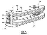
- the shock absorbers are integrally formed with the first cross member 42 ", the end portions 46" and 48 “of the first cross member 42” are formed by the superposition of elementary shock absorbers 80.
- the bumper increased performance in terms of energy dissipation, especially during 16 km / h impacts of the "Danner" type.
- the structure 40 "does not have vertical legs between the cross members 42" and 44, but has a third crossbar 43 ", arcuate, disposed in a horizontal plane, below the second crosspiece 44, and connecting the end portions 46 "and 48" of the first cross 42 ".
- the bumper 20 is mounted on the vehicle 2 by means of a support means allowing the movement of the bumper 20 between its upper position and its lower position, and vice versa.
- the moving means comprises guiding slides 90 allowing a translational movement of the bumper 20 with respect to the vehicle body. Such slides have the defect of being deformable, which may require their replacement following a shock.
- the displacement means comprises articulated linkages substantially in parallelogram allowing a translational or quasi-translational movement of the bumper 20 with respect to the vehicle body.
- Such an articulated linkage may for example form a deformable parallelogram, comprising, on each side of the vehicle body, two arms parallel to each other.
- Each arm has a first end pivotally mounted on the body structure, preferably on a plate fixed to the end of a chassis spar, and a second end pivotally mounted on the bumper.
- the bumper 20 has substantially the same orientation. In particular, in the open position, the bumper 20 still plays a role in protecting the rear of the vehicle.
- the bumper has, on its front face, locking means and / or holding means in position adapted to cooperate with the conjugate means which is provided with the body.
- the bumper can be opened only if the upper openings are. Therefore, the locking and holding means in position are advantageously simple: pin spring, handle ...
- the upper edge 26 of the movable bumper 20 protrudes above the loading threshold 16 and forms a sidewall to ensure that small objects placed on the floor 12 of the interior volume 4 do not do not slip out of the vehicle 2 while it is in motion and that its doors 22 and 24 are left open, for example because of the presence of an object of great length that does not fit fully into the interior volume 4.
- the movable bumper can form a step when placed in the open position.
- Those skilled in the art will know how to choose the appropriate materials allowing the mobile bumper to withstand the constraints associated with this use.
- the structure 40 of the movable bumper 20 makes it possible to distribute the forces: a fraction of the forces applied to the second crossmember 44, at its intermediate portion 60 or its arched arms 56 and 58, is transferred. to the first cross member 42 at the junction points between the first and second cross members 42 and 44; the other fraction of the applied forces is guided, by the legs 62, towards the intermediate portion 50 of the first crosspiece 42.
- the first crosspiece 42 then transmits the forces applied to it directly, or indirectly via the shock absorbers , at the body and side members of the vehicle chassis 2.
- the movable bumper according to the invention has a high height H compared to the bumpers fitted to commercial vehicles according to the prior art, while maximizing access to the interior volume.
- the lower edges of the openings are located in height, and do not descend to the floor level of the interior volume.
- the mobile bumper plays its role of energy dissipator. It is deformed and possibly broken.
- the lower parts of the openings are less likely to be affected during the same shock. This reduces the number of damaged parts and the related repair costs.
- the utility vehicle has two swinging doors
- the commercial vehicle has a single vertical axis door, or a tailgate type opening having a horizontal axis and a movable portion opening. to the top.
- This latter embodiment is particularly suitable for the case of a particular SUV vehicle such as MPV, minivan.
- the bumper according to the invention being in one piece, the number of parts is reduced. It therefore has a low cost of installation or replacement. It is of a simple structure ensuring a reduced manufacturing cost.
Abstract
Description
- La présente invention concerne un pare-chocs arrière pour véhicule automobile utilitaire ou particulier de tourisme. Dans ce qui suit, on désigne par véhicule automobile utilitaire, un véhicule présentant un volume arrière important, tel qu'un fourgon léger, un monospace, un SUV (« Sport Utility Vehicule » pour véhicule utilitaire de sport), un ludospace, un minispace, etc.
- Compte tenu, d'une part, des exigences de chargement du volume arrière, telles qu'un seuil de chargement abaissé, un plancher plat, etc., et, d'autre part, des exigences en vigueur sur la garde au sol d'un véhicule, les pare-chocs arrière connus des véhicules utilitaires possèdent une hauteur faible. En conséquence, ces pare-chocs connus présentent des performances réduites en matière de résistance aux chocs. De plus, la partie inférieure de ou des ouvrants arrière, qui descend jusqu'au niveau du seuil de chargement du volume intérieur, est souvent déformée en cas de choc. Cela entraîne des réparations importantes, de tôlerie et éventuellement de remplacement du système de fermeture des ouvrants, charnières et serrures.
- Le document
EP 1 162 116 A1 divulgue un pare-chocs d'un véhicule de tourisme, comportant un bloc central mobile entre : une position de fermeture, dans laquelle un bord supérieur du bloc central fait saillie verticalement au-dessus du seuil de chargement d'un volume arrière du véhicule, et est apte à coopérer avec au moins un ouvrant du véhicule pour fermer une ouverture d'accès au volume arrière ; et une position d'ouverture, dans laquelle le bord supérieur du bloc central est situé au niveau ou au-dessous du seuil de chargement pour permettre l'accès au volume arrière. Le bloc central comporte une coque extérieure, entourant une unique traverse intérieure métallique, rectiligne et en caisson, dont les extrémités sont en appui par l'intermédiaire d'amortisseurs de choc sur les longerons du véhicule. - De plus, seul le bloc central de ce pare-chocs est mobile. Ce pare-chocs comporte deux blocs latéraux fixes qui permettent au pare-chocs d'être conforme aux normes relatives aux chocs arrière et en particulier aux chocs à angle.
- Les moyens de déplacement du bloc central d'une position à l'autre, ainsi que la constitution du pare-chocs en plusieurs parties mobiles les unes par rapport aux autres, confèrent à ce pare-chocs une architecture complexe.
- En outre, les blocs latéraux fixes gênent l'accès au volume intérieur du véhicule et réduisent considérablement la dimension transversale du seuil de chargement.
- L'invention a donc pour but de proposer un pare-chocs arrière pour un véhicule automobile utilitaire, ayant une hauteur adaptée pour limiter le coût des réparations en cas de choc et permettant un accès le plus large possible au volume intérieur. L'invention a également pour but de proposer un pare-chocs arrière de fabrication et de montage simple.
- Pour cela l'invention porte sur un pare-chocs arrière pour véhicule automobile utilitaire monobloc et mobile entre une position de fermeture, dans laquelle un bord supérieur du pare-chocs fait saillie verticalement au-dessus d'un seuil de chargement d'un volume intérieur du véhicule, et est apte à coopérer avec au moins un ouvrant du véhicule pour fermer une ouverture d'accès au volume intérieur; et une position d'ouverture, dans laquelle le pare-chocs est entièrement situé au niveau ou au-dessous du seuil de chargement pour permettre l'accès au volume intérieur, le pare-chocs comportant un moyen de support permettant un déplacement du pare-chocs entre les positions par translation et/ou quasi translation selon une direction verticale.
- Suivant des modes particuliers de l'invention, le pare-chocs comporte une ou plusieurs des caractéristiques décrites dans les revendications 2 à 11.
- L'invention porte également sur un véhicule automobile utilitaire comportant un volume arrière, au moins un ouvrant et un pare-chocs tel que celui décrit précédemment, apte à coopérer avec l'ouvrant pour fermer une ouverture d'accès au volume intérieur, le bord inférieur de l'ouvrant étant situé à un niveau supérieur à celui du seuil de chargement du véhicule.
- L'invention et ses avantages seront mieux compris à la lecture de la description qui va suivre, donnée uniquement à titre d'exemple, et faite en se référant aux dessins annexés, dans lesquels :
- la
figure 1 est une vue en perspective arrière d'un véhicule automobile utilitaire, le pare-chocs arrière étant en position de fermeture ; - la
figure 2 est identique à lafigure 1 , le pare-chocs arrière étant en position d'ouverture ; - la
figure 3 est une représentation en perspective d'une première variante de réalisation de la structure du pare-chocs desfigures 1 et 2 ; - la
figure 4 est une représentation en perspective d'une seconde variante de réalisation de la structure du pare-chocs ; et, - la
figure 5 est une représentation en perspective d'une troisième variante de réalisation de la structure du pare-chocs. - Les
figures 1 et 2 représentent un véhicule automobile utilitaire 2 qui comporte un volume intérieur 4 arrière. Le volume intérieur 4 est délimité par un plafond 6, des parois droite 8 et gauche 10, et un plancher 12 essentiellement horizontal. - Le volume intérieur 4 est accessible par une ouverture arrière 14. Au niveau de l'ouverture 14, le plancher 12 présente un seuil de chargement 16 qui lui est coplanaire.
- Le véhicule 2 comporte, à l'arrière, un pare-chocs 20 mobile entre une position d'ouverture et une position de fermeture, ainsi qu'un ou plusieurs ouvrants supérieurs. Ces ouvrants supérieurs peuvent être constitués par deux portes battantes ou par un hayon, ce dernier étant monté pivotant autour d'une charnière verticale sur la paroi supérieure. Dans le cas ou ces ouvrants sont constitués de portes battantes, ils comporteront classiquement une porte droite 22 et une porte gauche 24. La porte droite 22, respectivement la porte gauche 24, est montée pivotante autour d'une charnière verticale sur la paroi droite 8, respectivement la paroi gauche 10, de la caisse du véhicule 2. Le bord inférieur 29, 30 des deux portes 22, 24 est situé à un niveau supérieur à celui du seuil de chargement 16.
- En variante, le véhicule comporte un unique ouvrant constitué par un hayon monté pivotant sur la paroi supérieure du coffre arrière du véhicule.
- Le pare-chocs 20 mobile est apte à être déplacé par translation, et/ou quasi-translation, selon une direction verticale, entre la position de fermeture, représentée à la
figure 1 , et la position d'ouverture, représentée à lafigure 2 . - Dans la position de fermeture, c'est-à-dire lorsque le pare-chocs 20 mobile se trouve dans sa position haute, le bord supérieur 26 du pare-chocs 20 mobile fait saillie verticalement au-dessus du seuil de chargement 16. Le bord supérieur 26 peut coopérer avec les bords inférieurs des portes droite 22 et gauche 24 pour fermer l'ouverture 14 d'accès au volume intérieur 4. Dans la position de fermeture, les bords latéraux droit 27 et gauche 28 du pare-chocs 20 sont affleurants aux parois latérales droite 8 et gauche 10 de la caisse du véhicule 2, tandis qu'un bord inférieur 25 du pare-chocs est affleurant à une paroi inférieure de la caisse du véhicule 2.
- Dans la position d'ouverture, c'est-à-dire lorsque le pare-chocs 20 mobile est dans sa position basse, le bord supérieur 26 du pare-chocs 20 est situé au-dessous, ou, en variante, au niveau, du seuil de chargement 16 du plancher 12. Ainsi le pare-chocs 20 ne gène pas le chargement d'objet dans le volume intérieur 4, l'ouverture 14 étant totalement dégagée. On notera que le seuil de chargement 16 s'étend sur la totalité de la largeur du volume intérieur 4.
- Le pare-chocs 20 mobile va maintenant être décrit plus en détail en référence à la
figure 3 . Le pare-chocs 20 mobile est monobloc et s'étend transversalement de la paroi latérale droite 8 à la paroi latérale gauche 10 du véhicule 2. - Le pare-chocs 20 mobile comporte une structure 40 permettant de répartir les forces générées lors d'un choc vers des bords périphériques du pare-chocs. Ces bords périphériques sont formés par les bords latéraux droit 27 et gauche 28 et le bord inférieur 25, et sont en appui sur des éléments de la caisse du véhicule 2. Ces éléments de la caisse du véhicule sont constitués, de préférence, par des surfaces verticales planes aptes à recevoir les bords périphériques du pare-chocs. Il s'agit, par exemple, de platines verticales étendues droite et gauche, reliant, d'un même côté de la caisse du véhicule, en voie haute, la face arrière d'extrémité d'un longeron, et, en voie basse, la face arrière d'une équerre, s'étendant verticalement vers le bas à partir de la face orientée vers le bas du longeron.
- La structure 40 est du type cage et est recouverte par au moins une peau extérieure.
- La structure 40, de forme générale en berceau, comporte une première traverse 42 conformée pour définir les bords latéraux droit 27 et gauche 28 et le bord inférieur 25 du pare-chocs 20. La structure 40 comporte une seconde traverse 44, conformée pour définir le bord supérieur 26 du pare-chocs 20.
- La première traverse 42 est de forme en U, dont les extrémités sont recourbées vers le haut. Cette traverse 42 comporte des premiers bras latéraux droit 46 et gauche 48, reliés par une première partie intermédiaire 50. En position montée sur le véhicule 2, et en position de fermeture du pare-chocs 20 mobile, la première traverse 42 se situe dans un plan vertical, parallèle à la direction transversale du véhicule 2. Chacun des premiers bras latéraux droit 46 et gauche 48 définit le bord latéral droit 27 ou gauche 28 du pare-chocs 20 et vient dans le prolongement de la paroi droite 8 ou gauche 10 de la caisse du véhicule 2. De manière similaire, la première partie intermédiaire 50 définit le bord inférieur 25 du pare-chocs 20 mobile.
- La seconde traverse 44 de la structure 40 est également de forme en U, dont les extrémités sont recourbées vers l'avant. Cette traverse 44 présente des seconds bras latéraux droit 56 et gauche 58, reliés par une portion intermédiaire 60. La seconde traverse 44 est conformée de manière à suivre le profil du bord supérieur 26 et par conséquent, des bords inférieurs 29 et 30 des portes droite 22 et gauche 24. En position montée sur le véhicule 2, et en position de fermeture du pare-chocs 20 mobile, la seconde traverse 44 se situe dans un plan horizontal et est située vers l'arrière par rapport au plan vertical de la première traverse 42. L'extrémité libre du premier bras latéral droit 46 est fixée, à angle droit, sur l'extrémité libre du second bras latéral droit 56. De manière similaire, l'extrémité libre du premier bras latéral gauche 48 est fixée sur l'extrémité libre du second bras latéral gauche 58.
- La structure 40 comporte une pluralité de jambages 62 de forme arquée. Chaque jambage 62, disposé verticalement en position montée du pare-chocs 20 sur le véhicule 2, relie la première partie intermédiaire 50 de la première traverse 42 à la seconde partie intermédiaire 60 de la seconde traverse 44.
- Les première et seconde traverses 42 et 44 et les jambages 62 sont réalisés en une matière plastique rigide. Les traverses sont avantageusement réalisées par injection d'un matériau en polymère thermoplastique (par exemple du polypropylène PP). Cette configuration est apte à dissiper intégralement l'énergie d'un choc de type « Danner », à participer à la réparabilité lors de chocs de moyenne intensité, mais aussi à protéger des occupants du véhicule, en particulier contre le « coup du lapin ». De préférence, les jambages 62 sont venus de matière avec les première et seconde traverses 42 et 44.
- En variante, les traverses sont en métal ou en un matériau hybride métal/polymère.
- La structure 40 ainsi formée est recouverte extérieurement par une peau extérieure 72, non représentée sur la
figure 3 pour plus de clarté, et éventuellement intérieurement par une peau intérieure 70. Les peaux intérieure 70 et extérieure 72 sont de préférence réalisées en un matériau plastique. - La structure comporte des moyens de fixation de la peau et d'accessoires équipant le pare-chocs. De préférence ces moyens de fixation sont venus de matière avec la structure. Ils sont conformés pour autoriser un montage et un démontage à volonté.
- Pour améliorer l'absorption d'énergie lors d'un choc arrière, le pare-chocs 20 mobile est muni d'un amortisseur de choc droit (non représenté) et d'un amortisseur de chocs gauche 74. Il s'agit de préférence d'un élément, à section transversale rectangulaire, apte à être compressé selon son épaisseur pour dissiper une fraction de l'énergie transmise lors d'un choc arrière.
- Dans une première variante de réalisation, l'amortisseur de chocs 74 est solidaire de la première traverse 42 et est positionné sur une face 75 de celle-ci. L'amortisseur de chocs 74 est constitué d'un profilé métallique, par exemple en aluminium, dont le volume intérieur est rempli d'une mousse apte à absorber de l'énergie lors de sa compression. En variante, l'amortisseur de chocs 74 est réalisé en un matériau en nid d'abeille d'aluminium ou d'un composite, en polymère injecté et caissonné, en mousse aluminium, ou en tout autre matériau économique susceptible d'absorber l'énergie d'un choc à basse ou moyenne vitesse. L'amortisseur de chocs 74 reprend la forme arquée du bras gauche 48 de la première traverse 42. L'amortisseur de chocs 74 comporte une portion supérieure 76 et une portion inférieure 78. Lorsque le pare-chocs 20 mobile est monté sur le véhicule 2 et est en position de fermeture, l'amortisseur de chocs 74 est situé entre la traverse 42 et le véhicule 2 : la portion supérieure 76 de l'amortisseur gauche 74 prend appui, du côté du véhicule 2, sur la paroi gauche 10, tandis que la portion inférieure 78 prend appui, du côté du véhicule 2, sur un longeron du châssis du véhicule 2. Une description similaire pourrait être faite au sujet de l'amortisseur de chocs droit.
- Dans une seconde variante de réalisation illustrée à la
figure 4 , la première traverse 42' comporte sur sa face antérieure un logement creux 75 destiné à recevoir un amortisseur de chocs 74' d'épaisseur adaptée. - Dans une troisième variante de réalisation illustrée à la
figure 5 , les amortisseurs de chocs sont venus de matière avec la première traverse 42". Les portions d'extrémité 46" et 48" de la première traverse 42" sont formées par la superposition d'amortisseurs de chocs élémentaires 80. Le pare-chocs présente des performances accrues en termes de dissipation d'énergie, notamment lors de chocs 16 km/h du type « Danner ». On notera que selon cette troisième variante de réalisation, la structure 40" ne comporte pas de jambages verticaux entre les traverses 42" et 44, mais présente une troisième traverse 43", de forme arquée, disposée dans un plan horizontal, au-dessous de la seconde traverse 44, et reliant les portions d'extrémité 46" et 48" de la premières traverse 42". - Le pare-chocs 20 est monté sur le véhicule 2 par l'intermédiaire d'un moyen de support permettant le mouvement du pare-chocs 20 entre sa position haute et sa position basse, et inversement. Le moyen de déplacement comporte des glissières de guidage 90 permettant un mouvement de translation du pare-chocs 20 par rapport à la caisse du véhicule. De telles glissières présentent le défaut d'être déformables, ce qui peut nécessiter leur remplacement à la suite d'un choc.
- En variante, le moyen de déplacement comporte des tringleries articulées sensiblement en parallélogramme permettant un mouvement de translation ou de quasi-translation du pare-chocs 20 par rapport à la caisse du véhicule.
- Une telle tringlerie articulée peut par exemple former un parallélogramme déformable, comportant, de chaque côté de la caisse du véhicule, deux bras parallèles entre eux. Chaque bras comporte une première extrémité montée pivotante sur la structure de caisse, de préférence sur une platine fixée à l'extrémité d'un longeron du châssis, et une seconde extrémité montée pivotante sur le pare-chocs.
- Selon ce mode de réalisation, à tout moment de son utilisation, le pare-chocs 20 présente sensiblement la même orientation. En particulier, en position d'ouverture, le pare-chocs 20 joue encore un rôle de protection de l'arrière du véhicule.
- Le pare-chocs présente, sur sa face avant, des moyens de verrouillage et/ou des moyens de maintien en position aptes à coopérer avec des moyens conjugués dont est munie la carrosserie.
- De préférence le pare-chocs ne peut être ouvert que si les ouvrants supérieurs le sont. De ce fait, les moyens de verrouillage et de maintien en position sont avantageusement simples : goupille à ressort, poignée...
- On notera qu'en position de fermeture, le bord supérieur 26 du pare-chocs 20 mobile fait saillie au-dessus du seuil de chargement 16 et forme une ridelle permettant de garantir que des petits objets posés sur le plancher 12 du volume intérieur 4 ne glissent pas hors du véhicule 2 alors qu'il est en mouvement et que ses portes 22 et 24 sont laissées ouvertes, à cause par exemple de la présence d'un objet de grande longueur qui ne rentre pas intégralement dans le volume intérieur 4.
- Le pare-chocs mobile peut former un marchepied lorsqu'il est placé en position d'ouverture. L'homme du métier saura comment choisir les matériaux adaptés permettant au pare-chocs mobile de supporter les contraintes liées à cette utilisation.
- En cas de choc arrière, la structure 40 du pare-chocs 20 mobile permet de répartir les efforts : une fraction des forces appliquées à la seconde traverse 44, au niveau de sa partie intermédiaire 60 ou des ses bras 56 et 58 arqués, est transférée vers la première traverse 42 au niveau des points de jonction entre les première et seconde traverses 42 et 44 ; l'autre fraction des forces appliquées est guidée, par les jambages 62, vers la partie intermédiaire 50 de la première traverse 42. La première traverse 42 transmet ensuite les forces qui lui sont appliquées directement, ou indirectement par l'intermédiaire des amortisseurs de choc, à la caisse et aux longerons du châssis du véhicule 2.
- Le pare-chocs mobile selon l'invention présente une hauteur H importante par rapport aux pare-chocs équipant les véhicules utilitaires selon l'art antérieur, tout en maximisant l'accès au volume intérieur. Les bords inférieurs des ouvrants sont situés en hauteur, et ne descendent pas jusqu'au niveau du plancher du volume intérieur. Ainsi, en cas de choc, le pare-chocs mobile joue son rôle de dissipateur d'énergie. Il est déformé et éventuellement brisé. En revanche, les parties inférieures des ouvrants présentent moins de risque d'être touchées durant ce même choc. On réduit d'autant le nombre des pièces abîmées et les coûts de réparation afférents.
- Alors que dans le mode de réalisation décrit, le véhicule utilitaire comporte deux portes battantes, il est parfaitement possible que le véhicule utilitaire comporte une porte unique à axe vertical, ou un ouvrant de type hayon ayant un axe horizontal et une partie mobile s'ouvrant vers le haut. Ce dernier mode de réalisation est particulièrement approprié au cas d'un véhicule particulier SUV tel que ludospace, monospace.
- Avantageusement, le pare-chocs selon l'invention étant monobloc, le nombre de pièces est réduit. Il présente donc un coût d'installation ou de remplacement faible. Il est d'une structure simple lui assurant un coût de fabrication réduit.
- L'homme du métier comprendra que la structure venant d'être décrite permet une absorption satisfaisante des chocs tout en présentant un nombre réduit d'éléments, et pouvant être obtenu à faible coût.
Claims (12)
- Pare-chocs arrière pour véhicule automobile utilitaire (2), caractérisé en ce qu'il est monobloc et est mobile entre :- une position de fermeture, dans laquelle un bord supérieur (26) du pare-chocs (20) fait saillie verticalement au-dessus d'un seuil de chargement (16) d'un volume intérieur (4) du véhicule, et est apte à coopérer avec au moins un ouvrant (22, 24) du véhicule pour fermer une ouverture (14) d'accès au volume intérieur; et,- une position d'ouverture, dans laquelle le pare-chocs est entièrement situé au niveau ou au-dessous du seuil de chargement pour permettre l'accès au volume intérieur,le pare-chocs comportant un moyen de support (90) permettant un déplacement du pare-chocs entre lesdites positions par translation et/ou quasi translation selon une direction verticale.
- Pare-chocs selon la revendication 1, caractérisé en ce qu'il s'étend transversalement de la paroi latérale droite à la paroi latérale gauche du véhicule.
- Pare-chocs selon la revendication 1 ou la revendication 2, caractérisé en ce qu'il comporte une structure (40, 40', 40") apte à répartir les forces générées lors d'un choc arrière vers une surface d'appui du pare-chocs (20) sur le véhicule (2), la surface d'appui étant située sur un bord latéral (27, 28) ou inférieur (25) du pare-chocs.
- Pare-chocs selon la revendication 3, caractérisé en ce que la structure (40, 40', 40") est réalisée en une matière plastique rigide.
- Pare-chocs selon la revendication 3 ou la revendication 4, caractérisé en ce que la structure (40, 40', 40") comporte :- une première traverse (42, 42', 42") à extrémités relevées, conformée pour définir les bords inférieur (25) et latéraux (27, 28) du pare-chocs (20) ; et- une seconde traverse (44), conformée pour définir le bord supérieur (26) du pare-chocs ;
- Pare-chocs selon la revendication 5, caractérisé en ce que la structure est du type cage et comporte une pluralité de jambages (62) reliant les première et seconde traverses entre elles.
- Pare-chocs selon la revendication 6, caractérisé en ce que la seconde traverse (44) comporte des extrémités latérales recourbées vers l'avant, et en ce que les jambages (62) ont une extrémité inférieure recourbée vers l'avant.
- Pare-chocs selon la revendication 6 ou la revendication 7, caractérisé en ce que les jambages (62) sont venus de matière avec les première et seconde traverses.
- Pare-chocs selon l'une quelconque des revendications 3 à 8, caractérisé en ce que la structure (40, 40', 40") est recouverte par une peau (70, 72).
- Pare-chocs selon l'une quelconque des revendications 3 à 9, caractérisé en ce qu'il comporte au moins un amortisseur de choc, définissant la surface d'appui du pare-chocs sur le véhicule (2).
- Pare-chocs selon la revendication 10, caractérisé en ce que l'amortisseur de choc est venu de matière avec la structure (40").
- Véhicule automobile utilitaire comportant un volume arrière, au moins un ouvrant et un pare-chocs, caractérisé en ce que le pare-chocs est un pare-chocs (20) selon l'une quelconque des revendications 1 à 11, apte à coopérer avec l'ouvrant (22, 24) pour fermer une ouverture (14) d'accès au volume intérieur (4), le bord inférieur (29, 30) de l'ouvrant (22, 24) étant situé à un niveau supérieur à celui du seuil de chargement (16) du véhicule (2).
Applications Claiming Priority (1)
| Application Number | Priority Date | Filing Date | Title |
|---|---|---|---|
| FR0854021A FR2932739B1 (fr) | 2008-06-18 | 2008-06-18 | Pare-chocs arriere pour vehicule automobile utilitaire |
Publications (2)
| Publication Number | Publication Date |
|---|---|
| EP2135778A1 true EP2135778A1 (fr) | 2009-12-23 |
| EP2135778B1 EP2135778B1 (fr) | 2011-12-14 |
Family
ID=40351876
Family Applications (2)
| Application Number | Title | Priority Date | Filing Date |
|---|---|---|---|
| EP09163019A Not-in-force EP2135778B1 (fr) | 2008-06-18 | 2009-06-17 | Pare-chocs arrière pour véhicule automobile utilitaire |
| EP09163018A Not-in-force EP2135776B1 (fr) | 2008-06-18 | 2009-06-17 | Pare-chocs arrière pour véhicule automobile utilitaire |
Family Applications After (1)
| Application Number | Title | Priority Date | Filing Date |
|---|---|---|---|
| EP09163018A Not-in-force EP2135776B1 (fr) | 2008-06-18 | 2009-06-17 | Pare-chocs arrière pour véhicule automobile utilitaire |
Country Status (5)
| Country | Link |
|---|---|
| EP (2) | EP2135778B1 (fr) |
| AT (2) | ATE537038T1 (fr) |
| ES (2) | ES2377279T3 (fr) |
| FR (1) | FR2932739B1 (fr) |
| PL (1) | PL2135776T3 (fr) |
Cited By (2)
| Publication number | Priority date | Publication date | Assignee | Title |
|---|---|---|---|---|
| WO2018220305A1 (fr) | 2017-05-31 | 2018-12-06 | Psa Automobiles Sa | Dispositif d'entretoisement pour appui de roue de vehicule en choc arriere et vehicule presentant un tel dispositif |
| WO2020187858A1 (fr) | 2019-03-15 | 2020-09-24 | Timson Andrew | Appareil de protection de hayon élévateur de véhicule |
Families Citing this family (5)
| Publication number | Priority date | Publication date | Assignee | Title |
|---|---|---|---|---|
| FR2952874B1 (fr) * | 2009-11-20 | 2013-11-29 | Faurecia Bloc Avant | Bouclier pare-chocs pour vehicule automobile |
| FR2959707B1 (fr) | 2010-05-05 | 2013-03-15 | Faurecia Bloc Avant | Element de face arriere et face arriere pour vehicule automobile |
| FR2980145B1 (fr) * | 2011-09-16 | 2013-11-29 | Faurecia Bloc Avant | Poutre de pare-chocs, ensemble pare-chocs et vehicule equipes d'une telle poutre de pare-chocs |
| JP5850037B2 (ja) * | 2013-12-24 | 2016-02-03 | トヨタ自動車株式会社 | 車体の衝撃吸収構造 |
| FR3122137A1 (fr) * | 2021-04-26 | 2022-10-28 | Psa Automobiles Sa | Dispositif de marchepied à déformation programmée. |
Citations (4)
| Publication number | Priority date | Publication date | Assignee | Title |
|---|---|---|---|---|
| US3533654A (en) * | 1968-01-30 | 1970-10-13 | Harold A Kannegieter | Shiftable bumper |
| EP0745516A1 (fr) * | 1995-05-31 | 1996-12-04 | FIAT AUTO S.p.A. | Pare-choc s'abaissant pour véhicules à moteur, en particulier pour automobiles |
| EP1162116A2 (fr) | 2000-06-09 | 2001-12-12 | ITALDESIGN-GIUGIARO S.p.A | Pare-chocs arrière abaissable de véhicule |
| EP1470966A1 (fr) * | 2003-03-31 | 2004-10-27 | Mazda Motor Corporation | Structure de pare-chocs arrière et véhicule muni d'une telle structure |
Family Cites Families (4)
| Publication number | Priority date | Publication date | Assignee | Title |
|---|---|---|---|---|
| DE19956561A1 (de) * | 1999-11-24 | 2001-05-31 | Benteler Werke Ag | Stoßfängeranordnung |
| FR2829733B1 (fr) * | 2001-09-14 | 2003-11-28 | Plastic Omnium Cie | Systeme d'absorption d'energie pour vehicule automobile |
| FR2847214B1 (fr) * | 2002-11-15 | 2005-03-18 | Plastic Omnium Cie | Appui bas pour chocs pieton de vehicule automobile et pare-chocs de vehicule automobile muni d'un tel appui bas |
| DE202007001369U1 (de) * | 2007-01-25 | 2008-05-29 | Wagon Automotive Gmbh | Aufprallquerträger für eine Kraftfahrzeugkarosserie |
-
2008
- 2008-06-18 FR FR0854021A patent/FR2932739B1/fr not_active Expired - Fee Related
-
2009
- 2009-06-17 ES ES09163018T patent/ES2377279T3/es active Active
- 2009-06-17 AT AT09163019T patent/ATE537038T1/de active
- 2009-06-17 EP EP09163019A patent/EP2135778B1/fr not_active Not-in-force
- 2009-06-17 EP EP09163018A patent/EP2135776B1/fr not_active Not-in-force
- 2009-06-17 ES ES09163019T patent/ES2377176T3/es active Active
- 2009-06-17 AT AT09163018T patent/ATE537036T1/de active
- 2009-06-17 PL PL09163018T patent/PL2135776T3/pl unknown
Patent Citations (4)
| Publication number | Priority date | Publication date | Assignee | Title |
|---|---|---|---|---|
| US3533654A (en) * | 1968-01-30 | 1970-10-13 | Harold A Kannegieter | Shiftable bumper |
| EP0745516A1 (fr) * | 1995-05-31 | 1996-12-04 | FIAT AUTO S.p.A. | Pare-choc s'abaissant pour véhicules à moteur, en particulier pour automobiles |
| EP1162116A2 (fr) | 2000-06-09 | 2001-12-12 | ITALDESIGN-GIUGIARO S.p.A | Pare-chocs arrière abaissable de véhicule |
| EP1470966A1 (fr) * | 2003-03-31 | 2004-10-27 | Mazda Motor Corporation | Structure de pare-chocs arrière et véhicule muni d'une telle structure |
Cited By (2)
| Publication number | Priority date | Publication date | Assignee | Title |
|---|---|---|---|---|
| WO2018220305A1 (fr) | 2017-05-31 | 2018-12-06 | Psa Automobiles Sa | Dispositif d'entretoisement pour appui de roue de vehicule en choc arriere et vehicule presentant un tel dispositif |
| WO2020187858A1 (fr) | 2019-03-15 | 2020-09-24 | Timson Andrew | Appareil de protection de hayon élévateur de véhicule |
Also Published As
| Publication number | Publication date |
|---|---|
| PL2135776T3 (pl) | 2012-05-31 |
| ATE537036T1 (de) | 2011-12-15 |
| FR2932739A1 (fr) | 2009-12-25 |
| EP2135776A1 (fr) | 2009-12-23 |
| ATE537038T1 (de) | 2011-12-15 |
| EP2135778B1 (fr) | 2011-12-14 |
| FR2932739B1 (fr) | 2010-09-03 |
| EP2135776B1 (fr) | 2011-12-14 |
| ES2377176T3 (es) | 2012-03-23 |
| ES2377279T3 (es) | 2012-03-26 |
Similar Documents
| Publication | Publication Date | Title |
|---|---|---|
| EP2135778B1 (fr) | Pare-chocs arrière pour véhicule automobile utilitaire | |
| EP2233367B1 (fr) | Module de face avant de véhicule automobile comprenant un cadre structurel et un bouclier | |
| EP2322386B1 (fr) | Ensemble avant de véhicule automobile comprenant un bouclier pare-chocs avant portant des moyens de fixation d'au moins un équipement auxiliaire du véhicule automobile | |
| EP2384938B1 (fr) | Face arrière pour véhicule automobile | |
| EP2233368B1 (fr) | Ensemble avant de véhicule automobile comprenant un bouclier pare-chocs avant | |
| FR2955077A1 (fr) | Vehicule dote d'un plancher apte a recevoir une batterie et une poutre de renforcement | |
| FR3051416B1 (fr) | Dispositif de separation entre un habitacle et un espace de chargement et vehicule equipe d'un tel dispositif | |
| EP1878621B1 (fr) | Pare-chocs de vehicule automobile, notamment pour vehicule de type break | |
| EP1334882A1 (fr) | Piéce de poutre de pare-choc pour véhicule comportant deux absorbeurs de chocs et un barreau | |
| EP1473197B1 (fr) | Pare-chocs de véhicule automobile pourvu d'éléments d'absorption de choc, et véhicule automobile équipé d'un tel pare-chocs | |
| FR3063699A1 (fr) | Agencement de maintien d'un bac de coffre a l'avant d'une structure de caisse d'un vehicule automobile. | |
| FR2920727A1 (fr) | Pare-chocs comprenant une bordure inferieure et une grille d'entree d'air | |
| EP3677463B1 (fr) | Guide d'air d'une face avant d'un vehicule automobile | |
| EP2867097A1 (fr) | Véhicule automobile comprenant une partie de renfort supplémentaire capable de guider la déformation de la structure de pilier central en cas de choc latéral | |
| EP1916134B1 (fr) | Ouvrant arrière de véhicule automobile | |
| EP2325070B1 (fr) | Ensemble avant de véhicule automobile comprenant un bouclier pare-chocs avant pourvu d'une poutre permettant la fixation d'au moins un équipement auxiliaire du véhicule automobile | |
| EP2135797B1 (fr) | Module de face avant pour un véhicule automobile. | |
| WO2013140053A1 (fr) | Vehicule automobile equipe d'un dispositif de securite a traverse articulee contre les chocs de bagages | |
| FR2986193A1 (fr) | Dispositif de protection pour glissiere de siege de vehicule automobile | |
| EP3385150B1 (fr) | Renforcement de plancher de véhicule en cas de choc frontal à faible recouvrement | |
| EP1378425B1 (fr) | Système de portillon pour plateau arrière de véhicule automobile | |
| FR2989038A1 (fr) | Siege modulable de vehicule |
Legal Events
| Date | Code | Title | Description |
|---|---|---|---|
| PUAI | Public reference made under article 153(3) epc to a published international application that has entered the european phase |
Free format text: ORIGINAL CODE: 0009012 |
|
| AK | Designated contracting states |
Kind code of ref document: A1 Designated state(s): AT BE BG CH CY CZ DE DK EE ES FI FR GB GR HR HU IE IS IT LI LT LU LV MC MK MT NL NO PL PT RO SE SI SK TR |
|
| 17P | Request for examination filed |
Effective date: 20100519 |
|
| 17Q | First examination report despatched |
Effective date: 20100630 |
|
| GRAP | Despatch of communication of intention to grant a patent |
Free format text: ORIGINAL CODE: EPIDOSNIGR1 |
|
| GRAS | Grant fee paid |
Free format text: ORIGINAL CODE: EPIDOSNIGR3 |
|
| GRAA | (expected) grant |
Free format text: ORIGINAL CODE: 0009210 |
|
| AK | Designated contracting states |
Kind code of ref document: B1 Designated state(s): AT BE BG CH CY CZ DE DK EE ES FI FR GB GR HR HU IE IS IT LI LT LU LV MC MK MT NL NO PL PT RO SE SI SK TR |
|
| REG | Reference to a national code |
Ref country code: GB Ref legal event code: FG4D Free format text: NOT ENGLISH |
|
| REG | Reference to a national code |
Ref country code: CH Ref legal event code: EP |
|
| REG | Reference to a national code |
Ref country code: IE Ref legal event code: FG4D |
|
| REG | Reference to a national code |
Ref country code: DE Ref legal event code: R096 Ref document number: 602009004146 Country of ref document: DE Effective date: 20120301 |
|
| REG | Reference to a national code |
Ref country code: ES Ref legal event code: FG2A Ref document number: 2377176 Country of ref document: ES Kind code of ref document: T3 Effective date: 20120323 |
|
| REG | Reference to a national code |
Ref country code: NL Ref legal event code: VDEP Effective date: 20111214 |
|
| PG25 | Lapsed in a contracting state [announced via postgrant information from national office to epo] |
Ref country code: NO Free format text: LAPSE BECAUSE OF FAILURE TO SUBMIT A TRANSLATION OF THE DESCRIPTION OR TO PAY THE FEE WITHIN THE PRESCRIBED TIME-LIMIT Effective date: 20120314 Ref country code: LT Free format text: LAPSE BECAUSE OF FAILURE TO SUBMIT A TRANSLATION OF THE DESCRIPTION OR TO PAY THE FEE WITHIN THE PRESCRIBED TIME-LIMIT Effective date: 20111214 |
|
| LTIE | Lt: invalidation of european patent or patent extension |
Effective date: 20111214 |
|
| PG25 | Lapsed in a contracting state [announced via postgrant information from national office to epo] |
Ref country code: HR Free format text: LAPSE BECAUSE OF FAILURE TO SUBMIT A TRANSLATION OF THE DESCRIPTION OR TO PAY THE FEE WITHIN THE PRESCRIBED TIME-LIMIT Effective date: 20111214 Ref country code: NL Free format text: LAPSE BECAUSE OF FAILURE TO SUBMIT A TRANSLATION OF THE DESCRIPTION OR TO PAY THE FEE WITHIN THE PRESCRIBED TIME-LIMIT Effective date: 20111214 Ref country code: SE Free format text: LAPSE BECAUSE OF FAILURE TO SUBMIT A TRANSLATION OF THE DESCRIPTION OR TO PAY THE FEE WITHIN THE PRESCRIBED TIME-LIMIT Effective date: 20111214 Ref country code: LV Free format text: LAPSE BECAUSE OF FAILURE TO SUBMIT A TRANSLATION OF THE DESCRIPTION OR TO PAY THE FEE WITHIN THE PRESCRIBED TIME-LIMIT Effective date: 20111214 Ref country code: SI Free format text: LAPSE BECAUSE OF FAILURE TO SUBMIT A TRANSLATION OF THE DESCRIPTION OR TO PAY THE FEE WITHIN THE PRESCRIBED TIME-LIMIT Effective date: 20111214 Ref country code: GR Free format text: LAPSE BECAUSE OF FAILURE TO SUBMIT A TRANSLATION OF THE DESCRIPTION OR TO PAY THE FEE WITHIN THE PRESCRIBED TIME-LIMIT Effective date: 20120315 |
|
| PG25 | Lapsed in a contracting state [announced via postgrant information from national office to epo] |
Ref country code: CY Free format text: LAPSE BECAUSE OF FAILURE TO SUBMIT A TRANSLATION OF THE DESCRIPTION OR TO PAY THE FEE WITHIN THE PRESCRIBED TIME-LIMIT Effective date: 20111214 |
|
| REG | Reference to a national code |
Ref country code: IE Ref legal event code: FD4D |
|
| PG25 | Lapsed in a contracting state [announced via postgrant information from national office to epo] |
Ref country code: IS Free format text: LAPSE BECAUSE OF FAILURE TO SUBMIT A TRANSLATION OF THE DESCRIPTION OR TO PAY THE FEE WITHIN THE PRESCRIBED TIME-LIMIT Effective date: 20120414 Ref country code: EE Free format text: LAPSE BECAUSE OF FAILURE TO SUBMIT A TRANSLATION OF THE DESCRIPTION OR TO PAY THE FEE WITHIN THE PRESCRIBED TIME-LIMIT Effective date: 20111214 Ref country code: IE Free format text: LAPSE BECAUSE OF FAILURE TO SUBMIT A TRANSLATION OF THE DESCRIPTION OR TO PAY THE FEE WITHIN THE PRESCRIBED TIME-LIMIT Effective date: 20111214 Ref country code: CZ Free format text: LAPSE BECAUSE OF FAILURE TO SUBMIT A TRANSLATION OF THE DESCRIPTION OR TO PAY THE FEE WITHIN THE PRESCRIBED TIME-LIMIT Effective date: 20111214 Ref country code: BG Free format text: LAPSE BECAUSE OF FAILURE TO SUBMIT A TRANSLATION OF THE DESCRIPTION OR TO PAY THE FEE WITHIN THE PRESCRIBED TIME-LIMIT Effective date: 20120314 Ref country code: SK Free format text: LAPSE BECAUSE OF FAILURE TO SUBMIT A TRANSLATION OF THE DESCRIPTION OR TO PAY THE FEE WITHIN THE PRESCRIBED TIME-LIMIT Effective date: 20111214 |
|
| PG25 | Lapsed in a contracting state [announced via postgrant information from national office to epo] |
Ref country code: PT Free format text: LAPSE BECAUSE OF FAILURE TO SUBMIT A TRANSLATION OF THE DESCRIPTION OR TO PAY THE FEE WITHIN THE PRESCRIBED TIME-LIMIT Effective date: 20120416 Ref country code: PL Free format text: LAPSE BECAUSE OF FAILURE TO SUBMIT A TRANSLATION OF THE DESCRIPTION OR TO PAY THE FEE WITHIN THE PRESCRIBED TIME-LIMIT Effective date: 20111214 Ref country code: RO Free format text: LAPSE BECAUSE OF FAILURE TO SUBMIT A TRANSLATION OF THE DESCRIPTION OR TO PAY THE FEE WITHIN THE PRESCRIBED TIME-LIMIT Effective date: 20111214 |
|
| REG | Reference to a national code |
Ref country code: AT Ref legal event code: MK05 Ref document number: 537038 Country of ref document: AT Kind code of ref document: T Effective date: 20111214 |
|
| PLBE | No opposition filed within time limit |
Free format text: ORIGINAL CODE: 0009261 |
|
| STAA | Information on the status of an ep patent application or granted ep patent |
Free format text: STATUS: NO OPPOSITION FILED WITHIN TIME LIMIT |
|
| PG25 | Lapsed in a contracting state [announced via postgrant information from national office to epo] |
Ref country code: DK Free format text: LAPSE BECAUSE OF FAILURE TO SUBMIT A TRANSLATION OF THE DESCRIPTION OR TO PAY THE FEE WITHIN THE PRESCRIBED TIME-LIMIT Effective date: 20111214 |
|
| 26N | No opposition filed |
Effective date: 20120917 |
|
| PG25 | Lapsed in a contracting state [announced via postgrant information from national office to epo] |
Ref country code: IT Free format text: LAPSE BECAUSE OF FAILURE TO SUBMIT A TRANSLATION OF THE DESCRIPTION OR TO PAY THE FEE WITHIN THE PRESCRIBED TIME-LIMIT Effective date: 20111214 |
|
| BERE | Be: lapsed |
Owner name: FAURECIA BLOC AVANT Effective date: 20120630 |
|
| REG | Reference to a national code |
Ref country code: DE Ref legal event code: R097 Ref document number: 602009004146 Country of ref document: DE Effective date: 20120917 |
|
| PG25 | Lapsed in a contracting state [announced via postgrant information from national office to epo] |
Ref country code: AT Free format text: LAPSE BECAUSE OF FAILURE TO SUBMIT A TRANSLATION OF THE DESCRIPTION OR TO PAY THE FEE WITHIN THE PRESCRIBED TIME-LIMIT Effective date: 20111214 Ref country code: MC Free format text: LAPSE BECAUSE OF NON-PAYMENT OF DUE FEES Effective date: 20120630 |
|
| PG25 | Lapsed in a contracting state [announced via postgrant information from national office to epo] |
Ref country code: MK Free format text: LAPSE BECAUSE OF FAILURE TO SUBMIT A TRANSLATION OF THE DESCRIPTION OR TO PAY THE FEE WITHIN THE PRESCRIBED TIME-LIMIT Effective date: 20111214 |
|
| PG25 | Lapsed in a contracting state [announced via postgrant information from national office to epo] |
Ref country code: BE Free format text: LAPSE BECAUSE OF NON-PAYMENT OF DUE FEES Effective date: 20120630 |
|
| PG25 | Lapsed in a contracting state [announced via postgrant information from national office to epo] |
Ref country code: FI Free format text: LAPSE BECAUSE OF FAILURE TO SUBMIT A TRANSLATION OF THE DESCRIPTION OR TO PAY THE FEE WITHIN THE PRESCRIBED TIME-LIMIT Effective date: 20111214 |
|
| PG25 | Lapsed in a contracting state [announced via postgrant information from national office to epo] |
Ref country code: MT Free format text: LAPSE BECAUSE OF FAILURE TO SUBMIT A TRANSLATION OF THE DESCRIPTION OR TO PAY THE FEE WITHIN THE PRESCRIBED TIME-LIMIT Effective date: 20111214 |
|
| REG | Reference to a national code |
Ref country code: CH Ref legal event code: PL |
|
| GBPC | Gb: european patent ceased through non-payment of renewal fee |
Effective date: 20130617 |
|
| PG25 | Lapsed in a contracting state [announced via postgrant information from national office to epo] |
Ref country code: LI Free format text: LAPSE BECAUSE OF NON-PAYMENT OF DUE FEES Effective date: 20130630 Ref country code: TR Free format text: LAPSE BECAUSE OF FAILURE TO SUBMIT A TRANSLATION OF THE DESCRIPTION OR TO PAY THE FEE WITHIN THE PRESCRIBED TIME-LIMIT Effective date: 20111214 Ref country code: GB Free format text: LAPSE BECAUSE OF NON-PAYMENT OF DUE FEES Effective date: 20130617 Ref country code: CH Free format text: LAPSE BECAUSE OF NON-PAYMENT OF DUE FEES Effective date: 20130630 |
|
| PG25 | Lapsed in a contracting state [announced via postgrant information from national office to epo] |
Ref country code: LU Free format text: LAPSE BECAUSE OF NON-PAYMENT OF DUE FEES Effective date: 20120617 |
|
| PG25 | Lapsed in a contracting state [announced via postgrant information from national office to epo] |
Ref country code: HU Free format text: LAPSE BECAUSE OF FAILURE TO SUBMIT A TRANSLATION OF THE DESCRIPTION OR TO PAY THE FEE WITHIN THE PRESCRIBED TIME-LIMIT Effective date: 20090617 |
|
| REG | Reference to a national code |
Ref country code: FR Ref legal event code: PLFP Year of fee payment: 8 |
|
| REG | Reference to a national code |
Ref country code: FR Ref legal event code: PLFP Year of fee payment: 9 |
|
| PGFP | Annual fee paid to national office [announced via postgrant information from national office to epo] |
Ref country code: FR Payment date: 20170523 Year of fee payment: 9 Ref country code: DE Payment date: 20170522 Year of fee payment: 9 |
|
| PGFP | Annual fee paid to national office [announced via postgrant information from national office to epo] |
Ref country code: ES Payment date: 20170703 Year of fee payment: 9 |
|
| REG | Reference to a national code |
Ref country code: DE Ref legal event code: R119 Ref document number: 602009004146 Country of ref document: DE |
|
| PG25 | Lapsed in a contracting state [announced via postgrant information from national office to epo] |
Ref country code: DE Free format text: LAPSE BECAUSE OF NON-PAYMENT OF DUE FEES Effective date: 20190101 Ref country code: FR Free format text: LAPSE BECAUSE OF NON-PAYMENT OF DUE FEES Effective date: 20180630 |
|
| REG | Reference to a national code |
Ref country code: ES Ref legal event code: FD2A Effective date: 20190916 |
|
| PG25 | Lapsed in a contracting state [announced via postgrant information from national office to epo] |
Ref country code: ES Free format text: LAPSE BECAUSE OF NON-PAYMENT OF DUE FEES Effective date: 20180618 |