EP2135663A2 - Wet scrubber tray - Google Patents
Wet scrubber tray Download PDFInfo
- Publication number
- EP2135663A2 EP2135663A2 EP09162862A EP09162862A EP2135663A2 EP 2135663 A2 EP2135663 A2 EP 2135663A2 EP 09162862 A EP09162862 A EP 09162862A EP 09162862 A EP09162862 A EP 09162862A EP 2135663 A2 EP2135663 A2 EP 2135663A2
- Authority
- EP
- European Patent Office
- Prior art keywords
- tray
- stiffeners
- trays
- perforated
- wet scrubber
- Prior art date
- Legal status (The legal status is an assumption and is not a legal conclusion. Google has not performed a legal analysis and makes no representation as to the accuracy of the status listed.)
- Granted
Links
Images


Classifications
-
- B—PERFORMING OPERATIONS; TRANSPORTING
- B01—PHYSICAL OR CHEMICAL PROCESSES OR APPARATUS IN GENERAL
- B01D—SEPARATION
- B01D3/00—Distillation or related exchange processes in which liquids are contacted with gaseous media, e.g. stripping
- B01D3/14—Fractional distillation or use of a fractionation or rectification column
- B01D3/32—Other features of fractionating columns ; Constructional details of fractionating columns not provided for in groups B01D3/16 - B01D3/30
- B01D3/324—Tray constructions
- B01D3/326—Tray supports
-
- B—PERFORMING OPERATIONS; TRANSPORTING
- B01—PHYSICAL OR CHEMICAL PROCESSES OR APPARATUS IN GENERAL
- B01D—SEPARATION
- B01D53/00—Separation of gases or vapours; Recovering vapours of volatile solvents from gases; Chemical or biological purification of waste gases, e.g. engine exhaust gases, smoke, fumes, flue gases, aerosols
- B01D53/34—Chemical or biological purification of waste gases
- B01D53/74—General processes for purification of waste gases; Apparatus or devices specially adapted therefor
- B01D53/77—Liquid phase processes
- B01D53/78—Liquid phase processes with gas-liquid contact
Definitions
- the present invention relates to methods and apparatus for obtaining counter-current gas-liquid contact, such as wet scrubbers which involve gas-liquid contact between flue gas containing sulfur oxides and a slurry or solution containing reactive materials as a chemical reacting absorbing medium. More particularly, but not exclusively, the present invention is drawn to an improved wet scrubber tray construction and a gas-liquid contact apparatus employing same.
- wet scrubber gas-liquid contact systems used for the removal of sulfur oxides (SO x ) from flue gases produced from the combustion of fossil fuels are known. See for example US Patent No. 4,263,021 to Downs et al ., the text of which is hereby incorporated by reference as though fully set forth herein. Additional details of wet scrubber systems for SO x removal are provided in Chapter 35 of Steam/its generation and use, 41st Edition, Kitto and Stultz, Eds., Copyright ⁇ 2005, The Babcock & Wilcox Company , the text of which is hereby incorporated by reference as though fully set forth herein. Such systems are also referred to as wet flue gas desulfurization (WFGD) systems.
- WFGD wet flue gas desulfurization
- Figs. 1 and 2 illustrate components of one type of known wet scrubber system, generally designated 10, described in the aforementioned Steam 41 st reference.
- SO 2 -laden flue gas 12 enters the side of the spray tower absorber 14 at approximately its midpoint and exits through a transition 16 at the top.
- the upper portion of the module (absorption zone 18) provides for the scrubbing of the flue gas 12 to remove the SO 2 while the lower portion of the module serves as an integral slurry reaction tank (also frequently referred to as the recirculation tank and oxidation zone 20) to complete the chemical reactions to produce gypsum.
- integral slurry reaction tank also frequently referred to as the recirculation tank and oxidation zone 20
- slurry recirculation pumps 22 which may be conventional or interspatial design
- spray headers 24 which may be conventional or interspatial design
- nozzles for slurry injection moisture separators 26 (typically of a chevron design) to minimize moisture carryover
- oxidizing air injection system 28 oxidizing air injection system 28
- slurry reaction tank mixers or agitators 30 to prevent settling
- a perforated tray 32 that reduces flue gas flow maldistribution to enhance SO 2 removal performance.
- Flues leading from the transition 16 convey the cleaned flue gas 34 from the wet scrubber 14.
- the perforated tray 32 is provided with a plurality of holes 36 (typically 1-3/8 inches diameter) and provides intimate gas/liquid contacting and increases the slurry residence time in the absorption zone.
- the tray 32 creates more surface area between the slurry and the flue gas 12, and also provides significant holdup time for the slurry. This increases the limestone dissolution in the absorption zone 18 and increases the absorption per unit volume.
- Some spray tower absorbers 14 have two levels of trays providing multiple contact zones for SO 2 removal. Absorber modules that do not use a tray are referred to as open spray towers.
- the present invention has been conceived in the light of an identification by the inventors of the desirability of an improved wet scrubber perforated tray providing increased resistance to vibration-induced cracking whilst being simple in design, rugged in construction, and economical to manufacture.
- the various aspects of the present invention may exhibit one or more such features.
- Such features of the improved wet scrubber tray may be used singly or in any combination.
- one aspect of the present invention is drawn to a modification of the sides of the tray to make the tray self supporting and to eliminate wastage of raw material.
- the original tray design had a high side and a low side that required the field welding of the low tray side to the high side of its neighboring tray to complete its support requirements. This construction required an extra shearing operation by the tray fabricator and the subsequent wastage of material.
- the tray stiffness is markedly increased. This change also eliminated the difficult field weld of the low side to the neighboring high side. In addition, the elimination of this field weld helped solve the cracking problem at Crack Site 1.
- Another aspect of the present invention is drawn to the addition of an internal stiffener to the tray to make two intermediate stiffeners.
- the original design had one center stiffener that acted as a baffle for functional reasons, to stiffen the perforated bottom plate, and to provide a positive brace for the side stiffeners.
- the one problem with this design is that it still did not prevent the side stiffeners from warping.
- the addition of an internal stiffener eliminated the possibility of warping due to gas or spray buffeting.
- the previously mentioned aspect also worked to the benefit of this aspect by allowing for a shop weld to be applied at both ends of the intermediate stiffeners.
- the original tray design required field welding the center stiffener end to the neighboring tray high side. It is this field weld that provided the initiation point for the Crack Site 1 cracking. With certain changes in the specific design of the intermediate stiffeners, the intermediate stiffeners may be shop-installed or field-installed.
- Yet another aspect of the present invention is drawn to a change in the connection of the intermediate stiffeners to the perforated bottom plate to eliminate the shop weld in the bottom plate.
- This new arrangement uses a 1 inch strip of metal with slots in it to capture the bottom perforated plate. The same pattern of slots is in the perforated bottom plate.
- the intermediate stiffeners have tabs on their bottom edges that will protrude through the slots. The tabs are then welded to the 1 inch strip. There is no fusion of the 1 inch strip to the perforated bottom plate.
- a welding sequence is specified to minimize residual weld stresses.
- Still another aspect of the present invention involves repositioning the holes in the perforated bottom plate so that they are moved away from the boundaries of the tray to reduce their influence on boundary conditions. This is especially true along the intermediate stiffeners where holes are arranged to provide a landing for the stiffener attachment slots.
- Yet still another aspect of the present invention involves increasing the thickness of the tray material to lower the vibratory stresses that are causing the cracking.
- This increase in thickness, along with the addition of the internal stiffener, will also increase the natural frequencies of the tray. It is well established that the displacements and stresses in a vibrating structure will decrease as the frequency increases. Lowering the vibratory stresses is probably the most effective way to reduce fatigue.
- Still another aspect of the present invention involves a change in the mechanism for holding the trays themselves within the spray absorber tower; according to the present invention, the trays are now held down by plate material that is attached to the support grid, but not to the trays. This feature was instituted primarily to get the remainder of the field welds out of the perforated bottom plate.
- Yet still another aspect of the present invention involves application of three field welds to the sides of each tray to hold the trays in place relative to each other. These field welds are much easier to make than the field welds on the original trays. In addition to holding the trays in place, these welds are strategically placed to allow adjacent side stiffeners to act together as a composite section, thus increasing their strength.
- Another aspect of the present invention involves the use of an elastomeric material such as neoprene material at the tray-to-grid attachments.
- This neoprene material was added in an effort to buffer the tray bottom plate from the sharp edge of the hold-down plate. Subsequent experimentation indicated that the neoprene material increases the damping of the system. It is scientific fact that introducing additional damping to a vibrating system decreases the responses of the system, thereby decreasing the stresses in the structure. The inclusion of this neoprene material also has the additional benefit of isolating the tray from any lateral motions or restraint imposed by the support grid. In one embodiment, an extruded neoprene "boot" that puts neoprene on both the top and bottom of the tray is used. Experimentation indicates that this supplies the greatest damping.
- Yet still another aspect of the present invention is drawn to a stiffened tray for a wet scrubber installation which employs one or more features such as reinforcing ribs in the bottom of the tray.
- the ribs may have various profiles and run in any direction on the tray in order to provide the desired stiffness.
- the perforations in the trays may be provided with a boss punched through or indented around the perforations.
- single or multiple domes or bulges, or dimples may be provided in the trays to provide additional stiffness.
- Fig. 1 is a perspective elevation view, partly in section, of a known wet scrubber absorber tower
- Fig. 2 is a perspective elevation view of the perforated tray used in the wet scrubber absorption tower of Fig. 1 ;
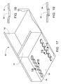
- Fig. 3 is a perspective schematic illustration of a redesigned, shop-fabricated wet scrubber tray with shop-installed intermediate stiffeners
- Fig. 4 is a perspective schematic illustration of a known, perforated wet scrubber tray with field-installed intermediate stiffeners
- Fig. 4A is a perspective schematic illustration of a field-installed intermediate stiffener of the type depicted in Fig. 4 ;
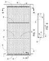
- Fig. 5 is a plan view of an embodiment of a shop-fabricated wet scrubber tray with shop-installed intermediate stiffeners
- Fig. 6 is a sectional view of Fig. 5 viewed in the direction of arrows 6-6 of Fig. 5 ;
- Fig. 7 is a sectional view of Fig. 5 viewed in the direction of arrows 7-7 of Fig. 5 ;
- Fig. 8 is a plan view of the hold-down plate and neoprene boots of Fig. 5 ;
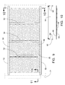
- Fig. 9 is a plan view of another example of a shop-fabricated wet scrubber tray with shop-installed intermediate stiffeners
- Fig. 10 is a sectional view of Fig. 9 viewed in the direction of arrows 10-10 of Fig. 9 ;
- Fig. 11 is a sectional view of Fig. 9 viewed in the direction of arrows 11-11 of Fig. 9 ;
- Fig. 12 is an illustration of a typical configuration of the bent plate angles of Fig. 11 used to secure the bottom tray plate of Fig. 11 ;
- Fig. 13 is a perspective schematic illustration view of another example of a stiffened wet scrubber tray
- Fig. 14 is a sectional view of Fig. 13 viewed in the direction of arrows 14-14 of Fig. 13 ;
- Fig. 15 is a perspective schematic illustration view of another example of a stiffened wet scrubber tray
- Fig. 16 is a sectional view of Fig. 15 viewed in the direction of arrows 16-16 of Fig. 15 ;
- Fig. 17 is a perspective schematic illustration view of another example of a stiffened wet scrubber tray
- Fig. 18 is a sectional view of Fig. 17 viewed in the direction of arrows 18-18 of Fig. 17 ;
- Fig. 19 is a sectional view of Fig. 17 viewed in the direction of arrows 19-19 of Fig. 17 ;
- Fig. 20 is a plan view of yet another example of a stiffened wet scrubber tray
- Fig. 21 is a sectional view of Fig. 20 viewed in the direction of arrows 21-21 of Fig. 20 ;
- Fig. 22 is a sectional view of Fig. 20 viewed in the direction of arrows 22-22 of Fig. 20 ;
- Fig. 23 is a sectional view of Fig. 20 viewed in the direction of arrows 23-23 of Fig. 20 ;
- Fig. 24 is a sectional view of Fig. 20 viewed in the direction of arrows 24-24 of Fig. 20 ;
- Fig. 25 is an end view of a portion of Fig. 20 viewed in the direction of arrows 25-25 of Fig. 20 ;
- Fig. 26 is a plan view of yet still another example of a stiffened wet scrubber tray
- Fig. 27 is a sectional view of Fig. 26 viewed in the direction of arrows 27-27 of Fig. 26 ;
- Fig. 28 is a sectional view of Fig. 26 viewed in the direction of arrows 28-28 of Fig. 26 ;
- Fig. 29 is a sectional view of Fig. 26 viewed in the direction of arrows 29-29 of Fig. 26 ;
- Fig. 30 is a close-up sectional view of the circled portion of Fig. 28 .
- the amplitude of the portions undergoing vibration is such that the stresses are exceeding the endurance limit, and the failures are due to fatigue.
- One way to reduce the amplitude of any component undergoing vibration at a given frequency is to increase the natural frequency of the component. Based upon the above relationship, increasing the stiffness-to-mass ratio of the component will increase the natural frequency. Thus, if the driving forces remain at the same frequency, stiffening the trays will reduce their likelihood to vibrate, thereby reducing the amplitude of vibration and the resulting flexural stresses experienced.
- the present invention thus provides several ways to increase the stiffness of the tray, increase natural frequency and reduce stress.
- FIG. 3 there is shown a perspective schematic illustration of a redesigned, shop-fabricated wet scrubber tray, generally designated 50, with shop-installed intermediate stiffeners.
- each of the new shop-fabricated trays 50 have equal height side stiffeners 52, rather than the unequal height side stiffeners of existing tray designs, plural intermediate stiffeners 54 (in this embodiment, two; three or more may be employed) and a perforated lower portion or bottom plate 56 (most of the perforations 36 have been omitted for clarity).
- the perforated plate 56 is provided with substantially symmetrically spaced relatively large openings or perforations 36 to form an open area therethrough; this open area can be provided by a plurality of holes or perforations 36 which may be 1-3/8 inch diameter.
- the perforations 36 may be provided on a staggered or straight-line pattern.
- the perforations 36 are also repositioned or "pulled away" from the edges of the perforated plate 56 so that they are moved away from the boundaries of the tray to reduce their influence on boundary conditions and thereby reduce the tendency for cracks to initiate.
- the intermediate stiffeners 54 can be L-shaped with a short leg S and a long leg L; this cross section provides stiffness both to the stiffeners 54 and the tray 50 to which they will be attached. The long leg of the stiffener 54 is placed against the tray bottom 56 upon installation. There are no welds of the intermediate stiffeners 54 to the tray bottom 56.
- the intermediate stiffeners 54 may be the same height as the side stiffeners 52, or they may have different height(s) if desired.
- the intermediate stiffeners 54 divide the tray 50 into compartments, and the two intermediate stiffeners 54 stabilize each of the side stiffeners 52 at two points.
- the trays 50 rest upon suitable structural support members 70 which establish and maintain the trays 50 in a substantially horizontal position.
- the support members 70 are attached to the walls of the spray tower absorber 14 and the trays 50 extend transversely across the spray tower absorber 14 as small or large elements forming a perforated barrier to gas flow upwardly and liquid flow downwardly through the spray tower absorber 14.
- a tie-down plate 58 and an elastomeric pad 60 made of a material such as rubber or, in the present examples, neoprene, are used to hold down adjacent ends of two adjoining trays 50 via fasteners 62.
- the fasteners 62 comprise a bolt welded to the support members and an associated washer and nut assembly.
- apertures can be provided in the tie-down plate 58 and notches can be provided in the elastomeric pad 60 to accept the fasteners.
- the elastomeric pad 60 may have different configurations; it may comprise a single pad which spans the adjacent ends of two adjoining trays 50, or it may comprise two U-shaped pads or boots which extend around the adjacent ends of two adjoining trays 50.
- Tray-to-tray groove welds 59 three in number in the present example, are provided between and at an upper edge of adjacent side stiffeners 52 of adjacent trays 50, and serve to strengthen both adjacent trays 50.
- the intermediate stiffeners 54 may be applied to the trays 50 in the shop, or they may be field installed.
- certain aspects of the shop-fabricated trays 50 described herein and their method of installation cannot be employed.
- the additional stiffening would be supplied primarily via the application of the intermediate stiffeners. Slight differences are thus required in the configuration of field-installed intermediate stiffeners 54 versus the configuration of shop-installed intermediate stiffeners 54 used in the construction of the shop-fabricated trays 50, as will be described in the following paragraphs.
- the intermediate stiffeners 54 span the distance between the side stiffeners 52 across the bottom plate 56 of the tray 50. Ends of the intermediate stiffeners 54 are shop welded at 68 to the side stiffeners 52.
- the bottom edge of each of the intermediate stiffeners 54 is provided with a plurality of straight fingers or tabs 64 which are spaced so as to correspond to slots 65 in the bottom 56 of the tray 50. The tabs 64 extend through the slots 65 and pass through corresponding slots in a strip 66 placed below the bottom 56 of the tray 50.
- the strip 66 is a 1 inch wide strip of metal also with slots 65 in it; the intermediate stiffeners' 54 tabs 64 protrude through the slots 65 in the bottom 56 of the tray 50 and into the corresponding slots 65 in the strip 66. The tabs 64 are then welded to the strip 66. There is no fusion of the strip 66 to the perforated bottom plate 56.
- the intermediate stiffeners 54 also span the distance between the side stiffeners 52 across the bottom plate 56 of the tray 50.
- the approach of welding straight fingers or tabs 64 to a strip 66 located beneath the tray 50 cannot be used because welding access to the underside of the tray 50 is unavailable.
- bent fingers 67 are provided along the bottom long leg edge of each of the field-installed intermediate stiffeners 54. The fingers 67 can be bent at an angle of greater than about 90 degrees with respect to the plane of the long side L of the intermediate stiffeners 54.
- the spacing of the bent fingers 67 along the bottom edge corresponds to the spacing of the perforations 36 in the bottom plate 56, and the size of each of the bent fingers 67 is such that they can be readily received by the perforations 36 during installation and contact adjacent ligaments to support the tray 50.
- Field installation of any of the intermediate stiffeners 54 is accomplished by locating an intermediate stiffener 54 above the bottom 56 of the tray 50 with the bent fingers 67 aligned with a corresponding perforation 36. The stiffener 54 is then tipped towards the bottom 56 of the tray 50 and the bent fingers 67 are engaged with their corresponding perforations 36.
- the stiffener 54 is then tipped back to vertical to engage the bent fingers 67 through the perforations 36, hooking them underneath the bottom 56 of the tray 50, thereby increasing the stiffness of the tray 50.
- the bent fingers 67 through the existing perforations 36 prevent downward deflection of the bottom 56 of the tray 50, while the flat bottom edge of the intermediate stiffener prevents upward deflection of the bottom 56 of the tray 50.
- the field-installed intermediate stiffeners 54 will help stabilize the side stiffeners 52 against warping due to turbulence and buffeting.
- the installation of these field-installed stiffeners 54 can be done in a relatively short amount of time such that an implementer does not have to endure an extended outage to fix the trays 50.
- trays 50 provided in wet scrubber absorber towers 14 are rectangular in shape with a center stiffener located between the long sides. It will thus be appreciated by those skilled in the art that while the term intermediate is often used in the present description to indicate that the added stiffeners of the present examples are typically placed in between an existing center stiffener and an end of the tray 50, it is possible to locate any of the additional stiffeners at any location along the tray 50, even at or near a central location. See Fig. 4 . In some installations, a stiffener is not provided at the center of a tray 50, and is located instead at some other location.
- non-symmetrical stiffener spacing along the tray which provides compartments of varying sizes may be employed to further reduce the possibility of the stiffeners being placed at vibrational node locations along the tray that might lead to undesirable vibrational behavior.
- Fig. 7 illustrates the use of the tie-down plate 58 and elastomeric pad or boot 60 and fasteners 62 to secure adjacent edges of trays 50 to a support beam or member 70.
- the elastomeric pad 60 is an extruded U-shape, and can be 3/16 inch thick, with a Shore Type A - 50 durometer hardness. The hardness may range between approximately 40 - 60 Shore Type A durometer hardness, depending upon the amount of dampening and preload desired, as well as economic concerns.
- Armaflex ® 520 adhesive available from Armaflex LLC of Mebane, NC) or equivalent is used to secure the elastomeric boot 60 to the tray 50 edges before tray shipment.
- FIG. 8 illustrates the assembled tie-down plate 58 and a neoprene boot 60; notches and/or apertures are provided in both parts to permit the fasteners 62 to extend therethrough for assembly and a notch is pre-cut into the boot 60 to permit drainage.
- Figs. 9, 10 , 11 and 12 illustrate another embodiment of how the ends of adjacent trays 50 may be held down at locations where the tray 50 supports have a different configuration.
- the support beam 72 is an inverted TEE shape comprised of a vertical plate 74 welded to a horizontal plate 76.
- the support beam 72 may itself be supported from a truss member extending across a diameter or chord of the wet scrubber 10.
- the ends of adjacent trays 50 rest upon the horizontal plate 76. Ends of the adjacent trays 50 are again provided with a neoprene boot 60, glued as before.
- Bent plate angles 78 of a desired length are then used to retain the ends of the trays 50 in place.
- Fig. 12 illustrates a typical configuration of the bent plate angles 78 and the placement of the field welds 82 used to secure the bent plate angles 78 to the support beam 72, including installations adjacent the outer curvature of the spray tower absorber 10 housing.
- Figs. 13 - 19 illustrate other ways to increase tray natural frequency by providing an increased stiffness to mass ratio. Some of these aspects may be used to influence scrubber performance.
- the increased tray 50 stiffness to mass ratio involves forming specific features in the trays 50. In some of these Figs., perforations 36 have been omitted for clarity; similarly, only one intermediate stiffener 54 is shown for clarity. These features include providing one or more reinforcing ribs 90 in the bottom 56 of the tray 50; these ribs can be stamped, bead rolled or bent into the surface of the bottom 56 of the tray 50.
- the ribs may run in any direction on the tray 50 in order to provide the desired stiffness, and may be a height of from 1 ⁇ 2 to twice the thickness of the bottom plate 56.
- various profiles of the ribs 90 such as triangular or semi-circular, may be used.
- a boss punched through or indented around the perforations 36 in the tray 50 may be provided.
- Figs. 20 - 30 illustrate still other ways to increase tray natural frequency by providing an increased stiffness to mass ratio. Some of these aspects may be used to influence scrubber performance.
- the increased tray 50 stiffness to mass ratio involves forming specific features in the trays 50. These features include providing one or more large domes or bulges 100 in the bottom 56 of the tray 50; these domes 100 can be stamped or bent into the surface of the bottom 56 of the tray 50. In one embodiment, each of the domes 100 may be on the order of about 15" diameter. In Figs. 20 - 25 , the domes 100 may be provided in each of the compartments created on the tray 50 by the intermediate stiffeners 54, approximately in the center portions thereof.
- domes 100 may be provided as features which extend above the surface of the bottom 56 of the tray 50, it is also possible to provide them as features which extend below the bottom surface 56 of the tray 50, in which case these features may also be referred to as large dimples 100.
- a plurality of smaller domes or bulges 110 may be provided in the bottom 56 of the tray 50.
- a plurality of these smaller domes or bulges 110 may be provided in each of the compartments created on the tray 50 by the intermediate stiffeners 54, spaced as desired in each compartment.
- each of the domes 110 may be on the order of about 3" diameter.
- these smaller domes or bulges are also possible to provide as features which extend below the bottom surface 56 of the tray 50, in which case these features may also be referred to as small dimples 110.
- the additional stiffness provided by these dome features can permit a reduction in thickness from 11 gauge to 14 gauge, resulting in a material savings of about 37%.
- a wet scrubber tray that can be provided with increased resistance to vibration-induced cracking.
- the tray is self supporting to eliminate wastage of raw material, and additional internal stiffeners added to the tray make multiple intermediate stiffeners.
- the connection of the intermediate stiffeners to the perforated bottom plate is changed to eliminate the shop weld in the bottom plate.
- the holes in the perforated bottom plate are repositioned so that they are moved away from the boundaries of the tray to reduce their influence on boundary conditions.
- the thickness of the tray material may be increased to lower the vibratory stresses.
- the mechanism for holding the trays themselves within the spray absorber tower is changed so that the trays are now held down by plate material that is attached to the support grid, but not to the trays.
- Elastomeric material such as neoprene is used at the tray-to-grid attachments to increase the damping of the system.
- Formed features in the trays such as single or multiple ribs, bosses, domes or dimples may also be provided to increase tray stiffness or influence wet scrubber performance.
Landscapes
- Chemical & Material Sciences (AREA)
- Chemical Kinetics & Catalysis (AREA)
- Engineering & Computer Science (AREA)
- Environmental & Geological Engineering (AREA)
- Health & Medical Sciences (AREA)
- Biomedical Technology (AREA)
- Analytical Chemistry (AREA)
- General Chemical & Material Sciences (AREA)
- Oil, Petroleum & Natural Gas (AREA)
- Treating Waste Gases (AREA)
- Gas Separation By Absorption (AREA)
- Physical Or Chemical Processes And Apparatus (AREA)
Abstract
Description
- The present invention relates to methods and apparatus for obtaining counter-current gas-liquid contact, such as wet scrubbers which involve gas-liquid contact between flue gas containing sulfur oxides and a slurry or solution containing reactive materials as a chemical reacting absorbing medium. More particularly, but not exclusively, the present invention is drawn to an improved wet scrubber tray construction and a gas-liquid contact apparatus employing same.
- Wet scrubber gas-liquid contact systems used for the removal of sulfur oxides (SOx) from flue gases produced from the combustion of fossil fuels are known. See for example
US Patent No. 4,263,021 to Downs et al ., the text of which is hereby incorporated by reference as though fully set forth herein. Additional details of wet scrubber systems for SOx removal are provided in Chapter 35 of Steam/its generation and use, 41st Edition, Kitto and Stultz, Eds., Copyright © 2005, The Babcock & Wilcox Company, the text of which is hereby incorporated by reference as though fully set forth herein. Such systems are also referred to as wet flue gas desulfurization (WFGD) systems. -
Figs. 1 and 2 illustrate components of one type of known wet scrubber system, generally designated 10, described in the aforementioned Steam 41st reference. SO2-laden flue gas 12 enters the side of the spray tower absorber 14 at approximately its midpoint and exits through atransition 16 at the top. The upper portion of the module (absorption zone 18) provides for the scrubbing of theflue gas 12 to remove the SO2 while the lower portion of the module serves as an integral slurry reaction tank (also frequently referred to as the recirculation tank and oxidation zone 20) to complete the chemical reactions to produce gypsum. Other key components shown include theslurry recirculation pumps 22, spray headers 24 (which may be conventional or interspatial design) and nozzles for slurry injection, moisture separators 26 (typically of a chevron design) to minimize moisture carryover, oxidizingair injection system 28, slurry reaction tank mixers oragitators 30 to prevent settling, and a perforatedtray 32 that reduces flue gas flow maldistribution to enhance SO2 removal performance. Flues leading from thetransition 16 convey the cleanedflue gas 34 from thewet scrubber 14. - The perforated
tray 32 is provided with a plurality of holes 36 (typically 1-3/8 inches diameter) and provides intimate gas/liquid contacting and increases the slurry residence time in the absorption zone. Thetray 32 creates more surface area between the slurry and theflue gas 12, and also provides significant holdup time for the slurry. This increases the limestone dissolution in theabsorption zone 18 and increases the absorption per unit volume. Some spray tower absorbers 14 have two levels of trays providing multiple contact zones for SO2 removal. Absorber modules that do not use a tray are referred to as open spray towers. - Recently, after a period of operation, some perforated trays have begun to exhibit cracking. This cracking has appeared in two areas.
- Crack
site 1. In the center stiffener, cracks were found at the end of the stiffener adjacent to a field weld joining the affected tray with its neighboring tray. These cracks were found to be initiating from the field welds, traveling horizontal into the center stiffener web. The orientation of the crack suggested that it was following a line of maximum bending stress caused by lateral movement of the top corner of the center stiffener. The forces causing this movement were thought to be random buffeting of the stiffener by flue gas and/or slurry spray. The initiation point at the field weld was caused by the Fatigue Strength Reduction Factor (FSRF) inherent to all welds. - Crack site 2. In the perforated bottom plate region adjacent to both the intermittent shop welds joining the center stiffener to the perforated bottom plate, and in the intermittent field welds connecting the trays to the steel support grid. The field welds are located at the end edges of the perforated bottom plate. The cracks were observed to initiate at the ends of the weld segments, traveling to the nearest hole in the perforated bottom plate. There were some instances where the cracks would initiate at both ends of a series of weld segments. This condition would effect the support boundary conditions of the perforated bottom plate in such a way that chaining of cracks would occur. This chaining effect had the potential of compromising the structural integrity of the perforated bottom plate, causing large sections of the perforated bottom plate to fall out, reducing the effectiveness of the function of the tray and creating a risk of pieces being sucked into the slurry recirculation pumps.
- Metallurgical examinations confirmed that the cracking was due to mechanical fatigue. This fatigue was thought to be induced by mechanical vibration from an unknown origin. No evidence of stress corrosion cracking or brittle fracture was found. The heat affected zone (HAZ) adjacent to the welds was also examined and found to be in satisfactory condition.
- The present invention has been conceived in the light of an identification by the inventors of the desirability of an improved wet scrubber perforated tray providing increased resistance to vibration-induced cracking whilst being simple in design, rugged in construction, and economical to manufacture. The various aspects of the present invention may exhibit one or more such features. Such features of the improved wet scrubber tray may be used singly or in any combination.
- Accordingly, one aspect of the present invention is drawn to a modification of the sides of the tray to make the tray self supporting and to eliminate wastage of raw material. The original tray design had a high side and a low side that required the field welding of the low tray side to the high side of its neighboring tray to complete its support requirements. This construction required an extra shearing operation by the tray fabricator and the subsequent wastage of material. By providing two, equal height, side stiffeners, the tray stiffness is markedly increased. This change also eliminated the difficult field weld of the low side to the neighboring high side. In addition, the elimination of this field weld helped solve the cracking problem at Crack Site 1.
- Another aspect of the present invention is drawn to the addition of an internal stiffener to the tray to make two intermediate stiffeners. The original design had one center stiffener that acted as a baffle for functional reasons, to stiffen the perforated bottom plate, and to provide a positive brace for the side stiffeners. The one problem with this design is that it still did not prevent the side stiffeners from warping. The addition of an internal stiffener eliminated the possibility of warping due to gas or spray buffeting. The previously mentioned aspect also worked to the benefit of this aspect by allowing for a shop weld to be applied at both ends of the intermediate stiffeners. The original tray design required field welding the center stiffener end to the neighboring tray high side. It is this field weld that provided the initiation point for the Crack
Site 1 cracking. With certain changes in the specific design of the intermediate stiffeners, the intermediate stiffeners may be shop-installed or field-installed. - Yet another aspect of the present invention is drawn to a change in the connection of the intermediate stiffeners to the perforated bottom plate to eliminate the shop weld in the bottom plate. This new arrangement, in one embodiment, uses a 1 inch strip of metal with slots in it to capture the bottom perforated plate. The same pattern of slots is in the perforated bottom plate. In this design the intermediate stiffeners have tabs on their bottom edges that will protrude through the slots. The tabs are then welded to the 1 inch strip. There is no fusion of the 1 inch strip to the perforated bottom plate. In addition, a welding sequence is specified to minimize residual weld stresses.
- Still another aspect of the present invention involves repositioning the holes in the perforated bottom plate so that they are moved away from the boundaries of the tray to reduce their influence on boundary conditions. This is especially true along the intermediate stiffeners where holes are arranged to provide a landing for the stiffener attachment slots.
- Yet still another aspect of the present invention involves increasing the thickness of the tray material to lower the vibratory stresses that are causing the cracking. This increase in thickness, along with the addition of the internal stiffener, will also increase the natural frequencies of the tray. It is well established that the displacements and stresses in a vibrating structure will decrease as the frequency increases. Lowering the vibratory stresses is probably the most effective way to reduce fatigue.
- Still another aspect of the present invention involves a change in the mechanism for holding the trays themselves within the spray absorber tower; according to the present invention, the trays are now held down by plate material that is attached to the support grid, but not to the trays. This feature was instituted primarily to get the remainder of the field welds out of the perforated bottom plate.
- Yet still another aspect of the present invention involves application of three field welds to the sides of each tray to hold the trays in place relative to each other. These field welds are much easier to make than the field welds on the original trays. In addition to holding the trays in place, these welds are strategically placed to allow adjacent side stiffeners to act together as a composite section, thus increasing their strength.
- Another aspect of the present invention involves the use of an elastomeric material such as neoprene material at the tray-to-grid attachments. This neoprene material was added in an effort to buffer the tray bottom plate from the sharp edge of the hold-down plate. Subsequent experimentation indicated that the neoprene material increases the damping of the system. It is scientific fact that introducing additional damping to a vibrating system decreases the responses of the system, thereby decreasing the stresses in the structure. The inclusion of this neoprene material also has the additional benefit of isolating the tray from any lateral motions or restraint imposed by the support grid. In one embodiment, an extruded neoprene "boot" that puts neoprene on both the top and bottom of the tray is used. Experimentation indicates that this supplies the greatest damping.
- Yet still another aspect of the present invention is drawn to a stiffened tray for a wet scrubber installation which employs one or more features such as reinforcing ribs in the bottom of the tray. The ribs may have various profiles and run in any direction on the tray in order to provide the desired stiffness. Alternatively, or in addition thereto, the perforations in the trays may be provided with a boss punched through or indented around the perforations. Still further, single or multiple domes or bulges, or dimples, may be provided in the trays to provide additional stiffness.
- If the desired stiffness is achieved via use of some or all of these features, instead of using thicker material for the trays, significant material cost savings can be realized. The reduced weight of trays made of more lightweight gauge materials also facilitates physical handling of the individual trays by shop manufacturing and field installation personnel.
- The various features of novelty which characterize the invention are pointed out with particularity in the claims annexed to and forming a part of this disclosure. For a better understanding of the invention, its operating advantages and the specific benefits attained by its uses, reference is made to the accompanying drawings and descriptive matter in which particular embodiments of the invention are illustrated.
- For a better understanding of the invention and to show how the same may be carried into effect reference is now made by way of example to the accompanying drawings in which:
-
Fig. 1 is a perspective elevation view, partly in section, of a known wet scrubber absorber tower; -
Fig. 2 is a perspective elevation view of the perforated tray used in the wet scrubber absorption tower ofFig. 1 ; -
Fig. 3 is a perspective schematic illustration of a redesigned, shop-fabricated wet scrubber tray with shop-installed intermediate stiffeners; -
Fig. 4 is a perspective schematic illustration of a known, perforated wet scrubber tray with field-installed intermediate stiffeners; -
Fig. 4A is a perspective schematic illustration of a field-installed intermediate stiffener of the type depicted inFig. 4 ; -
Fig. 5 is a plan view of an embodiment of a shop-fabricated wet scrubber tray with shop-installed intermediate stiffeners; -
Fig. 6 is a sectional view ofFig. 5 viewed in the direction of arrows 6-6 ofFig. 5 ; -
Fig. 7 is a sectional view ofFig. 5 viewed in the direction of arrows 7-7 ofFig. 5 ; -
Fig. 8 is a plan view of the hold-down plate and neoprene boots ofFig. 5 ; -
Fig. 9 is a plan view of another example of a shop-fabricated wet scrubber tray with shop-installed intermediate stiffeners; -
Fig. 10 is a sectional view ofFig. 9 viewed in the direction of arrows 10-10 ofFig. 9 ; -
Fig. 11 is a sectional view ofFig. 9 viewed in the direction of arrows 11-11 ofFig. 9 ; -
Fig. 12 is an illustration of a typical configuration of the bent plate angles ofFig. 11 used to secure the bottom tray plate ofFig. 11 ; -
Fig. 13 is a perspective schematic illustration view of another example of a stiffened wet scrubber tray; -
Fig. 14 is a sectional view ofFig. 13 viewed in the direction of arrows 14-14 ofFig. 13 ; -
Fig. 15 is a perspective schematic illustration view of another example of a stiffened wet scrubber tray; -
Fig. 16 is a sectional view ofFig. 15 viewed in the direction of arrows 16-16 ofFig. 15 ; -
Fig. 17 is a perspective schematic illustration view of another example of a stiffened wet scrubber tray; -
Fig. 18 is a sectional view ofFig. 17 viewed in the direction of arrows 18-18 ofFig. 17 ; -
Fig. 19 is a sectional view ofFig. 17 viewed in the direction of arrows 19-19 ofFig. 17 ; -
Fig. 20 is a plan view of yet another example of a stiffened wet scrubber tray; -
Fig. 21 is a sectional view ofFig. 20 viewed in the direction of arrows 21-21 ofFig. 20 ; -
Fig. 22 is a sectional view ofFig. 20 viewed in the direction of arrows 22-22 ofFig. 20 ; -
Fig. 23 is a sectional view ofFig. 20 viewed in the direction of arrows 23-23 ofFig. 20 ; -
Fig. 24 is a sectional view ofFig. 20 viewed in the direction of arrows 24-24 ofFig. 20 ; -
Fig. 25 is an end view of a portion ofFig. 20 viewed in the direction of arrows 25-25 ofFig. 20 ; -
Fig. 26 is a plan view of yet still another example of a stiffened wet scrubber tray; -
Fig. 27 is a sectional view ofFig. 26 viewed in the direction of arrows 27-27 ofFig. 26 ; -
Fig. 28 is a sectional view ofFig. 26 viewed in the direction of arrows 28-28 ofFig. 26 ; -
Fig. 29 is a sectional view ofFig. 26 viewed in the direction of arrows 29-29 ofFig. 26 ; and -
Fig. 30 is a close-up sectional view of the circled portion ofFig. 28 . - While the invention is susceptible to various modifications and alternative forms, specific embodiments are shown by way of example in the drawings and are herein described in detail. It should be understood, however, that drawings and detailed description thereto are not intended to limit the invention to the particular form disclosed, but on the contrary, the invention is to cover all modifications, equivalents and alternatives falling within the spirit and scope of the present invention as defined by the appended claims.
- The natural circular frequency of a single degree of freedom component can generally be represented by the relationship:

where: - ωn = circular frequency
- k = stiffness
- m = mass
- If the observed tray cracking is vibration-induced, the amplitude of the portions undergoing vibration is such that the stresses are exceeding the endurance limit, and the failures are due to fatigue. One way to reduce the amplitude of any component undergoing vibration at a given frequency is to increase the natural frequency of the component. Based upon the above relationship, increasing the stiffness-to-mass ratio of the component will increase the natural frequency. Thus, if the driving forces remain at the same frequency, stiffening the trays will reduce their likelihood to vibrate, thereby reducing the amplitude of vibration and the resulting flexural stresses experienced. The present invention thus provides several ways to increase the stiffness of the tray, increase natural frequency and reduce stress.
- Referring to the drawings generally, wherein like reference numerals designate the same or functionally similar elements throughout the several drawings, and to
Fig. 3 in particular, there is shown a perspective schematic illustration of a redesigned, shop-fabricated wet scrubber tray, generally designated 50, with shop-installed intermediate stiffeners. - As shown in
Fig. 3 , each of the new shop-fabricatedtrays 50 have equalheight side stiffeners 52, rather than the unequal height side stiffeners of existing tray designs, plural intermediate stiffeners 54 (in this embodiment, two; three or more may be employed) and a perforated lower portion or bottom plate 56 (most of theperforations 36 have been omitted for clarity). Theperforated plate 56 is provided with substantially symmetrically spaced relatively large openings orperforations 36 to form an open area therethrough; this open area can be provided by a plurality of holes orperforations 36 which may be 1-3/8 inch diameter. Theperforations 36 may be provided on a staggered or straight-line pattern. In accordance with one set of examples, theperforations 36 are also repositioned or "pulled away" from the edges of theperforated plate 56 so that they are moved away from the boundaries of the tray to reduce their influence on boundary conditions and thereby reduce the tendency for cracks to initiate. SeeFig. 5 . Theintermediate stiffeners 54 can be L-shaped with a short leg S and a long leg L; this cross section provides stiffness both to thestiffeners 54 and thetray 50 to which they will be attached. The long leg of thestiffener 54 is placed against the tray bottom 56 upon installation. There are no welds of theintermediate stiffeners 54 to thetray bottom 56. Theintermediate stiffeners 54 may be the same height as theside stiffeners 52, or they may have different height(s) if desired. Theintermediate stiffeners 54 divide thetray 50 into compartments, and the twointermediate stiffeners 54 stabilize each of theside stiffeners 52 at two points. - The
trays 50 rest upon suitablestructural support members 70 which establish and maintain thetrays 50 in a substantially horizontal position. Thesupport members 70 are attached to the walls of thespray tower absorber 14 and thetrays 50 extend transversely across thespray tower absorber 14 as small or large elements forming a perforated barrier to gas flow upwardly and liquid flow downwardly through thespray tower absorber 14. At each end of thetray 50, in contrast to prior practice of welding the tray to the supports in the field, a tie-down plate 58 and anelastomeric pad 60 made of a material such as rubber or, in the present examples, neoprene, are used to hold down adjacent ends of two adjoiningtrays 50 viafasteners 62. In some examples, thefasteners 62 comprise a bolt welded to the support members and an associated washer and nut assembly. As described later, apertures can be provided in the tie-down plate 58 and notches can be provided in theelastomeric pad 60 to accept the fasteners. Theelastomeric pad 60 may have different configurations; it may comprise a single pad which spans the adjacent ends of two adjoiningtrays 50, or it may comprise two U-shaped pads or boots which extend around the adjacent ends of two adjoiningtrays 50. Tray-to-tray groove welds 59, three in number in the present example, are provided between and at an upper edge of adjacent side stiffeners 52 ofadjacent trays 50, and serve to strengthen bothadjacent trays 50. - The
intermediate stiffeners 54 may be applied to thetrays 50 in the shop, or they may be field installed. In the case of field "fixes", certain aspects of the shop-fabricatedtrays 50 described herein and their method of installation cannot be employed. For example, since in an existing wet scrubber the trays may be welded to the supports, the use of the tie-down plate 58 and theelastomeric pad 60 to hold down adjacent ends of two adjoiningtrays 50 viafasteners 62 cannot be employed. In this case, the additional stiffening would be supplied primarily via the application of the intermediate stiffeners. Slight differences are thus required in the configuration of field-installedintermediate stiffeners 54 versus the configuration of shop-installedintermediate stiffeners 54 used in the construction of the shop-fabricatedtrays 50, as will be described in the following paragraphs. - As illustrated in
Figs. 5 - 7 , in the case of shop-installedintermediate stiffeners 54, theintermediate stiffeners 54 span the distance between theside stiffeners 52 across thebottom plate 56 of thetray 50. Ends of theintermediate stiffeners 54 are shop welded at 68 to theside stiffeners 52. The bottom edge of each of theintermediate stiffeners 54 is provided with a plurality of straight fingers ortabs 64 which are spaced so as to correspond toslots 65 in the bottom 56 of thetray 50. Thetabs 64 extend through theslots 65 and pass through corresponding slots in astrip 66 placed below the bottom 56 of thetray 50. In one embodiment, thestrip 66 is a 1 inch wide strip of metal also withslots 65 in it; the intermediate stiffeners' 54tabs 64 protrude through theslots 65 in the bottom 56 of thetray 50 and into the correspondingslots 65 in thestrip 66. Thetabs 64 are then welded to thestrip 66. There is no fusion of thestrip 66 to theperforated bottom plate 56. - As illustrated in
Figs. 4 and4A , in the case of field-installedintermediate stiffeners 54, theintermediate stiffeners 54 also span the distance between theside stiffeners 52 across thebottom plate 56 of thetray 50. However, the approach of welding straight fingers ortabs 64 to astrip 66 located beneath thetray 50 cannot be used because welding access to the underside of thetray 50 is unavailable. In this case longer,bent fingers 67 are provided along the bottom long leg edge of each of the field-installedintermediate stiffeners 54. Thefingers 67 can be bent at an angle of greater than about 90 degrees with respect to the plane of the long side L of theintermediate stiffeners 54. The spacing of thebent fingers 67 along the bottom edge corresponds to the spacing of theperforations 36 in thebottom plate 56, and the size of each of thebent fingers 67 is such that they can be readily received by theperforations 36 during installation and contact adjacent ligaments to support thetray 50. Field installation of any of theintermediate stiffeners 54 is accomplished by locating anintermediate stiffener 54 above the bottom 56 of thetray 50 with thebent fingers 67 aligned with a correspondingperforation 36. Thestiffener 54 is then tipped towards the bottom 56 of thetray 50 and thebent fingers 67 are engaged with their correspondingperforations 36. Thestiffener 54 is then tipped back to vertical to engage thebent fingers 67 through theperforations 36, hooking them underneath the bottom 56 of thetray 50, thereby increasing the stiffness of thetray 50. Thebent fingers 67 through the existingperforations 36 prevent downward deflection of the bottom 56 of thetray 50, while the flat bottom edge of the intermediate stiffener prevents upward deflection of the bottom 56 of thetray 50. - Field welds are then made between the ends of the
intermediate stiffeners 54 with the inside of theside stiffeners 52 and the existingside ledge 55; no other fusion welds are made between theintermediate stiffeners 54 and thetray 50. Alternatively, these field welds could be dispensed with if a stamped feature of theside stiffeners 52, such as a spring tang formed in theside stiffeners 52, is employed. During installation, as theintermediate stiffeners 54 are being tipped back to vertical to engage thebent fingers 67 through theperforations 36, the ends of theintermediate stiffeners 54 could then be drawn past the spring tang which would then snap back into place and hold theintermediate stiffeners 54 in place. The field-installedintermediate stiffeners 54 will help stabilize theside stiffeners 52 against warping due to turbulence and buffeting. In addition, the installation of these field-installedstiffeners 54 can be done in a relatively short amount of time such that an implementer does not have to endure an extended outage to fix thetrays 50. - Digressing for a moment,
most trays 50 provided in wet scrubber absorber towers 14 are rectangular in shape with a center stiffener located between the long sides. It will thus be appreciated by those skilled in the art that while the term intermediate is often used in the present description to indicate that the added stiffeners of the present examples are typically placed in between an existing center stiffener and an end of thetray 50, it is possible to locate any of the additional stiffeners at any location along thetray 50, even at or near a central location. SeeFig. 4 . In some installations, a stiffener is not provided at the center of atray 50, and is located instead at some other location. Further, while symmetrical locations of such stiffeners in thetray 50 might be preferred from a manufacturing standpoint, non-symmetrical stiffener spacing along the tray which provides compartments of varying sizes may be employed to further reduce the possibility of the stiffeners being placed at vibrational node locations along the tray that might lead to undesirable vibrational behavior. - Referring again to
Fig. 7, Fig. 7 illustrates the use of the tie-down plate 58 and elastomeric pad orboot 60 andfasteners 62 to secure adjacent edges oftrays 50 to a support beam ormember 70. Here, theelastomeric pad 60 is an extruded U-shape, and can be 3/16 inch thick, with a Shore Type A - 50 durometer hardness. The hardness may range between approximately 40 - 60 Shore Type A durometer hardness, depending upon the amount of dampening and preload desired, as well as economic concerns. Armaflex® 520 adhesive (available from Armaflex LLC of Mebane, NC) or equivalent is used to secure theelastomeric boot 60 to thetray 50 edges before tray shipment.Fig. 8 illustrates the assembled tie-down plate 58 and aneoprene boot 60; notches and/or apertures are provided in both parts to permit thefasteners 62 to extend therethrough for assembly and a notch is pre-cut into theboot 60 to permit drainage. -
Figs. 9, 10 ,11 and12 illustrate another embodiment of how the ends ofadjacent trays 50 may be held down at locations where thetray 50 supports have a different configuration. In this embodiment, thesupport beam 72 is an inverted TEE shape comprised of avertical plate 74 welded to ahorizontal plate 76. Thesupport beam 72 may itself be supported from a truss member extending across a diameter or chord of thewet scrubber 10. The ends ofadjacent trays 50 rest upon thehorizontal plate 76. Ends of theadjacent trays 50 are again provided with aneoprene boot 60, glued as before. Bent plate angles 78 of a desired length, and which may be straight or curved (if adjacent the curved outer shell of the wet scrubber 10), are then used to retain the ends of thetrays 50 in place.Fig. 12 illustrates a typical configuration of the bent plate angles 78 and the placement of the field welds 82 used to secure the bent plate angles 78 to thesupport beam 72, including installations adjacent the outer curvature of thespray tower absorber 10 housing. -
Figs. 13 - 19 illustrate other ways to increase tray natural frequency by providing an increased stiffness to mass ratio. Some of these aspects may be used to influence scrubber performance. The increasedtray 50 stiffness to mass ratio involves forming specific features in thetrays 50. In some of these Figs.,perforations 36 have been omitted for clarity; similarly, only oneintermediate stiffener 54 is shown for clarity. These features include providing one or more reinforcingribs 90 in the bottom 56 of thetray 50; these ribs can be stamped, bead rolled or bent into the surface of the bottom 56 of thetray 50. The ribs may run in any direction on thetray 50 in order to provide the desired stiffness, and may be a height of from ½ to twice the thickness of thebottom plate 56. In addition, various profiles of theribs 90, such as triangular or semi-circular, may be used. Alternatively, or in addition thereto, a boss punched through or indented around theperforations 36 in thetray 50 may be provided. -
Figs. 20 - 30 illustrate still other ways to increase tray natural frequency by providing an increased stiffness to mass ratio. Some of these aspects may be used to influence scrubber performance. The increasedtray 50 stiffness to mass ratio involves forming specific features in thetrays 50. These features include providing one or more large domes or bulges 100 in the bottom 56 of thetray 50; thesedomes 100 can be stamped or bent into the surface of the bottom 56 of thetray 50. In one embodiment, each of thedomes 100 may be on the order of about 15" diameter. InFigs. 20 - 25 , thedomes 100 may be provided in each of the compartments created on thetray 50 by theintermediate stiffeners 54, approximately in the center portions thereof. While thedomes 100 may be provided as features which extend above the surface of the bottom 56 of thetray 50, it is also possible to provide them as features which extend below thebottom surface 56 of thetray 50, in which case these features may also be referred to aslarge dimples 100. Alternatively, inFigs. 26 - 30 , a plurality of smaller domes or bulges 110 may be provided in the bottom 56 of thetray 50. A plurality of these smaller domes or bulges 110 may be provided in each of the compartments created on thetray 50 by theintermediate stiffeners 54, spaced as desired in each compartment. In one embodiment, each of thedomes 110 may be on the order of about 3" diameter. It is also possible to provide these smaller domes or bulges as features which extend below thebottom surface 56 of thetray 50, in which case these features may also be referred to assmall dimples 110. The additional stiffness provided by these dome features can permit a reduction in thickness from 11 gauge to 14 gauge, resulting in a material savings of about 37%. - Thus, viewed from one aspect, there has been described a wet scrubber tray that can be provided with increased resistance to vibration-induced cracking. The tray is self supporting to eliminate wastage of raw material, and additional internal stiffeners added to the tray make multiple intermediate stiffeners. The connection of the intermediate stiffeners to the perforated bottom plate is changed to eliminate the shop weld in the bottom plate. The holes in the perforated bottom plate are repositioned so that they are moved away from the boundaries of the tray to reduce their influence on boundary conditions. The thickness of the tray material may be increased to lower the vibratory stresses. The mechanism for holding the trays themselves within the spray absorber tower is changed so that the trays are now held down by plate material that is attached to the support grid, but not to the trays. Three field welds are applied to the sides of each tray to hold the trays in place relative to each other and are strategically placed to allow adjacent side stiffeners to act together as a composite section, thus increasing their strength. Elastomeric material such as neoprene is used at the tray-to-grid attachments to increase the damping of the system. Formed features in the trays such as single or multiple ribs, bosses, domes or dimples may also be provided to increase tray stiffness or influence wet scrubber performance.
- While the principles of the present invention may be particularly applicable to new wet scrubber installations, it will be appreciated that the present invention may be applied to construction involving the replacement, repair or modification of existing wet scrubbers. In some embodiments of the invention, certain features of the invention may sometimes be used to advantage without a corresponding use of the other features. Accordingly, while specific embodiments of the present invention have been shown and described in detail to illustrate the application and principles of the invention, it will be understood that it is not intended that the present invention be limited thereto and that the invention may be embodied otherwise without departing from such principles. All such changes and embodiments properly fall within the scope of the following claims.
Claims (20)
- A wet scrubber tray for a counter-current liquid gas contact device having walls defining an upright housing with a gas inlet and having means for passing gas upwardly therethrough, comprising: a perforated plate provided with substantially symmetrically spaced relatively large openings to form an open area therethrough; equal height side stiffeners extending from first opposing edges of the perforated plate and oriented substantially perpendicularly with respect thereto; one or more intermediate stiffeners in between the side stiffeners and connected thereto and to the plate; and features provided in the perforated plate, the stiffeners and the features serving to increase the stiffness to mass ratio of the tray which increases the tray's natural frequency in order to decrease the tray's susceptibility to vibration-induced cracking.
- The wet scrubber tray according to claim 1, wherein the features comprise at least one or more ribs in the perforated plate.
- The wet scrubber tray according to claim 1 or 2, wherein the features comprise bosses around the perforations in the perforated plate.
- The wet scrubber tray according to claim 1, 2 or 3, wherein the features comprise at least one or more domes or dimples in the perforated plate.
- The wet scrubber tray according to any preceding claim, wherein the tray comprises: a second set of opposed edges, each edge in the second set of opposed edges provided with interposed elastomeric material which contacts support members within the liquid gas contact device once the tray is installed therein, the elastomeric material providing additional damping to decrease the tray response to vibration and decrease the stresses in the tray, and isolating the tray from any lateral motions or restraint imposed by the support members.
- A stiffener for increasing the natural frequency of a perforated plate tray used in a wet scrubber, comprising: an L-shaped portion and a plurality of spaced tabs along an edge of a long leg of the L-shaped portion, the tabs adapted to be received through corresponding spaced slots of the perforated plate tray to permit the stiffener to be secured to the tray when a strip located beneath the tray is secured to the ends of the tabs.
- A stiffener for increasing the natural frequency of a perforated plate tray used in a wet scrubber, comprising: an L-shaped portion and a plurality of bent fingers along an edge of a long leg of the L-shaped portion, the bent fingers adapted to be received through corresponding spaced perforations of the perforated plate tray to permit the stiffener to be secured to the tray when the bent fingers are engaged to the tray through the perforations.
- A counter-current liquid gas contact device comprising walls defining an upright housing with a gas inlet and having means for passing gas upwardly therethrough one or more elevations of horizontally disposed trays comprised of perforated plates extending across the housing, each of the one or more perforated plates being perforated with substantially symmetrically spaced relatively large openings to form an open area through each of the one or more plates, adjacent ends of the perforated plates being secured to support members extending across the upright housing by a tie-down plate and interposed elastomeric material extending therebetween.
- The device according to claim 8, wherein each of the trays are provided with side stiffeners and plural intermediate stiffeners connected in between the side stiffeners, and wherein the side stiffeners of one tray are welded at an upper edge to side stiffeners of adjacent trays.
- The device according to claim 9, wherein the intermediate stiffeners are provided with tabs on a lower edge thereof, the tabs extending through corresponding slots in the perforated plates and slots in a strip placed below the bottom of the tray, the tabs of the intermediate stiffeners being welded to the strip and the ends of the intermediate stiffeners being welded to the side stiffeners to secure the intermediate stiffeners to the tray.
- The device according to claim 9 or 10, wherein the intermediate stiffeners are provided with bent fingers on a lower edge thereof, the bent fingers extending through corresponding openings in the perforated plates and engaging the bottom of the tray, the ends of the intermediate stiffeners being engaged to the side stiffeners to secure the intermediate stiffeners to the tray.
- The device according to claim 11, wherein the ends of the intermediate stiffeners are welded only to the side stiffeners.
- The device according to claim 11 or 12, wherein the ends of the intermediate stiffeners are engaged with a spring tang formed in the side stiffeners.
- The device according to claim 8, comprising fasteners for securing the tie-down plate and interposed elastomeric material to the support members.
- The device according to any of claims 8 to 14, comprising bent plate angles for securing the tie-down plate and interposed elastomeric material to the support members.
- The device according to any of claims 8 to 15, wherein the interposed elastomeric material comprises neoprene.
- The device according to any of claims 8 to 16, comprising features in the perforated plates which provide the trays with an increased stiffness to mass ratio which increases the trays natural frequency in order to decrease the trays' susceptibility to vibration-induced cracking.
- The device according to claim 17, wherein the features comprise at least one or more ribs in the perforated plates.
- The device according to claim 17 or 18, wherein the features comprise bosses around the perforations in the perforated plates.
- The device according to claim 17, 18 or 19, wherein the features comprise at least one or more domes or dimples in the perforated plates.
Priority Applications (1)
| Application Number | Priority Date | Filing Date | Title |
|---|---|---|---|
| PL09162862T PL2135663T3 (en) | 2008-06-16 | 2009-06-16 | Wet scrubber tray |
Applications Claiming Priority (2)
| Application Number | Priority Date | Filing Date | Title |
|---|---|---|---|
| US6190008P | 2008-06-16 | 2008-06-16 | |
| US12/484,187 US8413967B2 (en) | 2008-06-16 | 2009-06-13 | Wet scrubber tray |
Publications (3)
| Publication Number | Publication Date |
|---|---|
| EP2135663A2 true EP2135663A2 (en) | 2009-12-23 |
| EP2135663A3 EP2135663A3 (en) | 2010-04-07 |
| EP2135663B1 EP2135663B1 (en) | 2014-03-26 |
Family
ID=41130575
Family Applications (1)
| Application Number | Title | Priority Date | Filing Date |
|---|---|---|---|
| EP09162862.8A Not-in-force EP2135663B1 (en) | 2008-06-16 | 2009-06-16 | Wet scrubber tray |
Country Status (9)
| Country | Link |
|---|---|
| US (2) | US8413967B2 (en) |
| EP (1) | EP2135663B1 (en) |
| CA (2) | CA2672455C (en) |
| DK (1) | DK2135663T3 (en) |
| ES (1) | ES2456336T3 (en) |
| IL (1) | IL199363A (en) |
| PL (1) | PL2135663T3 (en) |
| PT (1) | PT2135663E (en) |
| TW (1) | TWI501803B (en) |
Cited By (3)
| Publication number | Priority date | Publication date | Assignee | Title |
|---|---|---|---|---|
| CN106362568A (en) * | 2016-08-26 | 2017-02-01 | 江苏中圣高科技产业有限公司 | Overturn-type ammonia-process desulfurization device |
| CN107088314A (en) * | 2017-06-27 | 2017-08-25 | 山东鼎裕生物能源有限公司 | A kind of rectifying column |
| CN111928085A (en) * | 2020-08-24 | 2020-11-13 | 中国十七冶集团有限公司 | Height-adjustable supporting device for construction machinery and using method thereof |
Families Citing this family (11)
| Publication number | Priority date | Publication date | Assignee | Title |
|---|---|---|---|---|
| US8413967B2 (en) * | 2008-06-16 | 2013-04-09 | Babcock & Wilcox Power Generation Group, Inc. | Wet scrubber tray |
| US8833742B2 (en) * | 2011-09-09 | 2014-09-16 | Uop Llc | Co-current vapor-liquid contacting apparatuses for offshore processes |
| US9669327B2 (en) * | 2015-04-10 | 2017-06-06 | Gti Solutions International, Llc | Vapor-liquid contact tray including interlocking joint |
| US10046274B2 (en) | 2015-08-28 | 2018-08-14 | Big Monkey Services, LLC. | Methods and systems for inhibiting crystalline buildup in a flue gas desulfurization unit |
| US10227247B2 (en) | 2016-05-26 | 2019-03-12 | Big Monkey Services, Llc | Methods and systems for remediation of heavy metals in combustion waste |
| US10421981B2 (en) | 2017-02-21 | 2019-09-24 | Big Monkey Services, Llc | Methods and systems for producing short chain weak organic acids from carbon dioxide |
| RU2662496C1 (en) * | 2017-08-15 | 2018-07-26 | Александр Дмитриевич Рязановский | Device for fixing the modules of a composite gas-liquid exchange grate |
| PT3468694T (en) | 2017-08-16 | 2024-04-03 | Doosan Lentjes Gmbh | A scrubber tray and a wet scrubber tower comprising such scrubber tray |
| US10953342B2 (en) | 2018-02-28 | 2021-03-23 | Uop Llc | Clip for supporting vessel internals, assembly and method of assembly |
| KR102620035B1 (en) | 2019-03-29 | 2023-12-29 | 미츠비시 파워 가부시키가이샤 | flue gas desulfurization device |
| CN111729500A (en) * | 2020-07-28 | 2020-10-02 | 中国华电科工集团有限公司 | Novel tray of assembled anticreep high strength |
Citations (1)
| Publication number | Priority date | Publication date | Assignee | Title |
|---|---|---|---|---|
| US4263021A (en) | 1972-12-05 | 1981-04-21 | The Babcock & Wilcox Company | Gas-liquid contact system |
Family Cites Families (32)
| Publication number | Priority date | Publication date | Assignee | Title |
|---|---|---|---|---|
| US267359A (en) * | 1882-11-14 | messer | ||
| US1749266A (en) * | 1928-01-09 | 1930-03-04 | Sontag Walter | Baffling device |
| US2375409A (en) * | 1942-07-27 | 1945-05-08 | Glitsch & Sons Fritz W | Fastening device |
| US2611596A (en) * | 1948-07-23 | 1952-09-23 | Glitsch Engineering Company | Tray for use in refining towers |
| US2611457A (en) * | 1948-10-08 | 1952-09-23 | Glitsch Engineering Company | Refining vessel |
| US2681820A (en) * | 1952-02-16 | 1954-06-22 | Gilbert & Barker Mfg Co | Manway cover clamp |
| US2652239A (en) * | 1952-03-29 | 1953-09-15 | Standard Oil Dev Co | Fractionation and distillation tray structure |
| NL85118C (en) | 1952-10-25 | |||
| BE521234A (en) * | 1953-06-10 | |||
| US2767967A (en) * | 1953-09-04 | 1956-10-23 | Stone & Webster Eng Corp | Fractionating tray |
| US2926754A (en) * | 1956-02-29 | 1960-03-01 | Edw G Ragatz Co | Method for improved mechanical effectiveness and efficiency of component interchangeon a vapor liquid contacting tray |
| US2931469A (en) | 1956-04-16 | 1960-04-05 | Shell Oil Co | Contacting tray assembly |
| US2916272A (en) | 1957-08-16 | 1959-12-08 | Edw G Ragatz Co | Column tray-structure |
| NL142078B (en) * | 1964-08-18 | 1974-05-15 | Shell Int Research | DISH FOR CONTACTING LIQUIDS AND GASES. |
| GB1350909A (en) | 1970-06-15 | 1974-04-24 | Swemco Ltd | Impingement baffle plate assembly |
| US4171333A (en) * | 1977-05-16 | 1979-10-16 | Norton Company | Tower packing support |
| DE3346740A1 (en) | 1983-12-23 | 1985-06-27 | Krupp Industrietechnik GmbH Werk Buckau Wolf, 4048 Grevenbroich | VIBRATION-FREE REPLACEMENT FLOORS |
| JPS63503522A (en) * | 1986-05-29 | 1988-12-22 | ウクラインスキ ナウチノ イスレドヴァテルスキ インスチテュート プリロドニク ガゾフ “ウクルニイガズ” | mass transfer equipment |
| US5246471A (en) * | 1992-02-07 | 1993-09-21 | The Babcock & Wilcox Company | Method and apparatus for gas liquid contact |
| US6267359B1 (en) * | 1995-04-26 | 2001-07-31 | Stone & Webster Engineering Corp. | Advanced tray support system using orthogonal grillage |
| US5573714A (en) * | 1995-06-15 | 1996-11-12 | Uop | Splice support construction of multiple downcomer fractionation tray |
| US6113079A (en) * | 1999-03-24 | 2000-09-05 | Uop Llc | Adjustable circumference fractionation tray and method of installation |
| JP2003033601A (en) * | 2001-07-23 | 2003-02-04 | Nippon Shokubai Co Ltd | Perforated plate tower with no weir |
| US6565071B2 (en) * | 2001-10-11 | 2003-05-20 | Amt International, Inc. | Liquid/gas contacting apparatus |
| US6592106B1 (en) | 2002-01-08 | 2003-07-15 | Koch-Glitsch, Lp | Locking hinged joint for vapor-liquid contact trays |
| US7028995B2 (en) * | 2002-07-29 | 2006-04-18 | Koch-Glitsch, Lp | Vapor-liquid contact trays and method employing same |
| US6923852B2 (en) * | 2002-10-24 | 2005-08-02 | The Babcock & Wilcox Company | Flue gas desulfurization system with a stepped tray |
| US7270315B2 (en) * | 2004-09-28 | 2007-09-18 | Amt International, Inc. | Exchange column, perforated tray assembly |
| FR2878766B1 (en) * | 2004-12-08 | 2007-06-22 | Total France Sa | INTERNAL PLATEAU FOR ENCLOSURE |
| US7707782B2 (en) | 2005-02-10 | 2010-05-04 | The Babcock & Wilcox Power Generation Group, Inc. | Absorber tower metal hood to concrete shell attachment |
| US7810796B2 (en) * | 2006-12-14 | 2010-10-12 | Uop Llc | Dead zone activation in vapor-liquid contacting apparatus |
| US8413967B2 (en) * | 2008-06-16 | 2013-04-09 | Babcock & Wilcox Power Generation Group, Inc. | Wet scrubber tray |
-
2009
- 2009-06-13 US US12/484,187 patent/US8413967B2/en active Active
- 2009-06-15 IL IL199363A patent/IL199363A/en active IP Right Grant
- 2009-06-15 TW TW098119941A patent/TWI501803B/en active
- 2009-06-16 DK DK09162862.8T patent/DK2135663T3/en active
- 2009-06-16 CA CA2672455A patent/CA2672455C/en not_active Expired - Fee Related
- 2009-06-16 CA CA2850735A patent/CA2850735C/en not_active Expired - Fee Related
- 2009-06-16 ES ES09162862.8T patent/ES2456336T3/en active Active
- 2009-06-16 EP EP09162862.8A patent/EP2135663B1/en not_active Not-in-force
- 2009-06-16 PT PT91628628T patent/PT2135663E/en unknown
- 2009-06-16 PL PL09162862T patent/PL2135663T3/en unknown
-
2013
- 2013-03-12 US US13/797,003 patent/US8777190B2/en active Active
Patent Citations (1)
| Publication number | Priority date | Publication date | Assignee | Title |
|---|---|---|---|---|
| US4263021A (en) | 1972-12-05 | 1981-04-21 | The Babcock & Wilcox Company | Gas-liquid contact system |
Cited By (4)
| Publication number | Priority date | Publication date | Assignee | Title |
|---|---|---|---|---|
| CN106362568A (en) * | 2016-08-26 | 2017-02-01 | 江苏中圣高科技产业有限公司 | Overturn-type ammonia-process desulfurization device |
| CN107088314A (en) * | 2017-06-27 | 2017-08-25 | 山东鼎裕生物能源有限公司 | A kind of rectifying column |
| CN107088314B (en) * | 2017-06-27 | 2022-08-09 | 山东鼎裕生物能源有限公司 | Rectifying tower |
| CN111928085A (en) * | 2020-08-24 | 2020-11-13 | 中国十七冶集团有限公司 | Height-adjustable supporting device for construction machinery and using method thereof |
Also Published As
| Publication number | Publication date |
|---|---|
| CA2850735C (en) | 2015-10-20 |
| CA2850735A1 (en) | 2009-12-16 |
| CA2672455A1 (en) | 2009-12-16 |
| PL2135663T3 (en) | 2014-11-28 |
| TWI501803B (en) | 2015-10-01 |
| CA2672455C (en) | 2014-09-09 |
| US8413967B2 (en) | 2013-04-09 |
| EP2135663B1 (en) | 2014-03-26 |
| PT2135663E (en) | 2014-05-07 |
| DK2135663T3 (en) | 2014-05-19 |
| US8777190B2 (en) | 2014-07-15 |
| US20090309245A1 (en) | 2009-12-17 |
| US20130264725A1 (en) | 2013-10-10 |
| EP2135663A3 (en) | 2010-04-07 |
| IL199363A0 (en) | 2011-08-01 |
| ES2456336T3 (en) | 2014-04-22 |
| IL199363A (en) | 2014-01-30 |
| TW201008631A (en) | 2010-03-01 |
Similar Documents
| Publication | Publication Date | Title |
|---|---|---|
| CA2672455C (en) | Wet scrubber tray | |
| US9295926B2 (en) | Cross flow tray and support system for use in a mass transfer column | |
| US7125005B2 (en) | Contact tray having tray supported downcomers | |
| JP5844393B2 (en) | Apparatus for supporting internal structure of mass transfer column and process using the same | |
| WO2012158683A2 (en) | Use of downcomer beam to support adjacent cross flow trays within a mass transfer column and process involving same | |
| US7445200B2 (en) | Gas-liquid contactor baffle | |
| US11833457B2 (en) | Support beam for supporting internals within a mass transfer column | |
| ZA200904174B (en) | Wet scrubber tray | |
| KR20200128831A (en) | Ceiling connecting hardware and ceiling system | |
| US5045247A (en) | Bubble cap assembly | |
| JPWO2014017111A1 (en) | Gas separator and filler | |
| JP5732341B2 (en) | Sound absorption panel | |
| TWI738266B (en) | Flue gas desulfurization device | |
| JP4411444B2 (en) | Shear panel type damper mounting structure to structure | |
| JP4354390B2 (en) | Vibration control device for wooden houses | |
| JPH027633Y2 (en) | ||
| JPH0128810Y2 (en) | ||
| JPH0128812Y2 (en) | ||
| JPH0128811Y2 (en) | ||
| RU2662496C1 (en) | Device for fixing the modules of a composite gas-liquid exchange grate | |
| JPH027632Y2 (en) | ||
| US20080264262A1 (en) | Supporting structure for the nozzle-spraying plant of a drop separator system | |
| JPH0620655U (en) | Ceiling structure |
Legal Events
| Date | Code | Title | Description |
|---|---|---|---|
| PUAI | Public reference made under article 153(3) epc to a published international application that has entered the european phase |
Free format text: ORIGINAL CODE: 0009012 |
|
| AK | Designated contracting states |
Kind code of ref document: A2 Designated state(s): AT BE BG CH CY CZ DE DK EE ES FI FR GB GR HR HU IE IS IT LI LT LU LV MC MK MT NL NO PL PT RO SE SI SK TR |
|
| PUAL | Search report despatched |
Free format text: ORIGINAL CODE: 0009013 |
|
| AK | Designated contracting states |
Kind code of ref document: A3 Designated state(s): AT BE BG CH CY CZ DE DK EE ES FI FR GB GR HR HU IE IS IT LI LT LU LV MC MK MT NL NO PL PT RO SE SI SK TR |
|
| AX | Request for extension of the european patent |
Extension state: AL BA RS |
|
| RIC1 | Information provided on ipc code assigned before grant |
Ipc: B01D 3/32 20060101AFI20100303BHEP |
|
| 17P | Request for examination filed |
Effective date: 20100526 |
|
| 17Q | First examination report despatched |
Effective date: 20100625 |
|
| GRAP | Despatch of communication of intention to grant a patent |
Free format text: ORIGINAL CODE: EPIDOSNIGR1 |
|
| INTG | Intention to grant announced |
Effective date: 20131025 |
|
| GRAS | Grant fee paid |
Free format text: ORIGINAL CODE: EPIDOSNIGR3 |
|
| GRAA | (expected) grant |
Free format text: ORIGINAL CODE: 0009210 |
|
| AK | Designated contracting states |
Kind code of ref document: B1 Designated state(s): AT BE BG CH CY CZ DE DK EE ES FI FR GB GR HR HU IE IS IT LI LT LU LV MC MK MT NL NO PL PT RO SE SI SK TR |
|
| REG | Reference to a national code |
Ref country code: GB Ref legal event code: FG4D |
|
| REG | Reference to a national code |
Ref country code: CH Ref legal event code: EP |
|
| REG | Reference to a national code |
Ref country code: AT Ref legal event code: REF Ref document number: 658644 Country of ref document: AT Kind code of ref document: T Effective date: 20140415 |
|
| REG | Reference to a national code |
Ref country code: ES Ref legal event code: FG2A Ref document number: 2456336 Country of ref document: ES Kind code of ref document: T3 Effective date: 20140422 |
|
| REG | Reference to a national code |
Ref country code: PT Ref legal event code: SC4A Free format text: AVAILABILITY OF NATIONAL TRANSLATION Effective date: 20140429 Ref country code: IE Ref legal event code: FG4D |
|
| REG | Reference to a national code |
Ref country code: DE Ref legal event code: R096 Ref document number: 602009022714 Country of ref document: DE Effective date: 20140508 |
|
| REG | Reference to a national code |
Ref country code: DK Ref legal event code: T3 Effective date: 20140515 |
|
| REG | Reference to a national code |
Ref country code: RO Ref legal event code: EPE |
|
| PG25 | Lapsed in a contracting state [announced via postgrant information from national office to epo] |
Ref country code: LT Free format text: LAPSE BECAUSE OF FAILURE TO SUBMIT A TRANSLATION OF THE DESCRIPTION OR TO PAY THE FEE WITHIN THE PRESCRIBED TIME-LIMIT Effective date: 20140326 Ref country code: NO Free format text: LAPSE BECAUSE OF FAILURE TO SUBMIT A TRANSLATION OF THE DESCRIPTION OR TO PAY THE FEE WITHIN THE PRESCRIBED TIME-LIMIT Effective date: 20140626 |
|
| REG | Reference to a national code |
Ref country code: NL Ref legal event code: VDEP Effective date: 20140326 |
|
| REG | Reference to a national code |
Ref country code: LT Ref legal event code: MG4D |
|
| PG25 | Lapsed in a contracting state [announced via postgrant information from national office to epo] |
Ref country code: SE Free format text: LAPSE BECAUSE OF FAILURE TO SUBMIT A TRANSLATION OF THE DESCRIPTION OR TO PAY THE FEE WITHIN THE PRESCRIBED TIME-LIMIT Effective date: 20140326 Ref country code: FI Free format text: LAPSE BECAUSE OF FAILURE TO SUBMIT A TRANSLATION OF THE DESCRIPTION OR TO PAY THE FEE WITHIN THE PRESCRIBED TIME-LIMIT Effective date: 20140326 |
|
| REG | Reference to a national code |
Ref country code: SK Ref legal event code: T3 Ref document number: E 16516 Country of ref document: SK |
|
| PG25 | Lapsed in a contracting state [announced via postgrant information from national office to epo] |
Ref country code: HR Free format text: LAPSE BECAUSE OF FAILURE TO SUBMIT A TRANSLATION OF THE DESCRIPTION OR TO PAY THE FEE WITHIN THE PRESCRIBED TIME-LIMIT Effective date: 20140326 Ref country code: LV Free format text: LAPSE BECAUSE OF FAILURE TO SUBMIT A TRANSLATION OF THE DESCRIPTION OR TO PAY THE FEE WITHIN THE PRESCRIBED TIME-LIMIT Effective date: 20140326 |
|
| PG25 | Lapsed in a contracting state [announced via postgrant information from national office to epo] |
Ref country code: BG Free format text: LAPSE BECAUSE OF FAILURE TO SUBMIT A TRANSLATION OF THE DESCRIPTION OR TO PAY THE FEE WITHIN THE PRESCRIBED TIME-LIMIT Effective date: 20140626 Ref country code: EE Free format text: LAPSE BECAUSE OF FAILURE TO SUBMIT A TRANSLATION OF THE DESCRIPTION OR TO PAY THE FEE WITHIN THE PRESCRIBED TIME-LIMIT Effective date: 20140326 Ref country code: BE Free format text: LAPSE BECAUSE OF FAILURE TO SUBMIT A TRANSLATION OF THE DESCRIPTION OR TO PAY THE FEE WITHIN THE PRESCRIBED TIME-LIMIT Effective date: 20140326 Ref country code: NL Free format text: LAPSE BECAUSE OF FAILURE TO SUBMIT A TRANSLATION OF THE DESCRIPTION OR TO PAY THE FEE WITHIN THE PRESCRIBED TIME-LIMIT Effective date: 20140326 Ref country code: CY Free format text: LAPSE BECAUSE OF FAILURE TO SUBMIT A TRANSLATION OF THE DESCRIPTION OR TO PAY THE FEE WITHIN THE PRESCRIBED TIME-LIMIT Effective date: 20140326 Ref country code: IS Free format text: LAPSE BECAUSE OF FAILURE TO SUBMIT A TRANSLATION OF THE DESCRIPTION OR TO PAY THE FEE WITHIN THE PRESCRIBED TIME-LIMIT Effective date: 20140726 |
|
| REG | Reference to a national code |
Ref country code: PL Ref legal event code: T3 |
|
| REG | Reference to a national code |
Ref country code: DE Ref legal event code: R097 Ref document number: 602009022714 Country of ref document: DE |
|
| PG25 | Lapsed in a contracting state [announced via postgrant information from national office to epo] |
Ref country code: LU Free format text: LAPSE BECAUSE OF FAILURE TO SUBMIT A TRANSLATION OF THE DESCRIPTION OR TO PAY THE FEE WITHIN THE PRESCRIBED TIME-LIMIT Effective date: 20140616 Ref country code: MC Free format text: LAPSE BECAUSE OF FAILURE TO SUBMIT A TRANSLATION OF THE DESCRIPTION OR TO PAY THE FEE WITHIN THE PRESCRIBED TIME-LIMIT Effective date: 20140326 |
|
| PLBE | No opposition filed within time limit |
Free format text: ORIGINAL CODE: 0009261 |
|
| REG | Reference to a national code |
Ref country code: CH Ref legal event code: PL |
|
| STAA | Information on the status of an ep patent application or granted ep patent |
Free format text: STATUS: NO OPPOSITION FILED WITHIN TIME LIMIT |
|
| 26N | No opposition filed |
Effective date: 20150106 |
|
| REG | Reference to a national code |
Ref country code: IE Ref legal event code: MM4A |
|
| REG | Reference to a national code |
Ref country code: FR Ref legal event code: ST Effective date: 20150227 |
|
| REG | Reference to a national code |
Ref country code: DE Ref legal event code: R097 Ref document number: 602009022714 Country of ref document: DE Effective date: 20150106 |
|
| PG25 | Lapsed in a contracting state [announced via postgrant information from national office to epo] |
Ref country code: IE Free format text: LAPSE BECAUSE OF NON-PAYMENT OF DUE FEES Effective date: 20140616 Ref country code: CH Free format text: LAPSE BECAUSE OF NON-PAYMENT OF DUE FEES Effective date: 20140630 Ref country code: LI Free format text: LAPSE BECAUSE OF NON-PAYMENT OF DUE FEES Effective date: 20140630 |
|
| PG25 | Lapsed in a contracting state [announced via postgrant information from national office to epo] |
Ref country code: FR Free format text: LAPSE BECAUSE OF NON-PAYMENT OF DUE FEES Effective date: 20140630 |
|
| REG | Reference to a national code |
Ref country code: HU Ref legal event code: AG4A Ref document number: E022791 Country of ref document: HU |
|
| PG25 | Lapsed in a contracting state [announced via postgrant information from national office to epo] |
Ref country code: SI Free format text: LAPSE BECAUSE OF FAILURE TO SUBMIT A TRANSLATION OF THE DESCRIPTION OR TO PAY THE FEE WITHIN THE PRESCRIBED TIME-LIMIT Effective date: 20140326 |
|
| REG | Reference to a national code |
Ref country code: DE Ref legal event code: R082 Ref document number: 602009022714 Country of ref document: DE Representative=s name: D YOUNG & CO LLP, GB Ref country code: DE Ref legal event code: R081 Ref document number: 602009022714 Country of ref document: DE Owner name: THE BABCOCK & WILCOX CO., BARBERTON, US Free format text: FORMER OWNER: BABCOCK & WILCOX POWER GENERATION GROUP, INC., BARBERTON, OHIO, US |
|
| PG25 | Lapsed in a contracting state [announced via postgrant information from national office to epo] |
Ref country code: MT Free format text: LAPSE BECAUSE OF FAILURE TO SUBMIT A TRANSLATION OF THE DESCRIPTION OR TO PAY THE FEE WITHIN THE PRESCRIBED TIME-LIMIT Effective date: 20140326 |
|
| REG | Reference to a national code |
Ref country code: AT Ref legal event code: HC Ref document number: 658644 Country of ref document: AT Kind code of ref document: T Owner name: THE BABCOCK & WILCOX COMPANY, US Effective date: 20160411 |
|
| REG | Reference to a national code |
Ref country code: HU Ref legal event code: HC9C Owner name: THE BABCOCK & WILCOX COMPANY, US Free format text: FORMER OWNER(S): BABCOCK & WILCOX POWER GENERATION GROUP, INC., US |
|
| REG | Reference to a national code |
Ref country code: ES Ref legal event code: PC2A Owner name: THE BABCOCK & WILCOX COMPANY Effective date: 20160603 |
|
| PG25 | Lapsed in a contracting state [announced via postgrant information from national office to epo] |
Ref country code: GR Free format text: LAPSE BECAUSE OF FAILURE TO SUBMIT A TRANSLATION OF THE DESCRIPTION OR TO PAY THE FEE WITHIN THE PRESCRIBED TIME-LIMIT Effective date: 20140627 |
|
| PG25 | Lapsed in a contracting state [announced via postgrant information from national office to epo] |
Ref country code: TR Free format text: LAPSE BECAUSE OF FAILURE TO SUBMIT A TRANSLATION OF THE DESCRIPTION OR TO PAY THE FEE WITHIN THE PRESCRIBED TIME-LIMIT Effective date: 20140326 |
|
| REG | Reference to a national code |
Ref country code: SK Ref legal event code: TC4A Ref document number: E 16516 Country of ref document: SK Owner name: THE BABCOCK & WILCOX COMPANY, BARBERTON, OHIO, US Effective date: 20160721 |
|
| PG25 | Lapsed in a contracting state [announced via postgrant information from national office to epo] |
Ref country code: MK Free format text: LAPSE BECAUSE OF FAILURE TO SUBMIT A TRANSLATION OF THE DESCRIPTION OR TO PAY THE FEE WITHIN THE PRESCRIBED TIME-LIMIT Effective date: 20140326 |
|
| PGFP | Annual fee paid to national office [announced via postgrant information from national office to epo] |
Ref country code: CZ Payment date: 20200604 Year of fee payment: 12 Ref country code: DE Payment date: 20200629 Year of fee payment: 12 Ref country code: PT Payment date: 20200605 Year of fee payment: 12 Ref country code: DK Payment date: 20200629 Year of fee payment: 12 Ref country code: RO Payment date: 20200604 Year of fee payment: 12 |
|
| PGFP | Annual fee paid to national office [announced via postgrant information from national office to epo] |
Ref country code: GB Payment date: 20200629 Year of fee payment: 12 Ref country code: IT Payment date: 20200619 Year of fee payment: 12 Ref country code: HU Payment date: 20200617 Year of fee payment: 12 Ref country code: SK Payment date: 20200602 Year of fee payment: 12 Ref country code: PL Payment date: 20200602 Year of fee payment: 12 |
|
| PGFP | Annual fee paid to national office [announced via postgrant information from national office to epo] |
Ref country code: AT Payment date: 20200603 Year of fee payment: 12 |
|
| REG | Reference to a national code |
Ref country code: DE Ref legal event code: R082 Ref document number: 602009022714 Country of ref document: DE Representative=s name: D YOUNG & CO LLP, DE |
|
| PGFP | Annual fee paid to national office [announced via postgrant information from national office to epo] |
Ref country code: ES Payment date: 20200701 Year of fee payment: 12 |
|
| REG | Reference to a national code |
Ref country code: DE Ref legal event code: R119 Ref document number: 602009022714 Country of ref document: DE |
|
| REG | Reference to a national code |
Ref country code: DK Ref legal event code: EBP Effective date: 20210630 |
|
| PG25 | Lapsed in a contracting state [announced via postgrant information from national office to epo] |
Ref country code: CZ Free format text: LAPSE BECAUSE OF NON-PAYMENT OF DUE FEES Effective date: 20210616 Ref country code: RO Free format text: LAPSE BECAUSE OF NON-PAYMENT OF DUE FEES Effective date: 20210616 Ref country code: PT Free format text: LAPSE BECAUSE OF NON-PAYMENT OF DUE FEES Effective date: 20211216 |
|
| REG | Reference to a national code |
Ref country code: AT Ref legal event code: MM01 Ref document number: 658644 Country of ref document: AT Kind code of ref document: T Effective date: 20210616 |
|
| GBPC | Gb: european patent ceased through non-payment of renewal fee |
Effective date: 20210616 |
|
| REG | Reference to a national code |
Ref country code: SK Ref legal event code: MM4A Ref document number: E 16516 Country of ref document: SK Effective date: 20210616 |
|
| PG25 | Lapsed in a contracting state [announced via postgrant information from national office to epo] |
Ref country code: HU Free format text: LAPSE BECAUSE OF NON-PAYMENT OF DUE FEES Effective date: 20210617 Ref country code: GB Free format text: LAPSE BECAUSE OF NON-PAYMENT OF DUE FEES Effective date: 20210616 Ref country code: DE Free format text: LAPSE BECAUSE OF NON-PAYMENT OF DUE FEES Effective date: 20220101 Ref country code: AT Free format text: LAPSE BECAUSE OF NON-PAYMENT OF DUE FEES Effective date: 20210616 |
|
| PG25 | Lapsed in a contracting state [announced via postgrant information from national office to epo] |
Ref country code: SK Free format text: LAPSE BECAUSE OF NON-PAYMENT OF DUE FEES Effective date: 20210616 |
|
| PG25 | Lapsed in a contracting state [announced via postgrant information from national office to epo] |
Ref country code: IT Free format text: LAPSE BECAUSE OF NON-PAYMENT OF DUE FEES Effective date: 20210616 Ref country code: DK Free format text: LAPSE BECAUSE OF NON-PAYMENT OF DUE FEES Effective date: 20210630 |
|
| REG | Reference to a national code |
Ref country code: ES Ref legal event code: FD2A Effective date: 20220902 |
|
| PG25 | Lapsed in a contracting state [announced via postgrant information from national office to epo] |
Ref country code: ES Free format text: LAPSE BECAUSE OF NON-PAYMENT OF DUE FEES Effective date: 20210617 |
|
| PG25 | Lapsed in a contracting state [announced via postgrant information from national office to epo] |
Ref country code: PL Free format text: LAPSE BECAUSE OF NON-PAYMENT OF DUE FEES Effective date: 20210616 |