EP2135489B1 - System und verfahren zur bereitstellung eines einstellbaren vorschaltfaktors - Google Patents
System und verfahren zur bereitstellung eines einstellbaren vorschaltfaktors Download PDFInfo
- Publication number
- EP2135489B1 EP2135489B1 EP08742675.5A EP08742675A EP2135489B1 EP 2135489 B1 EP2135489 B1 EP 2135489B1 EP 08742675 A EP08742675 A EP 08742675A EP 2135489 B1 EP2135489 B1 EP 2135489B1
- Authority
- EP
- European Patent Office
- Prior art keywords
- ballast
- factor
- lamp
- ballast factor
- electronic
- Prior art date
- Legal status (The legal status is an assumption and is not a legal conclusion. Google has not performed a legal analysis and makes no representation as to the accuracy of the status listed.)
- Not-in-force
Links
Images




Classifications
-
- H—ELECTRICITY
- H05—ELECTRIC TECHNIQUES NOT OTHERWISE PROVIDED FOR
- H05B—ELECTRIC HEATING; ELECTRIC LIGHT SOURCES NOT OTHERWISE PROVIDED FOR; CIRCUIT ARRANGEMENTS FOR ELECTRIC LIGHT SOURCES, IN GENERAL
- H05B41/00—Circuit arrangements or apparatus for igniting or operating discharge lamps
- H05B41/14—Circuit arrangements
- H05B41/36—Controlling
-
- H—ELECTRICITY
- H05—ELECTRIC TECHNIQUES NOT OTHERWISE PROVIDED FOR
- H05B—ELECTRIC HEATING; ELECTRIC LIGHT SOURCES NOT OTHERWISE PROVIDED FOR; CIRCUIT ARRANGEMENTS FOR ELECTRIC LIGHT SOURCES, IN GENERAL
- H05B47/00—Circuit arrangements for operating light sources in general, i.e. where the type of light source is not relevant
- H05B47/10—Controlling the light source
- H05B47/175—Controlling the light source by remote control
- H05B47/196—Controlling the light source by remote control characterised by user interface arrangements
- H05B47/1965—Controlling the light source by remote control characterised by user interface arrangements using handheld communication devices
-
- Y—GENERAL TAGGING OF NEW TECHNOLOGICAL DEVELOPMENTS; GENERAL TAGGING OF CROSS-SECTIONAL TECHNOLOGIES SPANNING OVER SEVERAL SECTIONS OF THE IPC; TECHNICAL SUBJECTS COVERED BY FORMER USPC CROSS-REFERENCE ART COLLECTIONS [XRACs] AND DIGESTS
- Y10—TECHNICAL SUBJECTS COVERED BY FORMER USPC
- Y10S—TECHNICAL SUBJECTS COVERED BY FORMER USPC CROSS-REFERENCE ART COLLECTIONS [XRACs] AND DIGESTS
- Y10S315/00—Electric lamp and discharge devices: systems
- Y10S315/04—Dimming circuit for fluorescent lamps
Definitions
- the present invention relates, generally, to lighting controls, and, more particularly, to providing a single ballast that is operable to efficiently support a plurality of different fluorescent lamp types.
- ballast factor is particularly important in the design of a fluorescent lighting system.
- a typical fluorescent lamp is rated by the manufacturer to provide a rated light output (e.g., measured in lumens) at a rated lamp current.
- the ballast factor is used to determine the actual maximum possible light output for a particular lamp-ballast combination.
- Ballast Factor Actual maximum lamp output in lumens
- a ballast factor of 1.0 indicates that the maximum amount of light actually provided by a lamp-ballast combination is equal to the possible maximum amount of light output rated by the lamp manufacturer.
- the ballast factor of a particular ballast is a permanent, unchangeable and fixed value, and is used and relied upon during lighting design calculations.
- energy efficient lighting design is useful for the design and corresponding energy consumption in buildings and other structures. For example, designers need to know the constraints of devices associated with lighting systems in order to provide appropriate light at all times.
- ballast having a ballast factor rated for a particular lamp type may not be interchangeable with another lamp type with a different rating.
- a single ballast may operate to strike and regulate lamp arc current for two different lamp types, the efficiency of the ballast -- particularly with respect to power consumption and relative light output of the two lamps -- vastly differs, effectively precluding the possibility of using a single model ballast for a plurality of different lamp types.
- phase-control signals are often used to transmit analog signals (such as phase-control signals) to a master control unit to control lamps and other electrical load devices.
- phase-control signals are transmitted over three wires and enable the dimming of lamps and the controlling of other electrical devices.
- the microprocessors may be programmed to turn the ballasts on and off in response to outputs provided by various sensors, such as occupancy sensors and light sensors.
- the ballasts may be programmed via wireless infrared (“IR”) or radio frequency (“RF”) signals, which may include commands to program ballasts to operate individually or in groups, and in response to signals received from photosensors, occupancy sensors or other sources.
- IR infrared
- RF radio frequency
- the electronic ballasts of a fluorescent lighting control system may transmit and receive commands via a digital ballast communication link using the industry-standard digital addressable lighting interface ("DALI") protocol.
- DALI digital addressable lighting interface
- Such fluorescent lighting control systems provide significant energy savings by operating in connection with occupancy sensors, supporting daylight harvesting, and implementing load-shedding techniques. Users of such systems by receive tax credits from the government, and other incentives from electric utility companies in connection, for example, with reductions in power consumption per square foot, per light fixture, or per location, or in reductions in total power consumption.
- a business may garner positive good will and good public relations in response to taking active measures to reduce power consumption and implement so-called "green” policies.
- a ballast drives a fluorescent lamp by initially establishing a lamp arc current and, thereafter, regulating the arc current to ensure proper operation of the lamp.
- Each fluorescent lamp is provided with a rated maximum possible light output that is determined by the lamp manufacturer.
- a respective ballast factor set by the ballast manufacturer directly affects the actual light output for a particular fluorescent lamp. For example, depending upon a respective ballast factor, a forty-watt lamp may produce more light output (e.g., measured in lumens) than a sixty-watt lamp that is driven by a ballast with a lower ballast factor.
- the high-end trim defines the maximum light intensity to which the fluorescent lamp may be controlled.
- the high-end trim is preferably determined by an end user of the ballast. For example, a building manager may program the high-end trim via commands transmitted over the digital ballast communication link.
- the high-end trim limits the dimming range of the electronic dimming ballast by establishing the maximum value.
- the dimming range of the electronic dimming ballast is typically rescaled between the high-end trim and a low-end trim (i.e., the minimum intensity to which the fluorescent lamp may be controlled, which is typically off).
- the maximum amount of light output available from the fluorescent lamp is effectively limited to 75% of the rated output of the lamp/ballast combination, and the dimming range of the ballast is rescaled between 0% and 75%.
- a ballast factor is typically a non-adjustable, permanently set value that is provided by a ballast manufacturer.
- the ballast factor is used by lighting designers, for example, in calculations made during building lighting design. From an input standpoint, the ballast factor represents (and affects) power consumption.
- the input factor represents an amount of power consumption by a load and is proportional to the ballast factor. Lighting designers rely upon the ballast factor of each respective ballast to calculate the amount of light output that a fixture will produce. Further, the ballast factor is used by designers, for example, to determine an appropriate number of lighting fixtures and the corresponding light output therefor. Accurate knowledge of these and other variables enables the designer to make significant cost savings decisions, such as to eliminate one or more lighting fixtures.
- high-end trim values can be changed by end users, for example, using hand-held programming devices or making selections on a master control unit, building lighting designers do not take the high-end trim value set by an end user into account during the lighting design process. Similarly, electrical code review personnel do not consider high-end trim values when determining or assessing an estimated amount of power that a building is expected to use. High-end trim values are relatively easy to change, and parties who are provided with relatively low levels of authorization may be able to set or modify the high-end trim value associated with a lighting fixture. In view of the possibility that a high-end trim value can be modified, particularly by parties having relatively low security authorization levels, lighting designers and electrical code review personnel do not rely upon high-end trim values for building lighting design and accurate estimates of expected energy consumption.
- ballasts have been designed with improved reflective properties that increase efficiency and ensure corresponding reductions in energy consumption. For example, by increasing the reflective property of a lighting fixture, only 90% of power may be required to provide the same light output as a similar lighting fixture that is not provided with improved reflective properties. Accordingly, a ballast configured with a ballast factor of 0.90 can be substituted for a ballast configured with ballast factor of 1.0, which provides a corresponding reduction of power that is required for the associated light output. Unfortunately, replacing one ballast having a first ballast factor rating with another ballast having a different ballast factor rating can be very expensive.
- ballasts In order to accommodate substituting a first ballast with a first ballast factor with a second ballast having a second, different ballast factor in the prior art, two physically separate ballasts must be provided and installed. Although different ballasts may have respective ratings, each ballast is accordingly rated with a respective ballast factor. Thus, lighting designers are constrained to designing building lighting by predetermined ballasts and/or fixtures that combine lamps with ballasts.
- ballasts typically are constrained by various specifications, including reconciling a desired amount of light output with physical limitations in connection with individual ballasts, each configured with a single, permanent ballast factor.
- This and other constraints experienced by building lighting designers often negatively impact the lighting design process, and, ultimately, the lighting system of a building, because various features desired by a lighting designer may be cost-prohibitive, impractical or both. This may be, for example in case a ballast having a particular ballast factor that is desired by a building lighting designer must be procured by a special order.
- Ballast manufacturers typically only make available ballasts in a limited number of ballast factors. Thus, customers can only obtain a limited number of ballast factors for a ballast/lamp configuration.
- ballasts having a fixed and permanent ballast factor may be difficult or even impossible to replace.
- specially ordered ballasts, each having a custom ballast factor, such as 0.73 are purchased to accommodate a unique lighting design and build project.
- one or more of the ballasts may fail and need to be replaced.
- Replacing the custom ballast may be difficult, or very expensive, in the case where the original manufacturer is no longer in business, is not available, or otherwise not manufacturing a ballast having the same custom ballast factor.
- Fig. 1 is a diagram illustrating an example of the parties associated with designing, manufacturing and distributing lighting control systems, specifically, fluorescent lighting control systems including ballasts, in connection with the design and construction of a building 10.
- a building lighting designer 12 designs lighting for one or more areas in the building 10, which is owned by a customer 14.
- the lighting designer 12 is typically provided with preferred building specifications and provides lighting designs that attempt to comply with the specifications.
- the lighting designers 12 are constrained by physical and technical limitations of ballasts, particularly with respect to ballast factors and rated light output associated with a particular lamp and ballast combination.
- the lighting designer 12 determines a ballast (which is characterized by a desired ballast factor) and a lighting fixture (including a fluorescent lamp type) to use.
- the customer 14 may then purchase the ballast directly from a ballast manufacturer 16, or as part of the lighting fixture from an original equipment manufacturer ("OEM") 18. If the customer 14 places an order for the ballast from a customer service department 20 of the ballast manufacturer 16, the ballast manufacturer ships the ballast directly to the building 10.
- the ballast manufacturer 16 may have a warehouse 22 or other facility for manufacturing ballasts, and/or for storine the ballasts. If the customer 14 buys the ballast directly from the ballast manufacturer 16, the customer 14 also places an order for the desired lighting fixture with a customer service department 24 of the OEM 18 and the OEM ships the lighting fixture from a warehouse 26 to the building 10. Accordingly, a third party, such as an electrical contractor 28, installs the ballast and the lighting fixture together in the building.
- the OEM 18 may provide the ballasts installed in the lighting fixtures that the OEM ships.
- the OEM 18 preferably orders the ballasts from the ballast manufacturer 16 and stores the ballasts in the warehouse 26.
- the customer 14 may place an order for the ballast and the lighting fixture from the OEM 18, which then installs the ballast in the lighting fixture and ships the lighting fixture from the warehouse 26 to the building 10.
- the electrical contactor 28 installs the lighting fixture with the ballast in the building 10.
- the ballast manufacturer 16 may employ or otherwise control field service personnel 30 who configure and service the ballasts and the lighting control system in the building 10.
- the field service personnel 30 travel to the building 10 and service the ballasts, i.e., configure and maintain the ballasts and associated fluorescent lighting control systems.
- the customer 14 may be trained, for example, by the field service personnel 30, in one or more applications associated with the fluorescent lighting control system. Alternatively, the customer 14 may be authorized to configure the ballasts, such as to define the high-end trim, the low-end trim, occupancy levels, grouping of devices or the like, rather than the field service personnel 30.
- Electrical code review personnel 32 review technical specifications and lighting designs, for example, to assess whether a building design complies with building regulations and codes, such as energy efficiency regulations, wiring codes, etc., as defined by state and local governments. The electrical code review personnel 32 may also determine whether a particular building lighting design operates in compliance with power companies' credits and benefits in connection with load shedding.
- the lighting designer 12 Since the customer 14 can only order ballasts having a limited number of ballast factors from the ballast manufacturer 16 or the OEM 18, the lighting designer 12 must design the lighting system of the building 10, specifically, the types and locations of the lamps, fixtures, and ballasts, based on these limited numbers of ballast factors. Thus, compromises in the light output or the energy consumption of the lighting system must be made when selecting one of the limited number of ballast factors.
- the present invention provides a method of providing to a customer a fluorescent dimming ballast having a desired ballast factor, where the ballast is adapted to drive a predetermined lamp type.
- the method comprises the steps of: (1) receiving a request for the ballast adaptable to be configured with the desired ballast factor; (2) providing the ballast; and (3) configuring the ballast to have the desired ballast factor.
- the desired ballast factor is substantially prevented from subsequently being adjusted.
- a method of configuring a ballast factor of a fluorescent dimming ballast comprises the steps of: (1) receiving an input representative of a desired ballast factor; and (2) configuring the ballast to have the desired ballast factor, the desired ballast factor substantially prevented from subsequently being adjusted.
- the present invention further provides an electronic dimming ballast for driving a gas discharge lamp.
- the ballast is characterized by a ballast factor and comprises an inverter, a resonant tank, a controller, a memory, and an input.
- the inverter is operable to convert a substantially DC bus voltage to a high-frequency AC voltage having an operating frequency and an operating duty cycle.
- the resonant tank is operable to couple the high-frequency AC voltage to the lamp to generate a present lamp current through the lamp.
- the controller is operable to control the inverter to control the current through the lamp.
- the memory is coupled to the controller and is operable to store the ballast factor.
- the input is coupled to the controller and is operable to receive a signal representative of a desired ballast factor.
- the controller is operable to store the desired ballast factor in the memory in response to receiving the signal representative of the desired ballast factor.
- an electronic dimming ballast for driving a gas discharge lamp and characterized by a ballast factor comprises means for receiving an input representative of a desired ballast factor, and means for configuring the ballast to have the desired ballast factor.
- the desired ballast factor is substantially prevented from subsequently being adjusted.
- an electronic ballast is characterized by a ballast factor and is operable to drive a gas-discharge lamp in accordance with the ballast factor.
- the ballast comprises an input adapted to receive a first ballast factor setting that represents a first desired ballast factor for the ballast and the lamp; a memory adapted to store the first ballast factor setting; and a processor operable to use the first ballast factor setting stored in the memory to cause the ballast to provide the first desired ballast factor as the ballast drives the lamp.
- the present invention provides a method of configuring a ballast to provide a desired ballast factor when the ballast drives a lamp.
- the method comprises the steps of: (1) transmitting a first ballast factor setting to an input provided with the ballast, wherein the first ballast factor setting represents a first desired ballast factor for the ballast and a respective lamp; (2) storing the first ballast factor setting in a memory provided with the ballast; and (3) processing the first ballast factor setting stored in the memory by a processor provided with the ballast to cause the ballast to provide the first desired ballast factor as the ballast drives the lamp.
- the present invention further provides a method of supplying a lighting fixture.
- the method comprises the steps of: (1) receiving by a first party a request from a customer for the lighting fixture having a ballast that provides a desired ballast factor; (2) assembling by the first party the lighting fixture provided with the ballast; (3) configuring the ballast with the desired ballast factor; and (4) supplying by the first party the lighting fixture with the configured ballast to the customer.
- Fig. 1 is a diagram illustrating designing, manufacturing and distributing ballasts in connection with designing and constructing a building
- Fig. 2A shows a simplified block diagram of a lighting control system including a digital electronic ballast having an adjustable ballast factor according to the present invention
- Fig. 2B is a simplified block diagram of the digital electronic ballast of Fig. 2A ;
- Fig. 2C illustrates input current tables for ballast for two different lamp types at three ballast factors in accordance with an embodiment of the present invention
- Fig. 3 is a flowchart of a business method of providing a ballast having a desired ballast factor according to the present invention
- Fig. 4A is a simplified block diagram of a ballast factor programmer of the lighting control system of Fig. 2A ;
- Fig. 4B is a flowchart of a programmer ballast factor adjustment procedure, which uses the ballast factor programmer of Fig. 4A to adjust the ballast factor of the ballast of Fig. 2B according to the present invention
- Fig. 5 is a flowchart of a handheld remote control ballast factor adjustment procedure, which uses a handheld remote control to adjust the ballast factor of the ballast of Fig. 2B according to the present invention
- Fig. 6 is a flowchart of a "low-tech" ballast factor adjustment procedure, which does not require the ballast factor programmer or the handheld remote control;
- Fig. 7 is a flowchart of a signal receiving procedure executed by a controller of the ballast of Fig. 2B to adjust the ballast factor in response to the ballast factor programmer or the handheld remote control;
- Fig. 8 is a flowchart of a secure memory storage procedure executed by the controller of the ballast of Fig. 2B to store a new ballast factor in a memory of the ballast;
- Figs. 9A and 9B are flowcharts of a start-up procedure executed by the controller of the ballast of Fig. 2B to adjust the ballast factor as part of the low-tech ballast factor adjustment procedure of Fig. 6 .
- Fig. 2A is a simplified block diagram of a fluorescent lighting control system 100 including digital electronic ballasts 110, which each have an adjustable ballast factor according to the present invention.
- Each of the ballasts 110 is coupled to a fluorescent lamp 105 for controlling the intensity of the lamp.
- the lighting control system 100 includes a digital ballast communication link 120 (e.g., a DALI communication link), which is coupled to the ballasts 110 and a link power supply 130.
- the ballasts 110 are each coupled to an alternating-current (AC) mains line voltage and control the amount of power delivered to the lamps 105 to thus control the intensities of the lamps.
- the digital ballast communication link 120 may be coupled to more ballasts 110, for example, up to 64 ballasts.
- the power supply 130 receives line voltage and generates the DC link voltage V LINK (e.g., 18 V DC ) for the communication link 120.
- V LINK DC link voltage
- the ballasts preferably use Manchester encoding to communicate with the other ballasts on the communication link 120.
- the ballasts 110 short the conductors (i.e., electrically connect) of the communication link 120 to cause the communication link to transition from the idle (high) state to a shorted (low) state.
- the ballasts 110 cause the communication link 120 to transition from the shorted state to the idle state. Therefore, the ballasts 110 are operable to transmit digital messages by alternating the communication link 120 between the shorted state and the idle state.
- Each ballast 110 is operable to receive a plurality of inputs from, for example, an occupancy sensor 140, a daylight sensor (not shown), an infrared (IR) receiver 142, and a wallstation 144, and to subsequently control the intensities of the lamps 105 in response.
- the IR receiver 142 may receive IR signals 146 from a handheld remote control 148, such as, for example, a personal digital assistant (PDA), which includes an IR transmitter (not shown), i.e., a communication circuit.
- PDA personal digital assistant
- the handheld remote control 148 may use a graphical user interface (GUI) software to allow a user to easily program the ballast 110.
- GUI graphical user interface
- ballast 110 may comprise an RF receiver (not shown) and the handheld remote control 148 could transmit RF signals to the RF receiver of the ballast.
- the link power supply 130 preferably builds and maintains a database containing all of the parameters of each of the ballasts 110 coupled to the digital ballast communication link 120.
- the parameters of the ballasts may comprise the high-end trim, the low-end trim, the type of and number of lamps connected to the ballast, the rated input voltage, a link address of the ballast, and a serial number of the ballast.
- the link power supply 130 preferably transmits a query message to each of the ballasts 110 for each of the ballast parameters. As the ballasts 110 respond to the query messages, the link power supply 130 builds the database of ballast parameters.
- the method of building the database of ballast parameters is described in greater detail in U.S. Patent Provisional Application No. 60/858,844, filed November 14, 2006 , entitled LIGHTING CONTROL SYSTEM, the entire disclosure of which is hereby incorporated by reference.
- a ballast factor programmer 150 may be coupled to the ballasts 110 via the digital communication link 120.
- the ballast factor programmer 150 is operable to transmit digital signals to the ballast 110 to adjust the ballast factor of the ballasts as will be described in greater detail below.
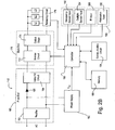
- Fig. 2B is a simplified block diagram of the digital electronic dimming ballast 110.
- the ballast 110 drives three fluorescent lamps L1, L2, L3 in parallel.
- Electronic ballasts typically can be analyzed as comprising a front end 160 and a back end 170.
- the front end 160 may include power factor correction means (not shown) so that the ballast 110 presents a predominantly resistive load to the line voltage means.
- the front end 160 typically includes a rectifier 162 for generating a rectified voltage from an alternating-current (AC) mains line voltage, and a filter circuit, for example, a valley-fill circuit 164, for filtering the rectified voltage to produce a direct-current (DC) bus voltage.
- AC alternating-current
- DC direct-current
- the valley-fill circuit 164 is coupled to the rectifier 162 through a diode 166 and includes one or more energy storage devices that selectively charge and discharge so as to fill the valleys between successive rectified voltage peaks to produce a substantially DC bus voltage.
- the DC bus voltage is the greater of either the rectified voltage or the voltage across the energy storage devices in the valley-fill circuit 164.
- the back end 170 typically includes an inverter 172 for converting the DC bus voltage to a high-frequency AC voltage and an output circuit 174 comprising a resonant tank circuit for coupling the high-frequency AC voltage to the lamp electrodes.
- a balancing circuit 176 is provided in series with the three lamps L1, L2, L3 to balance the currents through the lamps and to prevent any lamp from shining brighter or dimmer than the other lamps.
- the front end 160 and back end 170 of the ballast 110 are described in greater detail in commonly-assigned U.S. Patent No. 6,674,248, issued January 6, 2004 , entitled ELECTRONIC BALLAST, the entire disclosure of which is hereby incorporated by reference.
- a controller 180 generates drive signals to control the operation of the inverter 172 so as to provide a desired load current to the lamps L1, L2, L3.
- the controller 180 is operable to control the intensity of the lamps L1, L2, L3 from a low-end (i.e., determined by the low-end trim) to a high-end (i.e., determined by the high-end trim).
- the controller 180 is preferably implemented as a microcontroller, but may be any suitable processing device, such as a programmable logic device (PLD), a microprocessor, or an application specific integrated circuit (ASIC).
- PLD programmable logic device
- ASIC application specific integrated circuit
- the balancing circuit 176 is operable to provide a control signal to the controller 180 if one or more of the lamps L1, L2, L3 are missing or faulty.
- the balancing circuit 176 is described in greater detail in U.S. Patent Application No. 11/120,229, filed May 2, 2005 , entitled ELECTRONIC BALLAST HAVING MISSING LAMP DETECTION, the entire disclosure of which is hereby incorporated by reference.
- a power supply 182 is connected across the outputs of the rectifier 162 to provide a DC supply voltage, V CC , which is used to power the controller 180.
- a communication circuit 184 is coupled to the controller 180 and allows the controller 180 to communicate with the other ballasts 110 on the digital ballast communication link 120.
- the controller 180 is also coupled to a memory 186 for storage of the ballast factor and other ballast parameters, such as, for example, a link address of the ballast, the high-end trim, and the low-end trim.
- the memory 186 comprises an electrically erasable programmable read-only memory (“EEPROM").
- EEPROM electrically erasable programmable read-only memory
- the memory 186 may be locked and unlocked, which is a standard feature of EEPROMs.
- the ballast 110 further comprises a plurality of inputs 190 including an occupancy sensor input 192, a daylight sensor input 194, an IR input 196, and a wallstation input 198.
- the controller 180 is coupled to the plurality of inputs 190 such that the controller 180 is responsive to the occupancy sensor 140, the daylight sensor, the IR receiver 142, and the wallstation 144 of the lighting control system 100.
- the ballast 110 stores the ballast factor in the memory 186, such that the ballast factor can be configured in response to received user commands, e.g., from commands received via the communication circuit 184 (i.e., the digital ballast communication link 120) or via the IR input 196 (i.e., the IR receiver 142).
- the ballast factor of the ballast 110 is preferably "locked", such that the ballast factor is substantially prevented from being changed as will be described in greater detail below.
- the ballast 110 according to the present invention is operable to receive a ballast factor value and operate with the new ballast factor represented by the value.
- the ballast 110 is operable to receive a value that represents a ballast factor, even if the ballast 110 is already configured with a different ballast factor.
- the ballast 110 operates in connection therewith until, for example, the ballast is reconfigured and the ballast factor value is replaced by another one. This preferably occurs by flashing the memory 186, as known in the art.
- the ballast 110 is "locked” or otherwise substantially prevented from being updated with a new ballast factor unless particular steps are taken to reconfigure the ballast 110 preferably by authorized personnel. Since the ballast factor is stored in the memory 186, which is an electrically erasable programmable read-only memory, boot loading the ballast 110, as known in the art, will not reset or otherwise erase the ballast factor setting previously configured in the ballast 110. Further, and as described in greater detail below, the ability to change the 110 ballast factor of a ballast is preferably secured, for example, by password protection. Thus, configuring or reconfiguring the ballast 110 with a particular ballast factor is procedurally different than, for example, defining the high-end trim for the ballast 110.
- the ballast factor for the ballast 110 is predefined by the manufacturer of the ballast.
- the ballast 110 can, thereafter, receive a new ballast factor value to update the ballast factor for the ballast 110.
- the ability for the ballast factor of the ballast 110 to be modified is not implemented in a non-secure fashion, however, but instead is implemented in a control locking system and is otherwise invariant to the typical user.
- the ballast 110 is operable to be customized for particular lamps, for example for respective input currents or other internal parameters for the lamps that are defined by the lamps' respective manufacturers.
- a table of respective input currents is provided with the ballast 110, such as on a physical label placed on the ballast 110 and/or provided in a technical specification that is distributed with the ballast 110 or provided in an electronic format, such as posted on the Internet.
- the label or other documentation associated with the ballast 110 includes a table of input currents for one or more lamps and for a plurality of ballast factors.
- Fig. 2C illustrates two input current tables 202, 204 that each represent ballast input current levels for two respective lamps at three ballast factors (0.85, 1.0 and 1.17).
- Table 202 lists input currents for a fixture comprising a combination of two four-foot T8 lamps and a ballast. For example, at 120V, the fixture's input current is 580 milliamps ("mA") when the ballast factor of the ballast 110 is 1.0. In the case when the ballast factor is 1.17, then at 120V the fixture's input current is 660mA.
- the ballast factor affects power consumption.
- the present invention frees the lighting designers 12 from the prior art constraints, particularly in connection with limitations associated with the limited ballast factors that are offered by the ballast manufacturers 16.
- the lighting designers 12 can now submit and implement lighting designs that comply with building specifications, meet energy efficiency standards or the like, without sacrificing light output and without having to add or remove fixtures.
- the lighting designers 12 can now specify a particular ballast factor that supports the lighting design.
- Ballast manufacturers can now provide ballasts having specified ballast factors without having to fabricate custom ballasts that may be very expensive and difficult to replace.
- the present invention represents a vast improvement over prior art lighting design operations, in which lighting controls constrained by hardware limitations govern, at least in part, a particular lighting design.
- the present invention enables the reverse to occur, in which the lighting design governs, at least in part, the hardware requirements, including the ballast factor.
- the ballast 110 of the present invention supports virtually an unlimited number of custom lighting configurations because a preferred ballast factor can be specified by the lighting designer 12 (or other party) and programmed into the ballast 110, as described herein. Accordingly, the ballast 110 is preferably provided with documentation that identifies the ballast factor in connection with one or more lamps. As noted above, for example, a label is printed and adhered to the ballast 110 such that one installing or servicing the ballast 110 or corresponding lighting fixture can easily identify the ballast factor.
- the ballast 110 can be configured with a ballast factor at various times and by specially authorized and trained personnel.
- the field service personnel 30 may configure the ballast 110 to have a specific ballast factor after installation. The field service personnel 30 may then provide documentation that lists the respective ballast factor setting for each ballast 110.
- an OEM 18 may configure the ballast 110 with a respective ballast factor prior to shipping the configured ballast 110 to the customer 14 or other party.
- the ballast 110 may be configured with a respective ballast factor by the ballast manufacturer 16, such as at the warehouse 22.
- Fig. 3 is a flowchart of a business method S300 of providing a ballast 110 having a desired ballast factor according to the present invention.
- a lighting designer 12 generates lighting designs of the fluorescent lighting control system of the building 10 and requests the ballasts 110 that have the desired ballast factor. Accordingly, the customer 14 may order the ballasts having the desired ballast factor directly from the ballast manufacturer 16 or the OEM 18.
- the OEM 18 programs the ballast with the desired ballast factor and locks the ballast factor at step S306.
- the OEM 18 preferably need not stock more than one model of a ballast 110 since the ballast 110 can be configured with countless ballast factors.
- the ballast manufacturer 16 provides the OEM 18 with a tool (i.e., the ballast factor programmer 150) for programming the ballast with the desired ballast factor, e.g., using a programmer ballast factor adjustment procedure S400, which will be described in greater detail below with reference to Fig. 4B .
- the OEM 18 installs the ballasts 110 in the desired lighting fixtures, documents the ballast factor (e.g., on a label adhered to the ballast 110, in the documentation that accompanies the ballast 110, on the Internet, or any combination thereof), and ships the ballast 110 to the customer 14.
- the lighting fixture having the ballast 110 is installed in the building 10 by the electrical contractor 28 at step S310.
- the customer 14 does not order the ballast from the OEM 18 at step S304, then the customer orders the ballast directly from the ballast manufacturer 16. As with the OEM 18, the ballast manufacturer 16 need not stock more than one model of the ballast 110. If the ballast 110 should be programmed with the desired ballast factor by the ballast manufacturer 16 prior to shipment at step S312, the ballast manufacturer configures the ballasts 110 with the desired ballast factor and locks the ballast factor at step S314 (e.g., by executing the programmer ballast factor adjustment procedure S400 using the ballast factor programmer 150).
- the ballast manufacturer 16 documents the ballast factor (e.g., on a label adhered to the ballast 110, in documentation that accompanies the ballast 110, on the Internet, or any combination thereof) and ships the ballast 110 to the customer 14 at step S316.
- the customer 14 receives the ballast 110 and the electrical contractor 28 installs the ballast in the lighting fixture (that was provided by the OEM 18) at step S318.
- the ballast manufacturer 16 ships the ballast 110 without the ballast factor programmed (e.g., with a default ballast factor of 1.0) at step S320 and the ballast 110 is installed at the building 10 by the electrical contractor 28 at step S322.
- the field service personnel 30 of the ballast manufacturer 16 should at step S324 configure the ballast factor of the ballast 110 after the ballast is installed (at step 322), the field service personnel programs the ballast factor of the installed ballasts 110 at step S326.
- the field service personnel 30 may use the ballast factor programmer 150 with the programmer ballast factor adjustment procedure S400 to adjust the ballast factor of the ballast 110.
- the field service personnel 30 may use the GUI software running on the handheld remote control 148 (e.g., a PDA) to modify the ballast factor of the ballast 110 as part of a handheld remote control ballast adjustment procedure S500, which will be described in greater detail below with reference to Fig. 5 .
- the field service personnel 30 reviews technical documentation or information that is available and that discloses the ballast factor in order to determine the desired ballast factor. If the ballast 110 shipped at step S320 is replacing a previously-installed ballast of the fluorescent lighting control system of the building 10 (i.e., the shipped ballast is a replacement ballast), the field service personnel 30 may instruct the ballast 110 to automatically determine the ballast factor, for example, by using the handheld remote control ballast factor adjustment procedure S500. Accordingly, the ballast is operable to determine the ballast factor of the previously-installed ballast and to use this ballast factor as the ballast factor for the replacement ballast as will be described in greater detail below.
- the ballast factor value of the ballasts 110 is stored in the memory 186 of each of the ballasts and/or in a database in the link power supply 130. This ballast factor value is used to configure the ballast factor of the replacement ballast 110 with the appropriate ballast factor.
- the customer 14 programs the ballast factor of the ballasts 110 at step S328 using, for example, the handheld remote control ballast factor adjustment procedure S500, or alternatively, a "low-tech" programming method S600, which will be described in greater detail with reference to Fig. 6 .
- the ballast 110 is a replacement ballast, the customer 14 may instruct the ballast 110 to automatically determine the ballast factor.
- ballast manufacturer 16 and the OEM preferably use the ballast factor programmer 150 to program the ballast factor of the ballasts.
- the field service personnel 30 may use the ballast factor programmer 150 to simultaneously program the ballast factors of all of the ballasts 110 of the lighting control system 100 after the ballasts have been installed in the building 10.
- Fig. 4A is a simplified block diagram of the ballast factor programmer 150 according to the present invention.
- the ballast factor programmer 150 preferably includes a controller 410 for controlling the operation of the ballast factor programmer.
- the controller 410 is preferably implemented as a microcontroller, but may be any suitable processing device, such as a programmable logic device (PLD), a microprocessor, or an application specific integrated circuit (ASIC).
- PLD programmable logic device
- ASIC application specific integrated circuit
- the ballast factor programmer 150 also comprises a keypad 412 (e.g., a numeric keypad), which is coupled to the controller 410, such that the controller is operable to receive user inputs representative of the desired ballast factor.
- the keypad includes at least ten numeric buttons (representing the digits zero through nine), an enter button (to be pressed when the desired ballast factor has been entered using the numeric buttons), and a clear button (to clear the presently-entered ballast factor and start over).
- the controller 410 is also coupled to a visual display (e.g., two adjacent seven-segment displays) to display the desired ballast factor indicated by the inputs provided by the keypad 412.
- the controller 410 is operable to store the desired ballast factor in a memory 415 and to transmit the desired ballast factor as part of a digital signal across the digital ballast communication link 120 via a communication circuit 416.
- the ballast factor programmer 150 further comprises a power supply 418 operable to receive line voltage and generate a DC voltage V CC for powering the controller 410, and other parts of programmer 150.
- Fig. 4B is a flowchart of the programmer ballast factor adjustment procedure S400, which uses the ballast factor programmer 150 to adjust the ballast factor of the ballast 110 according to the present invention.
- the programmer ballast factor adjustment procedure S400 is typically executed by the ballast manufacturer 16 or the OEM 18 to program the ballast factor of the ballast 110 using the ballast factor programmer 150 prior to shipping the ballast to the customer 14, but may also be executed by the field service personnel 30 after the ballast is installed.
- the ballast 110 and the ballast factor programmer 150 are coupled to the digital ballast communication link 120 at step S420.
- the desired ballast factor is then entered using the keypad 412 of the ballast factor programmer 150 at step S422. If the correct ballast factor has not been entered at step S424, the clear button of the keypad 412 is pressed at step S426 and the desired ballast factor can be reentered at step S422. If the correct ballast factor has been entered at step S424, the enter button of the keypad 412 is pressed at step S428.
- the desired ballast factor that was entered at step S422 is stored in the memory 415 and is transmitted across the digital ballast communication link 120. Accordingly, the ballast 110 receives the digital message containing the desired ballast factor and stores the desired ballast factor in the memory 186, which will be described in greater detail below.
- Fig. 5 is a flowchart of the handheld remote control ballast factor adjustment procedure S500, which uses the handheld remote control 148 to adjust the ballast factor of the ballast 110 according to the present invention.
- the handheld remote control ballast factor adjustment procedure S500 is typically executed by the field service personnel 30 or the customer 14 after the ballasts 110 are installed in the building 10.
- the handheld remote control ballast factor adjustment procedure S500 is implemented using a graphical user interface (GUI) software provided on a PDA, e.g., the handheld remote control 148.
- GUI software may be provided on a personal computer (PC), which may be operatively coupled to the digital ballast communication link 120 as described in previously-referenced U.S. Provisional Patent Application No. 60/858,844 .
- step S502 the user enters a ballast factor programming mode ("BF-programming mode") using the GUI software running, for example, on the PDA.
- the GUI software prompts the user for a password and the user enters the password at step S504. If the password is incorrect at step S506, the user is able to enter the password again at step S504.
- the procedure S500 continues on and the user is able to decide at step S508 whether the ballast factor should be automatically determined (such as, for example, when the ballast 110 is a replacement ballast) or alternatively if the ballast factor should be manually entered. If the ballast 110 is a replacement ballast at step S508, the user selects "Replacement Ballast" using the GUI software at step S510. The user is then given the option to confirm that the ballast is a replacement ballast at step S512, i.e., the GUI software warns the user that the ballast factor is about to be changed.
- the user If the user does confirm that the ballast 110 is a replacement ballast at step S510, the user selects "Do Not Confirm” using the GUI software at step S514. If the user confirms that the ballast is a replacement ballast at step S510, the user selects "Confirm” using the GUI software at step S516 and the PDA transmits an IR signal containing a "replacement ballast” command to the ballast 110. Accordingly, the ballast 110 queries the link power supply 130 for the ballast factor and receives the ballast factor from the link power supply. The ballast 110 then stores and locks the ballast factor. Finally, the user exits the BF programming mode using the GUI software at step S518.
- ballast 110 is not a replacement ballast at step S508
- the user selects "Manually Enter Ballast Factor” using the GUI software at step S520 and then manually enters the desired ballast factor at step S522.
- the user is prompted to confirm that the entered ballast factor is correct at step S524, i.e., the GUI software provides a warning screen to inform the user that the ballast factor of the ballast 110 is about to be changed.
- the desired ballast factor is incorrect at step S524, the user may select "Clear” using the GUI software at step S526 and reenter the desired ballast factor at step S522.
- the user selects "Enter” using the GUI software at step S514 and the PDA transmits the desired ballast factor to the ballast 110 via the IR receiver 142. The user then exits the BF programming mode using the GUI software at step S518.
- Fig. 6 is a flowchart of the low-tech ballast factor adjustment procedure S600 for configuring the ballast factor of the ballast 110 in accordance with an alternative embodiment of the present invention.
- the ballast 110 is configured with a respective ballast factor without the aid of the ballast factor programmer 150 or the handheld remote control 148 (via the IR receiver 142).
- the low-tech ballast factor adjustment procedure S600 enables the ballast 110 to be configured with the desired ballast factor by controlling the intensity of the connected lamp to an intensity representative of the desired ballast factor and then cycling power to the lamp a predetermined number of times.
- the ballast 110 is adjusted to low-end, i.e., the lamp connected to the ballast is controlled to the minimum intensity.
- power is cycled to the ballast three times, i.e., power to the ballast is removed and then immediately restored three times.
- the ballast 110 is adjusted to high-end, i.e., the lamp connected to the ballast is controlled to the maximum intensity at step S606, and power is cycled to the ballast three times at step S608.
- the lamps are removed, and then reinserted to provide another level of security.
- the ballast 110 is ready to be configured with the desired ballast factor.
- the intensity of the lamp coupled to the ballast 110 is controlled to an intensity that represents the desired ballast factor at step S612, and power is cycled to the ballast three times at step S614.
- the ballast 110 programs the present intensity as the new ballast factor and flashes the lamp to signal that the new ballast factor has been accepted. For example, if the ballast factor is presently 1.0 and the ballast is controlled to 85% of the dimming range during step S612, the new ballast factor is 0.85 at step S614. Thereafter, the ballast 110 operates with the new ballast factor and is unchangeable again, until, for example, steps described in the flowchart shown in Fig. 6 are repeated.
- the low-tech ballast factor adjustment procedure S600 provides a plurality of levels of security in order to change the ballast factor of the ballast 110.
- the ballast 110 For the first and second levels of security, the ballast 110 must either be at low-end or high-end while power to the ballast is cycled three times.
- the lamps For the third level of security, the lamps must subsequently be removed and then reinstalled. Finally, power to the ballast 110 must be cycled three consecutive times again in order to program the new ballast factor.
- the low-tech ballast factor adjustment procedure S600 can only adjust the ballast factor of the ballast 110 to an intensity in the dimming range of the ballast, the low-tech ballast factor adjustment procedure S600 cannot increase the value of the ballast factor.
- Fig. 7 is a flowchart of a signal receiving procedure S700 executed by the controller 180 of the ballast 110 to adjust the ballast factor in accordance with a preferred embodiment of the present invention.
- the ballast 110 is configured electronically by receiving at step S702 a signal via the digital ballast communication link 120 (i.e., from the ballast factor programmer 150) or the infrared (IR) receiver 142 (i.e., from the handheld remote control 148).
- the received signal may contain the desired ballast factor to be stored in the memory 186 or a command to automatically determine the ballast factor from the database of ballast parameters stored in the link power supply 130, i.e., a "replacement ballast" command.
- the ballast 110 transmits a query message to the link power supply at step S706.
- the signal receiving procedure S700 waits until a response from the link power supply 130 is received at step S708, at which time the controller 180 determines at step S710 the desired ballast factor of the ballast 110 from the response message. If the controller 180 has not received a command to automatically determine the ballast factor at step S704, but the desired ballast factor is part of the received signal at step S712, the controller determines the desired ballast factor from the received signal at step S714.
- the controller 180 executes a secure memory storage procedure S800 to store the desired ballast factor in the memory 186. Thereafter, the ballast 110 operates with a new ballast factor and is unchangeable again, until, for example, steps described in the flowchart shown in Fig. 7 are repeated.
- Fig. 8 is a flowchart of the secure memory storage procedure S800.
- the controller 180 unlocks the memory 186 of the ballast 110.
- an Unlock-BF byte i.e., a specific value representing a "password” or special code required to unlock the ballast factor value in the memory 186) is stored in a specific memory location of the memory. For example, a "password" value of 0xFA (hexadecimal) may be stored in a specific memory location of 0xFF (hexadecimal).
- a determination is made at step S806 as to whether the value in the specific memory location is set to the value of the Unlock-BF byte.
- the secure memory storage procedure S800 simply exits. If the Unlock-BF byte is stored in the correct memory location at step S806, the ballast 110 is configured to receive a new ballast factor value. At step S808, the controller 180 stores the desired ballast factor in the memory 186. The controller 180 then clears the specific memory location (which was set to the Unlock-BF byte at step S804) at step S810 and locks the memory 186 at step S812.
- Figs. 9A and 9B are flowcharts of a start-up procedure S900 executed by the controller 180 of the ballast 110 to adjust the ballast factor as part of the low-tech ballast factor adjustment procedure S600 of Fig. 6 .
- the start-up procedure S900 begins at step S902 at start-up of the controller 180, i.e., when the controller is unpowered and then power is applied to the controller. Accordingly, whenever power is cycled to the ballast 110, e.g., during the low-tech ballast factor adjustment procedure S600, the start-up procedure S900 is executed before the controller 180 begins normal operation.
- the start-up procedure S900 uses a variable SEC_LVL to determine at which point in the low-tech ballast factor adjustment procedure S600 (i.e., at what level of security) that the ballast 110 is operating in. For example, the variable SEC_LVL is set to one (1) after power is cycled to the ballast 110 three times while the ballast is at low-end, i.e., after the first level of security.
- the start-up procedure S900 also uses a variable M to keep track of how many times that power to the ballast 110 is cycled during each level of security.
- the controller 180 operates to determine if power is cycled to the ballast 110 three times while the ballast is at low-end. Specifically, if the ballast 110 is at low-end at step S906, the variable M is incremented by one at step S908. If the variable M is equal to three (3) at step S910, the variable SEC_LVL is set to one (1) and the variable M is cleared at step S912. If the variable M is not equal to three (3) at step S910, the procedure S900 simply exits and the controller 180 begins normal operation. If the variable SEC_LVL is equal to zero (0) at step S904, but the ballast 110 is not at low-end at step S906, the variable M is cleared and the variable SEC_LVL is set to zero (0) at step S914.
- the controller 180 determines if the ballast is maintained at high-end while power is cycled three times. If the ballast 110 is at high-end at step S918, the variable M is incremented by one at step S920. If the variable M is equal to three (3) at step S922, the variable SEC_LVL is set to two (2) and the variable M is cleared at step S924. Otherwise, the procedure S900 simply exits. If the ballast 110 is not at high-end at step S918, the variable M is cleared and the variable SEC_LVL is set to zero (0) at step S926.
- variable SEC_LVL is not equal to zero (0) or one (1), but is equal to two (2) at step S928, the controller 180 now determines if the lamps are removed and then replaced before moving onto the next level of security.
- the controller 180 uses a variable LMP_OUT to keep track of when the lamps are removed. If the variable LMP_OUT is not set to TRUE at step S930 (i.e., the lamps have not been previously removed), a determination is made at step S932 as to whether the lamps are presently removed from the sockets of the lighting fixture. If so, the variable LMP_OUT is set to TRUE at step S934 and the procedure S900 exits. If the lamps are not removed at step S932, the variable SEC_LVL is set to zero (0) at step S935 and the procedure S900 exits.
- variable LMP_OUT is set to TRUE at step S930 (i.e., the lamps have been previously removed), but the lamps have not been replaced at step S936, the variable SEC_LVL is set to zero (0) at step S937 and the procedure S900 exits. However, when the lamps are replaced at step S936, the variable SEC_LVL is set to three (3) and the variable LMP_OUT is set to FALSE at step S938 and the procedure S900 exits.
- the controller 180 is ready to receive a new ballast factor. Accordingly, the user is able to adjust the intensity of the lamps coupled to the ballast 110 to an intensity representative of the desired ballast factor, and then cycle power to the ballast three times.
- the controller 180 uses a variable PRES_INT to store the present intensity of the lamps and a variable PREV_INT to store the previous intensity of the lamps, i.e., the intensity of the lamps the last time that power was cycled to the ballast 110.
- variable M is equal to zero (0) at step S942 (i.e., after the first time that the power is cycled to the ballast after the variable SEC_LVL is set to four), the variable PREV_INT is set equal to the variable PRES_INT at step S944 and the variable M is incremented at step S946. If the variable M is not equal to zero (0) at step S942, a determination is made at step S948 as to whether the variable PRES_INT is equal to the variable PREV_INT, i.e., whether the intensity of the lamp has changed since the last time that power was cycled to the ballast 110. If the intensity has changed at step S948, the variable M is cleared and the variable SEC_LVL is set to zero (0) at step S950 and the procedure S900 exits.
- the new ballast factor is stored in the memory 186 using the secure memory storage procedure S800 shown in Fig. 8 .
- the variable M is cleared and the variable SEC_LVL is set to zero (0) at step S958 and the procedure S900 exits.
- a ballast 110 having an adjusted or reconfigured ballast factor does not affect the performance or responsiveness of a lamp coupled to the ballast.
- a ballast 110 configured with a new ballast factor effectively re-scales the dimming range of the ballast.
- a ballast 110 that has a reconfigured ballast factor of 0.85 will provide up to 85% of the light output rated by the lamp manufacturer. Controlling a ballast 110 configured with a ballast factor of 0.85 to intensities between 0-100% will cause the lamp to illuminate from off to 85% of the rated output.
- the present invention preferably supports a plurality of business methods that are implemented, at least in part, as a function of the ballast 110.
- the ballast manufacturers 16 can work with lighting designers 12 to create a new method for lighting designs because, unlike in the prior art, a ballast factor can be ordered for ballasts 110. Further, a plurality of ballast factors can be ordered for a plurality of ballasts 110. The ballast manufacturer 16 can charge a fee to the lighting designer 12 and/or customer 14 for use of the new lighting design method.
- the lighting designer 12 can specify that only ballasts that have the ability to be configured with a respective ballast factor (such as the ballast 110) to be used in a particular building project. By placing this requirement on a particular lighting control system 100, the lighting designer may ensure that the lighting control system will perform as designed. From the point of view of the ballast manufacturer, the ballasts 110 can be sold at a premium price, particularly in view of the added functionality and flexibility that the ballast 110 provides.
- the ballast manufacturer 16 can charge fees for replacing ballasts 110, for example, via the field service personnel 30.
- the field service personnel 30 can use the present invention to determine a previous ballast's ballast factor setting, and configure a new ballast 110 with the previous ballast's ballast factor.
- new ballast factors can be provided either for currently installed or existing ballasts 110, or for new ballasts 110.
- a building 10 may be configured with new lighting fixtures that have substantially improved reflective properties. By providing improved reflective properties in, for example a fixture upgrade, a substantial reduction in power can be achieved without sacrificing the total light output of the fixture.
- the ballasts 110 can be reconfigured with a new ballast factor, or new ballasts 110 with a new ballast factor setting can be installed.
- the customers 14 will realize substantial power cost savings as a function of the new fixtures and new ballast factor, and will accordingly invest in service fees that are attributable to configuring the ballasts 110 with new ballast factors. Further, the customer 14 will realize reductions in energy costs by load shedding and will enjoy tax credits and other positive reinforcement measures received from a power company in connection with reductions in power consumption per square foot, per light fixture and per location.
- the OEM 18 has incentive to pay a premium to the ballast manufacturers 14 for ballasts 110 because the ballast operates to make the best use of the individual lighting fixture characteristics as a function of the adjustable ballast factor.
- the present invention relieves the OEM 18 from concerns of obtaining a ballast that has a suitable ballast factor for the lighting fixture.
- the OEM 18 configures the ballast 110 to support any ballast factor that is suitable and/or appropriate for the respective lighting fixture manufactured by the OEM 18.
- the OEM 18 may enter into one or more business partnerships with the ballast manufacturer 16 and the OEM 18 may charge the customer 14 a premium fee for service associated with the ballast 110.
- the OEM 18 will realize improved profitability in connection with the ballast 110, as customers will pay additional fees for lamp fixtures outfitted with ballast 110.
- the OEM 18 may elect to partner with the ballast manufacturer 16 by paying the ballast manufacturer a percentage of each ballast 110 sold in connection with a particular fixture, for all ballasts 110 sold in connection with any fixture, or some other arrangement.
- ballast 110 having an adjustable ballast factor provides numerous benefits over prior art ballasts.
- a single ballast 110 is operable to support virtually any kind of fixture or design for a particular lamp, and can be customized either prior to shipment or after shipment of the fixture.
- the lighting designers 12 can create new designs that can be implemented using the ballast 110 of the present invention without a need for ordering a plurality of prior art ballasts that have permanent and respective ballast factors.
- Energy codes that enforce limits, for example, on watts per square foot and total lighting wattage can be met as a function of the ballast factor of ballast 110 trimming down energy consumption. Further, energy credits and the like issued by power companies are attainable as a function of the adjustable ballast factor provided in connection with ballast 110.
- ballast 110 of the present invention preferably supports new business methods in which ballast 110 can be configured, for example, at the site where lighting fixtures are installed in a building for a fee. Furthermore, original equipment manufacturers can provide the ballast 110 of the present invention with a predefined and customized ballast factor for a particular building lighting design.
- the ballast 110 according to the present invention can be implemented in load types other than dimming fluorescent lamps.
- the present invention is applicable to non-dimming ballasts 110, light emitting diodes ("LEDs”), high-intensity discharge lighting (“HID”) or the like.
Landscapes
- Circuit Arrangement For Electric Light Sources In General (AREA)
- Discharge-Lamp Control Circuits And Pulse- Feed Circuits (AREA)
- Circuit Arrangements For Discharge Lamps (AREA)
Claims (25)
- Verfahren zum Konfigurieren eines Vorschaltfaktors eines dimmfähigen Vorschaltgeräts zur Regelung der Intensität einer Gasentladungslampe, wobei das Verfahren die folgende Schritte umfasst:Empfang eines elektronischen Eingabewertes, welcher einen gewünschten Vorschaltfaktor darstellt, durch einen Prozessor, wobei der gewünschte Vorschaltfaktor eine effektive maximale Lampenleistung für die Lampe darstellt, wenn diese durch das Vorschaltgerät betrieben wird, dividiert durch eine maximale Lampen-Nennleistung für die Lampe;Festlegen des gewünschten Vorschaltfaktors durch den Prozessor als Reaktion auf den elektronischen Eingabewert; undKonfigurieren des Vorschaltgeräts durch den Prozessor, um den gewünschten Vorschaltfaktor zu erhalten, wobei im Wesentlichen verhindert wird, dass der gewünschte Vorschaltfaktor nach dem Konfigurieren im Nachhinein verstellt wird,wobei der Prozessor ferner betriebsfähig ist, eine obere Grenzeinstellung für das Vorschaltgerät zu setzen, wobei die obere Grenzeinstellung eine gewünschte maximale Lichtintensität darstellt, auf welche die Lampe geregelt werden kann, wobei die gewünschte maximale Lichtintensität, wie von der oberen Grenzeinstellung festgelegt, höchstens gleich der effektiven maximalen Lampenleistung, wie vom gewünschten Vorschaltfaktor festgelegt, ist, und wobei ferner das Setzen der oberen Grenzeinstellung den gewünschten Vorschaltfaktor des Vorschaltgeräts nicht beeinflusst.
- Verfahren nach Anspruch 1, wobei der Schritt des Konfigurierens ferner die folgenden Schritte umfasst:Übertragung eines digitalen Signals an das Vorschaltgerät, wobei das digitale Signal den elektronischen Eingabewert einschließt;Festlegen des gewünschten Vorschaltfaktors durch den Prozessor als Reaktion auf das digitale Signal; undSpeichern des gewünschten Vorschaltfaktors in einem Speicher des Vorschaltgeräts.
- Verfahren nach Anspruch 1, wobei der Schritt des Konfigurierens ferner die Verwendung einer handgeführten Fernbedienung umfasst, um den elektronischen Eingabewert an den Prozessor zu übertragen.
- Verfahren nach Anspruch 1, ferner umfassend die folgenden Schritte:Koppeln eines installierten Vorschaltgeräts und einer zweiten Regelungsvorrichtung an eine digitale Kommunikationsverbindung;Aufbau einer Datenbank mit Parametern des installierten Vorschaltgeräts durch die zweite Regelungsvorrichtung;Entfernen des installierten Vorschaltgeräts;Installieren eines Ersatz-Vorschaltgeräts;Koppeln des Ersatz-Vorschaltgeräts an die digitale Kommunikationsverbindung;Übertragung eines Abfrage-Signals an die zweite Regelungsvorrichtung durch das Ersatz-Vorschaltgerät; undÜbertragung eines Vorschaltfaktors des installierten Vorschaltgeräts an das Ersatz-Vorschaltgerät durch die zweite Regelungsvorrichtung;wobei der Schritt des Speicherns ferner das Speichern des Vorschaltfaktors des installierten Vorschaltgeräts im Speicher des Ersatz-Vorschaltgeräts umfasst.
- Verfahren nach Anspruch 3, ferner umfassend die folgenden Schritte:Ausführen einer Software für eine grafische Benutzeroberfläche auf der handgeführten Fernbedienung; undVerwendung der Software für die grafische Benutzeroberfläche, um den elektronischen Eingabewert dem Prozessor einzugeben.
- Verfahren nach Anspruch 5, ferner umfassend den folgenden Schritt:Eingabe eines Passworts vor dem Schritt, in welchem die handgeführte Fernbedienung den elektronischen Eingabewert an den Prozessor überträgt.
- Verfahren nach Anspruch 3, wobei der Schritt des Festlegens ferner das Festlegen des gewünschten Vorschaltfaktors aus dem elektronischen Eingabewert, welcher durch die handgeführte Fernbedienung übertragen wurde, durch den Prozessor umfasst.
- Verfahren nach Anspruch 1, wobei der Schritt des Konfigurierens ferner die Verwendung einer Vorschaltfaktor-Programmiervorrichtung umfasst, um den gewünschten Vorschaltfaktor einzugeben, und der Schritt des Übertragens ferner das Übertragen des elektronischen Eingabewertes an den Prozessor durch die Vorschaltfaktor-Programmiervorrichtung umfasst.
- Verfahren nach Anspruch 8, ferner umfassend die folgenden Schritte:Verwendung eines Tastenfelds der Vorschaltfaktor-Programmiervorrichtung, um den gewünschten Vorschaltfaktor einzugeben;Übertragen eines digitalen Signals durch die Vorschaltfaktor-Programmiervorrichtung an das Vorschaltgerät, wobei das digitale Signal den elektronischen Eingabewert einschließt; undAnzeigen des gewünschten Vorschaltfaktors auf einer optischen Anzeige der Vorschaltfaktor-Programmiervorrichtung.
- Verfahren nach Anspruch 8, ferner umfassend den folgenden Schritt:Koppeln des Vorschaltgeräts und der Vorschaltfaktor-Programmiervorrichtung an eine digitale Kommunikationsverbindung;wobei der Schritt des Übertragens ferner das Übertragen des elektronischen Eingabewertes über die digitale Kommunikationsverbindung durch die Vorschaltfaktor-Programmiervorrichtung umfasst.
- Verfahren nach Anspruch 1, ferner umfassend die folgenden Schritte:Koppeln des Vorschaltgeräts an eine Gasentladungslampe;Regeln der Gasentladungslampe auf eine gewünschte Intensität;Festlegen des gewünschten Vorschaltfaktors als Reaktion auf die gewünschte Intensität; undBereitstellen des elektronischen Eingabewertes als eine Funktion des Festlegens des gewünschten Vorschaltfaktors.
- Verfahren nach Anspruch 11, ferner umfassend die folgenden Schritte:dem Vorschaltgerät signalisieren, den Vorschaltfaktor zu konfigurieren; unddas anschließende Speichern des gewünschten Vorschaltfaktors in einem Speicher des Vorschaltgeräts.
- Verfahren nach Anspruch 12, wobei der Schritt des Signalisierens ferner das wiederholte Aus- und Einschalten des Vorschaltgeräts für eine vorbestimmte Anzahl von Malen umfasst, nach dem Schritt der Regelung der Lampe auf eine erste Intensität.
- Verfahren nach Anspruch 13, ferner umfassend den folgenden Schritt:Bereitstellen einer Vielzahl von Sicherheitsstufen vor dem Schritt, in welchem dem Vorschaltgerät signalisiert wird, den Vorschaltfaktor zu konfigurieren.
- Verfahren nach Anspruch 14, wobei der Schritt des Bereitstellens einer Vielzahl von Sicherheitsstufen ferner die folgenden Schritte umfasst:Regeln der Lampe auf eine vorbestimmte Intensität; undanschließendes wiederholtes Aus- und Einschalten des Vorschaltgeräts für eine vorbestimmte Anzahl von Malen.
- Verfahren nach Anspruch 14, wobei der Schritt des Bereitstellens einer Vielzahl von Sicherheitsstufen ferner die folgenden Schritte umfasst:Trennen der Lampe vom Vorschaltgerät; undanschließendes Wiederverbinden der Lampe mit dem Vorschaltgerät.
- Verfahren nach Anspruch 13, wobei die vorbestimmte Anzahl von Malen drei beträgt.
- Elektronisches Vorschaltgerät, gekennzeichnet durch einen Vorschaltfaktor und betriebsfähig, eine Gasentladungslampe entsprechend dem Vorschaltfaktor zu betreiben, wobei das elektronische Vorschaltgerät umfasst:einen Eingang, ausgelegt, eine erste Vorschaltfaktor-Einstellung zu empfangen, welche einen ersten gewünschten Vorschaltfaktor für eine Kombination aus dem Vorschaltgerät und der Gasentladungslampe darstellt, wobei der erste gewünschte Vorschaltfaktor eine erste effektive maximale Lampenleistung für die Gasentladungslampe darstellt, wenn diese durch das Vorschaltgerät betrieben wird, dividiert durch eine maximale Lampen-Nennleistung für die Gasentladungslampe;einen Speicher, ausgelegt, die erste Vorschaltfaktor-Einstellung zu speichern; undeinen Prozessor, betriebsfähig, die erste Vorschaltfaktor-Einstellung, welche im Speicher gespeichert ist, zu verwenden, um das Vorschaltgerät zu veranlassen, den ersten gewünschten Vorschaltfaktor bereitzustellen, wenn das Vorschaltgerät die Lampe betreibt,wobei der Speicher ferner ausgelegt ist, einen oberen Grenzeinstellungswert für das Vorschaltgerät zu speichern, welcher eine gewünschte maximale Lichtintensität darstellt, auf welche die Gasentladungslampe geregelt werden kann, wobei die gewünschte maximale Lichtintensität, wie durch den oberen Grenzeinstellungswert festgelegt, höchstens gleich dem ersten gewünschten Vorschaltfaktor ist, und wobei ferner der Prozessor betriebsfähig ist, den oberen Grenzeinstellungswert, welcher im Speicher gespeichert ist, zu verwenden, um eine obere Grenzeinstellung des Vorschaltgeräts festzulegen, wobei jegliches Verstellen der oberen Grenzeinstellung den ersten gewünschten Vorschaltfaktor, welcher vom Vorschaltgerät bereitgestellt wird, nicht beeinflusst.
- Elektronisches Vorschaltgerät nach Anspruch 18, wobei der Eingang ein Datenkommunikationsanschluss ist, welcher Signale über eine Datenkommunikationsverbindung empfängt.
- Elektronisches Vorschaltgerät nach Anspruch 18, wobei der Eingang betriebsfähig ist, Infrarotsignale oder Funksignale zu empfangen.
- Elektronisches Vorschaltgerät nach Anspruch 18, wobei der Speicher ein elektronisch löschbarer, programmierbarer Nur-Lese-Speicher ist.
- Elektronisches Vorschaltgerät nach Anspruch 18, wobei der Eingang ausgelegt ist, eine zweite Vorschaltfaktor-Einstellung zu empfangen, welche einen zweiten gewünschten Vorschaltfaktor darstellt, wobei die zweite Vorschaltfaktor-Einstellung die erste Vorschaltfaktor-Einstellung im Speicher ersetzt, und wobei ferner der Prozessor die zweite Vorschaltfaktor-Einstellung, welche im Speicher abgelegt ist, verwendet, um das Vorschaltgerät zu veranlassen, den zweiten gewünschten Vorschaltfaktor bereitzustellen, wenn das Vorschaltgerät die Lampe betreibt oder wenn das Vorschaltgerät eine andere Lampe betreibt, und wobei ferner jegliches Verstellen des oberen Grenzeinstellungswertes den zweiten gewünschten Vorschaltfaktor, welcher vom Vorschaltgerät bereitgestellt wird, nicht beeinflusst.
- Elektronisches Vorschaltgerät nach Anspruch 18, wobei der erste gewünschte Vorschaltfaktor ein Verhältnis aus effektiver Lichtleistung der Kombination aus dem Vorschaltgerät und der Lampe zu der Nennleistung der Lampe repräsentiert, und wobei ferner das Verhältnis kleiner als, gleich oder größer als die Nennleistung der Lampe ist.
- Elektronisches Vorschaltgerät nach Anspruch 18, wobei das elektronische Vorschaltgerät ein dimmfähiges Vorschaltgerät ist.
- Elektronisches Vorschaltgerät nach Anspruch 18, wobei die Lampe eine Gasentladungslampe, eine Leuchtdiode oder eine Hochdruckentladungslampe ist.
Applications Claiming Priority (2)
| Application Number | Priority Date | Filing Date | Title |
|---|---|---|---|
| US11/733,093 US7880405B2 (en) | 2007-04-09 | 2007-04-09 | System and method for providing adjustable ballast factor |
| PCT/US2008/004571 WO2008124159A2 (en) | 2007-04-09 | 2008-04-08 | System and method for providing adjustable ballast factor |
Publications (2)
| Publication Number | Publication Date |
|---|---|
| EP2135489A2 EP2135489A2 (de) | 2009-12-23 |
| EP2135489B1 true EP2135489B1 (de) | 2013-06-12 |
Family
ID=39627769
Family Applications (1)
| Application Number | Title | Priority Date | Filing Date |
|---|---|---|---|
| EP08742675.5A Not-in-force EP2135489B1 (de) | 2007-04-09 | 2008-04-08 | System und verfahren zur bereitstellung eines einstellbaren vorschaltfaktors |
Country Status (6)
| Country | Link |
|---|---|
| US (1) | US7880405B2 (de) |
| EP (1) | EP2135489B1 (de) |
| CN (1) | CN102090147A (de) |
| CA (1) | CA2682936C (de) |
| MX (1) | MX2009010924A (de) |
| WO (1) | WO2008124159A2 (de) |
Families Citing this family (21)
| Publication number | Priority date | Publication date | Assignee | Title |
|---|---|---|---|---|
| TW200733811A (en) * | 2005-11-01 | 2007-09-01 | Koninkl Philips Electronics Nv | Configurable ballast |
| US20120235579A1 (en) | 2008-04-14 | 2012-09-20 | Digital Lumens, Incorporated | Methods, apparatus and systems for providing occupancy-based variable lighting |
| US10539311B2 (en) | 2008-04-14 | 2020-01-21 | Digital Lumens Incorporated | Sensor-based lighting methods, apparatus, and systems |
| US8866401B2 (en) * | 2009-03-06 | 2014-10-21 | Lutron Electronics Co., Inc. | Multi-stage power supply for a load control device having a low-power mode |
| US8680969B2 (en) * | 2009-03-20 | 2014-03-25 | Lutron Electronics Co., Inc. | Method of confirming that a control device complies with a predefined protocol standard |
| CN102835191A (zh) * | 2010-03-30 | 2012-12-19 | 马斯科公司 | 用于展示客户定义的照明规格并由此评价长久照明系统的装置、方法及系统 |
| DE102010003834A1 (de) * | 2010-04-09 | 2011-10-13 | Tridonic Gmbh & Co. Kg | Betriebsgerät für Leuchtmittel zum Ermitteln eines Energie- oder Leistungsverbrauchs und Verfahren zum Erfassen desselbigen |
| CA2816978C (en) | 2010-11-04 | 2020-07-28 | Digital Lumens Incorporated | Method, apparatus, and system for occupancy sensing |
| EP2774459B1 (de) | 2011-11-03 | 2021-01-06 | Digital Lumens Incorporated | Verfahren, systeme und vorrichtung für intelligente beleuchtung |
| CN106937459B (zh) | 2012-03-19 | 2020-06-16 | 数字照明股份有限公司 | 用于提供可变照明的方法、系统和设备 |
| US8836240B2 (en) * | 2012-06-30 | 2014-09-16 | Osram Sylvania Inc. | Dim mode start for electrodeless lamp ballast |
| US9232607B2 (en) | 2012-10-23 | 2016-01-05 | Lutron Electronics Co., Inc. | Gas discharge lamp ballast with reconfigurable filament voltage |
| JP6231133B2 (ja) * | 2013-01-25 | 2017-11-15 | フィリップス ライティング ホールディング ビー ヴィ | 照明装置及び照明システム |
| AU2014259974B2 (en) | 2013-04-30 | 2018-04-19 | Digital Lumens, Incorporated | Operating light emitting diodes at low temperature |
| EP3056068B1 (de) | 2013-10-10 | 2020-09-09 | Digital Lumens Incorporated | Verfahren, systeme und vorrichtung für intelligente beleuchtung |
| CN104582214A (zh) * | 2013-10-23 | 2015-04-29 | 苏州市纽克斯照明有限公司 | 一种数码led数字镇流器 |
| US9307621B1 (en) * | 2014-12-08 | 2016-04-05 | Cisco Technology, Inc. | Networked lighting management |
| RU2707177C2 (ru) | 2015-02-13 | 2019-11-25 | Филипс Лайтинг Холдинг Б.В. | Устройство для генерации света, запитываемое через балласт |
| CN105467874A (zh) * | 2015-11-30 | 2016-04-06 | 小米科技有限责任公司 | 智能插座上电子设备类别的识别方法及装置 |
| DE102016002963A1 (de) * | 2016-03-13 | 2017-09-14 | Bag Electronics Gmbh | Hochfunktionales Betriebsgerät |
| GB2643920A (en) * | 2024-09-07 | 2026-03-11 | Innerscene Ltd | Optical display device |
Family Cites Families (14)
| Publication number | Priority date | Publication date | Assignee | Title |
|---|---|---|---|---|
| US5872429A (en) | 1995-03-31 | 1999-02-16 | Philips Electronics North America Corporation | Coded communication system and method for controlling an electric lamp |
| US5798617A (en) | 1996-12-18 | 1998-08-25 | Pacific Scientific Company | Magnetic feedback ballast circuit for fluorescent lamp |
| US6963178B1 (en) * | 1998-12-07 | 2005-11-08 | Systel Development And Industries Ltd. | Apparatus for controlling operation of gas discharge devices |
| US6639369B2 (en) | 2001-03-22 | 2003-10-28 | International Rectifier Corporation | Electronic dimmable ballast for high intensity discharge lamp |
| US7304439B2 (en) | 2001-09-06 | 2007-12-04 | E. Energy Technology Limited | Phase-controlled dimmable electronic ballasts for fluorescent lamps with very wide dimming range |
| US7224125B2 (en) * | 2002-10-04 | 2007-05-29 | International Rectifier Corporation | Dimmable fluorescent lamp package |
| US6817732B1 (en) | 2002-12-05 | 2004-11-16 | Genlyte Thomas Group Llc | Efficiency fluorescent lighting system |
| US6900765B2 (en) * | 2003-07-23 | 2005-05-31 | The Boeing Company | Method and apparatus for forming millimeter wave phased array antenna |
| US6969955B2 (en) | 2004-01-29 | 2005-11-29 | Axis Technologies, Inc. | Method and apparatus for dimming control of electronic ballasts |
| US7619539B2 (en) | 2004-02-13 | 2009-11-17 | Lutron Electronics Co., Inc. | Multiple-input electronic ballast with processor |
| US7049768B1 (en) | 2004-11-24 | 2006-05-23 | Matsushita Electric Works Ltd. | High intensity discharge lamps with electronic control of dimming |
| US7369060B2 (en) * | 2004-12-14 | 2008-05-06 | Lutron Electronics Co., Inc. | Distributed intelligence ballast system and extended lighting control protocol |
| EP1689212B1 (de) | 2005-02-02 | 2008-01-23 | Patent-Treuhand-Gesellschaft für elektrische Glühlampen mbH | Verfahren und Anordnung zum Dimmen von Lichtquellen |
| US7575338B1 (en) * | 2005-10-03 | 2009-08-18 | Orion Energy Systems, Inc. | Modular light fixture with power pack |
-
2007
- 2007-04-09 US US11/733,093 patent/US7880405B2/en not_active Expired - Fee Related
-
2008
- 2008-04-08 MX MX2009010924A patent/MX2009010924A/es active IP Right Grant
- 2008-04-08 CA CA2682936A patent/CA2682936C/en active Active
- 2008-04-08 EP EP08742675.5A patent/EP2135489B1/de not_active Not-in-force
- 2008-04-08 CN CN2008800194921A patent/CN102090147A/zh active Pending
- 2008-04-08 WO PCT/US2008/004571 patent/WO2008124159A2/en not_active Ceased
Also Published As
| Publication number | Publication date |
|---|---|
| WO2008124159A2 (en) | 2008-10-16 |
| CA2682936A1 (en) | 2008-10-16 |
| US7880405B2 (en) | 2011-02-01 |
| MX2009010924A (es) | 2009-11-26 |
| CA2682936C (en) | 2014-01-28 |
| CN102090147A (zh) | 2011-06-08 |
| EP2135489A2 (de) | 2009-12-23 |
| US20080246415A1 (en) | 2008-10-09 |
| WO2008124159A3 (en) | 2008-12-11 |
Similar Documents
| Publication | Publication Date | Title |
|---|---|---|
| EP2135489B1 (de) | System und verfahren zur bereitstellung eines einstellbaren vorschaltfaktors | |
| CA2595949C (en) | Handheld programmer for lighting control system | |
| US7109668B2 (en) | Electronic lighting ballast | |
| US20090315400A1 (en) | Method of load shedding to reduce the total power consumption of a load control system | |
| US9161406B2 (en) | LED driver and lighting application for wattage control | |
| CN101558687A (zh) | 降低负载控制系统的总功耗的卸负载方法 | |
| US20140111111A1 (en) | Gas discharge lamp ballast with reconfigurable filament voltage | |
| JP2004247273A (ja) | 調光システム | |
| CN1939099A (zh) | 具有可编程或可配置控制单元的照明装置所用的电子镇流器或操控设备 | |
| US7474059B1 (en) | Fluorescent ballast with fiber optic and IR control | |
| TWM519868U (zh) | 分佈式調光控制式隨插即用自律式led層板燈 | |
| NL2005972C2 (en) | Led driver and lighting application for wattage control. | |
| HK1131717A (en) | Method of load shedding to reduce the total power consumption of a load control system | |
| HK1123437A (en) | Handheld programmer for lighting control system |
Legal Events
| Date | Code | Title | Description |
|---|---|---|---|
| PUAI | Public reference made under article 153(3) epc to a published international application that has entered the european phase |
Free format text: ORIGINAL CODE: 0009012 |
|
| 17P | Request for examination filed |
Effective date: 20091006 |
|
| AK | Designated contracting states |
Kind code of ref document: A2 Designated state(s): AT BE BG CH CY CZ DE DK EE ES FI FR GB GR HR HU IE IS IT LI LT LU LV MC MT NL NO PL PT RO SE SI SK TR |
|
| 17Q | First examination report despatched |
Effective date: 20120502 |
|
| DAX | Request for extension of the european patent (deleted) | ||
| GRAP | Despatch of communication of intention to grant a patent |
Free format text: ORIGINAL CODE: EPIDOSNIGR1 |
|
| RIC1 | Information provided on ipc code assigned before grant |
Ipc: H05B 41/36 20060101ALI20121210BHEP Ipc: H05B 37/02 20060101AFI20121210BHEP |
|
| GRAS | Grant fee paid |
Free format text: ORIGINAL CODE: EPIDOSNIGR3 |
|
| GRAA | (expected) grant |
Free format text: ORIGINAL CODE: 0009210 |
|
| AK | Designated contracting states |
Kind code of ref document: B1 Designated state(s): AT BE BG CH CY CZ DE DK EE ES FI FR GB GR HR HU IE IS IT LI LT LU LV MC MT NL NO PL PT RO SE SI SK TR |
|
| REG | Reference to a national code |
Ref country code: GB Ref legal event code: FG4D |
|
| REG | Reference to a national code |
Ref country code: CH Ref legal event code: EP |
|
| REG | Reference to a national code |
Ref country code: AT Ref legal event code: REF Ref document number: 617107 Country of ref document: AT Kind code of ref document: T Effective date: 20130615 |
|
| REG | Reference to a national code |
Ref country code: IE Ref legal event code: FG4D |
|
| REG | Reference to a national code |
Ref country code: DE Ref legal event code: R096 Ref document number: 602008025290 Country of ref document: DE Effective date: 20130808 |
|
| PG25 | Lapsed in a contracting state [announced via postgrant information from national office to epo] |
Ref country code: ES Free format text: LAPSE BECAUSE OF FAILURE TO SUBMIT A TRANSLATION OF THE DESCRIPTION OR TO PAY THE FEE WITHIN THE PRESCRIBED TIME-LIMIT Effective date: 20130923 Ref country code: SI Free format text: LAPSE BECAUSE OF FAILURE TO SUBMIT A TRANSLATION OF THE DESCRIPTION OR TO PAY THE FEE WITHIN THE PRESCRIBED TIME-LIMIT Effective date: 20130612 Ref country code: LT Free format text: LAPSE BECAUSE OF FAILURE TO SUBMIT A TRANSLATION OF THE DESCRIPTION OR TO PAY THE FEE WITHIN THE PRESCRIBED TIME-LIMIT Effective date: 20130612 Ref country code: FI Free format text: LAPSE BECAUSE OF FAILURE TO SUBMIT A TRANSLATION OF THE DESCRIPTION OR TO PAY THE FEE WITHIN THE PRESCRIBED TIME-LIMIT Effective date: 20130612 Ref country code: NO Free format text: LAPSE BECAUSE OF FAILURE TO SUBMIT A TRANSLATION OF THE DESCRIPTION OR TO PAY THE FEE WITHIN THE PRESCRIBED TIME-LIMIT Effective date: 20130912 Ref country code: GR Free format text: LAPSE BECAUSE OF FAILURE TO SUBMIT A TRANSLATION OF THE DESCRIPTION OR TO PAY THE FEE WITHIN THE PRESCRIBED TIME-LIMIT Effective date: 20130913 Ref country code: SE Free format text: LAPSE BECAUSE OF FAILURE TO SUBMIT A TRANSLATION OF THE DESCRIPTION OR TO PAY THE FEE WITHIN THE PRESCRIBED TIME-LIMIT Effective date: 20130612 |
|
| REG | Reference to a national code |
Ref country code: AT Ref legal event code: MK05 Ref document number: 617107 Country of ref document: AT Kind code of ref document: T Effective date: 20130612 |
|
| REG | Reference to a national code |
Ref country code: NL Ref legal event code: VDEP Effective date: 20130612 |
|
| REG | Reference to a national code |
Ref country code: LT Ref legal event code: MG4D |
|
| PG25 | Lapsed in a contracting state [announced via postgrant information from national office to epo] |
Ref country code: BG Free format text: LAPSE BECAUSE OF FAILURE TO SUBMIT A TRANSLATION OF THE DESCRIPTION OR TO PAY THE FEE WITHIN THE PRESCRIBED TIME-LIMIT Effective date: 20130912 Ref country code: HR Free format text: LAPSE BECAUSE OF FAILURE TO SUBMIT A TRANSLATION OF THE DESCRIPTION OR TO PAY THE FEE WITHIN THE PRESCRIBED TIME-LIMIT Effective date: 20130612 |
|
| PG25 | Lapsed in a contracting state [announced via postgrant information from national office to epo] |
Ref country code: LV Free format text: LAPSE BECAUSE OF FAILURE TO SUBMIT A TRANSLATION OF THE DESCRIPTION OR TO PAY THE FEE WITHIN THE PRESCRIBED TIME-LIMIT Effective date: 20130612 |
|
| PG25 | Lapsed in a contracting state [announced via postgrant information from national office to epo] |
Ref country code: CZ Free format text: LAPSE BECAUSE OF FAILURE TO SUBMIT A TRANSLATION OF THE DESCRIPTION OR TO PAY THE FEE WITHIN THE PRESCRIBED TIME-LIMIT Effective date: 20130612 Ref country code: SK Free format text: LAPSE BECAUSE OF FAILURE TO SUBMIT A TRANSLATION OF THE DESCRIPTION OR TO PAY THE FEE WITHIN THE PRESCRIBED TIME-LIMIT Effective date: 20130612 Ref country code: PT Free format text: LAPSE BECAUSE OF FAILURE TO SUBMIT A TRANSLATION OF THE DESCRIPTION OR TO PAY THE FEE WITHIN THE PRESCRIBED TIME-LIMIT Effective date: 20131014 Ref country code: AT Free format text: LAPSE BECAUSE OF FAILURE TO SUBMIT A TRANSLATION OF THE DESCRIPTION OR TO PAY THE FEE WITHIN THE PRESCRIBED TIME-LIMIT Effective date: 20130612 Ref country code: EE Free format text: LAPSE BECAUSE OF FAILURE TO SUBMIT A TRANSLATION OF THE DESCRIPTION OR TO PAY THE FEE WITHIN THE PRESCRIBED TIME-LIMIT Effective date: 20130612 Ref country code: IS Free format text: LAPSE BECAUSE OF FAILURE TO SUBMIT A TRANSLATION OF THE DESCRIPTION OR TO PAY THE FEE WITHIN THE PRESCRIBED TIME-LIMIT Effective date: 20131012 Ref country code: BE Free format text: LAPSE BECAUSE OF FAILURE TO SUBMIT A TRANSLATION OF THE DESCRIPTION OR TO PAY THE FEE WITHIN THE PRESCRIBED TIME-LIMIT Effective date: 20130612 |
|
| PG25 | Lapsed in a contracting state [announced via postgrant information from national office to epo] |
Ref country code: NL Free format text: LAPSE BECAUSE OF FAILURE TO SUBMIT A TRANSLATION OF THE DESCRIPTION OR TO PAY THE FEE WITHIN THE PRESCRIBED TIME-LIMIT Effective date: 20130612 Ref country code: RO Free format text: LAPSE BECAUSE OF FAILURE TO SUBMIT A TRANSLATION OF THE DESCRIPTION OR TO PAY THE FEE WITHIN THE PRESCRIBED TIME-LIMIT Effective date: 20130612 Ref country code: PL Free format text: LAPSE BECAUSE OF FAILURE TO SUBMIT A TRANSLATION OF THE DESCRIPTION OR TO PAY THE FEE WITHIN THE PRESCRIBED TIME-LIMIT Effective date: 20130612 |
|
| PLBE | No opposition filed within time limit |
Free format text: ORIGINAL CODE: 0009261 |
|
| STAA | Information on the status of an ep patent application or granted ep patent |
Free format text: STATUS: NO OPPOSITION FILED WITHIN TIME LIMIT |
|
| PG25 | Lapsed in a contracting state [announced via postgrant information from national office to epo] |
Ref country code: DK Free format text: LAPSE BECAUSE OF FAILURE TO SUBMIT A TRANSLATION OF THE DESCRIPTION OR TO PAY THE FEE WITHIN THE PRESCRIBED TIME-LIMIT Effective date: 20130612 |
|
| 26N | No opposition filed |
Effective date: 20140313 |
|
| PG25 | Lapsed in a contracting state [announced via postgrant information from national office to epo] |
Ref country code: IT Free format text: LAPSE BECAUSE OF FAILURE TO SUBMIT A TRANSLATION OF THE DESCRIPTION OR TO PAY THE FEE WITHIN THE PRESCRIBED TIME-LIMIT Effective date: 20130612 |
|
| REG | Reference to a national code |
Ref country code: DE Ref legal event code: R097 Ref document number: 602008025290 Country of ref document: DE Effective date: 20140313 |
|
| PG25 | Lapsed in a contracting state [announced via postgrant information from national office to epo] |
Ref country code: LU Free format text: LAPSE BECAUSE OF FAILURE TO SUBMIT A TRANSLATION OF THE DESCRIPTION OR TO PAY THE FEE WITHIN THE PRESCRIBED TIME-LIMIT Effective date: 20140408 Ref country code: MC Free format text: LAPSE BECAUSE OF FAILURE TO SUBMIT A TRANSLATION OF THE DESCRIPTION OR TO PAY THE FEE WITHIN THE PRESCRIBED TIME-LIMIT Effective date: 20130612 |
|
| REG | Reference to a national code |
Ref country code: CH Ref legal event code: PL |
|
| REG | Reference to a national code |
Ref country code: IE Ref legal event code: MM4A |
|
| PG25 | Lapsed in a contracting state [announced via postgrant information from national office to epo] |
Ref country code: LI Free format text: LAPSE BECAUSE OF NON-PAYMENT OF DUE FEES Effective date: 20140430 Ref country code: CH Free format text: LAPSE BECAUSE OF NON-PAYMENT OF DUE FEES Effective date: 20140430 |
|
| PG25 | Lapsed in a contracting state [announced via postgrant information from national office to epo] |
Ref country code: IE Free format text: LAPSE BECAUSE OF NON-PAYMENT OF DUE FEES Effective date: 20140408 |
|
| PG25 | Lapsed in a contracting state [announced via postgrant information from national office to epo] |
Ref country code: MT Free format text: LAPSE BECAUSE OF FAILURE TO SUBMIT A TRANSLATION OF THE DESCRIPTION OR TO PAY THE FEE WITHIN THE PRESCRIBED TIME-LIMIT Effective date: 20130612 |
|
| REG | Reference to a national code |
Ref country code: FR Ref legal event code: PLFP Year of fee payment: 9 |
|
| PG25 | Lapsed in a contracting state [announced via postgrant information from national office to epo] |
Ref country code: CY Free format text: LAPSE BECAUSE OF FAILURE TO SUBMIT A TRANSLATION OF THE DESCRIPTION OR TO PAY THE FEE WITHIN THE PRESCRIBED TIME-LIMIT Effective date: 20130612 |
|
| PG25 | Lapsed in a contracting state [announced via postgrant information from national office to epo] |
Ref country code: HU Free format text: LAPSE BECAUSE OF FAILURE TO SUBMIT A TRANSLATION OF THE DESCRIPTION OR TO PAY THE FEE WITHIN THE PRESCRIBED TIME-LIMIT; INVALID AB INITIO Effective date: 20080408 Ref country code: TR Free format text: LAPSE BECAUSE OF FAILURE TO SUBMIT A TRANSLATION OF THE DESCRIPTION OR TO PAY THE FEE WITHIN THE PRESCRIBED TIME-LIMIT Effective date: 20130612 |
|
| REG | Reference to a national code |
Ref country code: FR Ref legal event code: PLFP Year of fee payment: 10 |
|
| REG | Reference to a national code |
Ref country code: FR Ref legal event code: PLFP Year of fee payment: 11 |
|
| PGFP | Annual fee paid to national office [announced via postgrant information from national office to epo] |
Ref country code: GB Payment date: 20220325 Year of fee payment: 15 |
|
| PGFP | Annual fee paid to national office [announced via postgrant information from national office to epo] |
Ref country code: DE Payment date: 20220318 Year of fee payment: 15 |
|
| P01 | Opt-out of the competence of the unified patent court (upc) registered |
Effective date: 20230529 |
|
| PGFP | Annual fee paid to national office [announced via postgrant information from national office to epo] |
Ref country code: FR Payment date: 20230524 Year of fee payment: 16 |
|
| REG | Reference to a national code |
Ref country code: DE Ref legal event code: R119 Ref document number: 602008025290 Country of ref document: DE |
|
| GBPC | Gb: european patent ceased through non-payment of renewal fee |
Effective date: 20230408 |
|
| PG25 | Lapsed in a contracting state [announced via postgrant information from national office to epo] |
Ref country code: GB Free format text: LAPSE BECAUSE OF NON-PAYMENT OF DUE FEES Effective date: 20230408 |
|
| PG25 | Lapsed in a contracting state [announced via postgrant information from national office to epo] |
Ref country code: GB Free format text: LAPSE BECAUSE OF NON-PAYMENT OF DUE FEES Effective date: 20230408 Ref country code: DE Free format text: LAPSE BECAUSE OF NON-PAYMENT OF DUE FEES Effective date: 20231103 |
|
| PG25 | Lapsed in a contracting state [announced via postgrant information from national office to epo] |
Ref country code: FR Free format text: LAPSE BECAUSE OF NON-PAYMENT OF DUE FEES Effective date: 20240430 |
|
| PG25 | Lapsed in a contracting state [announced via postgrant information from national office to epo] |
Ref country code: FR Free format text: LAPSE BECAUSE OF NON-PAYMENT OF DUE FEES Effective date: 20240430 |