EP2135471B1 - Procédé et système s'appliquant à un transfert cellulaire interne e-utran - Google Patents
Procédé et système s'appliquant à un transfert cellulaire interne e-utran Download PDFInfo
- Publication number
- EP2135471B1 EP2135471B1 EP07709465A EP07709465A EP2135471B1 EP 2135471 B1 EP2135471 B1 EP 2135471B1 EP 07709465 A EP07709465 A EP 07709465A EP 07709465 A EP07709465 A EP 07709465A EP 2135471 B1 EP2135471 B1 EP 2135471B1
- Authority
- EP
- European Patent Office
- Prior art keywords
- enodeb
- upe
- plane node
- user plane
- tunnel
- Prior art date
- Legal status (The legal status is an assumption and is not a legal conclusion. Google has not performed a legal analysis and makes no representation as to the accuracy of the status listed.)
- Not-in-force
Links
Images


Classifications
-
- H—ELECTRICITY
- H04—ELECTRIC COMMUNICATION TECHNIQUE
- H04W—WIRELESS COMMUNICATION NETWORKS
- H04W36/00—Hand-off or reselection arrangements
- H04W36/02—Buffering or recovering information during reselection ; Modification of the traffic flow during hand-off
-
- H—ELECTRICITY
- H04—ELECTRIC COMMUNICATION TECHNIQUE
- H04W—WIRELESS COMMUNICATION NETWORKS
- H04W92/00—Interfaces specially adapted for wireless communication networks
- H04W92/16—Interfaces between hierarchically similar devices
- H04W92/20—Interfaces between hierarchically similar devices between access points
Definitions
- the invention refers to a handover method for a data packet based wireless mobile communications network and a system arranged to handle such a method.
- the network comprises a core network, CN, and a radio area network, RAN.
- the core network, CN comprises a control plane node, MME, intercommunicating with a user plane node, UPE.
- the radio area network comprises a mobile user equipment, UE, intercommunicating with an expanded source radio base transceiver station, source eNodeB. Payload data between the user equipment UE and the core network, CN, in the form of uplink, UL, data and downlink, DL, data is routed via a tunnel between the user plane node, UPE, and the source eNodeB.
- 3GPP LTE Long Term Evolution
- UMTS Universal Mobile Telecommunications System
- Some goals for the LTE project is to get improved efficiency, lower costs, improve services, make use of new spectrum opportunities, and better integration with other open standards.
- the LTE includes mostly or wholly extensions and modifications of the UMTS system.
- a Radio Network Controller (hereinafter called RNC) in legacy of UMTS Terrestrial Radio Access Network (hereinafter called UTRAN) has been distributed to the enhanced radio base station (hereinafter called eNodeB) and the functional entities of the core network, CN.
- RNC Radio Network Controller
- UTRAN UMTS Terrestrial Radio Access Network
- eNodeB enhanced radio base station
- CN CN
- One functional entity is a Mobility Management Entity (hereinafter called MME or control plane node) which is a control plane node arranged to handle reliable control signaling from the eNodeB to another functional entity being a User Plane Entity (hereinafter called UPE or user plane node).
- MME Mobility Management Entity
- UPE User Plane Entity
- the UPE is a user plane node handling unreliable signaling comprising payload data from the eNodeB to the UPE.
- NodeB is a term used in UMTS to denote the BTS (base transceiver station) controlling a cell in a cellular network.
- BTS base transceiver station
- Node B uses WCDMA as air transport technology.
- Node B contains radio frequency transmitter(s) and the receiver(s) used to communicate directly with the mobiles, which move freely around it. In this type of cellular networks the mobiles cannot communicate directly with each other but have to communicate with the BTSs.
- the eNodeB is an expanded NodeB arranged to handle wireless data communication that uses Orthogonal Frequency Division Multiple Access OFDMA as air transport technology.
- the OFDMA is arranged to replace the old CDMA and TDMA based systems.
- Each eNOdeB in the cellular network controls a cell in which the user equipment is positioned. When the user equipment moves from one cell to an adjacent cell a handover has to be performed where the communication path is directed from the previous NodeB (hereinafter referred to as source eNodeB) and the eNodeB (hereinafter referred to as target eNodeB) controlling the adjacent cell.
- source eNodeB the previous NodeB
- target eNodeB eNodeB
- the MME share similarities with control plane of the Serving General Packet Radio Service (hereinafter called GPRS) Support Node (hereinafter called SGSN) in the current release of the 3GPP core network.
- GPRS General Packet Radio Service
- SGSN Serving General Packet Radio Service Support Node
- the UPE terminates the RAN interface and is in that respect similar to the previously used Gateway Support Node (hereinafter called GGSN) when direct tunnel between the RNC and the GGSN is used.
- the System Architectur Evolution Gateway (SAE GW) is a node that will contain the main features of the GGSN in current release of the 3GPP network.
- RAN Radio Access Network
- eNodeBs communicating directly with the core network nodes MME and UPE.
- This effect is further enhanced when pooling of CN nodes (similar to lu-flex in the legacy 3GPP standard) is applied because an even larger number of eNodeBs will communicate with each MME and UPE.
- the cells of LTE radio are expected to be smaller than in legacy 3GPP radio and a moving UE is likely to cause a higher frequency of cell changes.
- the smaller cells also cause a shorter timing window for a signalling procedure to complete when dealing with a moving UE.
- the most basic procedure that needs to be functional at these constraints is the intra LTE handover when the UE moves from the control of one eNodeB to the control of another eNodeB.
- the increase in the expected number of eNodeBs and the expected reduction of coverage area per eNodeB will result in a substantially larger number of executed handover procedures between eNodeBs as well as between eNodeB and MME and UPE nodes.
- the hand-over procedure therefore need to be efficient to meet requirements of expected characteristics in end-to-end communication between UEs and applications located within or beyond the core network.
- Tunnel movement signalling between eNB and UPE Motorola, 3GPP TSG SA WG2 ARCHITECTURE - SAE, S2-0643052 , XP003018671
- a handover It is discussed whether the hand-over - the tunnel set up and movement - should be mediated by an MME or not.
- signalling between the UPE and an eNB, parallel to an existing tunnel is made for tunnel set up and movement.
- the object of the invention is to find a method and a system for a fast, efficient and reliable handover procedure for a data packet based cellular wireless mobile communications network.
- the communication network comprises a core network, CN, and a radio area network, RAN.
- the core network, CN comprises a control plane node, MME, intercommunicating with a user plane node, UPE.
- the radio area network comprises a mobile user equipment, UE, intercommunicating with an expanded source radio base transceiver station, source eNodeB. Payload data between the user equipment UE and the core network, CN, in the form of uplink, UL, data and downlink, DL, data is routed via a tunnel between the user plane node, UPE, and the source eNodeB.
- the handover comprises the step of establishing a temporary tunnel between the user plane node, UPE, and a target eNodeB.
- the handover is initiated by the target eNodeB transmitting unreliable uplink data signal to the UPE comprising information that a handover is about to take place and that the tunnel shall be moved from the source eNOdeB to the target eNodeB.
- tunnel refers to a situation where both uplink and downlink traffic are allowed between two endpoints.
- the endpoints are the UPE and the eNodeB.
- unreliable refers to a situation where a signal is transmitted from a first unit to a second unit without guaranteeing the delivery of the signal. This can be done by allowing the first unit to transmit a signal without any requirements on the second unit to send an acknowledgement to the first unit upon reception of the signal.
- the "handover” refers to the situation where the user equipment changes from one eNOdeB to another eNodeB. This situation is common when the user equipment switches from one cell controlled by the source eNodeB to another cell controlled by the target eNodeB.
- the target eNodeB is allowed to transmit the unreliable uplink data signal to the UPE since the unreliable signal is fast compared to a reliable signal because the signalling can be done direct to the payload node, i.e. to the user pane node UPE without going through the path via the more slow control plane node MME.
- the latter being a signal that has to be acknowledged before the information in the signal being executed.
- the unreliable uplink data signal is a fast way to establish the temporary tunnel and therefore preparing for the handover because an extra control plane to the payload node, i.e. the user plane node UPE, can be avoided.
- the target eNodeB is allowed to transmit unreliable uplink data to the UPE at the same time as the source eNodeB maintains the tunnel between the UPE and itself.
- One advantage of keeping the existing tunnel intact during the establishment of the temporary tunnel is that it is easy and resource efficient to switch back to the existing tunnel if anything should go wrong when the temporary tunnel is set up.
- the UPE establishes the temporary tunnel upon reception of information from the target eNodeB, comprising the address of the target eNodeB.
- the temporary tunnel is established when the UPE receives the tunnel endpoint information form the eNodeB because at this point in time, both the target eNodeB and the UPE have got the address of its counterpart. It should be noted that transmission of data in the downlink is not required when a tunnel is set up; it is enough if the endpoints on each side of the tunnel knows the address of the endpoint at the other side of the tunnel. However, when the temporary tunnel has been established downlink signals from the UPE to the UE is allowed via the temporary tunnel and the target eNodeB. The temporary tunnel allows for upload and download of payload data packets.
- the unreliable uplink data information to the UPE may be in the form of a GPRS Tunneling Protocol (hereinafter called GTP-U) message or information being embedded in an uplink GTP-U data packet head.
- GTP-U GPRS Tunneling Protocol
- the unreliable uplink data information to the UPE may comprise reference material regarding existing downlink Tunnel Endpoint IDentifier, TEID, referring to the source eNodeB and information that this TEID shall not be used but that a new downlink TEID identifying the target eNodeB shall be used instead.
- the target eNOdeB transmits a reliable control signal to the control plane node, MME, which in turn forwards the reliable control signal to the user plane node, UPE.
- the reliable signal comprises information that the UPE shall either establish a tunnel between the UPE and the target eNodeB if no temporary tunnel has been established, or to permanent the temporary tunnel if it has been established.
- the reliable control signal is advantageously a GPRS Tunneling Protocol (hereinafter called GTP-C) signal or an application protocol in a stream control transmission protocol, SCTP, based two way stream communications system.
- GTP-C GPRS Tunneling Protocol
- the reliable signal is that the handover is executed even if the temporary tunnel has not been established.
- the control signal permanents and thus secures the temporary tunnel if in existence. In the latter case the temporary tunnel has allowed for a fast and efficient handover, i.e. the possibility for the UE to transmit and receive information to and from the UPE via the target eNodeB, before the slower processing of the acknowledged control signal via the MME has been performed.
- the unreliable uplink data information to the user plane node, UPE is transmitted before or simultaneously with the reliable control signal to the control plane node, MME.
- UPE user plane node
- MME control plane node
- Both alternatives gives a fast setup of the temporary tunnel, which setup is faster than awaiting a setup of the tunnel by the controlled signal.
- the inventive method gives a fast and efficient handover by allowing for the setup of the temporary tunnel and at the same time a secure handover due to the existence of the control signal.
- the UPE releases the tunnel between the UPE and the source eNodeB when the tunnel between the UPE and the target eNodeB has been established, i.e. when the control signal has been acknowledged by the MME and forwarded to the UPE.
- This embodiment has the advantage that the UPE may switch back from the temporary tunnel to the existing tunnel if anything would go wrong with the temporary tunnel, or if the UPE does not receive the control signal within a selected time period starting when the UPE receives the unreliable signal from the target eNOdeB.
- the possibility to switch back is efficient and swift and does not consume much system resources.
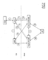
- FIG. 1 schematically shows a data packet based wireless mobile communications network.
- communication routes are denoted with numbers within a circle and will in the following text be labelled with the numbers only.
- the communication network comprises a core network CN and a radio area network RAN.
- the core network CN comprises a control plane node MME intercommunicating 1 with a user plane node UPE.
- the radio area network comprises a mobile user equipment UE intercommunicating 2 with an enhanced source radio base transceiver station source eNodeB.
- the user equipment may be a cellular telephone or a computer or the like.
- Payload data between the UE and the core network CN in the form of uplink UL data and downlink DL data is routed via a tunnel T1 between the user plane node UPE and the source eNodeB.
- Uplink relates to a payload data flow in the direction from the UE to the UPE and downlink relates to a payload data flow in the direction from the UPE to the UE.
- the tunnel T1 allows for both uplink and downlink communication.
- the UE is positioned within a cell (not shown) controlled by the source eNodeB and the communication is routed via the tunnel T1.
- the tunnel T1 needs to be switched from the source eNodeB to the target eNodeB. This is performed by a so called handover procedure, where the UPE moves the tunnel in the user plane. Before the tunnel T1 is switched, the UPE need information that the tunnel T1 shall be shifted.
- the mechanism of handing over radio control and radio management of the UE between different eNodeBs is handled by inter eNodeB communication 3.
- the communication signals 4a, 4b between the source and target eNodeBs respectively and the core network control plane node MME handles mobility management aspects for the UE.
- the communication signals 5a, 5b between source and target eNodeBs respectively and the core network CN user plane node UPE is used for handling the setup of a temporary tunnel T2 according to below..
- the handover comprises the step of establishing a temporary tunnel T2 (dotted line in figure 1 ) between the user plane node UPE and a target eNodeB when information has been received at the target eNodeB that a handover is about to take place.
- a temporary tunnel T2 (dotted line in figure 1 ) between the user plane node UPE and a target eNodeB when information has been received at the target eNodeB that a handover is about to take place.
- Such information can be supplied to the target eNodeB by the source eNodeB or directly by the UE, dependent on, for example, the resources allocated to the different eNodeBs and the UE.
- the handover is initiated by the target eNodeB transmitting an unreliable uplink data signal 5b a to the UPE comprising information that a handover is about to take place and that the downlink tunnel endpoint of tunnel T1 shall be moved from the source eNOdeB to the target eNodeB.
- the communication signals 5a between the UPE and the source eNodeB comprises both uplink and downlink traffic because of the already existing tunnel T1.
- the temporary tunnel allows for uplink 5b and downlink transmission as soon as the UPE has received and logged the unreliable uplink signal information comprising the endpoint information regarding the target eNodeB..
- the unreliable uplink signal comprises address information regarding the source eNOdeB and the target eNodeB so that the UPE can identify the source eNode and the target eNodeB.
- the unreliable uplink data information to the UPE may be in the form of a GTP-U message or information being embedded in an uplink GTP-U data packet head.
- the unreliable uplink data information to the UPE may comprise reference material regarding existing Tunnel Endpoint IDentifier, TEID, referring to the source eNodeB and information that this TEID shall not be used but that a new TEID identifying the target eNodeB shall be used instead. This information means that the temporary tunnel shall be permanent or, in case the temporary tunnel has failed, that a new tunnel shall be established.
- the UPE When the UPE receives the uplink signal 5b, it keeps the existing tunnel T1 open and establishes the temporary tunnel T2 by use of the endpoint information regarding the target eNOdeB comprised in the unreliable uplink data transmission.
- the target eNodeB transmits a reliable control signal 4b to the control plane node, MME, which in turn forwards 1 the reliable control signal to the user plane node, UPE.
- the reliable signal comprises information that the UPE shall either establish a tunnel between the UPE and the target eNodeB if no temporary tunnel has been established, or to permanent the temporary tunnel if it has been established.
- the reliable control signal is advantageously a GTP-C signal in a stream control transmission protocol or a SCTP, based two way stream communications system.
- the unreliable uplink data information/signal 5b to the user plane node, UPE, is transmitted before or simultaneously with the reliable control signal 4b to the control plane node, MME.
- the combination of the two gives a fast setup of the tunnel T2, which setup is faster than awaiting a setup of the tunnel T2 by the controlled signal via the MME only.
- the inventive method gives a fast and efficient handover by allowing for the setup of the tunnel T2 and at the same time a secure handover due to the existence of the control signal 4b.
- the fast path switching in the user plane provides a simple yet effective handover by not involving using acknowledgement signalling, while the authenticity and reliability of the procedure instead is guaranteed by the MME.
- the user plane node UPE comprises a timer (not shown) starting when the user plane node UPE has received the unreliable uplink data information from the target eNodeB.
- the user plane node UPE uses the timer starting time for calculating a time out period under which the reliable control signal 1 should be received by the user plane node UPE. If the reliable control signal is not received within the time period the temporary tunnel is withdrawn and the already existing tunnel between the user node plane UPE and the source eNOdeB is re-established.
- One advantage of the invention is that the tunnel T1 between the user plane node UPE and the source eNodeB is open for uplink and downlink data packet transmissions until the user plane node releases the tunnel, so that the user plane node UPE can re-route the user equipment UE transmission path to the already existing tunnel T1 should the temporary tunnel T2 be faulty or if a radio access parameter with the user equipment UE is transmitted to the user plane node UPE giving information that a switch from target eNodeB to source eNodeB is unsuitable.
- the user plane node UPE communicates 6 with other units, via a SAE GW, within the core network.
- the other units may be a computer server or another node transmitting and receiving information in another wireless network.
- Figure 2 schematically shows a sequence diagram for the handover according to the invention.
- the signalling delay from the interaction with MME/UPE may cause a problem when the time of the delay is comparable in size with the time of UE presence in a cell handled by source eNodeB until the UE moves to a cell handled by target eNodeB.
- the discussed timing problem is solved with the present invention by combining fast in-band-path-switching in the user plane in combination with an authenticated and reliable signalling in the control plane.
- the interface between the source eNodeB and the target eNodeB is by 3GPP named X2 and the interface between eNodeB and the combination of MME and UPE is named S1.
- the interface between eNodeB and MME is by this text named S1_C, and the interface between eNodeB and UPE is named S1_U.
- S1_C is intended for control signaling and the S1_U is intended for user payload transport.
- the selected transport communication protocol at the S1_C interface is Stream Control Transmission Protocol (hereinafter called SCTP), while the GPRS Tunneling Protocol-U (hereinafter called GTP-U) over the User Datagram Protocol (hereinafter called UDP) is selected for S1_U.
- SCTP Stream Control Transmission Protocol
- GTP-U GPRS Tunneling Protocol-U
- UDP User Datagram Protocol
- the payload related to a specific UE is differentiated from payload from other UEs by the GTP-U Tunnel Endpoint Identifier (hereinafter called TEID), one in uplink direction and one in downlink direction.
- TEID GTP-U Tunnel Endpoint Identifier
- the control signaling related to information exchange between the functional entity UPE and the functional entity MME is expected to be handled by one pair of SCTP streams in the S11 interface.
- the application layer protocol between the eNodeB and MME is expected to an evolution of the RANAP protocol (3GPP TS 25.413), here named eRANAP.
- the control signaling related to a specific UE is differentiated from signaling related to other UEs by an application layer identifier, eRANAP_UE_ID, as part of an application protocol unit carried in the SCTP association or the Payload Protocol Identifier PPI field of SCTP.
- an application layer identifier eRANAP_UE_ID
- the invention applies a combination of a fast unreliable hand over and an authorized and authenticated hand over of the UE between the source and the target eNodeBs.
- the fast unreliable hand over provides characteristics that meet the need of uninterrupted communication.
- the immediately following authorized and authenticated hand over adds the characteristics required by service provisioning as well as a security measure.
- the UE is in state LTE_ACTIVE and handled by eNodeB_1, MME_1 and UPE_1.
- the UE is moving into coverage of eNodeB_2.
- Figure 3 schematically shows a more detailed sequence diagram for the handover according to the invention.
- Figure 3 shows the following steps:
- Figure 4 schematically shows a sequence diagram for the RAN during the handover according to the invention.
- the sequence comprises the following steps:
- the present invention allows uplink data from both source eNodeB and target eNodeB during the handover session until the temporary tunnel has been become permanent. This is possible since the uplink data being sent from both the source and target eNodeB comprise GTP-U heads comprising re-routing information that makes the UPE accept the uplink data packets.
- the switching information
- the re-routing information in the GTP-U is used for giving information on whether the target and/or source eNodeB can handle downlink data packet, i.e. if the eNodeB in question has a functioning radio transport for downlink to the UE.
- Another advantage is that the uplink and downlink handling in the respective eNOdeB does not need to be synchronised in time.
- the invention allows for both a fast and reliable handover of UE between eNodeBs.
- the inventive method lowers the impact of denial-of-service attacks at the S1_U interface in case its protocol stack is implemented without integrity protection at the PDCP layer.
Landscapes
- Engineering & Computer Science (AREA)
- Computer Networks & Wireless Communication (AREA)
- Signal Processing (AREA)
- Mobile Radio Communication Systems (AREA)
Claims (11)
- Procédé de transfert intercellulaire pour un réseau de communication mobile sans fil à base de paquets de données, le réseau comprenant un réseau fédérateur (CN) et un réseau radio (RAN), le réseau fédérateur (CN) comprenant un noeud de plan de commande (MME) en intercommunication avec un noeud de plan utilisateur (UPE), le réseau radio comprenant un équipement utilisateur mobile (UE) en intercommunication avec une station radio d'émission-réception de base source, eNodeB, (station « eNodeB » source), dans lequel des données de charge utile entre l'équipement utilisateur (UE) et le réseau fédérateur (CN) sous la forme de données en liaison montante (UL) et de données en liaison descendante (DL) sont acheminées par le biais d'un tunnel entre le noeud de plan utilisateur (EPU) et la station « eNodeB » source (station « eNodeB » source) ;
caractérisé en ce que :le transfert intercellulaire comprend l'étape consistant à établir un tunnel temporaire entre le noeud de plan utilisateur (UPE) et une station « eNodeB » cible (station « eNodeB » cible), le transfert intercellulaire étant initié par la station « eNodeB » cible (station « eNodeB » cible) en transmettant un signal de données en liaison montante non fiable au noeud de plan utilisateur (UPE) comprenant des informations indiquant que le transfert intercellulaire est sur le point d'avoir lieu et que le tunnel doit être déplacé de la station « eNodeB » source (station « eNodeB » source) à la station « eNodeB » cible (station « eNodeB » cible). - Procédé de transfert intercellulaire selon la revendication 1, dans lequel le noeud de plan utilisateur (UPE) établit le tunnel temporaire lors de la réception d'informations en provenance de la station « eNodeB » cible (station « eNodeB » cible) comprenant l'adresse IP de plan utilisateur et l'identifiant de point d'extrémité de tunnel (TEID) de la station « eNodeB » cible en recevant des données en liaison montante au niveau de la station « eNodeB » cible (station « eNodeB » cible), ce qui permet par conséquent la transmission de paquets de données de charge utile en liaison descendante du noeud de plan utilisateur (UPE) à l'équipement utilisateur (UE) via le tunnel temporaire et la station « eNodeB » cible (eNodeB).
- Procédé de transfert intercellulaire selon l'une quelconque des revendications précédentes, dans lequel les informations de données en liaison montante non fiables transmises au noeud de plan utilisateur (UPE) représentent un message GTP-U ou des informations intégrées dans un en-tête de paquets de données GTP-U en liaison montante.
- Procédé de transfert intercellulaire selon l'une quelconque des revendications précédentes, dans lequel les informations de données en liaison montante non fiables transmises au noeud de plan utilisateur (UPE) comportent un support de référence concernant un identifiant TEID existant renvoyant à la station « eNodeB » source (station « eNodeB » source) et des informations indiquant que cet identifiant TEID ne doit pas être utilisé, mais qu'un nouvel identifiant TEID, identifiant la station « eNodeB » cible, doit être utilisé à la place.
- Procédé selon l'une quelconque des revendications précédentes, dans lequel la station « eNodeB » cible (station « eNodeB » cible) transmet un signal de commande fiable au noeud de plan de commande (MME), lequel achemine à son tour le signal de commande fiable au noeud de plan utilisateur (UPE), dans lequel le signal fiable comporte des informations indiquant que le noeud de plan utilisateur (UPE) doit établir un tunnel entre le noeud de plan utilisateur (UPE) et la station « eNodeB » cible (station « eNodeB » cible), lorsqu'aucun tunnel temporaire n'a été établi ou que le tunnel temporaire doit devenir permanent, lorsqu'il a été établi.
- Procédé de transfert intercellulaire selon la revendication 5, dans lequel le noeud de plan utilisateur (UPE) libère le tunnel entre le noeud de plan utilisateur (UPE) et la station « eNodeB » source (station « eNodeB » source), lorsque le tunnel entre le noeud de plan utilisateur (UPE) et la station « eNodeB » cible a été établi.
- Procédé de transfert intercellulaire selon la revendication 5 ou 6, dans lequel le tunnel entre le noeud de plan utilisateur (UPE) et la station « eNodeB » source (station « eNodeB » source) est ouvert pour des transmissions de paquets de données en liaison montante et en liaison descendante jusqu'à ce que le noeud de plan utilisateur (UPE) libère le tunnel, de sorte que le noeud de plan utilisateur (UPE) peut réacheminer le chemin de transmission d'équipement utilisateur (UE) vers le tunnel, lorsque le tunnel temporaire est défectueux ou lorsqu'un paramètre d'accès radio avec l'équipement utilisateur (UE) est transmis au noeud de plan utilisateur (UPE), donnant des informations indiquant qu'une commutation de la station « eNodeB » cible (station « eNodeB » cible) à la station « eNodeB » source (station « eNodeB » source) est inappropriée.
- Procédé de transfert intercellulaire selon l'une quelconque des revendications 5 à 7, dans lequel le noeud de plan utilisateur (UPE) comprend un temporisateur initié lorsque le noeud de plan utilisateur (UPE) a reçu les informations de données en liaison montante non fiables en provenance de la station « eNodeB » cible (station « eNodeB » cible), dans lequel le noeud de plan utilisateur (UPE) utilise l'instant de démarrage du temporisateur pour calculer une période de temporisation au-dessous de laquelle le signal de commande fiable doit être reçu par le noeud de plan utilisateur (UPE), et si le signal de commande fiable n'est pas reçu dans ladite période de temps, le tunnel temporaire est retiré et le tunnel existant entre le noeud de plan utilisateur (UPE) et la station « eNodeB » source (station « eNodeB » source) est conservé.
- Procédé de transfert intercellulaire selon l'une quelconque des revendications 5 à 8, dans lequel le signal de commande fiable est soit un signal GTP-C soit un signal de protocole d'application dans des communications de flux bidirectionnelles à base de protocoles de transmission de commande de flux (SCTP).
- Procédé de transfert intercellulaire selon l'une quelconque des revendications 5 à 9, dans lequel les informations de données en liaison montante non fiables vers le noeud de plan utilisateur (UPE) sont transmises avant ou simultanément au signal de commande fiable envoyé au noeud de plan de commande (MME).
- Système comprenant un noeud de plan de commande (MME) et un noeud de plan utilisateur (UPE) dans un réseau fédérateur (CN) en interaction avec une station « eNodeB » source (station « eNodeB » source) et une station « eNodeB » cible (station « eNodeB » cible), dans lequel le système est agencé de manière à mettre en oeuvre les étapes selon l'une quelconque des revendications 1 à 10.
Applications Claiming Priority (1)
| Application Number | Priority Date | Filing Date | Title |
|---|---|---|---|
| PCT/SE2007/050072 WO2008097147A1 (fr) | 2007-02-06 | 2007-02-06 | Procédé et système s'appliquant à un transfert cellulaire interne e-utran |
Publications (3)
| Publication Number | Publication Date |
|---|---|
| EP2135471A1 EP2135471A1 (fr) | 2009-12-23 |
| EP2135471A4 EP2135471A4 (fr) | 2010-01-27 |
| EP2135471B1 true EP2135471B1 (fr) | 2011-08-31 |
Family
ID=39681939
Family Applications (1)
| Application Number | Title | Priority Date | Filing Date |
|---|---|---|---|
| EP07709465A Not-in-force EP2135471B1 (fr) | 2007-02-06 | 2007-02-06 | Procédé et système s'appliquant à un transfert cellulaire interne e-utran |
Country Status (5)
| Country | Link |
|---|---|
| US (1) | US8259677B2 (fr) |
| EP (1) | EP2135471B1 (fr) |
| JP (1) | JP4834162B2 (fr) |
| AT (1) | ATE523051T1 (fr) |
| WO (2) | WO2008097147A1 (fr) |
Cited By (2)
| Publication number | Priority date | Publication date | Assignee | Title |
|---|---|---|---|---|
| US9680695B2 (en) | 2014-10-24 | 2017-06-13 | At&T Intellectual Property I, L.P. | Facilitating mobility dimensioning via dynamic configuration of a switch |
| US9924416B2 (en) | 2013-08-01 | 2018-03-20 | Nokia Technologies Oy | Methods, apparatuses and computer program products for fast handover |
Families Citing this family (25)
| Publication number | Priority date | Publication date | Assignee | Title |
|---|---|---|---|---|
| EP2667661B1 (fr) | 2006-06-20 | 2017-05-03 | InterDigital Technology Corporation | Faciliter le transfert intercellulaire dans un système LTE |
| GB2449629A (en) | 2007-05-01 | 2008-12-03 | Nec Corp | Buffering numbered unsegmented PDCP SDUs in 3GPP system to assist efficient hard handover |
| GB2454647B (en) * | 2007-10-05 | 2010-02-17 | Samsung Electronics Co Ltd | Mobile communications method and apparatus |
| CN101472314B (zh) | 2007-11-02 | 2010-05-12 | 华为技术有限公司 | 一种数据处理方法和设备 |
| US20090290554A1 (en) * | 2008-05-13 | 2009-11-26 | Nokia Siemens Networks Oy | System, method and computer accessible medium for determining action time in a communication network |
| US9161378B2 (en) * | 2008-06-23 | 2015-10-13 | Qualcomm Incorporated | Concentrator for multiplexing access point to wireless network connections |
| US8451800B2 (en) * | 2009-08-06 | 2013-05-28 | Movik Networks, Inc. | Session handover in mobile-network content-delivery devices |
| EP2164289A1 (fr) * | 2008-09-12 | 2010-03-17 | Nokia Siemens Networks OY | Procédé de changement de chaînes de radio, réseau composé et routeur d'accès |
| US8902805B2 (en) * | 2008-10-24 | 2014-12-02 | Qualcomm Incorporated | Cell relay packet routing |
| WO2010069400A1 (fr) * | 2008-12-19 | 2010-06-24 | Telefonaktiebolaget Lm Ericsson (Publ) | Procédé et entité pour transmettre des unités de données |
| CN101448268B (zh) * | 2008-12-26 | 2012-01-25 | 华为技术有限公司 | 邻区配置方法及装置和家庭基站配置方法及装置 |
| KR101521886B1 (ko) * | 2009-01-23 | 2015-05-28 | 삼성전자주식회사 | 이동통신 시스템에서 지티피 처리를 위한 장치 및 방법 |
| WO2010085913A1 (fr) * | 2009-02-02 | 2010-08-05 | 华为技术有限公司 | Procédé, dispositif et système de transfert intercellulaire à plusieurs porteuses |
| CN101873654B (zh) * | 2009-04-22 | 2013-09-11 | 电信科学技术研究院 | 一种测量上下文的处理方法及设备 |
| CN102170667B (zh) * | 2010-02-25 | 2013-02-27 | 中兴通讯股份有限公司 | 一种实现基站间切换的方法、系统及基站装置 |
| EP2578043B1 (fr) * | 2010-05-26 | 2016-09-07 | Telefonaktiebolaget LM Ericsson (publ) | Etats de connexion pour une entité d'utilisateur dans une passerelle de desserte d'un système de réseau fédérateur à paquets évolués |
| CN102300207A (zh) * | 2010-06-24 | 2011-12-28 | 中兴通讯股份有限公司 | 一种基站自配置过程获取基本配置参数的自愈方法及基站 |
| WO2012031626A2 (fr) * | 2010-09-08 | 2012-03-15 | Nokia Siemens Networks Oy | Réglage des paramètres d'accès radio |
| KR101712801B1 (ko) * | 2010-12-06 | 2017-03-07 | 삼성전자주식회사 | 휴대용 단말기의 안테나 장치 및 그 운용 방법 |
| CA2824011C (fr) | 2011-01-06 | 2019-04-30 | Nec Corporation | Systeme de determination de regles, procede de determination de regles, et support lisible par ordinateur non temporaire |
| US9451503B2 (en) * | 2011-08-31 | 2016-09-20 | Panasonic Intellectual Property Management Co., Ltd. | Mobile terminal and method for controlling rate change |
| US20130272219A1 (en) * | 2012-03-13 | 2013-10-17 | Qualcomm Incorporated | Methods and apparatus for backhaul sharing by femtocells |
| CN103533589B (zh) * | 2012-07-04 | 2018-03-13 | 华为技术有限公司 | 一种网络切换方法、系统及网络侧设备 |
| US10104705B2 (en) * | 2014-11-05 | 2018-10-16 | Intel IP Corporation | Apparatus, system and method of communicating between a cellular manager and a user equipment (UE) via a WLAN access device |
| CN110035422B (zh) * | 2018-01-12 | 2021-01-22 | 大唐移动通信设备有限公司 | 基于临时处理隧道表的上行数据处理方法、mme和sgw |
Family Cites Families (2)
| Publication number | Priority date | Publication date | Assignee | Title |
|---|---|---|---|---|
| CN101204103B (zh) * | 2005-06-21 | 2011-07-06 | 摩托罗拉移动公司 | 减少无线连通性改变期间的延迟的方法和设备 |
| WO2007103369A2 (fr) * | 2006-03-07 | 2007-09-13 | Interdigital Technology Corporation | Procédé et appareil pour la prise en charge du transfert intercellulaire dans un système de communication sans fil lte gtp |
-
2007
- 2007-02-06 JP JP2009549031A patent/JP4834162B2/ja not_active Expired - Fee Related
- 2007-02-06 WO PCT/SE2007/050072 patent/WO2008097147A1/fr active Application Filing
- 2007-02-06 US US12/525,706 patent/US8259677B2/en active Active
- 2007-02-06 EP EP07709465A patent/EP2135471B1/fr not_active Not-in-force
- 2007-02-06 AT AT07709465T patent/ATE523051T1/de not_active IP Right Cessation
-
2008
- 2008-02-05 WO PCT/EP2008/051413 patent/WO2008095936A2/fr active Application Filing
Cited By (2)
| Publication number | Priority date | Publication date | Assignee | Title |
|---|---|---|---|---|
| US9924416B2 (en) | 2013-08-01 | 2018-03-20 | Nokia Technologies Oy | Methods, apparatuses and computer program products for fast handover |
| US9680695B2 (en) | 2014-10-24 | 2017-06-13 | At&T Intellectual Property I, L.P. | Facilitating mobility dimensioning via dynamic configuration of a switch |
Also Published As
| Publication number | Publication date |
|---|---|
| US20100232391A1 (en) | 2010-09-16 |
| EP2135471A4 (fr) | 2010-01-27 |
| JP2010518739A (ja) | 2010-05-27 |
| ATE523051T1 (de) | 2011-09-15 |
| US8259677B2 (en) | 2012-09-04 |
| WO2008097147A1 (fr) | 2008-08-14 |
| WO2008095936A2 (fr) | 2008-08-14 |
| WO2008095936A3 (fr) | 2009-02-12 |
| WO2008095936A9 (fr) | 2009-07-09 |
| JP4834162B2 (ja) | 2011-12-14 |
| EP2135471A1 (fr) | 2009-12-23 |
Similar Documents
| Publication | Publication Date | Title |
|---|---|---|
| EP2135471B1 (fr) | Procédé et système s'appliquant à un transfert cellulaire interne e-utran | |
| US9426700B2 (en) | Method and apparatus for performing handover procedure in wireless communication system including mobile relay node | |
| WO2020087368A1 (fr) | Appareil et mécanisme de ré-ordonnancement à double protocole pour réduire une interruption de mobilité dans un réseau sans fil | |
| US9872208B2 (en) | Data forwarding method and device | |
| US10206148B2 (en) | Preserving core network interfaces after selective handovers in a wireless network | |
| US10560882B2 (en) | Method and apparatus for multi-rat transmission | |
| US9161281B2 (en) | Method and apparatus for multi-rat transmission | |
| US8320827B2 (en) | Method and apparatus for performing handover with a relay node | |
| KR101550464B1 (ko) | 이동통신 시스템 및 그의 핸드오버 절차 처리방법 | |
| KR101344400B1 (ko) | 기지국간 핸드오버시의 패킷 포워딩 방법 | |
| EP2574107B1 (fr) | Transfert à commutation par paquets dans un système de communication mobile, pendant lequel une station mobile reçoit des paquets d'un noeud d'origine et d'un noeud de destination | |
| CN104509161B (zh) | 切换处理方法及基站 | |
| CN112088544A (zh) | 通过施主基站切换来维持通信和信令接口 | |
| US9749910B2 (en) | Method and apparatus for transmitting user equipment group information in wireless communication system | |
| EP3177071A1 (fr) | Procédé de commutation de station de base par un équipement d'utilisateur, station de base et équipement d'utilisateur | |
| US20150131535A1 (en) | Node and Method for Establishing Auxiliary Bearers | |
| US20120243461A1 (en) | Relay handover control | |
| CN113873596A (zh) | 双连接架构下支持业务本地分流的方法及设备 | |
| US20180041932A1 (en) | Base station and communication control method | |
| CN102883380A (zh) | Lte系统中支持用户设备移动性的方法 |
Legal Events
| Date | Code | Title | Description |
|---|---|---|---|
| PUAI | Public reference made under article 153(3) epc to a published international application that has entered the european phase |
Free format text: ORIGINAL CODE: 0009012 |
|
| 17P | Request for examination filed |
Effective date: 20090828 |
|
| AK | Designated contracting states |
Kind code of ref document: A1 Designated state(s): AT BE BG CH CY CZ DE DK EE ES FI FR GB GR HU IE IS IT LI LT LU LV MC NL PL PT RO SE SI SK TR |
|
| RIC1 | Information provided on ipc code assigned before grant |
Ipc: H04W 4/00 20090101AFI20091120BHEP |
|
| A4 | Supplementary search report drawn up and despatched |
Effective date: 20100104 |
|
| RIC1 | Information provided on ipc code assigned before grant |
Ipc: H04W 36/08 20090101AFI20091223BHEP |
|
| 17Q | First examination report despatched |
Effective date: 20100413 |
|
| DAX | Request for extension of the european patent (deleted) | ||
| GRAP | Despatch of communication of intention to grant a patent |
Free format text: ORIGINAL CODE: EPIDOSNIGR1 |
|
| GRAS | Grant fee paid |
Free format text: ORIGINAL CODE: EPIDOSNIGR3 |
|
| GRAA | (expected) grant |
Free format text: ORIGINAL CODE: 0009210 |
|
| AK | Designated contracting states |
Kind code of ref document: B1 Designated state(s): AT BE BG CH CY CZ DE DK EE ES FI FR GB GR HU IE IS IT LI LT LU LV MC NL PL PT RO SE SI SK TR |
|
| REG | Reference to a national code |
Ref country code: GB Ref legal event code: FG4D Ref country code: CH Ref legal event code: EP |
|
| REG | Reference to a national code |
Ref country code: IE Ref legal event code: FG4D |
|
| REG | Reference to a national code |
Ref country code: DE Ref legal event code: R096 Ref document number: 602007016757 Country of ref document: DE Effective date: 20111103 |
|
| REG | Reference to a national code |
Ref country code: NL Ref legal event code: VDEP Effective date: 20110831 |
|
| LTIE | Lt: invalidation of european patent or patent extension |
Effective date: 20110831 |
|
| PG25 | Lapsed in a contracting state [announced via postgrant information from national office to epo] |
Ref country code: SE Free format text: LAPSE BECAUSE OF FAILURE TO SUBMIT A TRANSLATION OF THE DESCRIPTION OR TO PAY THE FEE WITHIN THE PRESCRIBED TIME-LIMIT Effective date: 20110831 Ref country code: LT Free format text: LAPSE BECAUSE OF FAILURE TO SUBMIT A TRANSLATION OF THE DESCRIPTION OR TO PAY THE FEE WITHIN THE PRESCRIBED TIME-LIMIT Effective date: 20110831 Ref country code: NL Free format text: LAPSE BECAUSE OF FAILURE TO SUBMIT A TRANSLATION OF THE DESCRIPTION OR TO PAY THE FEE WITHIN THE PRESCRIBED TIME-LIMIT Effective date: 20110831 Ref country code: FI Free format text: LAPSE BECAUSE OF FAILURE TO SUBMIT A TRANSLATION OF THE DESCRIPTION OR TO PAY THE FEE WITHIN THE PRESCRIBED TIME-LIMIT Effective date: 20110831 Ref country code: IS Free format text: LAPSE BECAUSE OF FAILURE TO SUBMIT A TRANSLATION OF THE DESCRIPTION OR TO PAY THE FEE WITHIN THE PRESCRIBED TIME-LIMIT Effective date: 20111231 |
|
| REG | Reference to a national code |
Ref country code: AT Ref legal event code: MK05 Ref document number: 523051 Country of ref document: AT Kind code of ref document: T Effective date: 20110831 |
|
| PG25 | Lapsed in a contracting state [announced via postgrant information from national office to epo] |
Ref country code: AT Free format text: LAPSE BECAUSE OF FAILURE TO SUBMIT A TRANSLATION OF THE DESCRIPTION OR TO PAY THE FEE WITHIN THE PRESCRIBED TIME-LIMIT Effective date: 20110831 Ref country code: SI Free format text: LAPSE BECAUSE OF FAILURE TO SUBMIT A TRANSLATION OF THE DESCRIPTION OR TO PAY THE FEE WITHIN THE PRESCRIBED TIME-LIMIT Effective date: 20110831 Ref country code: LV Free format text: LAPSE BECAUSE OF FAILURE TO SUBMIT A TRANSLATION OF THE DESCRIPTION OR TO PAY THE FEE WITHIN THE PRESCRIBED TIME-LIMIT Effective date: 20110831 Ref country code: GR Free format text: LAPSE BECAUSE OF FAILURE TO SUBMIT A TRANSLATION OF THE DESCRIPTION OR TO PAY THE FEE WITHIN THE PRESCRIBED TIME-LIMIT Effective date: 20111201 Ref country code: CY Free format text: LAPSE BECAUSE OF FAILURE TO SUBMIT A TRANSLATION OF THE DESCRIPTION OR TO PAY THE FEE WITHIN THE PRESCRIBED TIME-LIMIT Effective date: 20110831 |
|
| PG25 | Lapsed in a contracting state [announced via postgrant information from national office to epo] |
Ref country code: BE Free format text: LAPSE BECAUSE OF FAILURE TO SUBMIT A TRANSLATION OF THE DESCRIPTION OR TO PAY THE FEE WITHIN THE PRESCRIBED TIME-LIMIT Effective date: 20110831 |
|
| PG25 | Lapsed in a contracting state [announced via postgrant information from national office to epo] |
Ref country code: CZ Free format text: LAPSE BECAUSE OF FAILURE TO SUBMIT A TRANSLATION OF THE DESCRIPTION OR TO PAY THE FEE WITHIN THE PRESCRIBED TIME-LIMIT Effective date: 20110831 Ref country code: SK Free format text: LAPSE BECAUSE OF FAILURE TO SUBMIT A TRANSLATION OF THE DESCRIPTION OR TO PAY THE FEE WITHIN THE PRESCRIBED TIME-LIMIT Effective date: 20110831 |
|
| PG25 | Lapsed in a contracting state [announced via postgrant information from national office to epo] |
Ref country code: IT Free format text: LAPSE BECAUSE OF FAILURE TO SUBMIT A TRANSLATION OF THE DESCRIPTION OR TO PAY THE FEE WITHIN THE PRESCRIBED TIME-LIMIT Effective date: 20110831 Ref country code: PL Free format text: LAPSE BECAUSE OF FAILURE TO SUBMIT A TRANSLATION OF THE DESCRIPTION OR TO PAY THE FEE WITHIN THE PRESCRIBED TIME-LIMIT Effective date: 20110831 Ref country code: RO Free format text: LAPSE BECAUSE OF FAILURE TO SUBMIT A TRANSLATION OF THE DESCRIPTION OR TO PAY THE FEE WITHIN THE PRESCRIBED TIME-LIMIT Effective date: 20110831 Ref country code: EE Free format text: LAPSE BECAUSE OF FAILURE TO SUBMIT A TRANSLATION OF THE DESCRIPTION OR TO PAY THE FEE WITHIN THE PRESCRIBED TIME-LIMIT Effective date: 20110831 Ref country code: PT Free format text: LAPSE BECAUSE OF FAILURE TO SUBMIT A TRANSLATION OF THE DESCRIPTION OR TO PAY THE FEE WITHIN THE PRESCRIBED TIME-LIMIT Effective date: 20120102 |
|
| PG25 | Lapsed in a contracting state [announced via postgrant information from national office to epo] |
Ref country code: DK Free format text: LAPSE BECAUSE OF FAILURE TO SUBMIT A TRANSLATION OF THE DESCRIPTION OR TO PAY THE FEE WITHIN THE PRESCRIBED TIME-LIMIT Effective date: 20110831 |
|
| PLBE | No opposition filed within time limit |
Free format text: ORIGINAL CODE: 0009261 |
|
| STAA | Information on the status of an ep patent application or granted ep patent |
Free format text: STATUS: NO OPPOSITION FILED WITHIN TIME LIMIT |
|
| 26N | No opposition filed |
Effective date: 20120601 |
|
| REG | Reference to a national code |
Ref country code: DE Ref legal event code: R097 Ref document number: 602007016757 Country of ref document: DE Effective date: 20120601 |
|
| PG25 | Lapsed in a contracting state [announced via postgrant information from national office to epo] |
Ref country code: MC Free format text: LAPSE BECAUSE OF NON-PAYMENT OF DUE FEES Effective date: 20120229 |
|
| REG | Reference to a national code |
Ref country code: CH Ref legal event code: PL |
|
| PG25 | Lapsed in a contracting state [announced via postgrant information from national office to epo] |
Ref country code: LI Free format text: LAPSE BECAUSE OF NON-PAYMENT OF DUE FEES Effective date: 20120229 Ref country code: CH Free format text: LAPSE BECAUSE OF NON-PAYMENT OF DUE FEES Effective date: 20120229 |
|
| REG | Reference to a national code |
Ref country code: IE Ref legal event code: MM4A |
|
| PG25 | Lapsed in a contracting state [announced via postgrant information from national office to epo] |
Ref country code: IE Free format text: LAPSE BECAUSE OF NON-PAYMENT OF DUE FEES Effective date: 20120206 |
|
| PG25 | Lapsed in a contracting state [announced via postgrant information from national office to epo] |
Ref country code: ES Free format text: LAPSE BECAUSE OF FAILURE TO SUBMIT A TRANSLATION OF THE DESCRIPTION OR TO PAY THE FEE WITHIN THE PRESCRIBED TIME-LIMIT Effective date: 20111211 |
|
| PG25 | Lapsed in a contracting state [announced via postgrant information from national office to epo] |
Ref country code: BG Free format text: LAPSE BECAUSE OF FAILURE TO SUBMIT A TRANSLATION OF THE DESCRIPTION OR TO PAY THE FEE WITHIN THE PRESCRIBED TIME-LIMIT Effective date: 20111130 |
|
| PG25 | Lapsed in a contracting state [announced via postgrant information from national office to epo] |
Ref country code: TR Free format text: LAPSE BECAUSE OF FAILURE TO SUBMIT A TRANSLATION OF THE DESCRIPTION OR TO PAY THE FEE WITHIN THE PRESCRIBED TIME-LIMIT Effective date: 20110831 |
|
| PG25 | Lapsed in a contracting state [announced via postgrant information from national office to epo] |
Ref country code: LU Free format text: LAPSE BECAUSE OF NON-PAYMENT OF DUE FEES Effective date: 20120206 |
|
| PG25 | Lapsed in a contracting state [announced via postgrant information from national office to epo] |
Ref country code: HU Free format text: LAPSE BECAUSE OF FAILURE TO SUBMIT A TRANSLATION OF THE DESCRIPTION OR TO PAY THE FEE WITHIN THE PRESCRIBED TIME-LIMIT Effective date: 20070206 |
|
| REG | Reference to a national code |
Ref country code: FR Ref legal event code: PLFP Year of fee payment: 10 |
|
| REG | Reference to a national code |
Ref country code: FR Ref legal event code: PLFP Year of fee payment: 11 |
|
| REG | Reference to a national code |
Ref country code: FR Ref legal event code: PLFP Year of fee payment: 12 |
|
| PGFP | Annual fee paid to national office [announced via postgrant information from national office to epo] |
Ref country code: GB Payment date: 20200227 Year of fee payment: 14 Ref country code: DE Payment date: 20200227 Year of fee payment: 14 |
|
| PGFP | Annual fee paid to national office [announced via postgrant information from national office to epo] |
Ref country code: FR Payment date: 20200225 Year of fee payment: 14 |
|
| REG | Reference to a national code |
Ref country code: DE Ref legal event code: R119 Ref document number: 602007016757 Country of ref document: DE |
|
| GBPC | Gb: european patent ceased through non-payment of renewal fee |
Effective date: 20210206 |
|
| PG25 | Lapsed in a contracting state [announced via postgrant information from national office to epo] |
Ref country code: FR Free format text: LAPSE BECAUSE OF NON-PAYMENT OF DUE FEES Effective date: 20210228 Ref country code: GB Free format text: LAPSE BECAUSE OF NON-PAYMENT OF DUE FEES Effective date: 20210206 Ref country code: DE Free format text: LAPSE BECAUSE OF NON-PAYMENT OF DUE FEES Effective date: 20210901 |