EP2135172B1 - System und verfahren zum glätten abgetasteter digitalsignale - Google Patents
System und verfahren zum glätten abgetasteter digitalsignale Download PDFInfo
- Publication number
- EP2135172B1 EP2135172B1 EP08732443.0A EP08732443A EP2135172B1 EP 2135172 B1 EP2135172 B1 EP 2135172B1 EP 08732443 A EP08732443 A EP 08732443A EP 2135172 B1 EP2135172 B1 EP 2135172B1
- Authority
- EP
- European Patent Office
- Prior art keywords
- data
- data point
- value
- sampled
- point
- Prior art date
- Legal status (The legal status is an assumption and is not a legal conclusion. Google has not performed a legal analysis and makes no representation as to the accuracy of the status listed.)
- Not-in-force
Links
Images








Classifications
-
- A—HUMAN NECESSITIES
- A61—MEDICAL OR VETERINARY SCIENCE; HYGIENE
- A61N—ELECTROTHERAPY; MAGNETOTHERAPY; RADIATION THERAPY; ULTRASOUND THERAPY
- A61N1/00—Electrotherapy; Circuits therefor
- A61N1/18—Applying electric currents by contact electrodes
- A61N1/32—Applying electric currents by contact electrodes alternating or intermittent currents
- A61N1/36—Applying electric currents by contact electrodes alternating or intermittent currents for stimulation
- A61N1/362—Heart stimulators
- A61N1/37—Monitoring; Protecting
- A61N1/3702—Physiological parameters
-
- A—HUMAN NECESSITIES
- A61—MEDICAL OR VETERINARY SCIENCE; HYGIENE
- A61N—ELECTROTHERAPY; MAGNETOTHERAPY; RADIATION THERAPY; ULTRASOUND THERAPY
- A61N1/00—Electrotherapy; Circuits therefor
- A61N1/02—Details
- A61N1/025—Digital circuitry features of electrotherapy devices, e.g. memory, clocks, processors
-
- H—ELECTRICITY
- H03—ELECTRONIC CIRCUITRY
- H03M—CODING; DECODING; CODE CONVERSION IN GENERAL
- H03M7/00—Conversion of a code where information is represented by a given sequence or number of digits to a code where the same, similar or subset of information is represented by a different sequence or number of digits
- H03M7/30—Compression; Expansion; Suppression of unnecessary data, e.g. redundancy reduction
- H03M7/40—Conversion to or from variable length codes, e.g. Shannon-Fano code, Huffman code, Morse code
-
- A—HUMAN NECESSITIES
- A61—MEDICAL OR VETERINARY SCIENCE; HYGIENE
- A61B—DIAGNOSIS; SURGERY; IDENTIFICATION
- A61B5/00—Measuring for diagnostic purposes; Identification of persons
- A61B5/0002—Remote monitoring of patients using telemetry, e.g. transmission of vital signals via a communication network
- A61B5/0004—Remote monitoring of patients using telemetry, e.g. transmission of vital signals via a communication network characterised by the type of physiological signal transmitted
- A61B5/0006—ECG or EEG signals
-
- A—HUMAN NECESSITIES
- A61—MEDICAL OR VETERINARY SCIENCE; HYGIENE
- A61B—DIAGNOSIS; SURGERY; IDENTIFICATION
- A61B5/00—Measuring for diagnostic purposes; Identification of persons
- A61B5/0002—Remote monitoring of patients using telemetry, e.g. transmission of vital signals via a communication network
- A61B5/0031—Implanted circuitry
-
- A—HUMAN NECESSITIES
- A61—MEDICAL OR VETERINARY SCIENCE; HYGIENE
- A61B—DIAGNOSIS; SURGERY; IDENTIFICATION
- A61B5/00—Measuring for diagnostic purposes; Identification of persons
- A61B5/72—Signal processing specially adapted for physiological signals or for diagnostic purposes
- A61B5/7232—Signal processing specially adapted for physiological signals or for diagnostic purposes involving compression of the physiological signal, e.g. to extend the signal recording period
-
- A—HUMAN NECESSITIES
- A61—MEDICAL OR VETERINARY SCIENCE; HYGIENE
- A61B—DIAGNOSIS; SURGERY; IDENTIFICATION
- A61B5/00—Measuring for diagnostic purposes; Identification of persons
- A61B5/72—Signal processing specially adapted for physiological signals or for diagnostic purposes
- A61B5/7235—Details of waveform analysis
- A61B5/7239—Details of waveform analysis using differentiation including higher order derivatives
Definitions
- the present invention relates to data storage and processing and in particular data storage and processing with data obtained from an implantable medical device.
- IMDs implantable medical devices
- IPGs implantable pulse generators
- ICDs implantable cardiac defibrillators
- ILRs implantable loop recorders
- IMDs are commonly used in a wide variety of other applications.
- neurological devices may stimulate or gather information from the brain or portions of the nervous system.
- Devices may be provided to monitor glucose levels and dispense insulin. The use and applicability of IMDs is constantly expanding into additional anatomical and physiological fields.
- IMDs may be quite different in form, function, and operation there are certain characteristics that will apply generally.
- a device As the device is implanted within the patient (and generally not readily accessible), such a device should be reliable, self sustaining for an appropriate period of time, and when appropriate, have the ability to communicate with other implanted devices or devices external to the patient.
- Certain desirable characteristics will tend to compete against one another. For example, minimizing the size of a given device is generally preferred; however, this in turn limits the space available for internal components. Similarly, there is a preference to have as many features or functions as possible; but this taxes the already limited resources in terms of power consumption and internal components.
- Information or data is in some form a physical construct that behaves and can be manipulated according to certain laws, regardless of the particular storage medium or mechanism.
- information can be discussed in terms of scientific principles such as thermodynamics, quantum mechanics and the like.
- the concept of entropy from the second law of thermodynamics is useful in describing quantities of non-redundant data in a set.
- IMDs This is useful in that there is a continuing desire to develop and operate IMDs efficiently and effectively, while maximizing the benefit and usefulness of scarce resources.
- One area often considered is internal memory and information processing.
- resources e.g., memory
- the amount of information expected to be collected and stored increases.
- US 2003/0083581 shows an apparatus and method for dynamically selecting an ECG compression process based on ECG signal separation process and an signal analysis process.
- US 5 623 935 shows an apparatus and method for ECG data compression comprising calculation of the signals derivative and selection of an appropriate compression mode.
- US 2002/0193668 shows a method and system for compressing and storing ECG data in an implantable medical device with limited storage.
- FIG. 1 is a block diagram illustrating some, but certainly not all of the components of a typical implantable medical device (IMD) 100.
- IMD implantable medical device
- FIG. 1 is provided simply for illustrative and non-limiting purposes.
- the IMD 100 includes an appropriate housing 102 enclosing the various components.
- One or more microprocessors 120 are typically provided along with a power supply 122 which usually includes a battery and capacitors (for high voltage therapy).
- One or more memory modules 124 are provided in various forms that may include operating instructions and/or receive and store data collected by the IMD 100.
- the IMD 100 includes a transceiver 126 that permits two-way communication between the IMD 100 and an external (to the patient) device and/or another implanted device.
- a therapy module 128 is illustrated and generally includes the components and instructions to provide one or more therapies, if the IMD 100 is so equipped. Examples may include pacing, defibrillation, neural stimulation, drug delivery and so on.
- a signal processor 130 receives and processes data.
- An analog to digital converter (ADC) 132 receives a raw or processed analog signal and convert that signal into digital data.
- the IMD 100 may include on or more sense amplifiers 134 that receive data from one or more sensors 138, 140 and then output the amplified signal to other components within the IMD 100.
- a given sensor 138 may be coupled directly with the housing 102 or a remote sensor 140 may be coupled via a lead 142 or through wireless communication.
- the IMD 100 includes a data compression module 136 that compresses data before storing that data into memory 132. Also included is a smoothing / filter module 160.
- cardiac data for example, is collected by the IMD 100, it is referred to as an electrogram (EGM) as opposed to surface collected data in the form of an electrocardiogram (EKG or ECG).
- EGM electrogram
- EKG electrocardiogram
- the EGM data is stored in the memory 124 until it is telemetered out, the IMD 100 is extracted, or the memory capacity is exceeded and the data is overwritten.
- the IMD 100 includes a finite memory and has a limited power supply; thus, care is taken to minimize any unnecessary power consumption. Under these conditions, the data compression module 136 seeks to optimally compress the data in a lossless manner, when appropriate and in some cases permits a lossy data compression.
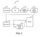
- FIG. 2 is a block diagram illustrating data compression module 136.
- An analog signal 200 such as a cardiac waveform, is obtained and converted into digitized data 210 by the ADC 206 (or ADC 32 of FIG. 1 ).
- the analog signal is sampled at some predetermined sampling frequency (e.g., 1 MHz) and the value of the waveform is recorded for each sampled point in time.
- the value will be a voltage on the order of milivolts.
- the resolution is defined between rails (upper and lower limits) by the total available increments (typically equal). For example, with 256 discrete increments the above example would be a sample frequency of 1 MHz with 8 bit resolution. 12 bit resolution would provide 4096 increments and so on.
- the sampled digital waveform data 210 passes through a linear predictive encoder 215 which acts to simplify the waveform for subsequent processing.
- a linear predictive encoder 215 acts to simplify the waveform for subsequent processing.
- the derivative of the sampled waveform is obtained. More specifically, the first data point and certain subsequent data points are left intact while the remaining sampled data points are converted into the difference between a given data point and the previous data point. Thus, the first data point remains the sampled value.
- the second data point becomes the difference between the second sampled value and the first sampled value.
- the third data point becomes the difference between the third sampled value and the second sampled value. To decode this data, the reverse process is performed. Again, the first data point is intact.
- the second data point is obtained by adding the difference stored in memory to the first data point and so on.
- the linear predictive encoder 215 encodes the data into a form that generates a probability distribution that is generally centered about a zero baseline and has approximately the same shape (despite general variations in original waveforms of the same type) for the highest probability data points. This allows for the subsequent partial application of Huffman encoding which maps certain potential increments or values to a "codeword.” By using relatively short codewords for the most frequently used increments (those having the highest probability of use) a first order of data compression is achieved. For example, a codeword representing an 8 bit value might only have 2 bits; thus a compression ratio of 4:1 is achieved. To provide a complete Huffman encoded alphabet for all potential values, some data points will map to significantly longer codewords.
- one codeword will have 256 bits. Therefore, to achieve an overall compression ratio that is positive, the probability that given data points are obtained is an element that should be known and controlled for; hence an understanding and calculation of entropy.
- the mapping of codewords to their values is stored in a lookup table in software, hardware or firmware and is available for both encoding and decoding.
- the lookup table could be contained within the linear predictive encoder 215 or stored within memory 124 and accessible by the linear predictive encoder 215.
- a single lookup table provides the simplest scheme; however, it should be appreciated, that multiple lookup tables may be provided and the appropriate table is selected based upon waveform type, point in time, or some other factor.
- the mapped codewords are equal to or shorter than the data they map to (e.g., 8 bits or less). Outside of this band, the codewords are longer than the data they represent (e.g., 9 bits or longer with our 8 bit example).
- each data point sampled will be 8 bits long; in order to achieve data compression, codewords having less than 8 bits must be used for at least some data points. If shorter codewords were always used then every data point would achieve compression; however, in order to provide codewords for all potential data points, some of these codewords become very long.
- the overall data scheme achieves compression, when properly mapped with probability. Further analyzing the derivative data, it is possible to determine which data points/codewords are equal to or less than the current bit rate (e.g., 8 bits or less).
- the data parsed by the linear predictive encoder 215 is subjected to a rule processor 220 that evaluates whether, at a high level, the current data point is inside or outside of this optimized band. If the data is within the optimized band, then the codewords are substituted for the data by the truncated entropy encoder 225 and stored in memory 230 (which may or may not be the same as memory 124 of FIG. 1 ). If the data is outside of the band then the codewords are not used; rather, the raw (e.g. 8 bit data) is stored directly in the memory 230. While no compression is achieved for these data points, there is no extra memory usage for what would have been a longer codeword. While achieving good results, actual implementation is somewhat more complex in that both the encoder and separately the decoder need to be able to distinguish between codewords and raw data.
- one mechanism employed by the rule processor 220 is to determine whether the previous data point should or should not have been encoded.
- the first data point that occurs as a waveform transitions e.g., out of the optimum band will be encoded even though according to the above logic it should not have been.
- the rule processor considers whether the previous data point should or should not have been encoded. If the determination is that the previous data point should have been encoded, then the current data point in encoded. Conversely, if the previous data point should not have been encoded, then the current data point is not encoded.
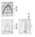
- FIGS. 3-7 illustrate various sampled waveforms, derivatives of those waveforms and probability distributions for the waveform and derivative waveforms.
- FIG. 3A is a sampled waveform of a cardiac EGM from a normal sinus rhythm.
- FIG. 3B is the derivative of the waveform of 3A, wherein the first data point remains unchanged but each subsequent data point becomes the difference between the current data point value and the previous data point value.
- the sample waveform data will have data points 1, 2, 3, 4, etc. (with each having some measured value for voltage and designated 8 bit value for that voltage).
- the derivative waveform will have data points 1, (2 - 1), (3 - 2), (4 - 3), etc.
- linear predictive encoding This is referred to herein as linear predictive encoding. That is, a model or an equation is established. For each data point the model will provide an expected or predicted value. The actual data point is compared with the predicted value and the difference or error is stored rather than the data point. If a predictive equation were perfect, then the error would be zero (0) for each data point. That is, given the value for the first data point, the model will accurately predict each subsequent data point precisely. As an example, if the waveform were a pure sine wave, its derivative is a cosine; thus, given a starting point or series of initial points each subsequent point is calculated with certainty.
- each data point is equal to the previous data point.
- the difference between the predicted value (i.e., the last data point) and the sampled value is the error for the model and this value is stored.
- various algebraic models may be provided that are more complex than the example above.
- these models may be non-linear and may consider any number of previous data points in predicting the current value. The more accurate the predictive model, the smaller the error values and the more effective the encoding.
- FIG. 3C is a probability distribution of the values of the sampled waveform in FIG. 3A and illustrates why the predictive encoding is useful.
- the X axis represents probability (number of occurrences) with higher probabilities corresponding to larger X values.
- the Y axis is the increment (bit value). As these examples utilize an 8 bit resolution, there are 256 increments or potential values. These correspond to a voltage value.
- a probability distribution such as that of FIG. 3C allows for Huffman encoding to achieve effective results. That is, in order to optimize Huffman encoding, the actual probability distribution must be known. As just indicated, FIG. 3C is in fact the actual probability distribution of the waveform of FIG. 3A . Unfortunately, FIG.
- FIG. 4A is a sampled waveform from a patient with congestive heart failure and FIG. 4C is the corresponding probability distribution.
- FIG. 5A is a sampled waveform taken during ventricular fibrillation and FIG. 5C is the corresponding probability distribution.
- FIG. 6A is a sampled waveform taken during ventricular tachycardia and FIG. 6C is the corresponding probability distribution.
- FIGS. 3C , 4C , 5C , 6C it becomes apparent that they are quite distinct. The peaks are each centered about a different value; their shapes are different and the values assigned are very different.
- FIGS. 7A-7D are probability distribution graphs of the derivative waveforms ( FIG. 3B , 4B , 5B , 6B ). While not identical, they are substantially more similar than the previous probability distributions. Further, each probability distribution is uniformly centered about zero (0) and the most probable values fall within a relatively narrow band of values.
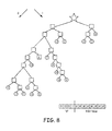
- FIG. 8 is a graphical representation of a truncated encoding tree according to one embodiment consistent with the teachings of the present invention.
- the star illustrates the starting point or starting node.
- Each oval represents the decimal equivalent of the indicated 8 bit (for this example) value and includes the set ⁇ 0, -1, 1, -2, 2, -3, 3, -4, 4, -5, 5, -6, 6, -7, 7, -8, 8).
- Each square node is a junction and each line indicates a bit value (0,1) depending upon direction. In this example, a line moving towards the left indicates a "0" and a line moving towards the right indicates a "1" with movement recognized from a higher position to a lower position, as illustrated. This convention is arbitrary and the reverse could be used instead (left is "1"; right is "0").
- This truncated coding tree provides the "codeword” for a given value.
- the codeword would be "00001".
- the value to be encoded equals "-3"
- the codeword would be "00001".
- the value may be "-3” and "00001" is encoded into memory.
- the encoded value for "0” is "11”; the encoded value for "1” is "101” and so on. As these are the most probable values they have the shortest codewords and achieve the greatest compression ratios.
- the most probable values fall within a relatively narrow band. This is generally captured by using values from -8 to 8; which corresponds to our 8 bit example. Thus, in a 12 bit example, the tree would encode values from -12 to 12. Therefore, the most probable and most frequently used values will have a codeword assigned. It should be appreciated that the values populating the tree are taken from the sample probability distribution. While taking the derivative waveform centers the probability distribution about zero, the values used are likely to be commonly employed. Of course, there may be various embodiments wherein the most probably values differ from those illustrated and the tree will be populated with those values instead.
- codewords defined by the tree are prefix free. That is, for this example, the 18 assigned codewords are unique and unambiguous.
- the codewords will vary from 2 bits to 8 bits and it would not be possible to decode a value from a variable length codeword in a stream of data absent this aspect. For example, according to FIG. 8 , if a codeword begins with "1" it can only represent ⁇ 0, -1, or 1 ⁇ . "11” can only represent “0”; “101” represents “1”; and "100” represents "-1”. As such, "10011” could not be a single codeword because it would be ambiguous whether that data set indicated the single codeword or represented "-1" followed by "0". When decoding the data, it is parsed until an unambiguous codeword is identified and the next bit begins the next codeword.
- codewords are provided for the decimal values of -8 to 8.
- the waveform is unlikely to swing that dramatically from point to point. Nevertheless, point to point variations will likely exceed 8 at times.
- the tree could be extended to provide codewords for all 256 values; however, in order to be unambiguous these codewords would become increasingly large with the largest having 256 bits.
- the present embodiment utilizes a truncated entropy encoder. That is, for any value not displayed on the tree, the actual 8 bit value is utilized with a prefix or exit code which is the codeword indicated by the "X" oval on the tree.
- the truncated entropy encoder illustrated by FIG. 8 indicates that codewords are provided for less than the complete set of potential data increments; thus the tree or data map is truncated.
- the codewords themselves are unambiguous, prefix free and one codeword is utilized to signal that a predetermined number of bits to follow are unencoded. In the illustration of FIG. 8 , this is represented by the populated 4 bit "X" value and the 8 bit place holder. This X node or value will be referred to as the prefix codeword. It should be appreciated that in other protocols, different values may be encoded depending upon probability and the X node may be provided at a different node either increasing or decreasing the required number of bits for the prefix codeword.
- systems using different resolution may be used with or without a corresponding expansion of the tree.
- various combinations may be employed. For example, other unique codewords could be created that indicate longer or shorter data to follow; or that other action is to be taken, such as error checking or the like.
- FIG. 9 is a waveform sample from a patient during ventricular tachycardia.
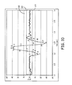
- FIG. 10 is a small portion (a QRS complex) of the derivative of the waveform of FIG. 9 and illustrates (as diamonds) the various points that are digitally sampled.
- a high probability band 300 is bounded by an upper limit 310 and a lower limit 320 and is centered about zero. The high probability band 300 simply visually indicates that any data point falling on or in that band will have a codeword for its value; thus, in this case the upper limit 310 is equal to 8, while the lower limit 320 is equal to -8.
- data point 1 will be presumed to be an encoded data point.
- the rule processor 220 evaluates data point 1 to determine whether data point 1 should have been encoded. Data point 1 was within the band 300 and should have been encoded. Thus, data point 2 is encoded by the encoder 225. Data point 2 appears to have the value of negative 8, thus the codeword would be "00000110", which is stored in memory 230.
- the rule processor 220 evaluates whether data point 2 should have been encoded. As data point 2 fell on or in the band 300, data point 2 should have been encoded. Thus, data point 3 is encoded even though it is outside of the band 300.
- the prefix codeword is employed ("X + 8 bit value for -24 (or 104)) which in this example is "00011101000.” This value is stored in memory 230 by the entropy encoder 225.
- the rule processor 220 evaluates whether data point 3 should have been encoded. Data point 3 was encoded, but should not have been in that in fell outside the band 300. Thus, data point 4 is not encoded.
- the rule processor 220 stores the 8 bit value of data point 4 directly in memory 230, bypassing the entropy encoder 225 (of FIG. 2 ).
- the rule processor 220 determines whether data point 6 should have been encoded and it should not have been (and was not); thus, data point 7 is not encoded despite falling within the band 300.
- Data point 8 will be encoded because data point 7 should have been; thus, data point 8 will have a 12 bit value.
- data point 14 will not be encoded because data point 13 should not have been.
- LEE linear predictive entropy encoding
- the above described truncated entropy encoding embodiment provides for an average codeword length of 3.4 for the normal sinus rhythm, 4.4 for atrial fibrillation, 3.9 for congestive heart failure and 3.4 for ventricular tachycardia.
- the shortest codeword will be 2 bits and the longest will be 12 bits.
- the lossless compression rates may be 4:1.
- Cardiac EGM data is effectively and efficiently stored in a reliable, real-time manner that allows for high resolution reconstruction of the sampled waveform.
- Other physiological signals are also well suited for this type of encoding.
- cardiac pressure data is typically cyclic and falls within a narrow dynamic range. Significant variation occurs when the patient changes environments (e.g., moves to a high altitude) and these infrequent variations are effectively managed by using the predictive linear encoding. Thereafter, the truncated entropy encoding may be used to achieve high compression ratios.
- any physiologic waveform or any waveform in general may be stored using the embodiments described herein.
- the truncated encoding tree ( FIG. 8 ) is defined and stored in memory in both the encoder and the decoder.
- the rule or algorithm for the linear predictive encoding is defined and stored in memory. For example, the current data point is assumed to be equal to the previous data point; the actual difference between the two (i.e., the error) is the value stored in memory.
- both the encoder and decoder need to have the same tree and rule(s); neither the tree nor the rule(s) necessarily must remain static. That is, adaptive Huffman encoding may be utilized to develop a patient specific tree based upon sampled data. Furthermore, this tree may be periodically changed based upon sampled data; therefore, the tree is dynamically changed as the underlying probability distribution changes.
- a new or updated tree may be generated after several thousand samples and passed to the decoder as appropriate.
- the linear predictive encoding rule(s) cold likewise be generated on a patient specific basis or updated dynamically. That is, as the sample data is collected and processed, a more accurate (i.e., smaller error values) rule (linear or non-linear) is derived. The new rule is then used on data subsequently collected.
- the dynamic creation and modification of the tree as well as the predictive encoding rule(s) would be most applicable in embodiments where the underlying signal may vary from source to source (e.g., patient to patient) but has some regularity or pattern within a given source over a useful time period.
- cardiac signals even within a single patient will likely have too much variability to benefit significantly from such dynamic modification, particularly on a real-time or streaming basis.
- the dynamic modification could be utilized to increase compression of the data.
- data that is stored in memory represents a sampled data point, an encoded data point, or an entropy encoded codeword for the same. That is, the stored value ultimately reflects a given sampled value of the relevant waveform. It should be appreciated that many other types of data may be stored by a device separate from the sampled waveform.
- various indicators or markers may be interleaved with the encoded data.
- MarkerChannel TM data is created and recorded by the device as an annotation of the events occurring within the sensed data.
- the events may be routine, such as a sensed atrial depolarization (A sense / P wave); a sensed ventricular depolarization (V sense / R wave); paced atrial event (AP); or paced ventricular event (VP).
- longer cardiac events such as, for example, atrial fibrillation (AF), ventricular tachycardia (VT) or the like are detected by the device through various algorithms. The initiation of theses events or at least when they are initially detected may likewise be annotated.
- the annotation of the data is performed by the microprocessor 120 ( Fig. 1 ) based on the data collected, in analog form or at any stage of the digital signal processing.
- Each device will typically record multiple channels of data. There may be an atrial channel sensing atrial events, one or two ventricular channels directly sensing ventricular events; other vectors between a given lead/electrode and an electrode positioned within the housing of the device (e.g., right ventricular ring electrode to housing); and any number of other sensed parameters such as pressure or impedance.
- the annotation data is stored within the recorded data stream for each channel. If the annotation data is stored separately, it must be correlated in time to the sensed data which requires additional memory usage.
- an exit code is provided. For example, with 8 bit resolution and 256 discrete intervals value "256" may be designated as the exit code.
- a sampled value that would equate to the interval 256 is assigned to 255; in other words values sensed at, e.g., the voltage corresponding to interval 256 are essentially rounded to the voltage of interval 255. This simply frees up one value to be used as the exit code.
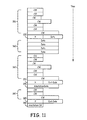
- FIG. 11 is a block diagram illustrating sequentially stored data points in memory. Initially, there are a series of data points encoded as variable length codewords 350. Data point 355 is an "X" codeword followed by an, e.g., 8 bit data value. Next, there are a series of non-entropy encoded data points 360, followed by another series of data points encoded as codewords 365. This simply represents a sample of the linear predictive encoding and entropy encoding as previously described.
- the data point 370 is the X codeword, again signifying that the data to immediately follow is not entropy encoded.
- the exit code is provided. This signifies that the next stored data point (or series of points) is an annotation, such as MarkerChannel TM data.
- the annotation data point 375 is provided and signifies a particular event has occurred, started, or stopped at this point in time or may be used to indicate any information relevant in time as determined by the algorithms stored within the device.
- Using an 8 bit example with a single word defining an annotation there are 256 possible annotations. Of course, by using more that one word, more annotations are possible.
- the prefix codeword from the truncated entropy encoding tree ( Fig. 8 ) is used in combination with an exit code to indicated interleaved annotations.
- annotation 390 is a codeword selected from the truncated entropy encoding tree ( Fig. 8 ).
- the particular values utilized to represent the annotation may be mapped accordingly.
- a codeword may be mapped to a given annotation. This will allow shorter values to be stored as annotations, which may be beneficial when certain annotations occur frequently.
- Using only the truncated entropy encoding tree will produce less possible annotations (e.g., 18), which may or may not be sufficient.
- codewords may be utilized for frequent annotations and the combination of the prefix codeword followed by a full-length word may be used for any other annotation not defined by the truncated entropy encoding tree.
- the prefix codeword (X) would be followed by the annotation exit code.
- the next data point would either be just a codeword (as illustrated) or another entry of the prefix codeword followed by the annotation data. This would represent a longer value (e.g., 12 bits in the 8 bit resolution example), but would be offset by the repetitive use of short codewords at other times.
- the relevant device such as IMD 100 not only collects/samples the waveforms and records some or all of this data into memory, it also analyzes the data to identify events. This may occur whether or not the data is annotated.
- Fig. 10 another embodiment of the present invention will be described. What is illustrated is a derivative of a sample QRS complex recorded from a single channel. As previously indicated, this is an arbitrary selection, centered on the QRS with a portion of the PQ segment and a portion of the ST segment illustrated. In processing such a waveform, the IMD 100 may identify the peak of the R wave (point 10, 11) as a means of detecting a ventricular event.
- the complex is detected and if appropriated, annotated.
- the entropy encoding compression is disabled upon the detection of one or more events, such as an atrial sense, atrial pace, ventricular sense, ventricular pace, or the onset of particular rhythms such as ventricular fibrillation or tachycardia. Whatever the process the IMD 100 identifies such events will be utilized to disable the entropy encoding compression.
- the compression will be disabled for a predetermined period of time relevant to the event, such as an averaged measured QRS duration for a given patient or an average value for a patient population. Alternatively, compression may be disabled for a predetermined number of samples or until the event concludes, as actually sensed by the device.
- the data points compressed generally all fall within the optimum band.
- the data points occurring during the events are not compressed, but there is also no need to use the prefix codeword, thus avoiding combinations that exceed the normal resolution value (e.g., avoid 12 bit word length for 8 bit data point).
- disabling compression when an event is detected may or may not result in a better overall compression and use of such a feature is selected accordingly. It should be appreciated that with multi-channel recording, a given event such as an atrial sense might only be sensed on one channel (e.g., the atrial lead). Thus, the other channels would continue to be compressed when this is the case, with only the relevant channel(s) disabling compression.
- FIG. 12 is a flowchart describing one method consistent with the teachings of the present invention.
- the relevant device such as an IMD 100 obtains an analog input representing a physiologic waveform.
- the device samples 400 this signal to obtain a digital representation of the waveform according to the parameters of the ADC being utilized.
- the digitized data is then subjected to linear predictive encoding 405. It should be appreciated that this may be occurring on a real time (data point by data point) basis or by buffering a certain amount of data.
- the linear predictive encoding 405 generates 410 a derivative of the sampled wave form. Thus, the first data point is left unchanged. Subsequent data points are replaced with a value equal to the difference between that data point and the value of the previous data point. At predetermined intervals, another data point is left intact to prevent the propagation of errors.
- a data point will be a value representing the sampled digital value of an analog waveform at a specific point in time or a derivative value of a particular sampled point.
- the data point is next subjected to a rule process 415 which evaluates whether the previous data point should or should not have been entropy encoded 420. If not, then the current data point is stored 425 in memory in an unencoded, uncompressed form (e.g., an 8 bit value as in the above example). Alternatively, if the previous data point should have been entropy encoded, then a codeword is substituted 430 for the value of the current data point.
- the determination of whether a given data point should or should not have been entropy encoded is based upon whether the previous value fell on or within an optimum band defined by a truncated entropy encoding map.
- the value of the data point (e.g., the "error") is compared with the truncated entropy map and a determination is made 435 as to whether a specific codeword is defined for this value. If so, then that code word is substituted 440 for that value and the code word is stored in memory. If not, then the prefix code word is utilized and the actual data point value (e.g., 8 bit value of difference between current sampled data point and value of immediately preceding data point) is added to or stored after the prefix codeword. Thus, the prefix code word and data point are stored 445 in memory.
- the actual data point value e.g., 8 bit value of difference between current sampled data point and value of immediately preceding data point
- the reverse process is performed. That is data is extracted from a device and decoded.
- the first value is known to be an unencoded starting value.
- the device then takes the next data point value and adds it to the first data point value to determine that actual waveform data point.
- the device determines whether the second data point (e.g., an error value) should have been encoded (based on its value). If so, then the third data point is a codeword and the codeword is decoded into an error value and the error value is added to the reconstructed second data point to obtain the third data point. If the second data point should not have been encoded, then the third data point is an actual value (e.g., 8 bit) and not a codeword.
- the process continues until the next unencoded data point wherein the process restarts. In this manner, data compression is achieved and the original waveform may be extracted without loss.
- FIG. 13 is a block diagram illustrating a decoding system.
- a receiver 500 is provided to receive the stored waveform data. This will typically involved receiving telemetered data from an implantable device either directly or via one or more intermediary devices.
- the receiver 500 may store data in a local memory 520 for subsequent processing or may send the data directly to a decoder 505 which parses the data.
- the initial data point and the appropriate subsequent data points are unencoded, non-derivative data of the original sampled waveform and these values are provided by a data output module 535 accordingly.
- a first word extractors 525 represent the module that identifies the first and subsequent unencoded, non-derivative data.
- the output from the data output module 535 may be directed to the memory 520 and/or another device for display, analysis or processing.
- the decoder 505 engages an entropy rule decoder.
- the entropy rule decoder 510 evaluates the value of a data point (a derivative point therefore representing a difference in value between adjacent data points) immediately prior to the data point currently being evaluated. If this value is such that is should have been entropy encoded, then the entropy rule decoder 510 determines that current data point is an entropy encoded codeword.
- the codeword is parsed by a codeword mapping module 530 that provides the value from a lookup table for the codeword. This will either provide a value or indicate that the value is contained within the following predetermined number of bits (e.g., a prefix codeword). Either way, a value of the derivative for the current data point is obtained and passed to the data extractor 515.
- the entropy rule encoder may determine that the previous data point should not have been entropy encoded. Thus, the current data point is not entropy encoded. As such, the value of this derivative data point is an unencoded (i.e., not entropy encoded) value of a predetermined length (e.g., 8 bits). This value is passed to the data extractor 515 accordingly.
- a predetermined length e.g. 8 bits
- the data extractor 515 functions in an opposite manner to the linear predictive encoder. That is, the data extractor 515 receives values for each data point representing its derivative. Thus, to reconstruct the waveform, the derivative value is added to the value of the previous data point to become the actual value for the current data point. The sampled waveform data is thereby reconstructed without loss and provided through data output 535 to memory 520, a display, or another device for manipulation, use or analysis.
- Fig. 14 is another example of a truncated entropy encoding tree. As previously addressed, the tree is a graphical representation of unambiguous codewords assigned to the highest probability values for a relevant waveform type.
- unitary increments were assigned codewords from a value of -8 to 8, inclusive of 0 and also include the prefix codeword X.
- Fig. 14 illustrates that the code words are not limited to unitary values, but may in fact represent a string or sequence of 2 or more values. The most liking occurring unitary values or sequences are given the shortest codewords. Accordingly, the sequence of a "1" followed by another "1" is as probable as a single occurrence of a "1" and is more probable than a "4". In other words, if identifiable sequences have a high probability they may assigned codewords; which, with a limited set of available codewords will displace some other value.
- the tree may be based upon generalized data. For example, over a wide patient population the sequence "1,0,1" might be quite common and hence incorporated into the tree stored in the memory of the encoder and decoder. Alternatively, the tree may be built upon collected data from a given source, such as a patient, shortly after implant. Finally, as noted above, the tree may be periodically updated through adaptive encoding. Thus, as data is actually collected and processed, repetitive sequences are detected and encoded. If, over time, this sequences changes, then the tree will continue to be updated as well.
- a codeword to represent a repetitive sequence of values will generally increase the compression ratio.
- a single 3 bit codeword is more efficient than four 3 bit codewords.
- not every repetitive sequence is efficiently replaced by a codeword.
- the efficiency gained by devoting a codeword to a sequence should be compared to the efficiency lost by either moving a unitary valued to a longer codeword (by either expanding the overall size of the tree or displacing another value) or removing that value from the tree entirely. As an example, if the sequence "0,0" occurred far more frequently than a single "0”, then it may be more efficient to have the codeword for "0,0" equal to the binary value 11 and shift "0" to a longer codeword.
- codewords may be utilized for unitary values or for sequences of two or more values that occur with sufficient frequency. While Figs. 8 and 14 provide a means to illustrate the assigned values, it should be appreciated that the overall assignment of values occurs due to a probability distribution. The particular sequences considered will be evaluated in the same manner in such a probability distribution and assigned codewords accordingly.
- the compression of sampled data with the present embodiments is lossless. That is, the reconstructed waveform will be identical to the sampled waveform after decoding. Often, the analysis of the collected waveforms requires a high degree of accuracy and lossy data compression (or loss due to other factors) could prevent accurate interpretation and the detection of significant events. On the other hand, noise and other extraneous variations in the collected waveform are also sampled and losslessly compressed.
- the IMD 100 is provided, in some embodiments, with a smoothing module 160 ( Fig. 1 ) to smooth or filter the data either prior to sampling or post-sampling.
- a smoothing module 160 Fig. 1
- generalized filtering techniques may be utilized. For example, a low pass filter may be provided to filter the analog data prior to sampling.
- Fig. 15 is a graph illustrating an exemplary waveform 600 with the linear analog signal in solid line and a plurality of sampled values indicated by diamonds.
- the X axis defines time (.3 seconds) and the Y axis defines the signal value in milivolts or rather, the sample values assigned to the same.
- the clinically significant portion of the illustrated waveform 600 is the QRS complex 610 that occurs approximately between data point 612 and data point 614.
- the overall width, shape, and amplitude of the QRS complex 610 may be important and if so, it would be undesirable to subject this portion of the waveform to a filtering function, such as a low pass filter.
- the data between data point 614 and the last illustrated data point 616 is relatively flat and the previously described encoding process would become even more effective if this portion of the data were smoothed. That is, the minor deflections noted are likely noise.
- the data points (614 to 616) could be replaced by zeroes. When parsed by the linear encoder, the value between the data points would be zero, which has the shortest available codeword. Further, if available, codewords for strings of zeros would also be available to increase compression. While there is a loss of some data, it is not significant to an analysis of the waveform 600.
- the IMD 100 While conceptually feasible, the selective application of filtering functions to portions of a waveform is challenging. That is, the IMD 100 would have to buffer data, analyze the waveforms, and selectively apply different filtering functions to different portions of the data. This is often not possible or practical with the time, memory and/or processing limitations of various implantable medical devices.
- one embodiment consistent with the teachings of the present invention provides a digital smoothing function that will smooth relatively stable portions of a waveform but leave more dynamic portions generally unchanged.
- the smoothing function permits near real time data processing with minimal buffering requirements.
- the smoothing module 160 analyzes each data point and determines variability between that data point and those adjacent to it to determine a variance. If the variance exceeds a predetermined value, then the data point value utilized is set equal to the sampled data point. If the variance is below the predetermined value, then a formula is applied to adjust the value of the data point. For example, an average or a weighted average is obtained between the data point and those immediately adjacent to it and the average (or weighted average) value is then utilized as the sampled value. This will smooth functions where there is relatively minor variation from point to point; however, where larger changes are present, the smoothing function has no effect.
- Fig. 16 is a flowchart describing the smoothing algorithm.
- the IMD 100 enables (700) the smoothing function.
- Three sampled data points (N-1, N, N+1) are collected and compared (705). This set of data points is referred to as an adjustment set and will vary for each data point. More (or fewer) points could be utilized; however, the more points utilized the greater the impact of the smoothing function on more signification portions of the waveform.
- the comparison (705) of the three data points is performed to calculate (710) a value for variability between them.
- V The variability value (V) is then compared (715) to a predetermined maximum value (MAX).
- MAX is equal to 5, but may be set to any value appropriate for the particular context.
- the sampled value for N is stored (720) in memory for data point S N .
- the value S N is used.
- the process then repeats for the next subsequent data point (e.g., N+1 is compared with N and (N+2)).
- V ⁇ MAX the value S n is adjusted (725) and then stored.
- S n is set to a weighted average.
- the weighted average is raised (ceil (C++ functionality)) or lowered (floor (C++ functionality)) to the next integer value.
- the value is rounded to an integer value representative of the digital sampling interval.
- the value calculated is then stored in memory (or buffered) for the data point S N .
- the process is repeated for the next data point N+1. In this manner, relatively stable portions of the waveform are smoothed while more dynamic portions are not; but this occurs on a point to point analysis so that the smoothing function itself is dynamically responsive.
- the smoothing function is applied to the sampled data prior to using the linear predictive encoding. This leads to a smoother waveform from which the predictive values are encoded and hence, a shift too shorter codewords when entropy coding is applied. It should be appreciated that the smoothing function could be applied after the predictive encoding process. In addition, the signal could be smoothed both before and after the encoding process.
- certain events may be used to initiate a period of time where entropy encoding is not utilized.
- entropy encoding is disabled for a typical QRS duration upon sensing a ventricular depolarization.
- disabling entropy encoding may be utilized in combination with the smoothing function.
- entropy encoding would be disabled for any data that does not pass through the smoothing filter.
- some predetermined number of higher variability data points must occur consecutively prior to disabling the entropy encoder either for those data points not parsed by the smoothing function or for a predetermined period of time.
Landscapes
- Health & Medical Sciences (AREA)
- Engineering & Computer Science (AREA)
- Life Sciences & Earth Sciences (AREA)
- Public Health (AREA)
- Animal Behavior & Ethology (AREA)
- Veterinary Medicine (AREA)
- General Health & Medical Sciences (AREA)
- Biomedical Technology (AREA)
- Nuclear Medicine, Radiotherapy & Molecular Imaging (AREA)
- Radiology & Medical Imaging (AREA)
- Cardiology (AREA)
- Physiology (AREA)
- Biophysics (AREA)
- Heart & Thoracic Surgery (AREA)
- Theoretical Computer Science (AREA)
- Measurement And Recording Of Electrical Phenomena And Electrical Characteristics Of The Living Body (AREA)
- Compression, Expansion, Code Conversion, And Decoders (AREA)
Claims (7)
- Implantierbare medizinische Vorrichtung (IMD), die Folgendes enthält:einen Speicher (124);einen Analog/Digital-Umsetzer (ADC) (206), der dafür ausgelegt ist, eine analoge Wellenform zu empfangen und die Wellenform in digitalisierte Daten umzusetzen;ein Glättungsfilter (160), das dafür ausgelegt ist, das umgesetzte Signal zu verarbeiten und jeden Datenpunkt als einen ersten Typ oder einen zweiten Typ zu klassifizieren und eine Glättungsfunktion auf den ersten Typ der klassifizierten Daten anzuwenden und einen umgesetzten Wert für den zweiten Typ der klassifizierten Daten zu sichern;ein Prädiktionscodierungsmodul (215), das betriebstechnisch mit dem ADC gekoppelt ist und dafür ausgelegt ist, einen codierten Wellenform-Datenpunkt für jeden äquivalenten Datenpunkt aus einer Teilmenge der digitalisierten Daten zu erzeugen; undein Entropiecodierungsmodul (225), das betriebstechnisch mit dem Prädiktionscodierer gekoppelt ist und dafür ausgelegt ist, einen codierten Wellenform-Datenpunkt selektiv durch ein Codewort für diesen Datenpunkt zu ersetzen;wobei das Glättungsfilter dafür ausgelegt ist, die Schwankung zwischen umgesetzten Datenpunkten in der Nähe von einem gegebenen Datenpunkt, der klassifiziert ist, zu bestimmen und den gegebenen Datenpunkt als den ersten Typ zu klassifizieren, wenn die Schwankung kleiner als ein vorgegebener Schwankungswert ist und in die zweite Gruppe zu klassifizieren, wenn die Schwankung gleich oder größer als der vorgegebene Schwankungswert ist.
- Verfahren, das umfasst:Ermitteln von umgesetzten Daten;Definieren eines Anpassungssatzes von Datenpunkten für jeden gegebenen Datenpunkt;Bestimmen eines Wertes für die Schwankung in dem Anpassungssatz; undGlätten des gegebenen Datenpunktes relativ zu dem Anpassungssatz, wenn die bestimmte Schwankung unterhalb eines vorgegebenen Maximums ist;wobei der Anpassungssatz den gegebenen Datenpunkt, einen ersten Datenpunkt, der dem gegebenen Datenpunkt unmittelbar vorausgeht, und einen zweiten Datenpunkt, der dem gegebenen Datenpunkt unmittelbar nachfolgt, beinhaltet; unddas Bestimmen der Schwankung das Messen eines Unterschiedes in einem Wert zwischen jedem Datenpunkt innerhalb des Anpassungssatzes beinhaltet und wobei das Bestimmen der Schwankung das Hinzufügen eines ersten absoluten Wertes eines Unterschiedes zwischen dem ersten Datenpunkt und dem gegebenen Datenpunkt und eines zweiten absoluten Wertes eines Unterschiedes zwischen dem zweiten Datenpunkt und dem gegebenen Datenpunkt beinhaltet.
- Verfahren nach Anspruch 2, wobei das Glätten des gegebenen Datenpunktes das Mitteln des Anpassungssatzes und das Setzen eines Wertes des gegebenen Datenpunktes für nachfolgendes Codieren auf den Mittelwert umfasst.
- Verfahren nach Anspruch 2, wobei das Glätten des gegebenen Datenpunktes das Ermitteln eines gewichteten Mittelwertes des Anpassungssatzes und das Setzen eines Wertes für nachfolgendes Codieren auf den Mittelwert umfasst.
- Verfahren nach Anspruch 3, das ferner das prädiktive Codieren der umgesetzten Daten nach dem selektiven Glätten der Daten umfasst und vorzugsweise ferner das selektive Bereitstellen von entropiecodierten Codewörtern für die prädiktiv codierten Daten, das auf einem verkürzten Entropie-Codewortsatz basiert, umfasst.
- Verfahren nach Anspruch 5, wobei das Entropiecodieren nur für geglättete Datenpunkte vorgesehen ist.
- Verfahren nach Anspruch 5, das ferner umfasst:Analysieren der umgesetzten Daten, wobei die umgesetzten Daten kardiale Wellenformen darstellen;Identifizieren von kardialen Ereignissen; undEntropiecodieren von Teilen der Daten in Abwesenheit von identifizierten kardialen Ereignissen, wobei das Bestimmen der Schwankung vorzugsweise für das Identifizieren von kardialen Ereignissen genutzt wird.
Applications Claiming Priority (2)
| Application Number | Priority Date | Filing Date | Title |
|---|---|---|---|
| US11/691,115 US8315709B2 (en) | 2007-03-26 | 2007-03-26 | System and method for smoothing sampled digital signals |
| PCT/US2008/057414 WO2008118702A1 (en) | 2007-03-26 | 2008-03-19 | System and method for smoothing sampled digital signals |
Publications (2)
| Publication Number | Publication Date |
|---|---|
| EP2135172A1 EP2135172A1 (de) | 2009-12-23 |
| EP2135172B1 true EP2135172B1 (de) | 2015-10-14 |
Family
ID=39596446
Family Applications (1)
| Application Number | Title | Priority Date | Filing Date |
|---|---|---|---|
| EP08732443.0A Not-in-force EP2135172B1 (de) | 2007-03-26 | 2008-03-19 | System und verfahren zum glätten abgetasteter digitalsignale |
Country Status (3)
| Country | Link |
|---|---|
| US (2) | US8315709B2 (de) |
| EP (1) | EP2135172B1 (de) |
| WO (1) | WO2008118702A1 (de) |
Families Citing this family (11)
| Publication number | Priority date | Publication date | Assignee | Title |
|---|---|---|---|---|
| US7798896B2 (en) | 2000-09-27 | 2010-09-21 | Milestone Entertainment Llc | Apparatus, systems and methods for implementing enhanced gaming and prizing parameters in an electronic environment |
| US9538922B2 (en) * | 2009-10-30 | 2017-01-10 | Medtronic, Inc. | Monitoring an interval within the cardiac cycle |
| WO2012050847A2 (en) | 2010-09-28 | 2012-04-19 | Masimo Corporation | Depth of consciousness monitor including oximeter |
| WO2012145073A1 (en) | 2011-04-22 | 2012-10-26 | Topera, Inc. | Basket style cardiac mapping catheter having spline bends for detection of cardiac rhythm disorders |
| GB2536163B (en) | 2013-10-17 | 2017-11-15 | Monica Healthcare Ltd | Apparatus and method for detecting an abdominal electrophysiological signal |
| US10154815B2 (en) | 2014-10-07 | 2018-12-18 | Masimo Corporation | Modular physiological sensors |
| TWI662948B (zh) * | 2018-08-10 | 2019-06-21 | 國立中央大學 | 無損心電訊號壓縮系統及方法 |
| US11218734B2 (en) * | 2019-02-12 | 2022-01-04 | Analog Devices, Inc. | Data compression implementation |
| JP7328768B2 (ja) * | 2019-02-14 | 2023-08-17 | 日本光電工業株式会社 | 心電波形解析装置 |
| US11744501B2 (en) | 2020-05-07 | 2023-09-05 | GE Precision Healthcare LLC | Multi-sensor patch |
| CN116500380A (zh) * | 2023-05-18 | 2023-07-28 | 国网陕西省电力有限公司电力科学研究院 | 数字采样波形光滑处理方法及系统 |
Family Cites Families (20)
| Publication number | Priority date | Publication date | Assignee | Title |
|---|---|---|---|---|
| US4449536A (en) | 1980-10-31 | 1984-05-22 | Sri International | Method and apparatus for digital data compression |
| US5379757A (en) * | 1990-08-28 | 1995-01-10 | Olympus Optical Co. Ltd. | Method of compressing endoscope image data based on image characteristics |
| US5139028A (en) * | 1990-10-26 | 1992-08-18 | Telectronics Pacing Systems, Inc. | Heart rejection monitoring apparatus and method |
| US5549649A (en) * | 1994-06-10 | 1996-08-27 | Pacesetter, Inc. | Programmable pacemaker including an atrial rate filter for deriving a filtered atrial rate used for switching pacing modes |
| FR2722313B1 (fr) | 1994-07-07 | 1997-04-25 | Ela Medical Sa | Procede de compression de donnees physiologiques, notamment d'active cardiaque, en particulier pour un enregistrement holter d'electrocardiogrammes ou d'electrogrammes |
| US5722999A (en) | 1995-08-02 | 1998-03-03 | Pacesetter, Inc. | System and method for storing and displaying historical medical data measured by an implantable medical device |
| DE69723899T2 (de) * | 1996-02-12 | 2004-06-17 | St. Jude Medical Ab | Taktempfindlicher Herzschrittmacher |
| JP4186242B2 (ja) * | 1997-12-26 | 2008-11-26 | ソニー株式会社 | 画像信号処理装置及び画像信号処理方法 |
| US7315815B1 (en) * | 1999-09-22 | 2008-01-01 | Microsoft Corporation | LPC-harmonic vocoder with superframe structure |
| SE0003480D0 (sv) * | 2000-09-27 | 2000-09-27 | St Jude Medical | Implantable heart stimulator |
| US7428436B2 (en) * | 2000-11-02 | 2008-09-23 | Cardiac Pacemakers, Inc. | Method for exclusion of ectopic events from heart rate variability metrics |
| US6719689B2 (en) | 2001-04-30 | 2004-04-13 | Medtronic, Inc. | Method and system for compressing and storing data in a medical device having limited storage |
| US6470065B1 (en) | 2001-07-13 | 2002-10-22 | Siemens Aktiengesellschaft | Apparatus for computer tomography scanning with compression of measurement data |
| US6810282B2 (en) * | 2001-10-25 | 2004-10-26 | GE Medical Systems Information Technolgies, Inc. | Method and apparatus for dynamically selecting an electrocardiogram compression process based on computerized analysis of cardiac rhythm and contour |
| US7022072B2 (en) * | 2001-12-27 | 2006-04-04 | Medtronic Minimed, Inc. | System for monitoring physiological characteristics |
| US7041061B2 (en) * | 2002-07-19 | 2006-05-09 | Cardiac Pacemakers, Inc. | Method and apparatus for quantification of cardiac wall motion asynchrony |
| CN100446560C (zh) * | 2003-01-10 | 2008-12-24 | 汤姆森特许公司 | 用于平滑在误差掩蔽期间产生的人为产物的解码器装置和方法 |
| US8725244B2 (en) * | 2004-03-16 | 2014-05-13 | Medtronic, Inc. | Determination of sleep quality for neurological disorders |
| US7288066B2 (en) | 2004-11-01 | 2007-10-30 | Medtronic, Inc. | Data compression method for implantable medical devices |
| WO2006121455A1 (en) * | 2005-05-10 | 2006-11-16 | The Salk Institute For Biological Studies | Dynamic signal processing |
-
2007
- 2007-03-26 US US11/691,115 patent/US8315709B2/en active Active
-
2008
- 2008-03-19 WO PCT/US2008/057414 patent/WO2008118702A1/en not_active Ceased
- 2008-03-19 EP EP08732443.0A patent/EP2135172B1/de not_active Not-in-force
-
2012
- 2012-08-06 US US13/567,188 patent/US9008789B2/en active Active
Also Published As
| Publication number | Publication date |
|---|---|
| US20120303329A1 (en) | 2012-11-29 |
| US8315709B2 (en) | 2012-11-20 |
| EP2135172A1 (de) | 2009-12-23 |
| WO2008118702A1 (en) | 2008-10-02 |
| US20080243207A1 (en) | 2008-10-02 |
| US9008789B2 (en) | 2015-04-14 |
Similar Documents
| Publication | Publication Date | Title |
|---|---|---|
| US7429938B1 (en) | Method of compressing waveform data with differential entropy based compression | |
| US7953492B2 (en) | System and method for annotating and compressing waveform data | |
| EP2135172B1 (de) | System und verfahren zum glätten abgetasteter digitalsignale | |
| US6599242B1 (en) | Method and apparatus for data compression of heart signals | |
| US7288066B2 (en) | Data compression method for implantable medical devices | |
| US6810282B2 (en) | Method and apparatus for dynamically selecting an electrocardiogram compression process based on computerized analysis of cardiac rhythm and contour | |
| US5836982A (en) | System and method of data compression and non-linear sampling for implantable and battery-powered devices | |
| US8849682B2 (en) | Adaptive data storage and download in a medical device | |
| US7904168B2 (en) | Differential entropy based data compression for waveforms | |
| CN1909831A (zh) | 心脏监视方法 | |
| EP2140553B1 (de) | Auf differenz-entropie basierende codierung von daten mit probabilistischen codes variabler länge | |
| Agarwal et al. | Input-feature correlated asynchronous analog to information converter for ECG monitoring | |
| US7933658B2 (en) | Differential entropy based data compression for waveforms | |
| Henry | Performance analysis for ECG signals using data warehouse architecture | |
| US6161043A (en) | Implantable cardiac device having event recording capability with compression | |
| US7764987B2 (en) | Signal processing apparatus for physiological signals | |
| US11456075B2 (en) | Implantable medical device having a coding module | |
| KR20090089039A (ko) | 주기성을 갖는 생체 신호 데이터의 실시간 압축 전송 및저장 방법과 이를 위한 심혈관 시스템 | |
| Ben-Romdhane et al. | Event-driven ECG sensor in healthcare devices for data transfer optimization | |
| Chang et al. | An efficient lossless ECG compression method using delta coding and optimal selective huffman coding | |
| Das et al. | Wavelet and PCA based ECG compression | |
| Saiful Islam | Compression of ECG signal based on its deviation from a standard reference using discrete cosine transform | |
| Bsoul | A novel ECG segmentation for compression using Fourier series approximation in e-health devices |
Legal Events
| Date | Code | Title | Description |
|---|---|---|---|
| PUAI | Public reference made under article 153(3) epc to a published international application that has entered the european phase |
Free format text: ORIGINAL CODE: 0009012 |
|
| 17P | Request for examination filed |
Effective date: 20091015 |
|
| AK | Designated contracting states |
Kind code of ref document: A1 Designated state(s): AT BE BG CH CY CZ DE DK EE ES FI FR GB GR HR HU IE IS IT LI LT LU LV MC MT NL NO PL PT RO SE SI SK TR |
|
| RIN1 | Information on inventor provided before grant (corrected) |
Inventor name: CORNDORF, ERIC D. |
|
| DAX | Request for extension of the european patent (deleted) | ||
| 17Q | First examination report despatched |
Effective date: 20120806 |
|
| REG | Reference to a national code |
Ref country code: DE Ref legal event code: R079 Ref document number: 602008040641 Country of ref document: DE Free format text: PREVIOUS MAIN CLASS: G06F0017000000 Ipc: A61N0001370000 |
|
| GRAP | Despatch of communication of intention to grant a patent |
Free format text: ORIGINAL CODE: EPIDOSNIGR1 |
|
| RIC1 | Information provided on ipc code assigned before grant |
Ipc: A61B 5/0432 20060101ALI20150410BHEP Ipc: A61B 5/00 20060101ALN20150410BHEP Ipc: H03M 7/40 20060101ALI20150410BHEP Ipc: A61B 5/0452 20060101ALI20150410BHEP Ipc: A61N 1/37 20060101AFI20150410BHEP Ipc: A61N 1/02 20060101ALI20150410BHEP |
|
| INTG | Intention to grant announced |
Effective date: 20150518 |
|
| GRAS | Grant fee paid |
Free format text: ORIGINAL CODE: EPIDOSNIGR3 |
|
| GRAA | (expected) grant |
Free format text: ORIGINAL CODE: 0009210 |
|
| AK | Designated contracting states |
Kind code of ref document: B1 Designated state(s): AT BE BG CH CY CZ DE DK EE ES FI FR GB GR HR HU IE IS IT LI LT LU LV MC MT NL NO PL PT RO SE SI SK TR |
|
| REG | Reference to a national code |
Ref country code: GB Ref legal event code: FG4D |
|
| REG | Reference to a national code |
Ref country code: AT Ref legal event code: REF Ref document number: 754654 Country of ref document: AT Kind code of ref document: T Effective date: 20151015 Ref country code: CH Ref legal event code: EP |
|
| REG | Reference to a national code |
Ref country code: IE Ref legal event code: FG4D |
|
| REG | Reference to a national code |
Ref country code: DE Ref legal event code: R096 Ref document number: 602008040641 Country of ref document: DE |
|
| REG | Reference to a national code |
Ref country code: NL Ref legal event code: MP Effective date: 20151014 |
|
| REG | Reference to a national code |
Ref country code: LT Ref legal event code: MG4D |
|
| REG | Reference to a national code |
Ref country code: AT Ref legal event code: MK05 Ref document number: 754654 Country of ref document: AT Kind code of ref document: T Effective date: 20151014 |
|
| REG | Reference to a national code |
Ref country code: FR Ref legal event code: PLFP Year of fee payment: 9 |
|
| PG25 | Lapsed in a contracting state [announced via postgrant information from national office to epo] |
Ref country code: ES Free format text: LAPSE BECAUSE OF FAILURE TO SUBMIT A TRANSLATION OF THE DESCRIPTION OR TO PAY THE FEE WITHIN THE PRESCRIBED TIME-LIMIT Effective date: 20151014 Ref country code: HR Free format text: LAPSE BECAUSE OF FAILURE TO SUBMIT A TRANSLATION OF THE DESCRIPTION OR TO PAY THE FEE WITHIN THE PRESCRIBED TIME-LIMIT Effective date: 20151014 Ref country code: IS Free format text: LAPSE BECAUSE OF FAILURE TO SUBMIT A TRANSLATION OF THE DESCRIPTION OR TO PAY THE FEE WITHIN THE PRESCRIBED TIME-LIMIT Effective date: 20160214 Ref country code: NL Free format text: LAPSE BECAUSE OF FAILURE TO SUBMIT A TRANSLATION OF THE DESCRIPTION OR TO PAY THE FEE WITHIN THE PRESCRIBED TIME-LIMIT Effective date: 20151014 Ref country code: LT Free format text: LAPSE BECAUSE OF FAILURE TO SUBMIT A TRANSLATION OF THE DESCRIPTION OR TO PAY THE FEE WITHIN THE PRESCRIBED TIME-LIMIT Effective date: 20151014 Ref country code: IT Free format text: LAPSE BECAUSE OF FAILURE TO SUBMIT A TRANSLATION OF THE DESCRIPTION OR TO PAY THE FEE WITHIN THE PRESCRIBED TIME-LIMIT Effective date: 20151014 Ref country code: NO Free format text: LAPSE BECAUSE OF FAILURE TO SUBMIT A TRANSLATION OF THE DESCRIPTION OR TO PAY THE FEE WITHIN THE PRESCRIBED TIME-LIMIT Effective date: 20160114 |
|
| PG25 | Lapsed in a contracting state [announced via postgrant information from national office to epo] |
Ref country code: PL Free format text: LAPSE BECAUSE OF FAILURE TO SUBMIT A TRANSLATION OF THE DESCRIPTION OR TO PAY THE FEE WITHIN THE PRESCRIBED TIME-LIMIT Effective date: 20151014 Ref country code: AT Free format text: LAPSE BECAUSE OF FAILURE TO SUBMIT A TRANSLATION OF THE DESCRIPTION OR TO PAY THE FEE WITHIN THE PRESCRIBED TIME-LIMIT Effective date: 20151014 Ref country code: LV Free format text: LAPSE BECAUSE OF FAILURE TO SUBMIT A TRANSLATION OF THE DESCRIPTION OR TO PAY THE FEE WITHIN THE PRESCRIBED TIME-LIMIT Effective date: 20151014 Ref country code: GR Free format text: LAPSE BECAUSE OF FAILURE TO SUBMIT A TRANSLATION OF THE DESCRIPTION OR TO PAY THE FEE WITHIN THE PRESCRIBED TIME-LIMIT Effective date: 20160115 Ref country code: PT Free format text: LAPSE BECAUSE OF FAILURE TO SUBMIT A TRANSLATION OF THE DESCRIPTION OR TO PAY THE FEE WITHIN THE PRESCRIBED TIME-LIMIT Effective date: 20160215 Ref country code: SE Free format text: LAPSE BECAUSE OF FAILURE TO SUBMIT A TRANSLATION OF THE DESCRIPTION OR TO PAY THE FEE WITHIN THE PRESCRIBED TIME-LIMIT Effective date: 20151014 Ref country code: FI Free format text: LAPSE BECAUSE OF FAILURE TO SUBMIT A TRANSLATION OF THE DESCRIPTION OR TO PAY THE FEE WITHIN THE PRESCRIBED TIME-LIMIT Effective date: 20151014 |
|
| REG | Reference to a national code |
Ref country code: DE Ref legal event code: R097 Ref document number: 602008040641 Country of ref document: DE |
|
| PG25 | Lapsed in a contracting state [announced via postgrant information from national office to epo] |
Ref country code: CZ Free format text: LAPSE BECAUSE OF FAILURE TO SUBMIT A TRANSLATION OF THE DESCRIPTION OR TO PAY THE FEE WITHIN THE PRESCRIBED TIME-LIMIT Effective date: 20151014 |
|
| PLBE | No opposition filed within time limit |
Free format text: ORIGINAL CODE: 0009261 |
|
| STAA | Information on the status of an ep patent application or granted ep patent |
Free format text: STATUS: NO OPPOSITION FILED WITHIN TIME LIMIT |
|
| PG25 | Lapsed in a contracting state [announced via postgrant information from national office to epo] |
Ref country code: RO Free format text: LAPSE BECAUSE OF FAILURE TO SUBMIT A TRANSLATION OF THE DESCRIPTION OR TO PAY THE FEE WITHIN THE PRESCRIBED TIME-LIMIT Effective date: 20151014 Ref country code: DK Free format text: LAPSE BECAUSE OF FAILURE TO SUBMIT A TRANSLATION OF THE DESCRIPTION OR TO PAY THE FEE WITHIN THE PRESCRIBED TIME-LIMIT Effective date: 20151014 Ref country code: EE Free format text: LAPSE BECAUSE OF FAILURE TO SUBMIT A TRANSLATION OF THE DESCRIPTION OR TO PAY THE FEE WITHIN THE PRESCRIBED TIME-LIMIT Effective date: 20151014 Ref country code: SK Free format text: LAPSE BECAUSE OF FAILURE TO SUBMIT A TRANSLATION OF THE DESCRIPTION OR TO PAY THE FEE WITHIN THE PRESCRIBED TIME-LIMIT Effective date: 20151014 Ref country code: BE Free format text: LAPSE BECAUSE OF NON-PAYMENT OF DUE FEES Effective date: 20160331 |
|
| 26N | No opposition filed |
Effective date: 20160715 |
|
| PG25 | Lapsed in a contracting state [announced via postgrant information from national office to epo] |
Ref country code: LU Free format text: LAPSE BECAUSE OF FAILURE TO SUBMIT A TRANSLATION OF THE DESCRIPTION OR TO PAY THE FEE WITHIN THE PRESCRIBED TIME-LIMIT Effective date: 20160319 Ref country code: MC Free format text: LAPSE BECAUSE OF FAILURE TO SUBMIT A TRANSLATION OF THE DESCRIPTION OR TO PAY THE FEE WITHIN THE PRESCRIBED TIME-LIMIT Effective date: 20151014 |
|
| REG | Reference to a national code |
Ref country code: CH Ref legal event code: PL |
|
| GBPC | Gb: european patent ceased through non-payment of renewal fee |
Effective date: 20160319 |
|
| PG25 | Lapsed in a contracting state [announced via postgrant information from national office to epo] |
Ref country code: SI Free format text: LAPSE BECAUSE OF FAILURE TO SUBMIT A TRANSLATION OF THE DESCRIPTION OR TO PAY THE FEE WITHIN THE PRESCRIBED TIME-LIMIT Effective date: 20151014 |
|
| REG | Reference to a national code |
Ref country code: IE Ref legal event code: MM4A |
|
| PG25 | Lapsed in a contracting state [announced via postgrant information from national office to epo] |
Ref country code: BE Free format text: LAPSE BECAUSE OF FAILURE TO SUBMIT A TRANSLATION OF THE DESCRIPTION OR TO PAY THE FEE WITHIN THE PRESCRIBED TIME-LIMIT Effective date: 20151014 |
|
| PG25 | Lapsed in a contracting state [announced via postgrant information from national office to epo] |
Ref country code: LI Free format text: LAPSE BECAUSE OF NON-PAYMENT OF DUE FEES Effective date: 20160331 Ref country code: CH Free format text: LAPSE BECAUSE OF NON-PAYMENT OF DUE FEES Effective date: 20160331 Ref country code: GB Free format text: LAPSE BECAUSE OF NON-PAYMENT OF DUE FEES Effective date: 20160319 Ref country code: IE Free format text: LAPSE BECAUSE OF NON-PAYMENT OF DUE FEES Effective date: 20160319 |
|
| REG | Reference to a national code |
Ref country code: FR Ref legal event code: PLFP Year of fee payment: 10 |
|
| PG25 | Lapsed in a contracting state [announced via postgrant information from national office to epo] |
Ref country code: MT Free format text: LAPSE BECAUSE OF FAILURE TO SUBMIT A TRANSLATION OF THE DESCRIPTION OR TO PAY THE FEE WITHIN THE PRESCRIBED TIME-LIMIT Effective date: 20151014 |
|
| REG | Reference to a national code |
Ref country code: FR Ref legal event code: PLFP Year of fee payment: 11 |
|
| PG25 | Lapsed in a contracting state [announced via postgrant information from national office to epo] |
Ref country code: HU Free format text: LAPSE BECAUSE OF FAILURE TO SUBMIT A TRANSLATION OF THE DESCRIPTION OR TO PAY THE FEE WITHIN THE PRESCRIBED TIME-LIMIT; INVALID AB INITIO Effective date: 20080319 Ref country code: CY Free format text: LAPSE BECAUSE OF FAILURE TO SUBMIT A TRANSLATION OF THE DESCRIPTION OR TO PAY THE FEE WITHIN THE PRESCRIBED TIME-LIMIT Effective date: 20151014 |
|
| PG25 | Lapsed in a contracting state [announced via postgrant information from national office to epo] |
Ref country code: MT Free format text: LAPSE BECAUSE OF FAILURE TO SUBMIT A TRANSLATION OF THE DESCRIPTION OR TO PAY THE FEE WITHIN THE PRESCRIBED TIME-LIMIT Effective date: 20160331 Ref country code: TR Free format text: LAPSE BECAUSE OF FAILURE TO SUBMIT A TRANSLATION OF THE DESCRIPTION OR TO PAY THE FEE WITHIN THE PRESCRIBED TIME-LIMIT Effective date: 20151014 |
|
| PG25 | Lapsed in a contracting state [announced via postgrant information from national office to epo] |
Ref country code: BG Free format text: LAPSE BECAUSE OF FAILURE TO SUBMIT A TRANSLATION OF THE DESCRIPTION OR TO PAY THE FEE WITHIN THE PRESCRIBED TIME-LIMIT Effective date: 20151014 |
|
| PGFP | Annual fee paid to national office [announced via postgrant information from national office to epo] |
Ref country code: DE Payment date: 20240220 Year of fee payment: 17 |
|
| PGFP | Annual fee paid to national office [announced via postgrant information from national office to epo] |
Ref country code: FR Payment date: 20240220 Year of fee payment: 17 |
|
| REG | Reference to a national code |
Ref country code: DE Ref legal event code: R119 Ref document number: 602008040641 Country of ref document: DE |
|
| PG25 | Lapsed in a contracting state [announced via postgrant information from national office to epo] |
Ref country code: DE Free format text: LAPSE BECAUSE OF NON-PAYMENT OF DUE FEES Effective date: 20251001 |
|
| PG25 | Lapsed in a contracting state [announced via postgrant information from national office to epo] |
Ref country code: FR Free format text: LAPSE BECAUSE OF NON-PAYMENT OF DUE FEES Effective date: 20250331 |