EP2134387B1 - Pumpeinheit zur enteralen oder parenteralen ernährung oder perfusion - Google Patents
Pumpeinheit zur enteralen oder parenteralen ernährung oder perfusion Download PDFInfo
- Publication number
- EP2134387B1 EP2134387B1 EP08706392A EP08706392A EP2134387B1 EP 2134387 B1 EP2134387 B1 EP 2134387B1 EP 08706392 A EP08706392 A EP 08706392A EP 08706392 A EP08706392 A EP 08706392A EP 2134387 B1 EP2134387 B1 EP 2134387B1
- Authority
- EP
- European Patent Office
- Prior art keywords
- pumping
- membrane
- pumping chamber
- pump
- slideway
- Prior art date
- Legal status (The legal status is an assumption and is not a legal conclusion. Google has not performed a legal analysis and makes no representation as to the accuracy of the status listed.)
- Not-in-force
Links
- 238000005086 pumping Methods 0.000 title claims description 58
- 235000016236 parenteral nutrition Nutrition 0.000 title description 4
- 230000010412 perfusion Effects 0.000 title 1
- 239000012528 membrane Substances 0.000 claims description 36
- 238000001802 infusion Methods 0.000 claims description 4
- 238000009434 installation Methods 0.000 claims description 2
- 230000036316 preload Effects 0.000 claims description 2
- 238000004891 communication Methods 0.000 description 7
- 230000005484 gravity Effects 0.000 description 5
- 238000011144 upstream manufacturing Methods 0.000 description 3
- 238000004140 cleaning Methods 0.000 description 2
- 230000005489 elastic deformation Effects 0.000 description 2
- 239000007788 liquid Substances 0.000 description 2
- 238000012423 maintenance Methods 0.000 description 2
- 239000000463 material Substances 0.000 description 2
- 239000004033 plastic Substances 0.000 description 2
- 239000012815 thermoplastic material Substances 0.000 description 2
- 239000011324 bead Substances 0.000 description 1
- 230000003749 cleanliness Effects 0.000 description 1
- 238000013461 design Methods 0.000 description 1
- 238000006073 displacement reaction Methods 0.000 description 1
- 239000000428 dust Substances 0.000 description 1
- 230000000694 effects Effects 0.000 description 1
- 239000011521 glass Substances 0.000 description 1
- 238000002347 injection Methods 0.000 description 1
- 239000007924 injection Substances 0.000 description 1
- 238000001746 injection moulding Methods 0.000 description 1
- 238000003801 milling Methods 0.000 description 1
- 230000002572 peristaltic effect Effects 0.000 description 1
- 230000002787 reinforcement Effects 0.000 description 1
- 230000000717 retained effect Effects 0.000 description 1
- 239000000243 solution Substances 0.000 description 1
- 230000001954 sterilising effect Effects 0.000 description 1
- 238000004659 sterilization and disinfection Methods 0.000 description 1
- 230000001225 therapeutic effect Effects 0.000 description 1
- 238000012549 training Methods 0.000 description 1
- 238000005406 washing Methods 0.000 description 1
Images

Classifications
-
- A—HUMAN NECESSITIES
- A61—MEDICAL OR VETERINARY SCIENCE; HYGIENE
- A61M—DEVICES FOR INTRODUCING MEDIA INTO, OR ONTO, THE BODY; DEVICES FOR TRANSDUCING BODY MEDIA OR FOR TAKING MEDIA FROM THE BODY; DEVICES FOR PRODUCING OR ENDING SLEEP OR STUPOR
- A61M5/00—Devices for bringing media into the body in a subcutaneous, intra-vascular or intramuscular way; Accessories therefor, e.g. filling or cleaning devices, arm-rests
- A61M5/14—Infusion devices, e.g. infusing by gravity; Blood infusion; Accessories therefor
- A61M5/1413—Modular systems comprising interconnecting elements
-
- A—HUMAN NECESSITIES
- A61—MEDICAL OR VETERINARY SCIENCE; HYGIENE
- A61M—DEVICES FOR INTRODUCING MEDIA INTO, OR ONTO, THE BODY; DEVICES FOR TRANSDUCING BODY MEDIA OR FOR TAKING MEDIA FROM THE BODY; DEVICES FOR PRODUCING OR ENDING SLEEP OR STUPOR
- A61M5/00—Devices for bringing media into the body in a subcutaneous, intra-vascular or intramuscular way; Accessories therefor, e.g. filling or cleaning devices, arm-rests
- A61M5/14—Infusion devices, e.g. infusing by gravity; Blood infusion; Accessories therefor
- A61M5/142—Pressure infusion, e.g. using pumps
- A61M5/14212—Pumping with an aspiration and an expulsion action
- A61M5/14216—Reciprocating piston type
-
- A—HUMAN NECESSITIES
- A61—MEDICAL OR VETERINARY SCIENCE; HYGIENE
- A61M—DEVICES FOR INTRODUCING MEDIA INTO, OR ONTO, THE BODY; DEVICES FOR TRANSDUCING BODY MEDIA OR FOR TAKING MEDIA FROM THE BODY; DEVICES FOR PRODUCING OR ENDING SLEEP OR STUPOR
- A61M5/00—Devices for bringing media into the body in a subcutaneous, intra-vascular or intramuscular way; Accessories therefor, e.g. filling or cleaning devices, arm-rests
- A61M5/14—Infusion devices, e.g. infusing by gravity; Blood infusion; Accessories therefor
- A61M5/142—Pressure infusion, e.g. using pumps
- A61M5/14212—Pumping with an aspiration and an expulsion action
- A61M5/14224—Diaphragm type
-
- A—HUMAN NECESSITIES
- A61—MEDICAL OR VETERINARY SCIENCE; HYGIENE
- A61M—DEVICES FOR INTRODUCING MEDIA INTO, OR ONTO, THE BODY; DEVICES FOR TRANSDUCING BODY MEDIA OR FOR TAKING MEDIA FROM THE BODY; DEVICES FOR PRODUCING OR ENDING SLEEP OR STUPOR
- A61M2205/00—General characteristics of the apparatus
- A61M2205/12—General characteristics of the apparatus with interchangeable cassettes forming partially or totally the fluid circuit
Definitions
- the present invention relates to a pumping unit for enteral or parenteral nutrition or infusion
- a pumping unit for enteral or parenteral nutrition or infusion comprising a disposable pumping chamber provided with an intake duct, a delivery duct and a deformable pumping membrane.
- a pusher for alternately deforming the deformable membrane said drive pusher being housed in a support housing, a wall of which has a retaining slide for engaging with sliding elements of the pumping chamber, this housing- support further having a passage opening of the drive pusher, stop means for determining the position of the pumping chamber along the retaining slide and for placing said pumping membrane in driving relation with said pusher 'training.
- EP-A-1400 254 describes a pumping unit identical to that of the preamble of claim 1.
- the main disadvantage of this device is its complexity and therefore its cost and reliability.
- the prestressing of the pumping membrane results from the displacement of the carriage in the same direction as that of moving the control pusher of this membrane, but in the opposite direction. So, if the position of the carriage in position pushed back to the frame is not perfectly exact, the stroke of the membrane and therefore the pumped volume will be variable.
- the object of the present invention is to remedy, at least in part, the problems posed by the aforementioned pumping systems.
- this invention relates to a pumping unit for enteral or parenteral nutrition or infusion according to claim 1.
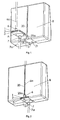
- the pumping unit that is the subject of the present invention essentially comprises two parts, a disposable pump A and a drive mechanism for this pump located in a support-case B.
- the disposable pumping chamber A is a pump whose pumping element is an annular membrane 1a, an embodiment of which is illustrated in more detail by the figure 3 .
- this single-use pump is essentially formed of a three-part enclosure 1, 2, 3, two parts 1, 3 forming the wall of the pumping chamber and an intermediate part 2.
- each of the wall portions 1, 3 comprises an intake duct 6 and a discharge duct 7.
- the wall portion 1 has a thinned portion forming an annular membrane 1a, surrounding a thicker actuating portion 1b.
- the thinned annular portion 1a serves as a pumping membrane whose central actuating portion thicker 1b is used to transmit to the annular membrane the force exerted by a drive member which, in this example, is a pusher formed by the movable core 4 of an electromagnet 5 driving the pump.
- the deformation of the membrane 1a must obviously remain within the limits of elastic deformation of the plastic material forming the wall portion 1.
- the intermediate portion 2 comprises a communication opening 2a for selectively communicating the upstream and downstream compartments of the pump.
- This communication opening 2a is arranged facing the thick central part 1b of the membrane and a valve valve 2b is located opposite an opening 2c opposite the inner end of the inlet duct 6 in the wall portion 1.
- the opening 2a is at the end of a depression, while the thicker central actuating portion 1b forms a projection which engages in the opening 2a.
- the intermediate portion 2 further comprises an annular projection 2d facing the wall portion 3, whose role will be explained below.
- the wall portion 3 comprises a seat concentric with the discharge pipe 7, for the positioning of a valve 10 for controlling the communication opening 2a of the intermediate part, which also serves as a device against free flow, in the purpose of preventing any flow of liquid when the single use is not inserted into the pump.
- This valve 10 is disposed between this communication opening 2a and the discharge pipe 7 of the pump. To prevent liquid from flowing by gravity through the pump, the valve 10 is applied against the opening 2a with a pressure of 4.10 4 Pa ⁇ 1.10 4 Pa.
- the wall portion 3 has an annular seat 3a for positioning the valve 10.
- This valve 10 is retained on the seat 3a by the annular projection 2d of the intermediate portion 2.
- the wall portion 3 further comprises a projection 3b located opposite of the check valve 2b of the admission duct 6, to prevent this valve 2b from being pressed against the inner face of the wall portion 3.
- the pump described above is designed to operate with great autonomy.
- a number of conditions have been met, both with regard to the pump itself and its driving device.
- the details relating to this pump and its drive device are described in the patent application.
- EP 07405078.2 to which one can refer for more details, these being not necessary to understand the present invention.
- the membrane 1a has a relatively small diameter of between 3 and 25 mm, advantageously around 16 mm so as to limit its actuating force, which is the product of the pressure P by the surface S. Given that it is preferably considered to actuate this membrane by an electromagnet low consumption, we chose a small size electromagnet.
- the stroke of the diaphragm 1a, driven by the pusher core 4 of the electromagnet, is preferably between 0.2 and 2 mm, advantageously of the order of 0.5 mm. Under these conditions, the stroke of the diaphragm 1a allows its direct drive by the pusher core 4 of the electromagnet and avoids any mechanical gear which substantially reduces the overall efficiency of the pump.
- the thickness of the elastic membrane 1a is between 0.1 and 0.7 mm, preferably of the order of 0.3 mm.
- thermoplastic material for the membrane 1a as for the wall part 1 of the pump enclosure, which makes it possible to produce the part 1 and the membrane 1a in a single injection operation.
- thermoplastic materials include PC, PVC, ABS, PP or PE in particular. The choice depends on the cost, accuracy and stability of the elastic characteristics after sterilization and storage over a maximum of three years.
- the PC is the material that best fits this specification.
- the lower face of the support housing B of the driving electromagnet 5 comprises a retaining slide 19, which extends over the entire width of the lower face of the support housing B and whose profile of the cross section can be advantageously dovetail forming two sliding shoes to about 45 ° to come into taken with two parallel edges of the walls 1, 3 of the pump chamber A, which constitute the sliding elements of this pumping chamber A.
- This retaining slide 19 may have any other suitable profile, adapted to that of the parallel edges of the walls 1, 3 of the pumping chamber A, to allow to press and maintain the outer face of the wall 1 of the disposable pumping chamber A applied against the bottom of the retaining slide 19.
- the deformable membrane 1a is subjected to a prestressing deformation in the rest position, in order to allow it to return sufficiently quickly to its rest position by its own elasticity after have been moved by the pusher core 4 of the electromagnet 5.
- the mere introduction of the pumping chamber A in the slideway 19 guarantees a perfectly reproducible accuracy.
- the slide is an element easily accessible and visible to ensure its cleanliness and durability of accuracy over time.
- a communication aperture 21 is formed in the bottom of the retaining slide 19 to allow the pusher core 4 of the electromagnet 5 to engage the thicker central portion 1b of the pumping chamber A. It is still possible to note that the retaining slide 19 crosses the entire width of the bottom wall of the housing-support B, which facilitates cleaning because the retaining slide opens outwardly at both ends, there is no recess in which dust could accumulate.
- the positioning and maintenance of the disposable pumping chamber A in the retaining slide 19 are obtained by clipping the flexible suction duct 6a or the discharge pipe 7a of the disposable pumping chamber A into a chute 20 formed in a wall of the housing-support B adjacent to the bottom wall in which is formed the retaining slide and whose width of the longitudinal opening giving access to the chute 20 is slightly narrower than the diameter of the duct 6a or 7a, so that a slight elastic deformation of the section of this duct 6a or 7a is necessary to introduce it into the chute 20 after which, the section of the flexible duct 6a or 7a resumes its initial shape, guaranteeing the maintenance of the pumping chamber A in the retaining slide 19 and the positioning of the thicker central portion 1b of the membrane 1a vis-à-vis the pusher core 4 of the electromagnet 5.
- the chute 20 at its base a portion 20a of larger diameter for receiving the portion 6 of the admission duct integral with the pump A.
- An ON-OFF switch 18 is arranged in the bottom of the slideway 19 to enable the electromagnet 5 to be switched on only when the pump A is engaged in the slideway 19.
- the electromagnet 5 then goes into the pump ready mode. .
- the user can then enter the control parameters of the pump using a control station (not shown).
- This switch 18 could also be located in the trough 20 or in its enlarged portion 20a, which would have the same effect of putting the electromagnet in ready to pump mode when the pump A is in place.
Landscapes
- Health & Medical Sciences (AREA)
- Vascular Medicine (AREA)
- Engineering & Computer Science (AREA)
- Anesthesiology (AREA)
- Biomedical Technology (AREA)
- Heart & Thoracic Surgery (AREA)
- Hematology (AREA)
- Life Sciences & Earth Sciences (AREA)
- Animal Behavior & Ethology (AREA)
- General Health & Medical Sciences (AREA)
- Public Health (AREA)
- Veterinary Medicine (AREA)
- Infusion, Injection, And Reservoir Apparatuses (AREA)
- Reciprocating Pumps (AREA)
Claims (4)
- Pumpeinheit zur enteralen oder parenteralen Ernährung oder zur Infusion mit einem Einwegpumpgehäuse (A), das einen Einlasskanal (6), einen Auslasskanal (7) und eine elastisch verformbare Pumpmembran (1a) aufweist, mit einem Stößel (4) zum abwechselnden Verformen der verformbaren Membran (1a), wobei der Antriebsstößel in einem Trägergehäuse (B) angeordnet ist, bei dem eine Wand eine Rückhalteschiene (19) aufweist, um mit den Gleitelementen des Pumpgehäuses (A) in Eingriff zu kommen, wobei das Trägergehäuse (B) weiterhin eine Durchgangsöffnung (21) für den Antriebsstößel (4) aufweist, mit Anschlagsmitteln (20) zum Festlegen der Stellung des Pumpgehäuses (A) entlang der Rückhalteschiene (19) und um die Pumpmembran (1a) in ein Antriebsverhältnis mit dem Antriebsstößel (4) zu bringen, dadurch gekennzeichnet, dass die Tiefe der Rückhalteschiene (19), die das Pumpgehäuse (A) aufnimmt, kleiner als die Höhe zwischen den Gleitelementen des Pumpgehäuses (A) und der Außenseite der Pumpmembran (1a) ist, so dass das Anordnen des Pumpgehäuses (A) in die Rückhalteschiene (19) die Pumpmembran (1a) automatisch unter eine bestimmte Vorspannung setzt.
- Pumpeinheit nach Anspruch 1, die Mittel für eine lösbare Befestigung (19, 20) des Pumpgehäuses (A) in der festgelegten Stellung entlang der Rückhalteschiene (19) aufweist.
- Pumpeinheit nach einem der vorangehenden Ansprüche, bei der eine Wand des Trägergehäuses (B), die benachbart zu der die Rückhalteschiene (19) aufweisenden Wand angeordnet ist, eine Rinne (20) für das Einrasten entweder des Einlasskanals (6) oder des Auslasskanals (7) aufweist, wobei diese Rinne (20) für das Einrasten dazu dient, die Stellung der verformbaren Membran (1a) in Bezug auf den Antriebsstößel (4) und der Mittel für die lösbare Befestigung des Pumpgehäuses entlang der Rückhalteschiene (19) festzulegen.
- Pumpeinheit nach einem der vorangehenden Ansprüche, bei der ein EIN-AUS-Schalter (18), um den Antriebsmechanismus (5) in einen Modus zu bringen, in dem er zum Pumpen bereit ist, auf dem Trägergehäuse (B) an einer Stelle angebracht ist, wo er durch das Anordnen des Pumpgehäuses (A) in der Rückhalteschiene (19) betätigbar ist.
Priority Applications (1)
| Application Number | Priority Date | Filing Date | Title |
|---|---|---|---|
| EP08706392A EP2134387B1 (de) | 2007-03-12 | 2008-03-07 | Pumpeinheit zur enteralen oder parenteralen ernährung oder perfusion |
Applications Claiming Priority (3)
| Application Number | Priority Date | Filing Date | Title |
|---|---|---|---|
| EP07405082A EP1970081A1 (de) | 2007-03-12 | 2007-03-12 | Pumpeinheit zur enteralen oder parenteralen Ernährung oder Infusion |
| EP08706392A EP2134387B1 (de) | 2007-03-12 | 2008-03-07 | Pumpeinheit zur enteralen oder parenteralen ernährung oder perfusion |
| PCT/CH2008/000094 WO2008110024A1 (fr) | 2007-03-12 | 2008-03-07 | Unite de pompage de nutrition enterale ou parenterale ou de perfusion |
Publications (2)
| Publication Number | Publication Date |
|---|---|
| EP2134387A1 EP2134387A1 (de) | 2009-12-23 |
| EP2134387B1 true EP2134387B1 (de) | 2012-10-31 |
Family
ID=38171768
Family Applications (2)
| Application Number | Title | Priority Date | Filing Date |
|---|---|---|---|
| EP07405082A Pending EP1970081A1 (de) | 2007-03-12 | 2007-03-12 | Pumpeinheit zur enteralen oder parenteralen Ernährung oder Infusion |
| EP08706392A Not-in-force EP2134387B1 (de) | 2007-03-12 | 2008-03-07 | Pumpeinheit zur enteralen oder parenteralen ernährung oder perfusion |
Family Applications Before (1)
| Application Number | Title | Priority Date | Filing Date |
|---|---|---|---|
| EP07405082A Pending EP1970081A1 (de) | 2007-03-12 | 2007-03-12 | Pumpeinheit zur enteralen oder parenteralen Ernährung oder Infusion |
Country Status (3)
| Country | Link |
|---|---|
| US (1) | US8328537B2 (de) |
| EP (2) | EP1970081A1 (de) |
| WO (1) | WO2008110024A1 (de) |
Families Citing this family (14)
| Publication number | Priority date | Publication date | Assignee | Title |
|---|---|---|---|---|
| EP1967223A1 (de) * | 2007-03-08 | 2008-09-10 | Jean-Denis Rochat | Pumpe zur enteralen, parenteralen Ernährung oder Infusion |
| CA2758073C (en) | 2009-05-06 | 2017-05-23 | Alcon Inc. | Multiple segmented peristaltic pump and cassette |
| US20110137231A1 (en) | 2009-12-08 | 2011-06-09 | Alcon Research, Ltd. | Phacoemulsification Hand Piece With Integrated Aspiration Pump |
| CH702437A1 (fr) * | 2009-12-23 | 2011-06-30 | Jean-Denis Rochat | Pompe volumetrique alternative a membrane pour usage medical. |
| CH702436A1 (fr) * | 2009-12-23 | 2011-06-30 | Jean-Denis Rochat | Pompe doseuse a usage medical. |
| CH702418A1 (fr) | 2009-12-23 | 2011-06-30 | Jean-Denis Rochat | Cassette jetable de pompe de perfusion à usage médical et son procédé de fabrication. |
| EP2874583B1 (de) | 2012-12-11 | 2017-09-06 | Alcon Research, Ltd. | Phakoemulsifikationshandstück mit integrierter absaug- und benetzungspumpe |
| US9962288B2 (en) | 2013-03-07 | 2018-05-08 | Novartis Ag | Active acoustic streaming in hand piece for occlusion surge mitigation |
| US9126219B2 (en) | 2013-03-15 | 2015-09-08 | Alcon Research, Ltd. | Acoustic streaming fluid ejector |
| US9915274B2 (en) | 2013-03-15 | 2018-03-13 | Novartis Ag | Acoustic pumps and systems |
| US9750638B2 (en) | 2013-03-15 | 2017-09-05 | Novartis Ag | Systems and methods for ocular surgery |
| US9545337B2 (en) | 2013-03-15 | 2017-01-17 | Novartis Ag | Acoustic streaming glaucoma drainage device |
| US9693896B2 (en) | 2013-03-15 | 2017-07-04 | Novartis Ag | Systems and methods for ocular surgery |
| US9714650B2 (en) | 2013-06-11 | 2017-07-25 | Matthew G. Morris, Jr. | Pumping system |
Family Cites Families (14)
| Publication number | Priority date | Publication date | Assignee | Title |
|---|---|---|---|---|
| US3976402A (en) * | 1974-07-15 | 1976-08-24 | Origo, Inc. | Intravenous delivery pump |
| US4181245A (en) * | 1978-02-17 | 1980-01-01 | Baxter Travenol Laboratories, Inc. | Casette for use with an I.V. infusion controller |
| US4303376A (en) * | 1979-07-09 | 1981-12-01 | Baxter Travenol Laboratories, Inc. | Flow metering cassette and controller |
| US4336800A (en) * | 1980-08-01 | 1982-06-29 | Oximetrix, Inc. | Intravenous metering device |
| US4557725A (en) * | 1984-05-04 | 1985-12-10 | Oximetrix, Inc. | I. V. Pump cassette |
| US4768547A (en) * | 1985-11-18 | 1988-09-06 | Critikon, Inc. | Parenteral solution pump assembly |
| US4927411A (en) * | 1987-05-01 | 1990-05-22 | Abbott Laboratories | Drive mechanism for disposable fluid infusion pumping cassette |
| US5868678A (en) * | 1993-06-30 | 1999-02-09 | Medex, Inc. | Two-part medical pressure transducer with diaphragm stand-offs |
| US5601420A (en) * | 1994-09-12 | 1997-02-11 | Ivac Medical Systems, Inc. | Interlock, latching, and retaining mechanism for an infusion pump |
| US5575632A (en) * | 1994-09-12 | 1996-11-19 | Ivac Medical Systems, Inc. | Engineered pumping segment |
| US5647852A (en) * | 1995-01-31 | 1997-07-15 | Zimmer, Inc. | Lavage system including a cassette assembly |
| SE520340C2 (sv) * | 2002-03-14 | 2003-06-24 | Billy Nilson | Ambulatorisk membranpump |
| US7258534B2 (en) * | 2003-09-22 | 2007-08-21 | Hospira, Inc. | Fluid delivery device identification and loading system |
| EP1967223A1 (de) | 2007-03-08 | 2008-09-10 | Jean-Denis Rochat | Pumpe zur enteralen, parenteralen Ernährung oder Infusion |
-
2007
- 2007-03-12 EP EP07405082A patent/EP1970081A1/de active Pending
-
2008
- 2008-03-07 EP EP08706392A patent/EP2134387B1/de not_active Not-in-force
- 2008-03-07 WO PCT/CH2008/000094 patent/WO2008110024A1/fr not_active Ceased
- 2008-03-07 US US12/531,278 patent/US8328537B2/en not_active Expired - Fee Related
Also Published As
| Publication number | Publication date |
|---|---|
| EP2134387A1 (de) | 2009-12-23 |
| US8328537B2 (en) | 2012-12-11 |
| EP1970081A1 (de) | 2008-09-17 |
| US20100130934A1 (en) | 2010-05-27 |
| WO2008110024A1 (fr) | 2008-09-18 |
Similar Documents
| Publication | Publication Date | Title |
|---|---|---|
| EP2134387B1 (de) | Pumpeinheit zur enteralen oder parenteralen ernährung oder perfusion | |
| EP0927306B1 (de) | Tragbare peristaltische pumpe | |
| EP0632732B1 (de) | Medikamenteninfusionspumpe | |
| JP6040155B2 (ja) | ポンプモジュール、ポンプベースモジュール及びポンプシステム | |
| FR2765686A1 (fr) | Ensemble et procede de distribution de liquide | |
| FR2985790A1 (fr) | Pompe microdoseuse et son procede de fabrication | |
| EP3869993B1 (de) | Hairstyling-gerät mit einer flüssigkeitsentleerungsvorrichtung | |
| WO1998011350A1 (fr) | Pompe peristaltique miniature | |
| WO2003073953A1 (fr) | Dispositif de commutation pour liquides d'irrigation d'une piece a main dentaire | |
| EP4249750B1 (de) | Abgedichtete peristaltische pumpe für elektrisches haushaltsgerät | |
| FR2962986A1 (fr) | Dispositif pour distribuer un liquide, et procede de fabrication d'un tel dispositif. | |
| FR3102811A1 (fr) | Pompe péristaltique à corps de pompe monobloc et assemblage facilité | |
| EP2131895B1 (de) | Perfusions- oder enterale/parenterale ernährungspumpe | |
| FR2801955A1 (fr) | Soupape de contre-pression a aeration automatique | |
| FR2946836A1 (fr) | Ensemble de distribution comportant au moins un dispositif de distribution pour un systeme pour nourrir des animaux. | |
| EP3626137B1 (de) | Drehschüttelvorrichtung für getränkezubereitungsmaschine, die mit einer magnetischen kupplungsvorrichtung ausgestattet ist | |
| EP0932423A2 (de) | Miniaturisierte perestaltikpumpe zur medizinischen anwendung | |
| EP3086826B1 (de) | Hydraulikaggregat eines generators von gepulsten oder ungepulsten mittel- und hochdruckstrahlen | |
| WO2004076069A2 (fr) | Distributeur de produit fluide | |
| EP1596994B1 (de) | Flüssigkeitsabgabevorrichtung | |
| EP2247856A2 (de) | Fluidkanalstruktur und kassette für eine schlauchpumpe | |
| EP0211734B1 (de) | Dosierpumpe | |
| FR2883358A1 (fr) | Bloc-pompe | |
| CH579715A5 (en) | Metering pump with pinch roller and flexible tube - formed from flat profile with longitudinal retaining flanges |
Legal Events
| Date | Code | Title | Description |
|---|---|---|---|
| PUAI | Public reference made under article 153(3) epc to a published international application that has entered the european phase |
Free format text: ORIGINAL CODE: 0009012 |
|
| 17P | Request for examination filed |
Effective date: 20090921 |
|
| AK | Designated contracting states |
Kind code of ref document: A1 Designated state(s): AT BE BG CH CY CZ DE DK EE ES FI FR GB GR HR HU IE IS IT LI LT LU LV MC MT NL NO PL PT RO SE SI SK TR |
|
| DAX | Request for extension of the european patent (deleted) | ||
| GRAP | Despatch of communication of intention to grant a patent |
Free format text: ORIGINAL CODE: EPIDOSNIGR1 |
|
| GRAS | Grant fee paid |
Free format text: ORIGINAL CODE: EPIDOSNIGR3 |
|
| GRAA | (expected) grant |
Free format text: ORIGINAL CODE: 0009210 |
|
| AK | Designated contracting states |
Kind code of ref document: B1 Designated state(s): AT BE BG CH CY CZ DE DK EE ES FI FR GB GR HR HU IE IS IT LI LT LU LV MC MT NL NO PL PT RO SE SI SK TR |
|
| REG | Reference to a national code |
Ref country code: CH Ref legal event code: EP Ref country code: GB Ref legal event code: FG4D Free format text: NOT ENGLISH |
|
| REG | Reference to a national code |
Ref country code: AT Ref legal event code: REF Ref document number: 581637 Country of ref document: AT Kind code of ref document: T Effective date: 20121115 |
|
| REG | Reference to a national code |
Ref country code: IE Ref legal event code: FG4D Free format text: LANGUAGE OF EP DOCUMENT: FRENCH |
|
| REG | Reference to a national code |
Ref country code: DE Ref legal event code: R096 Ref document number: 602008019767 Country of ref document: DE Effective date: 20121227 |
|
| REG | Reference to a national code |
Ref country code: AT Ref legal event code: MK05 Ref document number: 581637 Country of ref document: AT Kind code of ref document: T Effective date: 20121031 |
|
| REG | Reference to a national code |
Ref country code: LT Ref legal event code: MG4D |
|
| REG | Reference to a national code |
Ref country code: NL Ref legal event code: VDEP Effective date: 20121031 |
|
| PG25 | Lapsed in a contracting state [announced via postgrant information from national office to epo] |
Ref country code: LT Free format text: LAPSE BECAUSE OF FAILURE TO SUBMIT A TRANSLATION OF THE DESCRIPTION OR TO PAY THE FEE WITHIN THE PRESCRIBED TIME-LIMIT Effective date: 20121031 Ref country code: SE Free format text: LAPSE BECAUSE OF FAILURE TO SUBMIT A TRANSLATION OF THE DESCRIPTION OR TO PAY THE FEE WITHIN THE PRESCRIBED TIME-LIMIT Effective date: 20121031 Ref country code: ES Free format text: LAPSE BECAUSE OF FAILURE TO SUBMIT A TRANSLATION OF THE DESCRIPTION OR TO PAY THE FEE WITHIN THE PRESCRIBED TIME-LIMIT Effective date: 20130211 Ref country code: NO Free format text: LAPSE BECAUSE OF FAILURE TO SUBMIT A TRANSLATION OF THE DESCRIPTION OR TO PAY THE FEE WITHIN THE PRESCRIBED TIME-LIMIT Effective date: 20130131 Ref country code: HR Free format text: LAPSE BECAUSE OF FAILURE TO SUBMIT A TRANSLATION OF THE DESCRIPTION OR TO PAY THE FEE WITHIN THE PRESCRIBED TIME-LIMIT Effective date: 20121031 Ref country code: FI Free format text: LAPSE BECAUSE OF FAILURE TO SUBMIT A TRANSLATION OF THE DESCRIPTION OR TO PAY THE FEE WITHIN THE PRESCRIBED TIME-LIMIT Effective date: 20121031 Ref country code: IS Free format text: LAPSE BECAUSE OF FAILURE TO SUBMIT A TRANSLATION OF THE DESCRIPTION OR TO PAY THE FEE WITHIN THE PRESCRIBED TIME-LIMIT Effective date: 20130228 Ref country code: NL Free format text: LAPSE BECAUSE OF FAILURE TO SUBMIT A TRANSLATION OF THE DESCRIPTION OR TO PAY THE FEE WITHIN THE PRESCRIBED TIME-LIMIT Effective date: 20121031 |
|
| PG25 | Lapsed in a contracting state [announced via postgrant information from national office to epo] |
Ref country code: CY Free format text: LAPSE BECAUSE OF FAILURE TO SUBMIT A TRANSLATION OF THE DESCRIPTION OR TO PAY THE FEE WITHIN THE PRESCRIBED TIME-LIMIT Effective date: 20121031 Ref country code: LV Free format text: LAPSE BECAUSE OF FAILURE TO SUBMIT A TRANSLATION OF THE DESCRIPTION OR TO PAY THE FEE WITHIN THE PRESCRIBED TIME-LIMIT Effective date: 20121031 Ref country code: GR Free format text: LAPSE BECAUSE OF FAILURE TO SUBMIT A TRANSLATION OF THE DESCRIPTION OR TO PAY THE FEE WITHIN THE PRESCRIBED TIME-LIMIT Effective date: 20130201 Ref country code: PT Free format text: LAPSE BECAUSE OF FAILURE TO SUBMIT A TRANSLATION OF THE DESCRIPTION OR TO PAY THE FEE WITHIN THE PRESCRIBED TIME-LIMIT Effective date: 20130228 Ref country code: PL Free format text: LAPSE BECAUSE OF FAILURE TO SUBMIT A TRANSLATION OF THE DESCRIPTION OR TO PAY THE FEE WITHIN THE PRESCRIBED TIME-LIMIT Effective date: 20121031 Ref country code: SI Free format text: LAPSE BECAUSE OF FAILURE TO SUBMIT A TRANSLATION OF THE DESCRIPTION OR TO PAY THE FEE WITHIN THE PRESCRIBED TIME-LIMIT Effective date: 20121031 |
|
| PG25 | Lapsed in a contracting state [announced via postgrant information from national office to epo] |
Ref country code: AT Free format text: LAPSE BECAUSE OF FAILURE TO SUBMIT A TRANSLATION OF THE DESCRIPTION OR TO PAY THE FEE WITHIN THE PRESCRIBED TIME-LIMIT Effective date: 20121031 |
|
| PG25 | Lapsed in a contracting state [announced via postgrant information from national office to epo] |
Ref country code: EE Free format text: LAPSE BECAUSE OF FAILURE TO SUBMIT A TRANSLATION OF THE DESCRIPTION OR TO PAY THE FEE WITHIN THE PRESCRIBED TIME-LIMIT Effective date: 20121031 Ref country code: DK Free format text: LAPSE BECAUSE OF FAILURE TO SUBMIT A TRANSLATION OF THE DESCRIPTION OR TO PAY THE FEE WITHIN THE PRESCRIBED TIME-LIMIT Effective date: 20121031 Ref country code: SK Free format text: LAPSE BECAUSE OF FAILURE TO SUBMIT A TRANSLATION OF THE DESCRIPTION OR TO PAY THE FEE WITHIN THE PRESCRIBED TIME-LIMIT Effective date: 20121031 Ref country code: BG Free format text: LAPSE BECAUSE OF FAILURE TO SUBMIT A TRANSLATION OF THE DESCRIPTION OR TO PAY THE FEE WITHIN THE PRESCRIBED TIME-LIMIT Effective date: 20130131 Ref country code: CZ Free format text: LAPSE BECAUSE OF FAILURE TO SUBMIT A TRANSLATION OF THE DESCRIPTION OR TO PAY THE FEE WITHIN THE PRESCRIBED TIME-LIMIT Effective date: 20121031 |
|
| PG25 | Lapsed in a contracting state [announced via postgrant information from national office to epo] |
Ref country code: RO Free format text: LAPSE BECAUSE OF FAILURE TO SUBMIT A TRANSLATION OF THE DESCRIPTION OR TO PAY THE FEE WITHIN THE PRESCRIBED TIME-LIMIT Effective date: 20121031 Ref country code: IT Free format text: LAPSE BECAUSE OF FAILURE TO SUBMIT A TRANSLATION OF THE DESCRIPTION OR TO PAY THE FEE WITHIN THE PRESCRIBED TIME-LIMIT Effective date: 20121031 |
|
| PLBE | No opposition filed within time limit |
Free format text: ORIGINAL CODE: 0009261 |
|
| STAA | Information on the status of an ep patent application or granted ep patent |
Free format text: STATUS: NO OPPOSITION FILED WITHIN TIME LIMIT |
|
| BERE | Be: lapsed |
Owner name: ROCHAT, JEAN-DENIS Effective date: 20130331 |
|
| 26N | No opposition filed |
Effective date: 20130801 |
|
| PG25 | Lapsed in a contracting state [announced via postgrant information from national office to epo] |
Ref country code: MC Free format text: LAPSE BECAUSE OF NON-PAYMENT OF DUE FEES Effective date: 20130331 |
|
| REG | Reference to a national code |
Ref country code: DE Ref legal event code: R097 Ref document number: 602008019767 Country of ref document: DE Effective date: 20130801 |
|
| REG | Reference to a national code |
Ref country code: IE Ref legal event code: MM4A |
|
| PG25 | Lapsed in a contracting state [announced via postgrant information from national office to epo] |
Ref country code: IE Free format text: LAPSE BECAUSE OF NON-PAYMENT OF DUE FEES Effective date: 20130307 Ref country code: BE Free format text: LAPSE BECAUSE OF NON-PAYMENT OF DUE FEES Effective date: 20130331 |
|
| PG25 | Lapsed in a contracting state [announced via postgrant information from national office to epo] |
Ref country code: MT Free format text: LAPSE BECAUSE OF FAILURE TO SUBMIT A TRANSLATION OF THE DESCRIPTION OR TO PAY THE FEE WITHIN THE PRESCRIBED TIME-LIMIT Effective date: 20121031 |
|
| PG25 | Lapsed in a contracting state [announced via postgrant information from national office to epo] |
Ref country code: TR Free format text: LAPSE BECAUSE OF FAILURE TO SUBMIT A TRANSLATION OF THE DESCRIPTION OR TO PAY THE FEE WITHIN THE PRESCRIBED TIME-LIMIT Effective date: 20121031 |
|
| PG25 | Lapsed in a contracting state [announced via postgrant information from national office to epo] |
Ref country code: HU Free format text: LAPSE BECAUSE OF FAILURE TO SUBMIT A TRANSLATION OF THE DESCRIPTION OR TO PAY THE FEE WITHIN THE PRESCRIBED TIME-LIMIT; INVALID AB INITIO Effective date: 20080307 Ref country code: LU Free format text: LAPSE BECAUSE OF NON-PAYMENT OF DUE FEES Effective date: 20130307 |
|
| REG | Reference to a national code |
Ref country code: FR Ref legal event code: PLFP Year of fee payment: 8 |
|
| REG | Reference to a national code |
Ref country code: FR Ref legal event code: PLFP Year of fee payment: 9 |
|
| REG | Reference to a national code |
Ref country code: FR Ref legal event code: PLFP Year of fee payment: 10 |
|
| REG | Reference to a national code |
Ref country code: FR Ref legal event code: PLFP Year of fee payment: 11 |
|
| PGFP | Annual fee paid to national office [announced via postgrant information from national office to epo] |
Ref country code: FR Payment date: 20190320 Year of fee payment: 12 Ref country code: DE Payment date: 20190220 Year of fee payment: 12 Ref country code: GB Payment date: 20190325 Year of fee payment: 12 Ref country code: CH Payment date: 20190326 Year of fee payment: 12 |
|
| REG | Reference to a national code |
Ref country code: CH Ref legal event code: NV Representative=s name: INVENTION ANGELS, DANIEL STONA, CH |
|
| REG | Reference to a national code |
Ref country code: DE Ref legal event code: R119 Ref document number: 602008019767 Country of ref document: DE |
|
| REG | Reference to a national code |
Ref country code: CH Ref legal event code: PL |
|
| PG25 | Lapsed in a contracting state [announced via postgrant information from national office to epo] |
Ref country code: FR Free format text: LAPSE BECAUSE OF NON-PAYMENT OF DUE FEES Effective date: 20200331 Ref country code: LI Free format text: LAPSE BECAUSE OF NON-PAYMENT OF DUE FEES Effective date: 20200331 Ref country code: DE Free format text: LAPSE BECAUSE OF NON-PAYMENT OF DUE FEES Effective date: 20201001 Ref country code: CH Free format text: LAPSE BECAUSE OF NON-PAYMENT OF DUE FEES Effective date: 20200331 |
|
| GBPC | Gb: european patent ceased through non-payment of renewal fee |
Effective date: 20200307 |
|
| PG25 | Lapsed in a contracting state [announced via postgrant information from national office to epo] |
Ref country code: GB Free format text: LAPSE BECAUSE OF NON-PAYMENT OF DUE FEES Effective date: 20200307 |