EP2133940B1 - Venting plug for stationary batteries, with blast-resistant protection and unlimited, automatic topping-up system, and topping-up assembly employing said plug - Google Patents
Venting plug for stationary batteries, with blast-resistant protection and unlimited, automatic topping-up system, and topping-up assembly employing said plug Download PDFInfo
- Publication number
- EP2133940B1 EP2133940B1 EP08425416A EP08425416A EP2133940B1 EP 2133940 B1 EP2133940 B1 EP 2133940B1 EP 08425416 A EP08425416 A EP 08425416A EP 08425416 A EP08425416 A EP 08425416A EP 2133940 B1 EP2133940 B1 EP 2133940B1
- Authority
- EP
- European Patent Office
- Prior art keywords
- topping
- plug
- support body
- venting plug
- bowl
- Prior art date
- Legal status (The legal status is an assumption and is not a legal conclusion. Google has not performed a legal analysis and makes no representation as to the accuracy of the status listed.)
- Not-in-force
Links
- 238000013022 venting Methods 0.000 title claims abstract description 13
- 239000003792 electrolyte Substances 0.000 claims abstract description 21
- 239000007788 liquid Substances 0.000 claims abstract description 13
- 239000007789 gas Substances 0.000 claims abstract description 6
- 230000004888 barrier function Effects 0.000 claims abstract 2
- 238000001914 filtration Methods 0.000 claims abstract 2
- 239000000919 ceramic Substances 0.000 claims description 8
- 239000000463 material Substances 0.000 claims description 8
- 239000004033 plastic Substances 0.000 claims description 8
- 229920003023 plastic Polymers 0.000 claims description 8
- 230000008878 coupling Effects 0.000 claims description 6
- 238000010168 coupling process Methods 0.000 claims description 6
- 238000005859 coupling reaction Methods 0.000 claims description 6
- 229910010293 ceramic material Inorganic materials 0.000 claims 1
- 238000004891 communication Methods 0.000 abstract description 3
- 230000000630 rising effect Effects 0.000 abstract 1
- XLYOFNOQVPJJNP-UHFFFAOYSA-N water Substances O XLYOFNOQVPJJNP-UHFFFAOYSA-N 0.000 description 7
- 238000000034 method Methods 0.000 description 6
- 239000000523 sample Substances 0.000 description 6
- 239000012153 distilled water Substances 0.000 description 5
- 238000003466 welding Methods 0.000 description 5
- 239000001257 hydrogen Substances 0.000 description 4
- 229910052739 hydrogen Inorganic materials 0.000 description 4
- UFHFLCQGNIYNRP-UHFFFAOYSA-N Hydrogen Chemical compound [H][H] UFHFLCQGNIYNRP-UHFFFAOYSA-N 0.000 description 3
- 239000004698 Polyethylene Substances 0.000 description 2
- 230000000712 assembly Effects 0.000 description 2
- 238000000429 assembly Methods 0.000 description 2
- QVGXLLKOCUKJST-UHFFFAOYSA-N atomic oxygen Chemical compound [O] QVGXLLKOCUKJST-UHFFFAOYSA-N 0.000 description 2
- 238000010276 construction Methods 0.000 description 2
- 239000008151 electrolyte solution Substances 0.000 description 2
- 238000012423 maintenance Methods 0.000 description 2
- 239000001301 oxygen Substances 0.000 description 2
- 229910052760 oxygen Inorganic materials 0.000 description 2
- -1 polyethylene Polymers 0.000 description 2
- 229920000573 polyethylene Polymers 0.000 description 2
- 229910000978 Pb alloy Inorganic materials 0.000 description 1
- QAOWNCQODCNURD-UHFFFAOYSA-N Sulfuric acid Chemical compound OS(O)(=O)=O QAOWNCQODCNURD-UHFFFAOYSA-N 0.000 description 1
- 239000002253 acid Substances 0.000 description 1
- 229910052787 antimony Inorganic materials 0.000 description 1
- 238000005422 blasting Methods 0.000 description 1
- 230000006835 compression Effects 0.000 description 1
- 238000007906 compression Methods 0.000 description 1
- 229910052593 corundum Inorganic materials 0.000 description 1
- 239000010431 corundum Substances 0.000 description 1
- 230000001419 dependent effect Effects 0.000 description 1
- 238000005474 detonation Methods 0.000 description 1
- 238000007599 discharging Methods 0.000 description 1
- 239000002360 explosive Substances 0.000 description 1
- 239000003365 glass fiber Substances 0.000 description 1
- 150000002431 hydrogen Chemical class 0.000 description 1
- 238000009434 installation Methods 0.000 description 1
- 238000012544 monitoring process Methods 0.000 description 1
- 238000000465 moulding Methods 0.000 description 1
- 238000009738 saturating Methods 0.000 description 1
- 238000007650 screen-printing Methods 0.000 description 1
- HBMJWWWQQXIZIP-UHFFFAOYSA-N silicon carbide Chemical compound [Si+]#[C-] HBMJWWWQQXIZIP-UHFFFAOYSA-N 0.000 description 1
- 229910010271 silicon carbide Inorganic materials 0.000 description 1
- 239000000243 solution Substances 0.000 description 1
- 235000011149 sulphuric acid Nutrition 0.000 description 1
- 239000001117 sulphuric acid Substances 0.000 description 1
- 238000012546 transfer Methods 0.000 description 1
- 238000013519 translation Methods 0.000 description 1
- 230000000007 visual effect Effects 0.000 description 1
Images





Classifications
-
- H—ELECTRICITY
- H01—ELECTRIC ELEMENTS
- H01M—PROCESSES OR MEANS, e.g. BATTERIES, FOR THE DIRECT CONVERSION OF CHEMICAL ENERGY INTO ELECTRICAL ENERGY
- H01M50/00—Constructional details or processes of manufacture of the non-active parts of electrochemical cells other than fuel cells, e.g. hybrid cells
- H01M50/30—Arrangements for facilitating escape of gases
- H01M50/308—Detachable arrangements, e.g. detachable vent plugs or plug systems
-
- H—ELECTRICITY
- H01—ELECTRIC ELEMENTS
- H01M—PROCESSES OR MEANS, e.g. BATTERIES, FOR THE DIRECT CONVERSION OF CHEMICAL ENERGY INTO ELECTRICAL ENERGY
- H01M50/00—Constructional details or processes of manufacture of the non-active parts of electrochemical cells other than fuel cells, e.g. hybrid cells
- H01M50/30—Arrangements for facilitating escape of gases
- H01M50/383—Flame arresting or ignition-preventing means
-
- Y—GENERAL TAGGING OF NEW TECHNOLOGICAL DEVELOPMENTS; GENERAL TAGGING OF CROSS-SECTIONAL TECHNOLOGIES SPANNING OVER SEVERAL SECTIONS OF THE IPC; TECHNICAL SUBJECTS COVERED BY FORMER USPC CROSS-REFERENCE ART COLLECTIONS [XRACs] AND DIGESTS
- Y02—TECHNOLOGIES OR APPLICATIONS FOR MITIGATION OR ADAPTATION AGAINST CLIMATE CHANGE
- Y02E—REDUCTION OF GREENHOUSE GAS [GHG] EMISSIONS, RELATED TO ENERGY GENERATION, TRANSMISSION OR DISTRIBUTION
- Y02E60/00—Enabling technologies; Technologies with a potential or indirect contribution to GHG emissions mitigation
- Y02E60/10—Energy storage using batteries
Definitions
- the present invention refers to a venting plug for batteries, in particular to a plug with anti-blasting protection.
- the batteries of stationary accumulators are fixed installations of electric batteries consisting of lead members immersed in an electrolytic solution. They are intended to supply, for example in case of emergency (typically discontinuation of the mains supply), electric appliances which need a uninterrupted power supply without variations or drops. They are normally employed in auxiliary services of power plant units and substations, in telephone and telegraph exchanges, in emergency light plants for public facilities, in emergency power plants for cableways and freight elevators, for continuous-cycle processes, to supply electronic computers or further to store electric power coming from photovoltaic systems (solar batteries).
- photovoltaic systems solar batteries
- a stationary battery of lead accumulators is connected in parallel to the electric mains it supports and consists of electrochemical elements, each having a conventional voltage (typically of about 2V). The number of elements, connected in series, determines the battery voltage value.
- Each element may be built with planar or tubular plates.
- the plates consist of alloyed lead-antimony grids, with glass-fibre separators supporting the positive active matter and microporous polyethylene diaphragms.
- the positive plates are frames made of small pipes, consisting of sheaths containing active matter and permeable to electrolyte; the power is extracted through lead-alloy rheophores inside the tubular electrodes; in this case too the diaphragms between the plates are made of microporous polyethylene.
- the electrolyte wherein the plates are immersed consists of a solution of sulphuric acid (density equal to 1.21 - 1.25 dm 3 of electrolyte/dm 3 of water).
- the free acid fills up to a preset level the hollow body of the element, consisting of a box container, normally made of clear SAN, closed above by a sealed cover and by a screwed-on or pushed-in, or bayonet-style fastened plug.
- the function of these plugs is also that of allowing the regular outflow of the hydrogen and oxygen released by the electrochemical process within the element.
- the battery moreover is also electrically connected on one side to the circuit of the appliance (i.e. to the appliance requiring continuous power supply) and, on the other side, to a power rectifier (device capable of converting alternate current from the mains to continuous current suited to the accumulator characteristics).
- a power rectifier device capable of converting alternate current from the mains to continuous current suited to the accumulator characteristics
- the battery is typically kept in buffer, in case it is connected alternately to the user and to the rectifier, the battery is in charging/discharging mode.
- the electrolyte overheats and evaporates, releasing hydrogen and oxygen and causing a drop in the level of electrolyte solution.
- the two-fold need exists to periodically top up the electrolyte level, as well as to manage the release of gases, preventing them from saturating the environment and causing detonation (hydrogen, in particular, is a highly explosive gas).
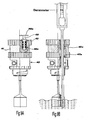
- Fig. 1 shows a pair of prior-art accumulator elements, one of which in an exploded view.
- each element is defined by a box container 1, generally consisting of clear plastic material whereon the MIN and MAX level is indicated, through screen-printing, within which the electrolyte must remain.
- Box body 1 is closed above by a coloured plastics lid 2.
- the negative plate assembly is indicated and by 4 the assembly of positive plates made of small pipes.
- a microporous separator 5 is arranged, while a plastic spray-shield 6 and a pole-covering dome-shaped cap 8 are housed above.
- an electrical connection 9 is provided, capable of mutually connecting in series the various elements, coated with self-extinguishing material.
- an electrolyte topping-up hole is provided, within which a venting plug 10 compliant with standard DIN40740 is housed, for example model 242TSG manufactured by T.a.b.a. S.r.l.
- Fig. 2 shows a battery of stationary elements, each of 2V, connected in series to provide an overall voltage of 48V. It consists of 24 elements arranged on two parallel rows.
- connection between the various adjacent elements are established through electric bridges 13 which end, on the two head elements, with two terminal clamps connected to respective outlet cables 14.
- Such cables are intended to be connected to the current rectifier and in parallel to the electric system whereto electric continuity is guaranteed.
- venting plugs 10 are housed, which are described in detail in the following.
- Figs. 3 and 4 show two types of bayonet-type venting plugs with known-type ceramic filter, typically employed on stationary battery elements.
- Fig. 3 shows a DIN-compliant plug provided with a cylindrical filter 21 hot pressure welded between an upper plastic lid 22 and a lower base 23 with which a lower crown is integral, provided with a double-bayonet configuration 24.
- the lid portion 22 houses inside a tubular structure 25, with a funnel mouth 26, for the introduction of distilled water into the accumulator element.
- annular rubber gasket 27 is provided, intended to accomplish a seal against the lid 2 of element 1 when the plug is tightened within the respective opening by the engagement with bayonet system 24.
- Fig. 4 shows another plug with closed dome-shaped ceramic filter 31, wherefrom it takes the name of "dome-shaped plug".
- Ceramic filter 31 is hot pressure welded on a single plug body 33, itself having a double-bayonet configuration 34 and an annular rubber gasket 37.
- the dome-shaped plug provides for plug body 33 to be preferably provided with a locking ring 38, by which it is possible to grip the plug firmly into one's hand to screw it open and closed easily, so as to free the housing seat and accomplish battery top up.
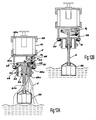
- Fig. 5 shows that the plug with ceramic cylindrical filter 21 has a topping-up pipe 25 which drops to below the minimum level of the electrolyte: through funnel portion 26, topping up can hence be easily performed by simply pouring distilled water from above. Since pipe 25 remains below the electrolyte level, the gases (in particular hydrogen) released during operation are nevertheless forced to pass through ceramic filter 21.
- the dome-shaped plug there is no free access to the upper part: it is hence necessary to unscrew the plug, acting on locking ring 38, and remove the plug from the element to perform the topping up of the electrolyte ( fig. 6 ).
- topping up is hence an awkward and time-consuming operation (particularly with the dome-shaped plug).
- the object of the present invention is hence that of offering a plug with blast-resistant filter, for stationary batteries, which is simple and inexpensive, especially in the assembly thereof and in the mounting thereof on the battery, and which allows to reduce maintenance operations for electrolyte topping up.
- a plug with cylindrical filter according to the invention is shown in figs. 8-12 .
- the plug comprises a substantially hollow plug body 40, generally made of plastic material, which acts also as a base for filter element 41.
- Ceramic filter 41 is in the shape of a cylindrical wall which may be made, for example, of two different materials: silicon carbide or corundum, with different granulometric characteristics depending on use requirements.
- the height of filter 41 may vary, thus determining the area of the porous surface and hence the flow rate of the gases it is capable of disposing.
- Cylindrical filter 41 is welded between a cap 42 and a lower flange 43 belonging to plug body 40, both made of plastic material. The welding process occurs under heat and under pressure.
- cap 42 and flange 43 are advantageously provided with three welding directrices 42a and 43a ( figs. 12A and 12B ) in the form of concentric, circumferential (triangular-section) ridges.
- the three circumferential ridges have a diameter ranging between the outer diameter and the inner diameter of ceramic filter 41, and are manufactured by integral moulding with cap 42 and with flange 43.
- Cap 42 and flange 43 have a striped or knurled outer surface which makes the handling of the entire plug more effective.
- topping up bowl V is obtained, connected to the outside through two orientable connections 44a and 44b.
- a transfer conduit V 1 departs, which puts in communication bowl V with the underlying cavity of body 40, which further has a delivery opening 40a for the inward flow of the battery element.
- conduit V 1 rises by a short measure from the bottom of bowl V, so that a permanent level of the topping up liquid inside bowl V is established.
- Conduit V 1 ends below with an outlet nozzle V 2 intended to be closed by a rubber plug 50 mounted movable on a float system.
- rubber 50 is integral with an articulated rod 51 which is constrained in rotation about a hinge 52, or simply a wedge abutment, integral with the wall of body 40.
- articulated rod 51 is connected to a fork lever 53 through a shaft/hole coupling 54.
- Fork lever 53 is L-shaped, as visible in figs. 12A and 12B , and is guided in a vertical translation motion by a gasket ring 54 mounted at the bottom of a lower sleeve 55 of body 40.
- a small rod 53a is provided, which is made integral with a float 56, intended to float on the electrolyte liquid inside the accumulator element.
- articulated rod 51 receives an upward thrust by lever 53 - in turn pushed upwards by float 56 - which forces it to rotate around hinge or wedge 52. In this rotation movement, articulated rod 51 pushes rubber 50 to close nozzle V 2 , so as to prevent the entry of the topping up liquid contained in bowl V 1 .
- the relative size of the components and the mounting position of the plug on the accumulator element are such that, when the electrolyte liquid level is above the minimum desired level, the thrust on the float maintains nozzle V 2 closed ( fig. 12B ).
- float 56 drops and, consequently, rubber 50 moves away from nozzle V 2 , opening the outlet of topping-up liquid F (typically distilled water) from bowl V ( Fig. 12A ).
- the lever arm is thus defined to exploit as much as possible the useful room in the plug, transferring onto the closing point of nozzle V 2 a force equal to about 7 times the Archimedean thrust supplied by the electrolyte liquid onto the float.
- the plug with cylindrical filter according to the invention is arranged for the introduction of a probe (densimeter, thermometer, or other) to be able for checking the physical conditions of the electrolyte without having to disassemble the plug from its seat.
- upper cap 42 is provided with a vertical channel 42a ( fig. 9B ), which runs within cylindrical filter 41 and is aligned with a hole 43a and with an opening in the lower part of body 40 which opens towards the inside of the accumulator element.
- conduit 42a is intended to be closed by a closing pin 48, provided with one or more circumferential gaskets and pressure-coupled within conduit 42a.
- conduit 42 is arranged at a shorter radial distance from the symmetry axis than the diameter of float 56; said float, however, has a side recess suitable to let the probe pass through, which probe is introduced into the accumulator element.
- plug body 40 is introduced snapwise into a lower cup coupled with the accumulator seat.
- the lower part of body 40 is shaped as a flexible cylindrical wall 49, for example provided with longitudinal notches 49b.
- annular bevelled relief 49a is provided, which ensures that body 40 cannot disengage from the lower cup once snap-coupled therewith.
- the lower cup has a cylindrical wall 46 whereon bayonet-type reliefs for the double-bayonet engagement with the corresponding opening/seat of the accumulator are formed.
- the cup has a preferably notched locking ring 45, beneath which an annular gasket 47 is arranged, intended to seal against the edge of the accumulator seat.
- a toroidal gasket O such as an O-ring, is preferably arranged, which ensures a more stable coupling between these two parts.
- Figs. 14A-14C and 15 show various views of the cup according to the invention.
- connection 42a and 42b for water inflow and outflow, thereby guaranteeing the free orientation thereof.
- the opportunity to freely orientate the two connections 42a and 42b is important for the connection of the various plugs of a battery, as will be shown below.
- a second advantageous result is that of maintaining the plug unconstrained in rotation from the cup. This is useful during the final assembly phase, as will be shown further on.
- Fig. 13 shows instead a dome-shaped cap according to the invention. All the components are identical to the ones described above, except for the upper part of the plug.
- flange 43 of body 40 only a dome-shaped filter 41', known per se, is applied.
- the connection of filter 41' to flange 43 may be obtained by the method indicated above, here too exploiting three cylindrical cusp-shaped directrices to promote welding.
- Fig. 16 shows the way of introduction of a plug according to the invention into the seat of an accumulator element.
- the plug Once the plug has been introduced into the suitable housing, it is provided to fully tighten the double-bayonet cup part, acting on locking ring 45. Due to the notches obtained on locking ring 45, it is possible to perform the tightening with the help of a suitable key ( fig. 18A ), also of plastic material, such as the one shown in fig. 17 .
- the tightening occurs by screwing locking ring 45 in a clockwise direction, until adequate compression of gasket 47 on the mouth of the housing seat is accomplished, so as to guarantee a good seal.
- the plug is securely fastened to the battery element, but the upper part - due to the snap coupling with the cup part - maintains the ability to rotate with respect to the accumulator seat: it can therefore be acted upon to orient the plug manually ( Fig. 18B ) and to arrange connections 44a and 44b on the side providing easiest access for the subsequent connection operation.
- the communicating vessels are indeed the accumulator elements.
- Circuit pressure is determined by the piezometric height of a storage tank S of the topping up liquid (distilled water) whereto the system is connected.
- tank S may be positioned in a desired, easily accessible location.
- a filter plug has been provided, either cylindrical or dome-shaped, which does not require awkward or time-consuming operations to perform the topping up, but which simply requires to keep the piezometric level of an easily-accessible single tank up-to-date.
Landscapes
- Chemical & Material Sciences (AREA)
- Chemical Kinetics & Catalysis (AREA)
- Electrochemistry (AREA)
- General Chemical & Material Sciences (AREA)
- Filling, Topping-Up Batteries (AREA)
- Gas Exhaust Devices For Batteries (AREA)
Abstract
Description
- The present invention refers to a venting plug for batteries, in particular to a plug with anti-blasting protection.
- As known, the batteries of stationary accumulators are fixed installations of electric batteries consisting of lead members immersed in an electrolytic solution. They are intended to supply, for example in case of emergency (typically discontinuation of the mains supply), electric appliances which need a uninterrupted power supply without variations or drops. They are normally employed in auxiliary services of power plant units and substations, in telephone and telegraph exchanges, in emergency light plants for public facilities, in emergency power plants for cableways and freight elevators, for continuous-cycle processes, to supply electronic computers or further to store electric power coming from photovoltaic systems (solar batteries).
- A stationary battery of lead accumulators is connected in parallel to the electric mains it supports and consists of electrochemical elements, each having a conventional voltage (typically of about 2V). The number of elements, connected in series, determines the battery voltage value.
- Each element may be built with planar or tubular plates. In the first case the plates consist of alloyed lead-antimony grids, with glass-fibre separators supporting the positive active matter and microporous polyethylene diaphragms. In the second case the positive plates are frames made of small pipes, consisting of sheaths containing active matter and permeable to electrolyte; the power is extracted through lead-alloy rheophores inside the tubular electrodes; in this case too the diaphragms between the plates are made of microporous polyethylene.
- The electrolyte wherein the plates are immersed consists of a solution of sulphuric acid (density equal to 1.21 - 1.25 dm3 of electrolyte/dm3 of water).
- In these accumulators, the free acid fills up to a preset level the hollow body of the element, consisting of a box container, normally made of clear SAN, closed above by a sealed cover and by a screwed-on or pushed-in, or bayonet-style fastened plug. The function of these plugs is also that of allowing the regular outflow of the hydrogen and oxygen released by the electrochemical process within the element.
- The battery moreover is also electrically connected on one side to the circuit of the appliance (i.e. to the appliance requiring continuous power supply) and, on the other side, to a power rectifier (device capable of converting alternate current from the mains to continuous current suited to the accumulator characteristics).
- If it is connected permanently to the circuit and to the rectifier, the battery is typically kept in buffer, in case it is connected alternately to the user and to the rectifier, the battery is in charging/discharging mode.
- In any case, during the charging cycles, the electrolyte overheats and evaporates, releasing hydrogen and oxygen and causing a drop in the level of electrolyte solution.
- Therefore, as known, the two-fold need exists to periodically top up the electrolyte level, as well as to manage the release of gases, preventing them from saturating the environment and causing detonation (hydrogen, in particular, is a highly explosive gas).
- For such purpose, various plug configurations have already been suggested, which meet this two-fold need.
-
Fig. 1 shows a pair of prior-art accumulator elements, one of which in an exploded view. As clearly shown, each element is defined by a box container 1, generally consisting of clear plastic material whereon the MIN and MAX level is indicated, through screen-printing, within which the electrolyte must remain. Box body 1 is closed above by acoloured plastics lid 2. Byreference 3 the negative plate assembly is indicated and by 4 the assembly of positive plates made of small pipes. Between the two assemblies amicroporous separator 5 is arranged, while a plastic spray-shield 6 and a pole-covering dome-shaped cap 8 are housed above. Outside the lid, on each pole of the two assemblies of positive and negative plates, anelectrical connection 9 is provided, capable of mutually connecting in series the various elements, coated with self-extinguishing material. Finally, in the middle oflid 2, an electrolyte topping-up hole is provided, within which aventing plug 10 compliant with standard DIN40740 is housed, for example model 242TSG manufactured by T.a.b.a. S.r.l. -
Fig. 2 shows a battery of stationary elements, each of 2V, connected in series to provide an overall voltage of 48V. It consists of 24 elements arranged on two parallel rows. - The connections between the various adjacent elements are established through
electric bridges 13 which end, on the two head elements, with two terminal clamps connected torespective outlet cables 14. Such cables are intended to be connected to the current rectifier and in parallel to the electric system whereto electric continuity is guaranteed. - In the respective seats,
venting plugs 10 are housed, which are described in detail in the following. -
Figs. 3 and 4 show two types of bayonet-type venting plugs with known-type ceramic filter, typically employed on stationary battery elements. -
Fig. 3 shows a DIN-compliant plug provided with acylindrical filter 21 hot pressure welded between an upperplastic lid 22 and alower base 23 with which a lower crown is integral, provided with a double-bayonet configuration 24. Thelid portion 22 houses inside atubular structure 25, with afunnel mouth 26, for the introduction of distilled water into the accumulator element. In the part belowbase 23, anannular rubber gasket 27 is provided, intended to accomplish a seal against thelid 2 of element 1 when the plug is tightened within the respective opening by the engagement withbayonet system 24. -
Fig. 4 shows another plug with closed dome-shapedceramic filter 31, wherefrom it takes the name of "dome-shaped plug".Ceramic filter 31 is hot pressure welded on asingle plug body 33, itself having a double-bayonet configuration 34 and anannular rubber gasket 37. - Unlike the previous one, the dome-shaped plug provides for
plug body 33 to be preferably provided with alocking ring 38, by which it is possible to grip the plug firmly into one's hand to screw it open and closed easily, so as to free the housing seat and accomplish battery top up. - As a matter of fact, the topping up of the battery elements, according to the prior art, is effected as shown in
figs. 5 and 6. Fig. 5 shows that the plug with ceramiccylindrical filter 21 has a topping-uppipe 25 which drops to below the minimum level of the electrolyte: throughfunnel portion 26, topping up can hence be easily performed by simply pouring distilled water from above. Sincepipe 25 remains below the electrolyte level, the gases (in particular hydrogen) released during operation are nevertheless forced to pass throughceramic filter 21. Viceversa, with the dome-shaped plug, there is no free access to the upper part: it is hence necessary to unscrew the plug, acting onlocking ring 38, and remove the plug from the element to perform the topping up of the electrolyte (fig. 6 ). - As can be guessed, topping up is hence an awkward and time-consuming operation (particularly with the dome-shaped plug).
- The object of the present invention is hence that of offering a plug with blast-resistant filter, for stationary batteries, which is simple and inexpensive, especially in the assembly thereof and in the mounting thereof on the battery, and which allows to reduce maintenance operations for electrolyte topping up.
- Such object is achieved through a device as disclosed in its essential features in the attached main claim.
- Other inventive aspects of the invention are disclosed in the dependent claims.
- Further features and advantages of the device according to the invention will in any case be more evident from the following detailed description of some sample embodiments, given by way of example and shown in the accompanying drawings, wherein:
-
fig. 1 is a partly-exploded, perspective view of a pair of exemplary accumulators provided with a prior-art plug; -
fig. 2 is a perspective view of a battery of accumulators as infig. 1 ; -
figs. 3 and 4 are partly-in-section, elevation views of two prior art plugs, with a cylindrical filter and with a dome-shaped filter, respectively; -
figs. 5 and 6 are side elevation views, partly showing-through, which show the prior-art topping-up modes with the two plugs offigs. 3 and 4 ; -
fig. 7 is a perspective view of a plug with a dome-shaped filter according to the invention; -
fig. 8 is a perspective view of a plug with a cylindrical filter according to the invention; -
figs. 9A and 9B are front elevation views, partly in section, of the plug offig. 8 in two different operational states; -
figs. 10, 10A, 11 and 11A are side elevation, top plan, front elevation and bottom plan views, respectively, of the plug offig. 8 ; -
figs. 12A and 12B are longitudinal-section views in two operational states of the plug offig. 8 ; -
fig. 13 is a side elevation view of a plug with a dome-shaped filter according to the invention; -
figs. 14A-14C are top plan, side elevation and bottom plan views, respectively, of a cup element according to the invention; -
fig. 15 is an exploded section view of the cup element offig. 14B with the relative seals; -
fig. 16 is an interrupted, perspective view which shows the way of housing the plug according to the invention; -
fig. 17 is a diagrammatic view of a tightening key according to the invention; -
figs. 18A and 18B are interrupted perspective views which show the tightening and then plug orientation procedure according to the invention; and -
fig. 19 is a perspective view of a battery provided with the topping up assembly according to the invention. -
Figs. 7 and 8 show altogether two plugs according to the invention, with dome-shaped filter and with cylindrical filter, respectively. - In the following detailed description it will be understood that, unless differently specified, the materials and the building techniques of the individual components are substantially correspondent to the prior-art ones illustrated above.
- A plug with cylindrical filter according to the invention is shown in
figs. 8-12 . - With reference to
fig. 10 , it is pointed out that the plug comprises a substantiallyhollow plug body 40, generally made of plastic material, which acts also as a base forfilter element 41.Ceramic filter 41 is in the shape of a cylindrical wall which may be made, for example, of two different materials: silicon carbide or corundum, with different granulometric characteristics depending on use requirements. The height offilter 41 may vary, thus determining the area of the porous surface and hence the flow rate of the gases it is capable of disposing. -
Cylindrical filter 41 is welded between acap 42 and alower flange 43 belonging to plugbody 40, both made of plastic material. The welding process occurs under heat and under pressure. - For such purpose, in the inner contact areas of
filter 41,cap 42 andflange 43 are advantageously provided with threewelding directrices figs. 12A and 12B ) in the form of concentric, circumferential (triangular-section) ridges. The three circumferential ridges have a diameter ranging between the outer diameter and the inner diameter ofceramic filter 41, and are manufactured by integral moulding withcap 42 and withflange 43. - During pressure welding of
parts filter 41 in between,directrices -
Cap 42 andflange 43 have a striped or knurled outer surface which makes the handling of the entire plug more effective. - In the central part of the plug an automatic topping up arrangement of the distilled water is obtained, which is better illustrated in the following.
- Inside
hollow body 40 a topping up bowl V is obtained, connected to the outside through twoorientable connections - From bowl V a transfer conduit V1 departs, which puts in communication bowl V with the underlying cavity of
body 40, which further has adelivery opening 40a for the inward flow of the battery element. Preferably, conduit V1 rises by a short measure from the bottom of bowl V, so that a permanent level of the topping up liquid inside bowl V is established. - Conduit V1 ends below with an outlet nozzle V2 intended to be closed by a
rubber plug 50 mounted movable on a float system. In particular,rubber 50 is integral with an articulatedrod 51 which is constrained in rotation about ahinge 52, or simply a wedge abutment, integral with the wall ofbody 40. At the opposite end, articulatedrod 51 is connected to afork lever 53 through a shaft/hole coupling 54. -
Fork lever 53 is L-shaped, as visible infigs. 12A and 12B , and is guided in a vertical translation motion by agasket ring 54 mounted at the bottom of alower sleeve 55 ofbody 40. - At the lower end of L-shaped
lever 53, asmall rod 53a is provided, which is made integral with afloat 56, intended to float on the electrolyte liquid inside the accumulator element. - During operation, articulated
rod 51 receives an upward thrust by lever 53 - in turn pushed upwards by float 56 - which forces it to rotate around hinge orwedge 52. In this rotation movement, articulatedrod 51 pushesrubber 50 to close nozzle V2, so as to prevent the entry of the topping up liquid contained in bowl V1. The relative size of the components and the mounting position of the plug on the accumulator element are such that, when the electrolyte liquid level is above the minimum desired level, the thrust on the float maintains nozzle V2 closed (fig. 12B ). Viceversa, when the electrolyte level drops below the minimum, float 56 drops and, consequently,rubber 50 moves away from nozzle V2, opening the outlet of topping-up liquid F (typically distilled water) from bowl V (Fig. 12A ). - The lever arm is thus defined to exploit as much as possible the useful room in the plug, transferring onto the closing point of nozzle V2 a force equal to about 7 times the Archimedean thrust supplied by the electrolyte liquid onto the float.
- According to a preferred variant, the plug with cylindrical filter according to the invention is arranged for the introduction of a probe (densimeter, thermometer, or other) to be able for checking the physical conditions of the electrolyte without having to disassemble the plug from its seat.
- For such purpose,
upper cap 42 is provided with avertical channel 42a (fig. 9B ), which runs withincylindrical filter 41 and is aligned with ahole 43a and with an opening in the lower part ofbody 40 which opens towards the inside of the accumulator element. - In normal operating conditions,
conduit 42a is intended to be closed by aclosing pin 48, provided with one or more circumferential gaskets and pressure-coupled withinconduit 42a. - Should one have to insert the desired probe, for example the densimeter shown in
fig. 9B , it is sufficient to removepin 48 fromconduit 42a, by acting on ahandle 48a thereof, and to introduce the rectilinear probe which may run entirely across the plug until it descends beyondfloat 56. In order to limit the radial dimensions of the plug,conduit 42 is arranged at a shorter radial distance from the symmetry axis than the diameter offloat 56; said float, however, has a side recess suitable to let the probe pass through, which probe is introduced into the accumulator element. - According to a further preferred variant, plug
body 40 is introduced snapwise into a lower cup coupled with the accumulator seat. For such purpose, the lower part ofbody 40 is shaped as a flexiblecylindrical wall 49, for example provided withlongitudinal notches 49b. At the mouth ofcylindrical wall 49 an annularbevelled relief 49a is provided, which ensures thatbody 40 cannot disengage from the lower cup once snap-coupled therewith. - Also, the lower cup has a
cylindrical wall 46 whereon bayonet-type reliefs for the double-bayonet engagement with the corresponding opening/seat of the accumulator are formed. In the upper part the cup has a preferably notched lockingring 45, beneath which anannular gasket 47 is arranged, intended to seal against the edge of the accumulator seat. - Between the cup and plug
body 40 a toroidal gasket O, such as an O-ring, is preferably arranged, which ensures a more stable coupling between these two parts. -
Figs. 14A-14C and 15 show various views of the cup according to the invention. - The snap mounting between
plug body 40 and the underlying coupling cup in the accumulator seat allows to easily enclose between themconnections 42a and 42b for water inflow and outflow, thereby guaranteeing the free orientation thereof. As a matter of fact, the opportunity to freely orientate the twoconnections 42a and 42b is important for the connection of the various plugs of a battery, as will be shown below. - A second advantageous result is that of maintaining the plug unconstrained in rotation from the cup. This is useful during the final assembly phase, as will be shown further on.
-
Fig. 13 shows instead a dome-shaped cap according to the invention. All the components are identical to the ones described above, except for the upper part of the plug. As a matter of fact, aboveflange 43 ofbody 40 only a dome-shaped filter 41', known per se, is applied. The connection of filter 41' to flange 43 may be obtained by the method indicated above, here too exploiting three cylindrical cusp-shaped directrices to promote welding. -
Fig. 16 shows the way of introduction of a plug according to the invention into the seat of an accumulator element. - Once the plug has been introduced into the suitable housing, it is provided to fully tighten the double-bayonet cup part, acting on locking
ring 45. Due to the notches obtained on lockingring 45, it is possible to perform the tightening with the help of a suitable key (fig. 18A ), also of plastic material, such as the one shown infig. 17 . The tightening occurs by screwing lockingring 45 in a clockwise direction, until adequate compression ofgasket 47 on the mouth of the housing seat is accomplished, so as to guarantee a good seal. - Thereby, the plug is securely fastened to the battery element, but the upper part - due to the snap coupling with the cup part - maintains the ability to rotate with respect to the accumulator seat: it can therefore be acted upon to orient the plug manually (
Fig. 18B ) and to arrangeconnections - All adjacent connections are put in communication by small connecting pipes T (
fig. 19 ), so as to connect in series all the topping up bowls V of the individual plugs of the various battery elements. - Thereby a system of pressurised communicating vessels is created. The communicating vessels are indeed the accumulator elements. Circuit pressure is determined by the piezometric height of a storage tank S of the topping up liquid (distilled water) whereto the system is connected.
- Evidently, tank S may be positioned in a desired, easily accessible location.
- As can be understood, therefore, with the above-described plug the objects set forth in the preliminary remarks may be achieved. As a matter of fact, a filter plug has been provided, either cylindrical or dome-shaped, which does not require awkward or time-consuming operations to perform the topping up, but which simply requires to keep the piezometric level of an easily-accessible single tank up-to-date.
- There is hence no need for continuous support for the visual monitoring of the electrolyte level in all the elements forming the electric accumulator. This determines a reduced presence of the operator and a resulting increased safety of maintenance personnel.
- Finally, the specific configuration and construction ensures a general inexpensiveness and ease of assembly.
- However, it is understood that protection of the above-described invention is not limited to the particular embodiments shown, but extends to any other equivalent construction variant as defined in the attached claims.
Claims (8)
- Venting plug for stationary batteries, of the type comprising a support body, which may be screwed into an upper opening of a battery element, provided with at least one topping-up hole intended to cause an electrolyte topping-up liquid to precipitate into the battery element which liquid is introduced into the upper part of said support body, and further comprising a porous element, mounted in the upper part of said support body, intended to act as a filtering barrier for the gases which rise up from said battery element towards the outside along said topping-up hole, characterised in that said support body has inside a topping-up bowl, communicating with two inlet and outlet connections, provided with an upwardly-protruding conduit which opens below the bowl into an outlet nozzle, and in that below the bowl there is provided a hermetic closing element of said nozzle controlled by a float assembly which leads said closing element to obstruct said nozzle when the electrolyte level lies above a preset operational level.
- Venting plug for stationary batteries as claimed in claim 1), wherein a lower cup provided with coupling means intended to cooperate with similar coupling means in the upper opening of the battery element is further provided, said cup being apt to be snap-coupled with the support body, so as to define a mutual axial constraint, but free mutual rotation.
- Venting plug for stationary batteries as claimed in claim 2), wherein said inlet and outlet connections may be oriented and are rotatably sandwiched between an upper flange portion and a lower flange portion, to be moved closer to each other during mounting, the upper one integral with the support body and the lower one integral with the lower cup.
- Venting plug for stationary batteries as claimed in claim 3), wherein said lower flange is part of a locking ring of the lower cup.
- Venting plug for stationary batteries as claimed in claim 4), wherein said locking ring is provided with a notched surface which may be coupled with a respective tightening key.
- Venting plug as claimed in any one of the preceding claims, wherein said porous element is shaped as a hollow ceramic body, hot-pressure-welded on a support portion of the plug body.
- Venting plug as claimed in claim 6), wherein said support portion of plastic material has a plurality of circumferential and concentric ridges apt to enter, in a heated condition, the ceramic material.
- Topping-up assembly for a stationary battery, comprising a plurality of plugs as claimed in any one of the preceding claims, characterised in that each plug is connected with two adjacent plugs by pipes leading to said inlet and outlet connections, respectively, the circuit comprising said plugs and relative pipes further being connected to a topping-up liquid tank apt to establish a desired piezometric height of topping-up liquid for said circuit.
Priority Applications (3)
| Application Number | Priority Date | Filing Date | Title |
|---|---|---|---|
| EP08425416A EP2133940B1 (en) | 2008-06-12 | 2008-06-12 | Venting plug for stationary batteries, with blast-resistant protection and unlimited, automatic topping-up system, and topping-up assembly employing said plug |
| AT08425416T ATE519239T1 (en) | 2008-06-12 | 2008-06-12 | VENTILATION CONNECTOR FOR STATIONARY BATTERIES WITH RADIATION RESISTANCE PROTECTION AND SYSTEM FOR UNLIMITED AUTOMATIC INSTALLATION AND INSTALLATION ASSEMBLY WITH SAID CONNECTOR |
| US12/482,744 US20090311582A1 (en) | 2008-06-12 | 2009-06-11 | Venting plug for stationary batteries, with blast-resistant protection and unlimited, automatic topping-up system, and topping-up assembly employing said plug |
Applications Claiming Priority (1)
| Application Number | Priority Date | Filing Date | Title |
|---|---|---|---|
| EP08425416A EP2133940B1 (en) | 2008-06-12 | 2008-06-12 | Venting plug for stationary batteries, with blast-resistant protection and unlimited, automatic topping-up system, and topping-up assembly employing said plug |
Publications (2)
| Publication Number | Publication Date |
|---|---|
| EP2133940A1 EP2133940A1 (en) | 2009-12-16 |
| EP2133940B1 true EP2133940B1 (en) | 2011-08-03 |
Family
ID=40551564
Family Applications (1)
| Application Number | Title | Priority Date | Filing Date |
|---|---|---|---|
| EP08425416A Not-in-force EP2133940B1 (en) | 2008-06-12 | 2008-06-12 | Venting plug for stationary batteries, with blast-resistant protection and unlimited, automatic topping-up system, and topping-up assembly employing said plug |
Country Status (3)
| Country | Link |
|---|---|
| US (1) | US20090311582A1 (en) |
| EP (1) | EP2133940B1 (en) |
| AT (1) | ATE519239T1 (en) |
Families Citing this family (3)
| Publication number | Priority date | Publication date | Assignee | Title |
|---|---|---|---|---|
| ITPD20130127A1 (en) * | 2013-05-10 | 2014-11-11 | Sovema Spa | PLANT FOR ELECTROCHEMICAL TRAINING OF ACCUMULATORS AND ADDITIONAL DEVICE OF AN ELECTROLYTIC SOLUTION TO A CELL OF AN ACCUMULATOR FOR SUCH SYSTEM |
| DE102015200571A1 (en) * | 2015-01-15 | 2016-07-21 | Siemens Aktiengesellschaft | Standard connections for CO filters on battery systems |
| CN107666020A (en) * | 2017-11-12 | 2018-02-06 | 孔祥贵 | A kind of temperature control storage pond with cooling circulation automatic fluid filling function |
Family Cites Families (5)
| Publication number | Priority date | Publication date | Assignee | Title |
|---|---|---|---|---|
| FR2311412A1 (en) * | 1975-05-14 | 1976-12-10 | Europ Accumulateurs | Accumulator battery cell automatic filling cap - has float operrated valve to give automatic filling with water when level in cell drops |
| FR2374748A1 (en) * | 1976-12-20 | 1978-07-13 | Europ Accumulateurs | Level indicating filler cap for lead-acid battery - has rod connected to float to indicate level of electrolyte in cell |
| US4517261A (en) * | 1983-07-01 | 1985-05-14 | Energy Development Associates, Inc. | Hydrogen gas relief valve |
| DE19647151A1 (en) * | 1996-11-14 | 1998-06-25 | Reinhard Landau | Water refill plug for batteries containing liquid electrolyte |
| EP1557598A3 (en) * | 2004-01-20 | 2005-12-28 | William E. M. Jones | Float valve assembly for battery |
-
2008
- 2008-06-12 EP EP08425416A patent/EP2133940B1/en not_active Not-in-force
- 2008-06-12 AT AT08425416T patent/ATE519239T1/en not_active IP Right Cessation
-
2009
- 2009-06-11 US US12/482,744 patent/US20090311582A1/en not_active Abandoned
Also Published As
| Publication number | Publication date |
|---|---|
| EP2133940A1 (en) | 2009-12-16 |
| US20090311582A1 (en) | 2009-12-17 |
| ATE519239T1 (en) | 2011-08-15 |
Similar Documents
| Publication | Publication Date | Title |
|---|---|---|
| TW419847B (en) | Gasket for miniature galvanic cells | |
| JP2005503651A (en) | Bipolar battery and biplate laminate | |
| EP2133940B1 (en) | Venting plug for stationary batteries, with blast-resistant protection and unlimited, automatic topping-up system, and topping-up assembly employing said plug | |
| CN116365129B (en) | End cover assembly, energy storage device and electric equipment | |
| US3536536A (en) | Storage battery system with electrolyte in a separate container | |
| CN1010636B (en) | Charging method and device for sealed secondary electrochemical power supply | |
| KR100735392B1 (en) | Manganese batteries | |
| CN111463400B (en) | Anti-spill lead-acid battery cover and battery | |
| CN209428189U (en) | A kind of electrolysis mould group and electrolysis cup | |
| GB2087637A (en) | Introducing Terminals Through Battery Covers | |
| US20240150915A1 (en) | Portable hydrogen electrolyzer integrated with water purifier indicating lifetime percentage of purification materials | |
| CN215451575U (en) | Rechargeable lithium battery | |
| CN215644864U (en) | A high-safety lithium-ion battery cap | |
| CN214477680U (en) | Novel combined cap of cylinder lithium cell | |
| KR970007516B1 (en) | Injection molded plug | |
| CN214957232U (en) | A battery outlet structure | |
| CN207966683U (en) | Combined transformer with pressure adjusting function | |
| CN213212293U (en) | Battery device convenient to change | |
| CN213636124U (en) | Power battery top cap and power battery | |
| CN217214829U (en) | Rotation type lithium cell block | |
| KR100563041B1 (en) | Cap assembly of secondary battery | |
| CN218498136U (en) | Carbon-coated nickel-cobalt lithium manganate battery | |
| CN211295307U (en) | Valve-controlled energy storage battery with internal pressure induction | |
| CN213878228U (en) | Battery case convenient to acidification | |
| CN223471672U (en) | Battery cover plate and battery monomer |
Legal Events
| Date | Code | Title | Description |
|---|---|---|---|
| PUAI | Public reference made under article 153(3) epc to a published international application that has entered the european phase |
Free format text: ORIGINAL CODE: 0009012 |
|
| AK | Designated contracting states |
Kind code of ref document: A1 Designated state(s): AT BE BG CH CY CZ DE DK EE ES FI FR GB GR HR HU IE IS IT LI LT LU LV MC MT NL NO PL PT RO SE SI SK TR |
|
| AX | Request for extension of the european patent |
Extension state: AL BA MK RS |
|
| 17P | Request for examination filed |
Effective date: 20100609 |
|
| 17Q | First examination report despatched |
Effective date: 20100709 |
|
| AKX | Designation fees paid |
Designated state(s): AT BE BG CH CY CZ DE DK EE ES FI FR GB GR HR HU IE IS IT LI LT LU LV MC MT NL NO PL PT RO SE SI SK TR |
|
| GRAP | Despatch of communication of intention to grant a patent |
Free format text: ORIGINAL CODE: EPIDOSNIGR1 |
|
| GRAS | Grant fee paid |
Free format text: ORIGINAL CODE: EPIDOSNIGR3 |
|
| GRAA | (expected) grant |
Free format text: ORIGINAL CODE: 0009210 |
|
| AK | Designated contracting states |
Kind code of ref document: B1 Designated state(s): AT BE BG CH CY CZ DE DK EE ES FI FR GB GR HR HU IE IS IT LI LT LU LV MC MT NL NO PL PT RO SE SI SK TR |
|
| REG | Reference to a national code |
Ref country code: GB Ref legal event code: FG4D |
|
| REG | Reference to a national code |
Ref country code: CH Ref legal event code: EP |
|
| REG | Reference to a national code |
Ref country code: IE Ref legal event code: FG4D |
|
| REG | Reference to a national code |
Ref country code: DE Ref legal event code: R096 Ref document number: 602008008606 Country of ref document: DE Effective date: 20110929 |
|
| REG | Reference to a national code |
Ref country code: NL Ref legal event code: VDEP Effective date: 20110803 |
|
| LTIE | Lt: invalidation of european patent or patent extension |
Effective date: 20110803 |
|
| PG25 | Lapsed in a contracting state [announced via postgrant information from national office to epo] |
Ref country code: NO Free format text: LAPSE BECAUSE OF FAILURE TO SUBMIT A TRANSLATION OF THE DESCRIPTION OR TO PAY THE FEE WITHIN THE PRESCRIBED TIME-LIMIT Effective date: 20111103 Ref country code: PT Free format text: LAPSE BECAUSE OF FAILURE TO SUBMIT A TRANSLATION OF THE DESCRIPTION OR TO PAY THE FEE WITHIN THE PRESCRIBED TIME-LIMIT Effective date: 20111205 Ref country code: FI Free format text: LAPSE BECAUSE OF FAILURE TO SUBMIT A TRANSLATION OF THE DESCRIPTION OR TO PAY THE FEE WITHIN THE PRESCRIBED TIME-LIMIT Effective date: 20110803 Ref country code: HR Free format text: LAPSE BECAUSE OF FAILURE TO SUBMIT A TRANSLATION OF THE DESCRIPTION OR TO PAY THE FEE WITHIN THE PRESCRIBED TIME-LIMIT Effective date: 20110803 Ref country code: LT Free format text: LAPSE BECAUSE OF FAILURE TO SUBMIT A TRANSLATION OF THE DESCRIPTION OR TO PAY THE FEE WITHIN THE PRESCRIBED TIME-LIMIT Effective date: 20110803 Ref country code: NL Free format text: LAPSE BECAUSE OF FAILURE TO SUBMIT A TRANSLATION OF THE DESCRIPTION OR TO PAY THE FEE WITHIN THE PRESCRIBED TIME-LIMIT Effective date: 20110803 Ref country code: SE Free format text: LAPSE BECAUSE OF FAILURE TO SUBMIT A TRANSLATION OF THE DESCRIPTION OR TO PAY THE FEE WITHIN THE PRESCRIBED TIME-LIMIT Effective date: 20110803 Ref country code: IS Free format text: LAPSE BECAUSE OF FAILURE TO SUBMIT A TRANSLATION OF THE DESCRIPTION OR TO PAY THE FEE WITHIN THE PRESCRIBED TIME-LIMIT Effective date: 20111203 |
|
| REG | Reference to a national code |
Ref country code: AT Ref legal event code: MK05 Ref document number: 519239 Country of ref document: AT Kind code of ref document: T Effective date: 20110803 |
|
| PG25 | Lapsed in a contracting state [announced via postgrant information from national office to epo] |
Ref country code: LV Free format text: LAPSE BECAUSE OF FAILURE TO SUBMIT A TRANSLATION OF THE DESCRIPTION OR TO PAY THE FEE WITHIN THE PRESCRIBED TIME-LIMIT Effective date: 20110803 Ref country code: AT Free format text: LAPSE BECAUSE OF FAILURE TO SUBMIT A TRANSLATION OF THE DESCRIPTION OR TO PAY THE FEE WITHIN THE PRESCRIBED TIME-LIMIT Effective date: 20110803 Ref country code: CY Free format text: LAPSE BECAUSE OF FAILURE TO SUBMIT A TRANSLATION OF THE DESCRIPTION OR TO PAY THE FEE WITHIN THE PRESCRIBED TIME-LIMIT Effective date: 20110803 Ref country code: GR Free format text: LAPSE BECAUSE OF FAILURE TO SUBMIT A TRANSLATION OF THE DESCRIPTION OR TO PAY THE FEE WITHIN THE PRESCRIBED TIME-LIMIT Effective date: 20111104 Ref country code: SI Free format text: LAPSE BECAUSE OF FAILURE TO SUBMIT A TRANSLATION OF THE DESCRIPTION OR TO PAY THE FEE WITHIN THE PRESCRIBED TIME-LIMIT Effective date: 20110803 Ref country code: PL Free format text: LAPSE BECAUSE OF FAILURE TO SUBMIT A TRANSLATION OF THE DESCRIPTION OR TO PAY THE FEE WITHIN THE PRESCRIBED TIME-LIMIT Effective date: 20110803 |
|
| PG25 | Lapsed in a contracting state [announced via postgrant information from national office to epo] |
Ref country code: BE Free format text: LAPSE BECAUSE OF FAILURE TO SUBMIT A TRANSLATION OF THE DESCRIPTION OR TO PAY THE FEE WITHIN THE PRESCRIBED TIME-LIMIT Effective date: 20110803 |
|
| PG25 | Lapsed in a contracting state [announced via postgrant information from national office to epo] |
Ref country code: SK Free format text: LAPSE BECAUSE OF FAILURE TO SUBMIT A TRANSLATION OF THE DESCRIPTION OR TO PAY THE FEE WITHIN THE PRESCRIBED TIME-LIMIT Effective date: 20110803 Ref country code: CZ Free format text: LAPSE BECAUSE OF FAILURE TO SUBMIT A TRANSLATION OF THE DESCRIPTION OR TO PAY THE FEE WITHIN THE PRESCRIBED TIME-LIMIT Effective date: 20110803 |
|
| PG25 | Lapsed in a contracting state [announced via postgrant information from national office to epo] |
Ref country code: EE Free format text: LAPSE BECAUSE OF FAILURE TO SUBMIT A TRANSLATION OF THE DESCRIPTION OR TO PAY THE FEE WITHIN THE PRESCRIBED TIME-LIMIT Effective date: 20110803 Ref country code: RO Free format text: LAPSE BECAUSE OF FAILURE TO SUBMIT A TRANSLATION OF THE DESCRIPTION OR TO PAY THE FEE WITHIN THE PRESCRIBED TIME-LIMIT Effective date: 20110803 |
|
| PLBE | No opposition filed within time limit |
Free format text: ORIGINAL CODE: 0009261 |
|
| STAA | Information on the status of an ep patent application or granted ep patent |
Free format text: STATUS: NO OPPOSITION FILED WITHIN TIME LIMIT |
|
| PG25 | Lapsed in a contracting state [announced via postgrant information from national office to epo] |
Ref country code: DK Free format text: LAPSE BECAUSE OF FAILURE TO SUBMIT A TRANSLATION OF THE DESCRIPTION OR TO PAY THE FEE WITHIN THE PRESCRIBED TIME-LIMIT Effective date: 20110803 |
|
| 26N | No opposition filed |
Effective date: 20120504 |
|
| REG | Reference to a national code |
Ref country code: DE Ref legal event code: R097 Ref document number: 602008008606 Country of ref document: DE Effective date: 20120504 |
|
| PGFP | Annual fee paid to national office [announced via postgrant information from national office to epo] |
Ref country code: IT Payment date: 20120619 Year of fee payment: 5 |
|
| PGFP | Annual fee paid to national office [announced via postgrant information from national office to epo] |
Ref country code: DE Payment date: 20120802 Year of fee payment: 5 Ref country code: FR Payment date: 20120711 Year of fee payment: 5 |
|
| PG25 | Lapsed in a contracting state [announced via postgrant information from national office to epo] |
Ref country code: MC Free format text: LAPSE BECAUSE OF NON-PAYMENT OF DUE FEES Effective date: 20120630 |
|
| REG | Reference to a national code |
Ref country code: CH Ref legal event code: PL |
|
| REG | Reference to a national code |
Ref country code: CH Ref legal event code: PL |
|
| GBPC | Gb: european patent ceased through non-payment of renewal fee |
Effective date: 20120612 |
|
| REG | Reference to a national code |
Ref country code: IE Ref legal event code: MM4A |
|
| PG25 | Lapsed in a contracting state [announced via postgrant information from national office to epo] |
Ref country code: LI Free format text: LAPSE BECAUSE OF NON-PAYMENT OF DUE FEES Effective date: 20120630 Ref country code: GB Free format text: LAPSE BECAUSE OF NON-PAYMENT OF DUE FEES Effective date: 20120612 Ref country code: IE Free format text: LAPSE BECAUSE OF NON-PAYMENT OF DUE FEES Effective date: 20120612 Ref country code: CH Free format text: LAPSE BECAUSE OF NON-PAYMENT OF DUE FEES Effective date: 20120630 |
|
| PG25 | Lapsed in a contracting state [announced via postgrant information from national office to epo] |
Ref country code: BG Free format text: LAPSE BECAUSE OF FAILURE TO SUBMIT A TRANSLATION OF THE DESCRIPTION OR TO PAY THE FEE WITHIN THE PRESCRIBED TIME-LIMIT Effective date: 20111103 |
|
| PG25 | Lapsed in a contracting state [announced via postgrant information from national office to epo] |
Ref country code: MT Free format text: LAPSE BECAUSE OF FAILURE TO SUBMIT A TRANSLATION OF THE DESCRIPTION OR TO PAY THE FEE WITHIN THE PRESCRIBED TIME-LIMIT Effective date: 20110803 |
|
| PG25 | Lapsed in a contracting state [announced via postgrant information from national office to epo] |
Ref country code: ES Free format text: LAPSE BECAUSE OF FAILURE TO SUBMIT A TRANSLATION OF THE DESCRIPTION OR TO PAY THE FEE WITHIN THE PRESCRIBED TIME-LIMIT Effective date: 20111114 |
|
| REG | Reference to a national code |
Ref country code: DE Ref legal event code: R119 Ref document number: 602008008606 Country of ref document: DE Effective date: 20140101 |
|
| REG | Reference to a national code |
Ref country code: FR Ref legal event code: ST Effective date: 20140228 |
|
| PG25 | Lapsed in a contracting state [announced via postgrant information from national office to epo] |
Ref country code: DE Free format text: LAPSE BECAUSE OF NON-PAYMENT OF DUE FEES Effective date: 20140101 Ref country code: TR Free format text: LAPSE BECAUSE OF FAILURE TO SUBMIT A TRANSLATION OF THE DESCRIPTION OR TO PAY THE FEE WITHIN THE PRESCRIBED TIME-LIMIT Effective date: 20110803 |
|
| PG25 | Lapsed in a contracting state [announced via postgrant information from national office to epo] |
Ref country code: LU Free format text: LAPSE BECAUSE OF NON-PAYMENT OF DUE FEES Effective date: 20120612 Ref country code: IT Free format text: LAPSE BECAUSE OF NON-PAYMENT OF DUE FEES Effective date: 20130612 Ref country code: FR Free format text: LAPSE BECAUSE OF NON-PAYMENT OF DUE FEES Effective date: 20130701 |
|
| PG25 | Lapsed in a contracting state [announced via postgrant information from national office to epo] |
Ref country code: HU Free format text: LAPSE BECAUSE OF FAILURE TO SUBMIT A TRANSLATION OF THE DESCRIPTION OR TO PAY THE FEE WITHIN THE PRESCRIBED TIME-LIMIT Effective date: 20080612 |