EP2133700A1 - Sensor device & helmet incorporating same - Google Patents
Sensor device & helmet incorporating same Download PDFInfo
- Publication number
- EP2133700A1 EP2133700A1 EP09251550A EP09251550A EP2133700A1 EP 2133700 A1 EP2133700 A1 EP 2133700A1 EP 09251550 A EP09251550 A EP 09251550A EP 09251550 A EP09251550 A EP 09251550A EP 2133700 A1 EP2133700 A1 EP 2133700A1
- Authority
- EP
- European Patent Office
- Prior art keywords
- support
- retainer
- helmet
- weight
- sensor
- Prior art date
- Legal status (The legal status is an assumption and is not a legal conclusion. Google has not performed a legal analysis and makes no representation as to the accuracy of the status listed.)
- Withdrawn
Links
- 230000001133 acceleration Effects 0.000 claims abstract description 9
- 230000006835 compression Effects 0.000 description 4
- 238000007906 compression Methods 0.000 description 4
- 239000000463 material Substances 0.000 description 3
- 230000035939 shock Effects 0.000 description 3
- 208000027418 Wounds and injury Diseases 0.000 description 2
- 230000001351 cycling effect Effects 0.000 description 2
- 230000006378 damage Effects 0.000 description 2
- 208000014674 injury Diseases 0.000 description 2
- 230000004075 alteration Effects 0.000 description 1
- 239000004744 fabric Substances 0.000 description 1
- 230000004048 modification Effects 0.000 description 1
- 238000012986 modification Methods 0.000 description 1
- 238000000465 moulding Methods 0.000 description 1
- 229920003023 plastic Polymers 0.000 description 1
- 239000004033 plastic Substances 0.000 description 1
- 230000000717 retained effect Effects 0.000 description 1
- 239000011359 shock absorbing material Substances 0.000 description 1
- 230000002459 sustained effect Effects 0.000 description 1
- 238000011179 visual inspection Methods 0.000 description 1
Images
Classifications
-
- G—PHYSICS
- G01—MEASURING; TESTING
- G01P—MEASURING LINEAR OR ANGULAR SPEED, ACCELERATION, DECELERATION, OR SHOCK; INDICATING PRESENCE, ABSENCE, OR DIRECTION, OF MOVEMENT
- G01P15/00—Measuring acceleration; Measuring deceleration; Measuring shock, i.e. sudden change of acceleration
- G01P15/02—Measuring acceleration; Measuring deceleration; Measuring shock, i.e. sudden change of acceleration by making use of inertia forces using solid seismic masses
- G01P15/03—Measuring acceleration; Measuring deceleration; Measuring shock, i.e. sudden change of acceleration by making use of inertia forces using solid seismic masses by using non-electrical means
- G01P15/032—Measuring acceleration; Measuring deceleration; Measuring shock, i.e. sudden change of acceleration by making use of inertia forces using solid seismic masses by using non-electrical means by measuring the displacement of a movable inertial mass
- G01P15/036—Measuring acceleration; Measuring deceleration; Measuring shock, i.e. sudden change of acceleration by making use of inertia forces using solid seismic masses by using non-electrical means by measuring the displacement of a movable inertial mass for indicating predetermined acceleration values
-
- A—HUMAN NECESSITIES
- A42—HEADWEAR
- A42B—HATS; HEAD COVERINGS
- A42B3/00—Helmets; Helmet covers ; Other protective head coverings
- A42B3/04—Parts, details or accessories of helmets
- A42B3/0406—Accessories for helmets
-
- A—HUMAN NECESSITIES
- A42—HEADWEAR
- A42B—HATS; HEAD COVERINGS
- A42B3/00—Helmets; Helmet covers ; Other protective head coverings
- A42B3/04—Parts, details or accessories of helmets
- A42B3/0406—Accessories for helmets
- A42B3/0433—Detecting, signalling or lighting devices
- A42B3/046—Means for detecting hazards or accidents
-
- A—HUMAN NECESSITIES
- A42—HEADWEAR
- A42B—HATS; HEAD COVERINGS
- A42B3/00—Helmets; Helmet covers ; Other protective head coverings
- A42B3/04—Parts, details or accessories of helmets
- A42B3/06—Impact-absorbing shells, e.g. of crash helmets
- A42B3/067—Impact-absorbing shells, e.g. of crash helmets with damage indication means
-
- G—PHYSICS
- G01—MEASURING; TESTING
- G01P—MEASURING LINEAR OR ANGULAR SPEED, ACCELERATION, DECELERATION, OR SHOCK; INDICATING PRESENCE, ABSENCE, OR DIRECTION, OF MOVEMENT
- G01P1/00—Details of instruments
- G01P1/07—Indicating devices, e.g. for remote indication
-
- G—PHYSICS
- G01—MEASURING; TESTING
- G01P—MEASURING LINEAR OR ANGULAR SPEED, ACCELERATION, DECELERATION, OR SHOCK; INDICATING PRESENCE, ABSENCE, OR DIRECTION, OF MOVEMENT
- G01P15/00—Measuring acceleration; Measuring deceleration; Measuring shock, i.e. sudden change of acceleration
- G01P15/18—Measuring acceleration; Measuring deceleration; Measuring shock, i.e. sudden change of acceleration in two or more dimensions
Definitions
- This invention relates to a sensor device and to a helmet incorporating such a device.
- Safety helmets for example as worn when horse riding, cycling, skiing, riding a motorcycle, or the like, are in common usage and typically comprise an outer skin and an inner, compressible layer or series of compressible components.
- the wearer of the helmet is involved in an incident which would otherwise result in an impact to the wearers head, at least part of the impact force is absorbed by compression of at least part of the compressible layer or one or more of the compressible components.
- the material of the compressible layer or compressible components is usually of non-resilient form, with the result that the compression thereof is permanent.
- the permanent compression means that the helmet will be less able to absorb a future impact, and thus may no longer be suitable for use.
- an impact sensor comprising a support, a first inertial weight, and a first retainer holding the weight against movement relative to the support, the retainer being movable relative to the support to permit release the weight for movement relative to the support in the event that the support is subject to an acceleration/deceleration of magnitude greater than a predetermined level.
- the weight once released from the retainer, is unable to return to a position in which the retainer holds the weight against movement relative the support.
- the support further includes an additional retainer and additional inertial weight arranged to be sensitive to accelerations/decelerations in a direction different to, preferably perpendicular to, that of the first retainer and first weight.
- the retainer preferably comprises a resiliently deflectable arm.
- the arm may be formed integrally with the support.
- the support may be located within, or form at least part of a casing of the sensor.
- the invention further relates to a helmet incorporating a sensor of the type defined hereinbefore.
- the helmet incorporates a plurality of such sensors, the sensors preferably being arranged to be sensitive to impacts in different directions.
- sensors are provided to permit sensing of impacts in the front-rear direction, sideways direction and vertical direction of the helmet, in use.
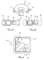
- the helmet 10 intended for use by an individual whilst skiing, horse riding, cycling, motorcycling or the like.
- the helmet 10 comprises a layer 12 of a compressible, shock absorbing material.
- a number of materials are suitable for use in the layer 12 as would be understood by a man skilled in the art and so further description thereof is not included herein.
- the layer 12 is a continuous layer, it will be understood that it could take the form of a plurality of individual, discrete components.
- the layer 12 is of generally hollow hemispherical shape, and the interior thereof is conveniently provided with fittings (not shown) to allow the helmet 10 to be positioned over and around a portion of a users head, the fittings ensuring that the helmet 10 is firmly secured in position, in use.
- the skin 14 may take a range of forms. For example, it may comprise a simple fabric cover. Alternatively, it may comprise, for example, a plastics material molding secured over the layer 12 and providing a degree of protection thereto.
- Helmets 10 of this general type are well known and are in widespread use. In use, in the event that the user in involved in an incident that would otherwise result in the user sustaining an impact to the head, the impact is sustained to the helmet 10 and the layer 12 compresses, absorbing at least part of the impact load, thus reducing the risk of injury, or reducing the extent of injury, to the user.
- each sensor 16 is sensitive to impacts in two perpendicular directions, and the orientation of the sensors 16 is preferably such that, together, the sensors 16 are sensitive to impacts in any direction, ie together the sensors 16 form a tri-axial impact sensor.
- the arrows 18 in Figure 1 illustrate the directions in which each of the sensors 16 are sensitive to impacts.
- each sensor 16 comprises a multi-part casing made up of casing components 20, 22, 24 which can be secured to one another to form a hollow casing of generally square cross section.
- a support 26 of generally square cross section.
- the dimensions of the support 26 are such that it is an interference fit within the case, thus little if any relative movement therebetween occurs, in use.
- a locating projection 28 is formed on the casing part 22 and arranged to be received within a corresponding recess 30 formed in the support 26 to ensure correct location of the support 26 within the casing, in use.
- the support 26 includes a first resilient retainer in the form of an inwardly extending arm 32 formed integrally with the support 26.
- a similar arm 34 forms a second resilient retainer.
- Each arm 32, 34 includes, at its free end, an abutment 36 formed with a recess, the recess facing an adjacent, recessed part of the support 26.
- Inertial weights 38, 40 in the form of ball bearings are held between the abutments 36 and adjacent parts of the support 26, the weights 38, 40 being received, partially, within the corresponding recesses.
- the weights 38, 40 will experience forces urging them to move relative to the support 26. If the applied force has a component of the forces acting in direction 42 illustrated in Figure 3 which is larger than a predetermined magnitude, the force will be sufficient to cause the weight 38 to ride out of the associated recesses, forcing the arm 32 to deflect inwardly, until a point is reached beyond which the weight 38 is able to move freely within the casing. Likewise, if the applied force has a component acting in the direction 44 greater than a predetermined magnitude, the weight 40 will be released for movement.
- the senor 16 will rattle, if shaken, as the respective weights 38, 40 are free to move within the casing, no longer being retained against movement by the arms 32, 34, providing an audible warning that the helmet 10 has been subject to a relatively large impact, and so may no longer be suitable for use.
- a user before putting on the helmet, simply needs to shake the helmet to determine whether or not one or more of the sensors rattles. If a rattling sound is heard, this provides an indication that the helmet may have been subject to a shock sufficient to impair the shock absorbing capability thereof.
- the user can then either decide to use an alternative helmet, or more carefully inspect the helmet in order to determine whether or not it is still suitable for use. In either case, as the risk of continued use of a helmet which no longer affords the required degree of protection is provided, it will be appreciated that safety is enhanced.
- each sensor 16 is sensitive to impacts in two perpendicular directions, it will be appreciated that this need not always be the case.
- the sensor may only be sensitive in one direction, or in more than two directions. Further, the said directions need not be perpendicular to one another.
Abstract
An impact sensor comprises a support 26, a first inertial weight 38, and a first retainer 32 holding the weight 38 against movement relative to the support 26, the retainer 32 being movable relative to the support 26 to permit release the weight 38 for movement relative to the support 26 in the event that the support 26 is subject to an acceleration/deceleration of magnitude greater than a predetermined level.

Description
- This invention relates to a sensor device and to a helmet incorporating such a device.
- Safety helmets, for example as worn when horse riding, cycling, skiing, riding a motorcycle, or the like, are in common usage and typically comprise an outer skin and an inner, compressible layer or series of compressible components. In use, if the wearer of the helmet is involved in an incident which would otherwise result in an impact to the wearers head, at least part of the impact force is absorbed by compression of at least part of the compressible layer or one or more of the compressible components. The material of the compressible layer or compressible components is usually of non-resilient form, with the result that the compression thereof is permanent. The permanent compression means that the helmet will be less able to absorb a future impact, and thus may no longer be suitable for use.
- Often the outer skin is not significantly damaged by such incidents, and it is not easy to tell simply by visual inspection whether or not a helmet has been involved in an incident sufficient to reduce the shock absorbing capability thereof. There is therefore a risk of individuals continuing to use helmets which are no longer capable of providing the required degree of protection. Where a helmet is only ever used by a single individual, then the individual has some idea of the number of impacts the helmet has been subject to. However, the individual may still be unable to gauge the magnitude of severity of the impacts, and so may not be able to accurately judge whether or not the helmet is still capable of providing protection. Where helmets are used by a number of different individuals, then the ability of a user to determine whether or not a helmet is capable of providing the required degree of protection is severely reduced.
- It is an object of the invention to provide a sensor suitable for use with a helmet to provide an indication as to whether or not a helmet has been subject to a large impact, and a helmet incorporating such a sensor.
- According to one aspect of the invention there is provided an impact sensor comprising a support, a first inertial weight, and a first retainer holding the weight against movement relative to the support, the retainer being movable relative to the support to permit release the weight for movement relative to the support in the event that the support is subject to an acceleration/deceleration of magnitude greater than a predetermined level.
- Preferably, the weight, once released from the retainer, is unable to return to a position in which the retainer holds the weight against movement relative the support.
- In such an arrangement, if the sensor is mounted upon a helmet and the helmet is involved in a large impact, rapid acceleration or deceleration of the helmet will be transmitted to the support, but the inertia of the weight will urge the weight to continue to move, deflecting or moving the retainer to release the weight, depending upon the direction of the applied acceleration or deceleration. The release of the weight will result in the sensor rattling, if shaken, providing an audible warning that the sensor and helmet have been involved in an impact.
- Preferably, the support further includes an additional retainer and additional inertial weight arranged to be sensitive to accelerations/decelerations in a direction different to, preferably perpendicular to, that of the first retainer and first weight.
- The retainer preferably comprises a resiliently deflectable arm. The arm may be formed integrally with the support. The support may be located within, or form at least part of a casing of the sensor.
- The invention further relates to a helmet incorporating a sensor of the type defined hereinbefore.
- Preferably the helmet incorporates a plurality of such sensors, the sensors preferably being arranged to be sensitive to impacts in different directions. Preferably, sensors are provided to permit sensing of impacts in the front-rear direction, sideways direction and vertical direction of the helmet, in use.
- The invention will further be described, by way of example, with reference to the accompanying drawings, in which:
-
Figure 1 is a diagrammatic view of a helmet, with part broken away, in accordance with one embodiment of the invention; -
Figures 2a and 2b are an views illustrating the components of a sensor of the helmet ofFigure 1 ; and -
Figure 3 is a view to an enlarged scale illustrating part of the sensor. - Referring to the accompanying drawings there is illustrated a
helmet 10 intended for use by an individual whilst skiing, horse riding, cycling, motorcycling or the like. Thehelmet 10 comprises alayer 12 of a compressible, shock absorbing material. A number of materials are suitable for use in thelayer 12 as would be understood by a man skilled in the art and so further description thereof is not included herein. Likewise, although in the illustrated embodiment thelayer 12 is a continuous layer, it will be understood that it could take the form of a plurality of individual, discrete components. - The
layer 12 is of generally hollow hemispherical shape, and the interior thereof is conveniently provided with fittings (not shown) to allow thehelmet 10 to be positioned over and around a portion of a users head, the fittings ensuring that thehelmet 10 is firmly secured in position, in use. - Over the
layer 12 is formed askin 14. Theskin 14 may take a range of forms. For example, it may comprise a simple fabric cover. Alternatively, it may comprise, for example, a plastics material molding secured over thelayer 12 and providing a degree of protection thereto. -
Helmets 10 of this general type are well known and are in widespread use. In use, in the event that the user in involved in an incident that would otherwise result in the user sustaining an impact to the head, the impact is sustained to thehelmet 10 and thelayer 12 compresses, absorbing at least part of the impact load, thus reducing the risk of injury, or reducing the extent of injury, to the user. - In accordance with the invention, secured to the
helmet 10 is a plurality ofsensors 16. Thesensors 16 may simply be adhered or otherwise secured to theskin 14. Alternatively, as illustrated, they may be hidden from view, being located between thelayer 12 and theskin 14. In the arrangement illustrated, foursuch sensors 16 are mounted upon thehelmet 10, thesensors 16 being spaced apart around the periphery of thehelmet 10. As described below, eachsensor 16 is sensitive to impacts in two perpendicular directions, and the orientation of thesensors 16 is preferably such that, together, thesensors 16 are sensitive to impacts in any direction, ie together thesensors 16 form a tri-axial impact sensor. Thearrows 18 inFigure 1 illustrate the directions in which each of thesensors 16 are sensitive to impacts. It will be appreciated that none of thesensors 16 are arranged to be sensitive to impacts in the upward direction in the arrangement ofFigure 1 . This is because it is very unusual for such impacts to result in permanent compression of thelayer 12. However, if it is desired to provide a sensor arrangement sensitive to impacts in this direction, this can be achieved simply by inverting one or more of thesensors 16. - Referring to
Figures 2 and 3 , eachsensor 16 comprises a multi-part casing made up ofcasing components support 26 of generally square cross section. The dimensions of thesupport 26 are such that it is an interference fit within the case, thus little if any relative movement therebetween occurs, in use. A locatingprojection 28 is formed on thecasing part 22 and arranged to be received within acorresponding recess 30 formed in thesupport 26 to ensure correct location of thesupport 26 within the casing, in use. - The
support 26 includes a first resilient retainer in the form of an inwardly extendingarm 32 formed integrally with thesupport 26. Asimilar arm 34 forms a second resilient retainer. Eacharm abutment 36 formed with a recess, the recess facing an adjacent, recessed part of thesupport 26.Inertial weights abutments 36 and adjacent parts of thesupport 26, theweights - In use, if the
sensor 16 is subject to a sudden acceleration or deceleration, theweights support 26. If the applied force has a component of the forces acting indirection 42 illustrated inFigure 3 which is larger than a predetermined magnitude, the force will be sufficient to cause theweight 38 to ride out of the associated recesses, forcing thearm 32 to deflect inwardly, until a point is reached beyond which theweight 38 is able to move freely within the casing. Likewise, if the applied force has a component acting in thedirection 44 greater than a predetermined magnitude, theweight 40 will be released for movement. In either case, thesensor 16 will rattle, if shaken, as therespective weights arms helmet 10 has been subject to a relatively large impact, and so may no longer be suitable for use. - A user, before putting on the helmet, simply needs to shake the helmet to determine whether or not one or more of the sensors rattles. If a rattling sound is heard, this provides an indication that the helmet may have been subject to a shock sufficient to impair the shock absorbing capability thereof. The user can then either decide to use an alternative helmet, or more carefully inspect the helmet in order to determine whether or not it is still suitable for use. In either case, as the risk of continued use of a helmet which no longer affords the required degree of protection is provided, it will be appreciated that safety is enhanced.
- Although in the arrangement illustrated each
sensor 16 is sensitive to impacts in two perpendicular directions, it will be appreciated that this need not always be the case. For example, the sensor may only be sensitive in one direction, or in more than two directions. Further, the said directions need not be perpendicular to one another. - A number of other modifications and alterations may be made to the arrangement described hereinbefore without departing from the scope of the invention.
Claims (12)
- An impact sensor comprising a support (26), a first inertial weight (38), and a first retainer (32) holding the weight (38) against movement relative to the support (26), the retainer (32) being movable relative to the support (26) to permit release the weight (38) for movement relative to the support (26) in the event that the support (26) is subject to an acceleration/deceleration of magnitude greater than a predetermined level.
- A sensor according to Claim 1, wherein the weight (38), once released from the retainer (32), is unable to return to a position in which the retainer (32) holds the weight (38) against movement relative the support (26).
- A sensor according to Claim 1 or Claim 2, wherein the support (26) further includes an additional retainer (34) and additional inertial weight (40) arranged to be sensitive to accelerations/decelerations in a direction different to that of the first retainer (32) and first weight (38).
- A sensor according to Claim 3 wherein the additional retainer (34) and additional inertial weight (40) are arranged to be sensitive to accelerations/decelerations in a direction perpendicular to that of the first retainer (32) and first weight (38).
- A sensor according to any of the preceding claims, wherein the retainer (32) comprises a resiliently deflectable arm.
- A sensor according to Claim 5, wherein the arm is formed integrally with the support (26).
- A sensor according to any of the preceding claims, wherein the support (26) is located within, or forms at least part of, a casing of the sensor.
- A sensor substantially as hereinbefore described with reference to the accompanying drawings.
- A helmet incorporating a sensor (16) as claimed in any of the preceding claims.
- A helmet according to Claim 9, and incorporating a plurality of such sensors (16)..
- A helmet according to Claim 10, wherein the sensors (16) are arranged to be sensitive to impacts in different directions.
- A helmet according to Claim 10 or Claim 11, wherein the sensors (16) are arranged to permit sensing of impacts in the front-rear direction, sideways direction and vertical direction of the helmet, in use.
Applications Claiming Priority (1)
| Application Number | Priority Date | Filing Date | Title |
|---|---|---|---|
| GB0810705A GB2460852A (en) | 2008-06-12 | 2008-06-12 | Impact sensor and helmet incorporating the sensor. |
Publications (1)
| Publication Number | Publication Date |
|---|---|
| EP2133700A1 true EP2133700A1 (en) | 2009-12-16 |
Family
ID=39650840
Family Applications (1)
| Application Number | Title | Priority Date | Filing Date |
|---|---|---|---|
| EP09251550A Withdrawn EP2133700A1 (en) | 2008-06-12 | 2009-06-12 | Sensor device & helmet incorporating same |
Country Status (3)
| Country | Link |
|---|---|
| US (1) | US20090307827A1 (en) |
| EP (1) | EP2133700A1 (en) |
| GB (1) | GB2460852A (en) |
Cited By (2)
| Publication number | Priority date | Publication date | Assignee | Title |
|---|---|---|---|---|
| GB2497345A (en) * | 2011-12-09 | 2013-06-12 | Ann-Marie Rutledge | Riding helmet with damage indicator |
| US9131741B2 (en) | 2012-12-12 | 2015-09-15 | Gerald Maliszewski | System and method for the detection of helmet-to-helmet contact |
Families Citing this family (19)
| Publication number | Priority date | Publication date | Assignee | Title |
|---|---|---|---|---|
| ES1071975Y (en) * | 2010-02-24 | 2010-08-02 | Luca Lancini S L | IMPACT INDICATOR DEVICE |
| US8104324B2 (en) | 2010-03-02 | 2012-01-31 | Bio-Applications, LLC | Intra-extra oral shock-sensing and indicating systems and other shock-sensing and indicating systems |
| CA2791917C (en) * | 2010-03-02 | 2019-04-09 | Bio-Applications, LLC | Intra-extra oral shock-sensing and indicating systems and other shock-sensing and indicating systems |
| EP2389822A1 (en) * | 2010-05-26 | 2011-11-30 | The Royal College of Art | Helmet |
| US9070269B2 (en) * | 2010-11-23 | 2015-06-30 | Battle Sports Science, Llc | Impact sensing device and helmet incorporating the same |
| CA2820641C (en) | 2010-11-23 | 2019-01-15 | Battle Sports Science, Llc | Impact sensing device and helmet incorporating the same |
| WO2012100053A1 (en) * | 2011-01-19 | 2012-07-26 | X2Impact, Inc. | Headgear position and impact sensor |
| US9103734B2 (en) | 2011-03-10 | 2015-08-11 | Shockwatch, Inc. | Impact indicator |
| US20130060489A1 (en) * | 2011-09-02 | 2013-03-07 | Impakt Protective Inc. | Characterization of impact experienced at a headpiece |
| US10024743B2 (en) | 2011-10-27 | 2018-07-17 | Reebok International Limited | Body mounted monitoring system and method |
| US10123582B2 (en) | 2013-06-26 | 2018-11-13 | I1 Sensortech, Inc. | Flexible impact sensor for use with a headpiece |
| US9291511B2 (en) * | 2013-09-23 | 2016-03-22 | Xerox Corporation | Shock or impact sensor |
| WO2017087719A1 (en) * | 2015-11-17 | 2017-05-26 | Eric Pedersen | A coupler for coupling a crab pot with another crab pot, and related systems and methods |
| EP3642585B1 (en) | 2017-06-23 | 2023-11-29 | Shockwatch, Inc. | Impact indicator |
| US11046454B2 (en) | 2017-08-01 | 2021-06-29 | Shockwatch, Inc. | Unmanned aerial vehicle impact monitoring system |
| WO2019083655A1 (en) | 2017-10-26 | 2019-05-02 | Shockwatch, Inc. | Impact indicator |
| WO2019152992A1 (en) * | 2018-02-05 | 2019-08-08 | VICIS, Inc. | Position-specific helmet protection |
| US11112425B2 (en) | 2019-09-30 | 2021-09-07 | Shockwatch, Inc. | Impact indicator |
| US11645489B2 (en) | 2020-05-21 | 2023-05-09 | Shockwatch, Inc. | Impact indicator |
Citations (5)
| Publication number | Priority date | Publication date | Assignee | Title |
|---|---|---|---|---|
| GB585039A (en) * | 1945-06-04 | 1947-01-29 | Clifford Hole | Stress indicators for flying machines |
| GB687373A (en) * | 1949-08-24 | 1953-02-11 | Mors Electricite | Shock-indicating device |
| US6301718B1 (en) * | 1999-11-09 | 2001-10-16 | Salomon S.A. | Protective helmet |
| WO2005058083A2 (en) * | 2003-12-12 | 2005-06-30 | Beck Gregory S | Safety helmet with shock detector, helmet attachement device with shock detector & methods |
| US20060038694A1 (en) * | 2004-08-19 | 2006-02-23 | Washington University | Electronic and microsphere-based impact detection and measurement apparatus |
Family Cites Families (4)
| Publication number | Priority date | Publication date | Assignee | Title |
|---|---|---|---|---|
| US5539935A (en) * | 1992-01-10 | 1996-07-30 | Rush, Iii; Gus A. | Sports helmet |
| JP2006053037A (en) * | 2004-08-11 | 2006-02-23 | Yutaka Shirae | Impact recording element |
| US20060162421A1 (en) * | 2005-01-21 | 2006-07-27 | Brady Worldwide, Inc. | Shock indicator |
| JP2007064711A (en) * | 2005-08-30 | 2007-03-15 | Megachips System Solutions Inc | Impact detector |
-
2008
- 2008-06-12 GB GB0810705A patent/GB2460852A/en not_active Withdrawn
-
2009
- 2009-06-11 US US12/482,591 patent/US20090307827A1/en not_active Abandoned
- 2009-06-12 EP EP09251550A patent/EP2133700A1/en not_active Withdrawn
Patent Citations (5)
| Publication number | Priority date | Publication date | Assignee | Title |
|---|---|---|---|---|
| GB585039A (en) * | 1945-06-04 | 1947-01-29 | Clifford Hole | Stress indicators for flying machines |
| GB687373A (en) * | 1949-08-24 | 1953-02-11 | Mors Electricite | Shock-indicating device |
| US6301718B1 (en) * | 1999-11-09 | 2001-10-16 | Salomon S.A. | Protective helmet |
| WO2005058083A2 (en) * | 2003-12-12 | 2005-06-30 | Beck Gregory S | Safety helmet with shock detector, helmet attachement device with shock detector & methods |
| US20060038694A1 (en) * | 2004-08-19 | 2006-02-23 | Washington University | Electronic and microsphere-based impact detection and measurement apparatus |
Cited By (2)
| Publication number | Priority date | Publication date | Assignee | Title |
|---|---|---|---|---|
| GB2497345A (en) * | 2011-12-09 | 2013-06-12 | Ann-Marie Rutledge | Riding helmet with damage indicator |
| US9131741B2 (en) | 2012-12-12 | 2015-09-15 | Gerald Maliszewski | System and method for the detection of helmet-to-helmet contact |
Also Published As
| Publication number | Publication date |
|---|---|
| GB2460852A (en) | 2009-12-16 |
| US20090307827A1 (en) | 2009-12-17 |
| GB0810705D0 (en) | 2008-07-16 |
Similar Documents
| Publication | Publication Date | Title |
|---|---|---|
| EP2133700A1 (en) | Sensor device & helmet incorporating same | |
| US9648914B2 (en) | Systems for active coupling of airbags | |
| JP6802174B2 (en) | Helmet | |
| EP2896308A1 (en) | Helmet with sliding facilitator arranged at energy absorbing layer | |
| US20200008509A1 (en) | Helmet with impact tracking | |
| US8938820B2 (en) | Protecting device for the neck | |
| US20150157080A1 (en) | Device to reduce head injury risk | |
| CN107847001A (en) | The helmet | |
| WO2019022675A1 (en) | Wearable apparatus, method and controller thereof | |
| CN107107980B (en) | Inflatable protection for child seats | |
| Bottlang et al. | Effect of helmet design on impact performance of industrial safety helmets | |
| Fukaya et al. | Protection against impact with the ground using wearable airbags | |
| JP6063110B2 (en) | Airbag device for human body | |
| US20230248104A1 (en) | Helmet rotation damping with negative torque | |
| US10729201B1 (en) | Impact protection apparatus | |
| KR101363378B1 (en) | Product for shock absorption | |
| CA2921906C (en) | Impact diffusing apparatus | |
| Capitani et al. | Design and numerical evaluation on an airbag-jacket for motorcyclists | |
| JP3106273U (en) | Two-piece shock relief safety cap | |
| WO2023213937A1 (en) | Horse-rider protection system comprising an airbag waistcoat connected to a sensor that senses falling of the horse | |
| Gilchrist et al. | Critical assessment of helmet retention system test methods | |
| US20170287610A1 (en) | Magnetic auto-repel shock helmet | |
| JP2004352113A (en) | Protecting device | |
| WO2015144662A1 (en) | Composite material, production and use thereof | |
| WO2016173797A1 (en) | Helmet |
Legal Events
| Date | Code | Title | Description |
|---|---|---|---|
| PUAI | Public reference made under article 153(3) epc to a published international application that has entered the european phase |
Free format text: ORIGINAL CODE: 0009012 |
|
| AK | Designated contracting states |
Kind code of ref document: A1 Designated state(s): AT BE BG CH CY CZ DE DK EE ES FI FR GB GR HR HU IE IS IT LI LT LU LV MC MK MT NL NO PL PT RO SE SI SK TR |
|
| STAA | Information on the status of an ep patent application or granted ep patent |
Free format text: STATUS: THE APPLICATION IS DEEMED TO BE WITHDRAWN |
|
| 18D | Application deemed to be withdrawn |
Effective date: 20100617 |