EP2133656A1 - Braking device of measuring instrument and measuring instrument - Google Patents
Braking device of measuring instrument and measuring instrument Download PDFInfo
- Publication number
- EP2133656A1 EP2133656A1 EP09162158A EP09162158A EP2133656A1 EP 2133656 A1 EP2133656 A1 EP 2133656A1 EP 09162158 A EP09162158 A EP 09162158A EP 09162158 A EP09162158 A EP 09162158A EP 2133656 A1 EP2133656 A1 EP 2133656A1
- Authority
- EP
- European Patent Office
- Prior art keywords
- spindle
- piston
- closing member
- shaft
- cylinder
- Prior art date
- Legal status (The legal status is an assumption and is not a legal conclusion. Google has not performed a legal analysis and makes no representation as to the accuracy of the status listed.)
- Granted
Links
Images



Classifications
-
- G—PHYSICS
- G01—MEASURING; TESTING
- G01B—MEASURING LENGTH, THICKNESS OR SIMILAR LINEAR DIMENSIONS; MEASURING ANGLES; MEASURING AREAS; MEASURING IRREGULARITIES OF SURFACES OR CONTOURS
- G01B3/00—Measuring instruments characterised by the use of mechanical techniques
- G01B3/002—Details
- G01B3/008—Arrangements for controlling the measuring force
-
- G—PHYSICS
- G01—MEASURING; TESTING
- G01B—MEASURING LENGTH, THICKNESS OR SIMILAR LINEAR DIMENSIONS; MEASURING ANGLES; MEASURING AREAS; MEASURING IRREGULARITIES OF SURFACES OR CONTOURS
- G01B3/00—Measuring instruments characterised by the use of mechanical techniques
- G01B3/22—Feeler-pin gauges, e.g. dial gauges
-
- Y—GENERAL TAGGING OF NEW TECHNOLOGICAL DEVELOPMENTS; GENERAL TAGGING OF CROSS-SECTIONAL TECHNOLOGIES SPANNING OVER SEVERAL SECTIONS OF THE IPC; TECHNICAL SUBJECTS COVERED BY FORMER USPC CROSS-REFERENCE ART COLLECTIONS [XRACs] AND DIGESTS
- Y10—TECHNICAL SUBJECTS COVERED BY FORMER USPC
- Y10S—TECHNICAL SUBJECTS COVERED BY FORMER USPC CROSS-REFERENCE ART COLLECTIONS [XRACs] AND DIGESTS
- Y10S33/00—Geometrical instruments
- Y10S33/06—Dial indicator shock absorber
Definitions
- the present invention relates to a braking device of a measuring instrument and the measuring instrument. More particularly, the present invention relates to a braking device of a spindle that is axially and reciprocably displaceable relative to a case body, and a measuring instrument including the braking device.
- dial gauge mechanical type, digital type
- a measuring instrument that measures a dimension or the like of an object based on a displacement of a spindle that is axially and reciprocably displaceable relative to a case body by bringing a distal end (probe) of the spindle into contact with the object.
- the distal end of the spindle is biased to project from the case body by a biasing unit. Accordingly, the spindle may vigorously collide with the object by suddenly moving down due to the biasing force.
- a braking device has been suggested in which a spindle is prevented from colliding with an object to be measured by braking a sudden movement of the spindle (for instance, see Document 1: JP-A-59-170701 ).
- a braking device 100 includes: a bush 101 for guiding a second end of a spindle 3 that penetrates a case body 2 and has a probe (not shown) on a first end; a cylinder 102 of which a first end is externally fitted to the bush 101 for accommodating the second end of the spindle 3; a piston 103 provided on the second end of the spindle 3 to define a first chamber R1 between the piston 103 and the bush 101; and a partition 104 fitted to a second end of the cylinder 102 to define a second chamber R2 between the partition 104 and the piston 103.
- the spindle 3 is biased downwardly (toward the lower side in Fig. 10 ) by a biasing unit (not shown).
- the piston 103 has an outer diameter that is slightly smaller than an inner diameter of the cylinder 102, so that a clearance having an appropriate size sufficient for a fluid to flow is provided between an outer circumference of the piston 103 and an inner circumference of the cylinder 102.
- a cap 105 is fitted to the partition 104 to define a valve chamber R3 therebetween, while a through hole 106 is provided on the partition 104 to communicate between the second chamber R2 and the valve chamber R3.
- a conical valve seat 107 is provided on the through hole 106 to accommodate a ball 108.
- An object of the invention is to provide a braking device including a lifting mechanism for a spindle and a measuring instrument including the braking device.
- a braking device of a measuring instrument which comprises a body case and a spindle that penetrates the body case to be axially and reciprocably displaceable and includes a probe at a first end, includes: a cylinder of which a first end is attached to the body case for accommodating a second end of the spindle; a piston provided on the second end of the spindle and accommodated to be reciprocably displaceable within the cylinder; a closing member provided on a second end of the cylinder to form a damper chamber between the piston and the closing member; a shaft that is opposite to the spindle by interposing the piston therebetween and penetrates the closing member; and an operating section provided on a distal end of the shaft, wherein a clearance is provided between the closing member and the shaft for circulating air between the damper chamber and an outside.
- the piston when the spindle is moved toward the first end (i.e., the side provided with the probe), the piston is also moved toward the first end in conjunction with the spindle. Accordingly, the volume of the damper chamber is expanded and the pressure of the damper chamber is reduced, thereby braking the movement of the spindle.
- the braking device can include a lifting mechanism for the spindle.
- the closing member may be displaceable in an axial direction of the shaft and contactable to a second end surface of the cylinder.
- a cap may be provided on the second end of the cylinder to cover the closing member and prevent the closing member from being displaced beyond a predetermined distance in the axial direction of the shaft.
- the cap prevents the closing member from being displaced beyond a predetermined distance in the axial direction of the shaft.
- the shaft is not significantly displaced in the axial direction of the shaft while the spindle is lifted. Consequently, when the spindle is moved toward the first end for the next measurement, for instance, the closing member can be promptly brought into contact with the second end surface of the cylinder, thereby readily exhibiting the damper effect.
- the shaft may be detachable from the piston, and a circulating hole may be provided on the piston or on both of the piston and the spindle to communicate between the damper chamber and a chamber opposite to the damper chamber by interposing the piston therebetween for circulating air.
- the braking device can be used without the lifting mechanism.
- the circulating hole is provided on the piston or on both of the piston and the spindle to communicate between the damper chamber and the chamber opposite to the damper chamber by interposing the piston therebetween for circulating the air, the pressure of the damper chamber is reduced when the spindle is moved toward the first end (i.e., the side provided with the probe).
- the movement of the spindle is braked.
- air is gradually delivered into the damper chamber through the circulating hole.
- the spindle is moved while being braked, i.e., the damper effect can be produced.
- the braking device can include the lifting mechanism.
- a measuring device includes: a body case; a spindle that penetrates the body case to be axially and reciprocably displaceable and includes a probe at a first end; a biasing unit that biases the spindle toward the first end; and the above-described braking device.
- the above-described advantages can be attained because the braking device has the same arrangements as the above-described braking device.
- the measuring instrument may be a mechanical instrument or a digital instrument.
- the digital measuring instrument may include a displacement detector that detects a displacement of the spindle and a display that displays the displacement detected by the displacement detector, in addition to the above-described arrangements.
- the displacement detector may be provided by a photoelectric type, electrostatic capacitance type or magnetic type encoder, and a gear mechanism.
- the display may be provided by a liquid crystal panel.
- a dial gauge 1 of the exemplary embodiment includes: a body case 2; a spindle 3 that penetrates the body case 2 to be axially and reciprocably displaceable; a biasing unit 4 that axially biases the spindle 3 toward a first end (the lower end in Fig. 2 ); a displacement detector 5 that detects a displacement of the spindle 3; a display 6 that displays the displacement detected by the displacement detector 5; and a braking device 7 that brakes a descending speed of the spindle 3 and includes a lifting mechanism for lifting the spindle 3 toward a second end (the upper end in Fig. 2 ).
- the body case 2 includes an accommodating space 21 therein and a stem 22 for guiding a substantially middle portion of the spindle 3 at the lower end.
- the spindle 3 includes a probe 31 having a predetermined rigidity at the lower end.
- the biasing unit 4 is provided by a coil spring 42 of which a lower end is fixed to the body case 2 and of which an upped end is fixed to a support piece 41 that is displaced in conjunction with the spindle 3.
- the displacement detector 5 includes a scale 52 fixed to the spindle 3 via an attachment 51 to be parallel to the spindle 3; and a detecting section 53 fixed to the body case 2 being spaced apart from the scale 52 by a predetermined distance for detecting a displacement of the scale 52.
- the displacement detected by the displacement detector 5 is sent to the display 6.
- the display 6 is provided by a liquid crystal panel 61 or the like arranged in a front middle portion of the body case 2.
- the braking device 7 includes: a cylinder 71 of which a lower end is fitted to the upper end of the body case 2 for communicating with the accommodating space 21 of the body case 2; a piston 72 that is provided on the upper end of the spindle 3 and is reciprocably displaceable within the cylinder 71; a cap 73 detachably screwed to the upper end of the cylinder 71; a closing member 74 placed between the cap 73 and the upper end surface of the cylinder 71; a shaft 75 connected to a side of the piston 72 opposite to the spindle 3 and extends to penetrate the center of the closing member 74 and the cap 73; and a knob 76 serving as an operating section provided on the distal end (upper end) of the shaft 75.
- An external thread 71 A is provided on the outer circumference at the upper end of the cylinder 71.
- the piston 72 is a disk, of which an outer diameter is slightly smaller than the inner diameter of the cylinder 71.
- the cap 73 prevents the closing member 74 from being displaced beyond a predetermined distance in the axial direction of the shaft 75.
- An internal thread 73A that is screwed with the external thread 71A of the cylinder 71 is provided on the inner circumference of the cap 73, and a through hole 73B is provided at the center of the cap 73.
- the closing member 74 includes a through hole 74A into which the shaft 75 is inserted.
- the closing member 74 is displaceable between the second end surface of the cylinder 71 and the cap 73 in the axial direction of the shaft 75, and forms a damper chamber 77 between the closing member 74 and the piston 72 when the closing member 74 is in contact with the upper end surface of the cylinder 71.
- a clearance 78 is provided between the through hole 74A of the closing member 74 and the shaft 75 to circulate air between the damper chamber 77 and the outside thereof.
- the closing member 74 may be made of metal or resin.
- the clearance 78 is provided to circulate air between the closing member 74 defining the damper chamber 77 and the shaft 75 connected to the piston 72, the air is gradually delivered into the damper chamber 77 through the clearance 78, thereby moving the spindle 3 while braking the movement of the spindle 3. In other words, a damper effect can be obtained.
- the knob 76 is pulled up from a state where the spindle 3 is moved down. Then, as shown in Fig. 6 , the shaft 75 is moved up, and the piston 72 and the spindle 3 that are connected with the shaft 75 are also moved up. In other words, the spindle 3 can be lifted.
- the invention is not limited to the above-described embodiment, but includes modifications and improvements as long as an object of the invention can be achieved.
- the closing member 74 is displaceable in the axial direction of the shaft 75 between the upper end surface of the cylinder 71 and the cap 73 in the exemplary embodiment, the closing member 74 is not limited thereto.
- the closing member 74 may be displaceable in the axial direction of the shaft 75 on the external side of the cap 73, i.e., between the cap 73 and the knob 76 to attain the same advantages.
- the closing member 74 may not be displaceable in the axial direction of the shaft 75.
- the closing member 74 may be fixed to the second end surface of the cylinder 71 or fixed to the external side of the cap 73.
- the shaft 75 including the knob 76 is integrated with the piston 72 to provide the lifting mechanism for lifting the spindle 3 by the shaft 75, the closing member 74 and the cap 73 in the exemplary embodiment, the mechanism of the invention is not limited thereto.
- the shaft 75 may be detachably provided on the piston 72, and a circulating hole 82 extending from the center of the piston 72 to the outer circumference of the spindle 3 may be provided so as to gradually circulate the air between the damper chamber 77 and a chamber 81 (i.e., the chamber communicating with the accommodating space 21 of the body case 2) interposing the piston 72 therebetween.
- a circulating hole 82 extending from the center of the piston 72 to the outer circumference of the spindle 3 may be provided so as to gradually circulate the air between the damper chamber 77 and a chamber 81 (i.e., the chamber communicating with the accommodating space 21 of the body case 2) interposing the piston 72 therebetween.
- a screw hole 84 may be provided on the center of the piston 72 and an external thread 85 (see Fig. 9 ) screwed with the screw hole 84 may be provided on the shaft 75.
- the circulating hole 82 may not extend from the center of the piston 72 to the outer circumference of the spindle 3.
- the circulating hole 82 may penetrate both surfaces of the piston 72.
- the braking device can include the lifting mechanism.
- the cover cap 83 is removed to provide the closing member 74 on the second end surface of the cylinder 71 while the cap 73 is screwed with the upper end of the cylinder 71 and the shaft 75 including the knob 76 at the distal end is screwed with the piston 72 as shown in Fig. 9
- the braking device 7 can include the lifting mechanism afterward.
- the lower end (the end closer to the body case 2) of the cylinder 71 is opened to communicate between the cylinder 71 and the accommodating space 21 of the body case 2 in the exemplary embodiment, the lower end of the cylinder 71 may be hermetically sealed with the bush 101 as in the braking device disclosed in JP-A-59-170701 mentioned in the background art.
Landscapes
- Physics & Mathematics (AREA)
- General Physics & Mathematics (AREA)
- Length-Measuring Instruments Using Mechanical Means (AREA)
- A Measuring Device Byusing Mechanical Method (AREA)
Abstract
Description
- The present invention relates to a braking device of a measuring instrument and the measuring instrument. More particularly, the present invention relates to a braking device of a spindle that is axially and reciprocably displaceable relative to a case body, and a measuring instrument including the braking device.
- There has been known a dial gauge (mechanical type, digital type) as a measuring instrument that measures a dimension or the like of an object based on a displacement of a spindle that is axially and reciprocably displaceable relative to a case body by bringing a distal end (probe) of the spindle into contact with the object.
- In the dial gauge, the distal end of the spindle is biased to project from the case body by a biasing unit. Accordingly, the spindle may vigorously collide with the object by suddenly moving down due to the biasing force. Thus, a braking device has been suggested in which a spindle is prevented from colliding with an object to be measured by braking a sudden movement of the spindle (for instance, see Document 1:
JP-A-59-170701 -
Fig. 10 shows a traditional braking device of a spindle. Abraking device 100 includes: abush 101 for guiding a second end of aspindle 3 that penetrates acase body 2 and has a probe (not shown) on a first end; acylinder 102 of which a first end is externally fitted to thebush 101 for accommodating the second end of thespindle 3; apiston 103 provided on the second end of thespindle 3 to define a first chamber R1 between thepiston 103 and thebush 101; and apartition 104 fitted to a second end of thecylinder 102 to define a second chamber R2 between thepartition 104 and thepiston 103. - The
spindle 3 is biased downwardly (toward the lower side inFig. 10 ) by a biasing unit (not shown). - The
piston 103 has an outer diameter that is slightly smaller than an inner diameter of thecylinder 102, so that a clearance having an appropriate size sufficient for a fluid to flow is provided between an outer circumference of thepiston 103 and an inner circumference of thecylinder 102. - A
cap 105 is fitted to thepartition 104 to define a valve chamber R3 therebetween, while athrough hole 106 is provided on thepartition 104 to communicate between the second chamber R2 and the valve chamber R3. Aconical valve seat 107 is provided on thethrough hole 106 to accommodate aball 108. - When the
spindle 3 is moved down, the volume of the first chamber R1 is reduced and the volume of the second chamber R2 is expanded by thepiston 103 that is moved down in conjunction with thespindle 3. Accordingly, the pressure in the first chamber R1 is increased while the pressure in the second chamber R2 is decreased. Thus, thepiston 103 is braked, whereby a damper effect can be obtained (i.e., a force against a biasing force or the like of the biasing unit applied on thespindle 3 is applied on the spindle 3). Consequently, the descent of thespindle 3 can be braked. Incidentally, when the dial gauge is laid sideways, theball 108 is slipped from thevalve seat 107 to open the throughhole 106. Accordingly, the braking force can be weakened corresponding to decrease in a component of gravity axially applied on thespindle 3 and thepiston 103 - However, in the
braking device 100 disclosed in Document 1, it is required that the first chamber R1 and the second chamber R2 that are hermetically sealed are provided above thebody case 2 into which the upper end of thespindle 3 is inserted. Thus, a lifting mechanism for thespindle 3, i.e., a lifting mechanism for lifting thespindle 3 for measurement, cannot be provided. - An object of the invention is to provide a braking device including a lifting mechanism for a spindle and a measuring instrument including the braking device.
- According to an aspect of the invention, a braking device of a measuring instrument, which comprises a body case and a spindle that penetrates the body case to be axially and reciprocably displaceable and includes a probe at a first end, includes: a cylinder of which a first end is attached to the body case for accommodating a second end of the spindle; a piston provided on the second end of the spindle and accommodated to be reciprocably displaceable within the cylinder; a closing member provided on a second end of the cylinder to form a damper chamber between the piston and the closing member; a shaft that is opposite to the spindle by interposing the piston therebetween and penetrates the closing member; and an operating section provided on a distal end of the shaft, wherein a clearance is provided between the closing member and the shaft for circulating air between the damper chamber and an outside.
- According to the aspect of the invention, when the spindle is moved toward the first end (i.e., the side provided with the probe), the piston is also moved toward the first end in conjunction with the spindle. Accordingly, the volume of the damper chamber is expanded and the pressure of the damper chamber is reduced, thereby braking the movement of the spindle.
- Since the clearance is provided between the closing member forming the damper chamber and the shaft connected to the piston, air is gradually delivered into the damper chamber through the clearance, thereby moving the spindle while braking the movement of the spindle. In other words, a damper effect can be obtained.
- When the shaft is moved toward the second end by the operating section after the spindle is moved toward the first end, the piston and the spindle that are connected to the shaft are also moved toward the second end.
- When the piston is moved toward the second end, the volume of the damper chamber is reduced and the pressure in the damper chamber is increased. Accordingly, air within the damper chamber is discharged through the clearance between the closing member and the shaft connected to the piston, thereby moving the spindle toward the second end.
- Thus, the braking device can include a lifting mechanism for the spindle.
- In the braking device of the measuring instrument according to the aspect of the invention, the closing member may be displaceable in an axial direction of the shaft and contactable to a second end surface of the cylinder.
- According to such an arrangement, when the shaft is moved toward the second end by the operating section, the volume of the damper chamber is reduced and the pressure of the damper chamber is increased. Accordingly, the closing member is displaced in the axial direction of the shaft by the pressure of the damper chamber to be spaced apart from the second end surface of the cylinder. Consequently, a large clearance is provided between the closing member and the second end surface of the cylinder, whereby the air within the damper chamber is discharged through this clearance to the outside. Thus, the damper effect cannot be produced and therefore the spindle can be lifted by a small force.
- In the braking device of the measuring instrument according to the aspect of the invention, a cap may be provided on the second end of the cylinder to cover the closing member and prevent the closing member from being displaced beyond a predetermined distance in the axial direction of the shaft.
- According to such an arrangement, the cap prevents the closing member from being displaced beyond a predetermined distance in the axial direction of the shaft. Thus, the shaft is not significantly displaced in the axial direction of the shaft while the spindle is lifted. Consequently, when the spindle is moved toward the first end for the next measurement, for instance, the closing member can be promptly brought into contact with the second end surface of the cylinder, thereby readily exhibiting the damper effect.
- In the braking device of the measuring instrument according to the aspect of the invention, the shaft may be detachable from the piston, and a circulating hole may be provided on the piston or on both of the piston and the spindle to communicate between the damper chamber and a chamber opposite to the damper chamber by interposing the piston therebetween for circulating air.
- According to such an arrangement, by removing the shaft from the piston and covering the second end of the cylinder with a cover cap or the like, the braking device can be used without the lifting mechanism. In other words, since the circulating hole is provided on the piston or on both of the piston and the spindle to communicate between the damper chamber and the chamber opposite to the damper chamber by interposing the piston therebetween for circulating the air, the pressure of the damper chamber is reduced when the spindle is moved toward the first end (i.e., the side provided with the probe). Thus, the movement of the spindle is braked. At this time, air is gradually delivered into the damper chamber through the circulating hole. Thus, the spindle is moved while being braked, i.e., the damper effect can be produced.
- Due to such an arrangement, by removing the cover cap and connecting the shaft including the operating section at the distal end with the piston afterward, the braking device can include the lifting mechanism.
- A measuring device according to another aspect of the invention includes: a body case; a spindle that penetrates the body case to be axially and reciprocably displaceable and includes a probe at a first end; a biasing unit that biases the spindle toward the first end; and the above-described braking device.
- According to such an arrangement, the above-described advantages can be attained because the braking device has the same arrangements as the above-described braking device.
- The measuring instrument may be a mechanical instrument or a digital instrument. The digital measuring instrument may include a displacement detector that detects a displacement of the spindle and a display that displays the displacement detected by the displacement detector, in addition to the above-described arrangements. Incidentally, the displacement detector may be provided by a photoelectric type, electrostatic capacitance type or magnetic type encoder, and a gear mechanism. Also, the display may be provided by a liquid crystal panel.
-
-
Fig. 1 is a front view showing a dial gauge according to an exemplary embodiment of the invention. -
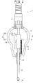
Fig. 2 shows an internal arrangement of the dial gauge according to the exemplary embodiment. -
Fig. 3 is a cross sectional view showing a braking device according to the exemplary embodiment. -
Fig. 4 is a cross sectional view showing the braking device when a spindle is moved down according to the exemplary embodiment. -
Fig. 5 is a front view showing the dial gauge when the spindle is moved up according to the exemplary embodiment. -
Fig. 6 is a cross sectional view showing the braking device when the spindle is moved up according to the exemplary embodiment. -
Fig. 7 is a cross sectional view showing a braking device according to a modification of the invention. -
Fig. 8 is a cross sectional view showing a braking device according to another modification of the invention. -
Fig. 9 is a cross sectional view showing a lift mechanism mounted to the braking device according to the another modification of the invention. -
Fig. 10 shows a traditional braking device of a spindle. - Exemplary embodiment(s) of the invention will be described below with reference to the attached drawings.
- As shown in
Figs. 1 and2 , a dial gauge 1 of the exemplary embodiment includes: abody case 2; aspindle 3 that penetrates thebody case 2 to be axially and reciprocably displaceable; abiasing unit 4 that axially biases thespindle 3 toward a first end (the lower end inFig. 2 ); adisplacement detector 5 that detects a displacement of thespindle 3; adisplay 6 that displays the displacement detected by thedisplacement detector 5; and abraking device 7 that brakes a descending speed of thespindle 3 and includes a lifting mechanism for lifting thespindle 3 toward a second end (the upper end inFig. 2 ). - The
body case 2 includes anaccommodating space 21 therein and astem 22 for guiding a substantially middle portion of thespindle 3 at the lower end. - The
spindle 3 includes aprobe 31 having a predetermined rigidity at the lower end. - The biasing
unit 4 is provided by acoil spring 42 of which a lower end is fixed to thebody case 2 and of which an upped end is fixed to asupport piece 41 that is displaced in conjunction with thespindle 3. - The
displacement detector 5 includes ascale 52 fixed to thespindle 3 via anattachment 51 to be parallel to thespindle 3; and a detectingsection 53 fixed to thebody case 2 being spaced apart from thescale 52 by a predetermined distance for detecting a displacement of thescale 52. The displacement detected by thedisplacement detector 5 is sent to thedisplay 6. - The
display 6 is provided by aliquid crystal panel 61 or the like arranged in a front middle portion of thebody case 2. - As shown in
Fig. 3 , thebraking device 7 includes: acylinder 71 of which a lower end is fitted to the upper end of thebody case 2 for communicating with theaccommodating space 21 of thebody case 2; apiston 72 that is provided on the upper end of thespindle 3 and is reciprocably displaceable within thecylinder 71; acap 73 detachably screwed to the upper end of thecylinder 71; a closingmember 74 placed between thecap 73 and the upper end surface of thecylinder 71; ashaft 75 connected to a side of thepiston 72 opposite to thespindle 3 and extends to penetrate the center of the closingmember 74 and thecap 73; and aknob 76 serving as an operating section provided on the distal end (upper end) of theshaft 75. - An
external thread 71 A is provided on the outer circumference at the upper end of thecylinder 71. - The
piston 72 is a disk, of which an outer diameter is slightly smaller than the inner diameter of thecylinder 71. - The
cap 73 prevents the closingmember 74 from being displaced beyond a predetermined distance in the axial direction of theshaft 75. Aninternal thread 73A that is screwed with theexternal thread 71A of thecylinder 71 is provided on the inner circumference of thecap 73, and a throughhole 73B is provided at the center of thecap 73. - The closing
member 74 includes a throughhole 74A into which theshaft 75 is inserted. The closingmember 74 is displaceable between the second end surface of thecylinder 71 and thecap 73 in the axial direction of theshaft 75, and forms adamper chamber 77 between the closingmember 74 and thepiston 72 when the closingmember 74 is in contact with the upper end surface of thecylinder 71. Aclearance 78 is provided between the throughhole 74A of the closingmember 74 and theshaft 75 to circulate air between thedamper chamber 77 and the outside thereof. Incidentally, the closingmember 74 may be made of metal or resin. - As shown in
Fig. 4 , when thespindle 3 is moved down by the biasing force of thebiasing unit 4 or the weight of thespindle 3, thepiston 72 is also moved down in conjunction with thespindle 3. Accordingly, the volume of thedamper chamber 77 is expanded and the pressure in thedamper chamber 77 is reduced, thereby braking the movement of thespindle 3. - Since the
clearance 78 is provided to circulate air between the closingmember 74 defining thedamper chamber 77 and theshaft 75 connected to thepiston 72, the air is gradually delivered into thedamper chamber 77 through theclearance 78, thereby moving thespindle 3 while braking the movement of thespindle 3. In other words, a damper effect can be obtained. - As shown in
Fig. 5 , theknob 76 is pulled up from a state where thespindle 3 is moved down. Then, as shown inFig. 6 , theshaft 75 is moved up, and thepiston 72 and thespindle 3 that are connected with theshaft 75 are also moved up. In other words, thespindle 3 can be lifted. - When the
piston 72 is moved up, the volume of thedamper chamber 77 is reduced and the pressure in thedamper chamber 77 is increased. Then, air within thedamper chamber 77 is discharged through theclearance 78 provided between the closingmember 74 and theshaft 75 while pushing up the closingmember 74 along theshaft 75. Accordingly, the closingmember 74 is spaced apart from the upper end surface of thecylinder 71 to provide a large clearance between the closingmember 74 and the upper end surface of thecylinder 71, so that the air within thedamper chamber 77 is discharged through this clearance to the outside. Consequently, a damper effect cannot be produced, so that thespindle 3 can be lifted by a small force. -
- (1) Since the
braking device 7 includes: thecylinder 71 mounted to thebody case 2; thepiston 72 that is provided on the upper end of thespindle 3 and accommodated to be reciprocably displaceable in thecylinder 71; the closingmember 74 placed on the upper end of thecylinder 71 to define thedamper chamber 77 between the closingmember 74 and thepiston 72; theshaft 75 connected to a side of thepiston 72 opposite to thespindle 3 and penetrates the closingmember 74; and theknob 76 provided on the distal end of theshaft 75, thebraking device 7 can provide a lift mechanism for thespindle 3. Thus, the descent of thespindle 3 can be braked without impairing ease of use. - (2) Since the closing
member 74 is displaceable in the axial direction of theshaft 75 and contactable to the upper end surface of thecylinder 71, when theshaft 75 is pulled up by theknob 76, the closingmember 74 is displaced in the axial direction of theshaft 75 by the pressure of thedamper chamber 77 to be spaced apart from the upper end surface of thecylinder 71. Thus, the large clearance is provided between the closingmember 74 and the upper end surface of thecylinder 71, so that the air within thedamper chamber 77 is discharged through this clearance. Consequently, the damper effect is hardly produced and therefore thespindle 3 can be lifted by a small force. - (3) Since the
cap 73 is provided on the second end of thecylinder 71 to prevent the closingmember 74 from being displaced beyond a predetermined distance in the axial direction of theshaft 75. Accordingly, the closingmember 74 is not significantly displaced in the axial direction of theshaft 75 while thespindle 3 is lifted. Thus, when thespindle 3 is moved down for next measurement, for instance, the closingmember 74 can be promptly brought into contact with the second end surface of thecylinder 71, whereby the damper effect can be readily produced. - The invention is not limited to the above-described embodiment, but includes modifications and improvements as long as an object of the invention can be achieved.
- Though the closing
member 74 is displaceable in the axial direction of theshaft 75 between the upper end surface of thecylinder 71 and thecap 73 in the exemplary embodiment, the closingmember 74 is not limited thereto. - For example, as shown in
Fig. 7 , the closingmember 74 may be displaceable in the axial direction of theshaft 75 on the external side of thecap 73, i.e., between thecap 73 and theknob 76 to attain the same advantages. - Also, the closing
member 74 may not be displaceable in the axial direction of theshaft 75. The closingmember 74 may be fixed to the second end surface of thecylinder 71 or fixed to the external side of thecap 73. - Though the
shaft 75 including theknob 76 is integrated with thepiston 72 to provide the lifting mechanism for lifting thespindle 3 by theshaft 75, the closingmember 74 and thecap 73 in the exemplary embodiment, the mechanism of the invention is not limited thereto. - For example, as shown in
Fig. 8 , theshaft 75 may be detachably provided on thepiston 72, and a circulatinghole 82 extending from the center of thepiston 72 to the outer circumference of thespindle 3 may be provided so as to gradually circulate the air between thedamper chamber 77 and a chamber 81 (i.e., the chamber communicating with theaccommodating space 21 of the body case 2) interposing thepiston 72 therebetween. With such an arrangement, by detaching theshaft 75 from thepiston 72 and covering the upper end of thecylinder 71 with acover cap 83 or the like, only thebraking device 7 can be provided without providing a lifting mechanism. - Incidentally, for providing the
shaft 75 that is detachable from thepiston 72, for instance, ascrew hole 84 may be provided on the center of thepiston 72 and an external thread 85 (seeFig. 9 ) screwed with thescrew hole 84 may be provided on theshaft 75. - Also, the circulating
hole 82 may not extend from the center of thepiston 72 to the outer circumference of thespindle 3. The circulatinghole 82 may penetrate both surfaces of thepiston 72. - When the circulating
hole 82 extends from the center of thepiston 72 to the outer circumference of thespindle 3, the pressure of thedamper chamber 77 is reduced by the descent of thespindle 3, thereby braking the movement of thespindle 3. At this time, the air gradually enters into thedamper chamber 77, so that thespindle 3 is moved while being braked, i.e., the damper effect can be produced. - When the arrangements shown in
Fig. 8 are initially employed and subsequently theshaft 75 including theknob 76 at the distal end is connected to thepiston 72, the braking device can include the lifting mechanism. In other words, when thecover cap 83 is removed to provide the closingmember 74 on the second end surface of thecylinder 71 while thecap 73 is screwed with the upper end of thecylinder 71 and theshaft 75 including theknob 76 at the distal end is screwed with thepiston 72 as shown inFig. 9 , thebraking device 7 can include the lifting mechanism afterward. - Though the lower end (the end closer to the body case 2) of the
cylinder 71 is opened to communicate between thecylinder 71 and theaccommodating space 21 of thebody case 2 in the exemplary embodiment, the lower end of thecylinder 71 may be hermetically sealed with thebush 101 as in the braking device disclosed inJP-A-59-170701
Claims (5)
- A braking device of a measuring instrument comprising a body case (2) and a spindle (3) that penetrates the body case (2) to be axially and reciprocably displaceable and includes a probe (31) at a first end, the braking device comprising:a cylinder (71) of which a first end is attached to the body case (2) for accommodating a second end of the spindle (3);a piston (72) provided on the second end of the spindle (3) and accommodated to be reciprocably displaceable within the cylinder (71);a closing member (74) provided on a second end of the cylinder (71) to form a damper chamber (77) between the piston (72) and the closing member (74);a shaft (75) that is opposite to the spindle (3) by interposing the piston (72) therebetween and penetrates the closing member (74); andan operating section (76) provided on a distal end of the shaft (75), whereina clearance (78) is provided between the closing member (74) and the shaft (75) for circulating air between the damper chamber (77) and an outside.
- The braking device of the measuring instrument according to claim 1, wherein
the closing member (74) is displaceable in an axial direction of the shaft (75) and contactable to a second end surface of the cylinder (71). - The braking device of the measuring instrument according to claim 2, wherein
a cap (73) is provided on the second end of the cylinder (71) to cover the closing member (74) and prevent the closing member (74) from being displaced beyond a predetermined distance in the axial direction of the shaft (75). - The braking device of the measuring instrument according to any one of claims 1 to 3, wherein
the shaft (75) is detachable from the piston (72), and
a circulating hole (82) is provided on the piston (72) or on both of the piston (72) and the spindle (3) to communicate between the damper chamber (77) and a chamber (81) opposite to the damper chamber (77) by interposing the piston (72) therebetween for circulating air. - A measuring device comprising:a body case (2);a spindle (3) that penetrates the body case (2) to be axially and reciprocably displaceable and includes a probe (31) at a first end;a biasing unit (4) that biases the spindle (3) toward the first end; andthe braking device (7) according to any one of claims 1 to 4.
Applications Claiming Priority (1)
| Application Number | Priority Date | Filing Date | Title |
|---|---|---|---|
| JP2008152804A JP5265970B2 (en) | 2008-06-11 | 2008-06-11 | Measuring device braking device and measuring device |
Publications (2)
| Publication Number | Publication Date |
|---|---|
| EP2133656A1 true EP2133656A1 (en) | 2009-12-16 |
| EP2133656B1 EP2133656B1 (en) | 2015-05-27 |
Family
ID=41010421
Family Applications (1)
| Application Number | Title | Priority Date | Filing Date |
|---|---|---|---|
| EP09162158.1A Active EP2133656B1 (en) | 2008-06-11 | 2009-06-08 | Braking device of measuring instrument and measuring instrument |
Country Status (4)
| Country | Link |
|---|---|
| US (1) | US7963047B2 (en) |
| EP (1) | EP2133656B1 (en) |
| JP (1) | JP5265970B2 (en) |
| CN (1) | CN101603801B (en) |
Families Citing this family (1)
| Publication number | Priority date | Publication date | Assignee | Title |
|---|---|---|---|---|
| CN103115538B (en) * | 2013-01-17 | 2015-07-29 | 杭州达禹精密仪器有限公司 | Clock gauge erecting frame and clock gauge |
Citations (4)
| Publication number | Priority date | Publication date | Assignee | Title |
|---|---|---|---|---|
| DE1005744B (en) * | 1955-10-22 | 1957-04-04 | Zeiss Carl Fa | Fine probe, especially for measuring highly sensitive surfaces |
| US4385446A (en) * | 1980-02-08 | 1983-05-31 | Piere Roch S.A.R.L. | Pistol-grip instrument for measurement of inside diameters |
| JPS59170701A (en) | 1983-03-16 | 1984-09-27 | Mitsutoyo Mfg Co Ltd | Digital display type size measuring instrument |
| FR2554921A1 (en) * | 1983-11-16 | 1985-05-17 | Kirov Instr Z Kr | Dial type instrument display |
Family Cites Families (7)
| Publication number | Priority date | Publication date | Assignee | Title |
|---|---|---|---|---|
| US1433076A (en) * | 1921-08-17 | 1922-10-24 | Fed Products Corp | Gauge |
| US2663945A (en) * | 1950-09-01 | 1953-12-29 | Standard Gage Co Inc | Shockproof dial indicator gauge |
| US2832151A (en) * | 1955-10-21 | 1958-04-29 | Emery Alfred Hamilton | Adjustable dial indicator gages |
| US3216118A (en) * | 1963-06-14 | 1965-11-09 | Pistoles Lambert Robert | Dial indicator |
| JPH0573504U (en) * | 1992-03-05 | 1993-10-08 | 株式会社ミツトヨ | Release |
| US5473822A (en) * | 1994-06-03 | 1995-12-12 | Js Research And Development, Inc. | Continuous air flow probe transducer gage assembly |
| JP4749708B2 (en) * | 2004-12-20 | 2011-08-17 | 株式会社ミツトヨ | Spindle braking device and measuring instrument |
-
2008
- 2008-06-11 JP JP2008152804A patent/JP5265970B2/en active Active
-
2009
- 2009-06-08 EP EP09162158.1A patent/EP2133656B1/en active Active
- 2009-06-09 US US12/481,232 patent/US7963047B2/en active Active
- 2009-06-10 CN CN2009102037368A patent/CN101603801B/en active Active
Patent Citations (5)
| Publication number | Priority date | Publication date | Assignee | Title |
|---|---|---|---|---|
| DE1005744B (en) * | 1955-10-22 | 1957-04-04 | Zeiss Carl Fa | Fine probe, especially for measuring highly sensitive surfaces |
| US4385446A (en) * | 1980-02-08 | 1983-05-31 | Piere Roch S.A.R.L. | Pistol-grip instrument for measurement of inside diameters |
| JPS59170701A (en) | 1983-03-16 | 1984-09-27 | Mitsutoyo Mfg Co Ltd | Digital display type size measuring instrument |
| US4566201A (en) * | 1983-03-16 | 1986-01-28 | Mitutoyo Mfg. Co., Ltd. | Digital indicating type dimension measuring instrument |
| FR2554921A1 (en) * | 1983-11-16 | 1985-05-17 | Kirov Instr Z Kr | Dial type instrument display |
Also Published As
| Publication number | Publication date |
|---|---|
| JP2009300156A (en) | 2009-12-24 |
| US20090308699A1 (en) | 2009-12-17 |
| EP2133656B1 (en) | 2015-05-27 |
| CN101603801A (en) | 2009-12-16 |
| US7963047B2 (en) | 2011-06-21 |
| JP5265970B2 (en) | 2013-08-14 |
| CN101603801B (en) | 2012-10-24 |
Similar Documents
| Publication | Publication Date | Title |
|---|---|---|
| DK2998583T3 (en) | Pressure gauge for an air compressor | |
| DK3001165T3 (en) | Pressure indicator with pressure relief function | |
| US20110180360A1 (en) | Overpressure and bottoming detector for a shock-absorber or the like | |
| CN106225680A (en) | A kind of spool displacement measurement apparatus based on laser displacement sensor and method | |
| US4566201A (en) | Digital indicating type dimension measuring instrument | |
| JP2025503481A (en) | Electromechanical Cylinder | |
| EP2133656B1 (en) | Braking device of measuring instrument and measuring instrument | |
| CN104964877B (en) | A kind of device for testing stiffness and system | |
| JP4885884B2 (en) | Elevator motor brake torque measurement device | |
| US9551559B2 (en) | Compact 3D contact measuring device | |
| KR20100111087A (en) | Pressure measuring apparatus having over-pressure safety valve | |
| KR102365105B1 (en) | Push-pull gage for an elevator, escalator and moving walk | |
| JP3683756B2 (en) | Leak measuring instrument | |
| JP3156443B2 (en) | Liquid level detector | |
| CN214747782U (en) | Pneumatic driving miniature grating ruler | |
| JP4580673B2 (en) | Measuring instrument | |
| JP6985857B2 (en) | Length measuring instrument and length measuring system | |
| CN106744147B (en) | Hydraulic elevator buffer | |
| JP4749708B2 (en) | Spindle braking device and measuring instrument | |
| US7677116B2 (en) | Force sensor device in a two-wheeled vehicle | |
| CN102589601A (en) | Measuring gauge with additional indicator for overloads | |
| CN220366846U (en) | Inductive sensor and measuring head lifting mechanism | |
| RU2287790C1 (en) | Excess pressure registrar | |
| CN113091621B (en) | A pneumatically driven micro grating ruler | |
| JP2009036721A (en) | Spindle braking device and measuring instrument |
Legal Events
| Date | Code | Title | Description |
|---|---|---|---|
| PUAI | Public reference made under article 153(3) epc to a published international application that has entered the european phase |
Free format text: ORIGINAL CODE: 0009012 |
|
| AK | Designated contracting states |
Kind code of ref document: A1 Designated state(s): AT BE BG CH CY CZ DE DK EE ES FI FR GB GR HR HU IE IS IT LI LT LU LV MC MK MT NL NO PL PT RO SE SI SK TR |
|
| 17P | Request for examination filed |
Effective date: 20100615 |
|
| 17Q | First examination report despatched |
Effective date: 20141014 |
|
| GRAP | Despatch of communication of intention to grant a patent |
Free format text: ORIGINAL CODE: EPIDOSNIGR1 |
|
| INTG | Intention to grant announced |
Effective date: 20150224 |
|
| GRAS | Grant fee paid |
Free format text: ORIGINAL CODE: EPIDOSNIGR3 |
|
| GRAA | (expected) grant |
Free format text: ORIGINAL CODE: 0009210 |
|
| AK | Designated contracting states |
Kind code of ref document: B1 Designated state(s): AT BE BG CH CY CZ DE DK EE ES FI FR GB GR HR HU IE IS IT LI LT LU LV MC MK MT NL NO PL PT RO SE SI SK TR |
|
| REG | Reference to a national code |
Ref country code: GB Ref legal event code: FG4D |
|
| REG | Reference to a national code |
Ref country code: CH Ref legal event code: EP |
|
| REG | Reference to a national code |
Ref country code: AT Ref legal event code: REF Ref document number: 729096 Country of ref document: AT Kind code of ref document: T Effective date: 20150615 |
|
| REG | Reference to a national code |
Ref country code: IE Ref legal event code: FG4D |
|
| REG | Reference to a national code |
Ref country code: DE Ref legal event code: R096 Ref document number: 602009031400 Country of ref document: DE Effective date: 20150709 |
|
| REG | Reference to a national code |
Ref country code: AT Ref legal event code: MK05 Ref document number: 729096 Country of ref document: AT Kind code of ref document: T Effective date: 20150527 |
|
| REG | Reference to a national code |
Ref country code: LT Ref legal event code: MG4D |
|
| PG25 | Lapsed in a contracting state [announced via postgrant information from national office to epo] |
Ref country code: PT Free format text: LAPSE BECAUSE OF FAILURE TO SUBMIT A TRANSLATION OF THE DESCRIPTION OR TO PAY THE FEE WITHIN THE PRESCRIBED TIME-LIMIT Effective date: 20150928 Ref country code: FI Free format text: LAPSE BECAUSE OF FAILURE TO SUBMIT A TRANSLATION OF THE DESCRIPTION OR TO PAY THE FEE WITHIN THE PRESCRIBED TIME-LIMIT Effective date: 20150527 Ref country code: NO Free format text: LAPSE BECAUSE OF FAILURE TO SUBMIT A TRANSLATION OF THE DESCRIPTION OR TO PAY THE FEE WITHIN THE PRESCRIBED TIME-LIMIT Effective date: 20150827 Ref country code: ES Free format text: LAPSE BECAUSE OF FAILURE TO SUBMIT A TRANSLATION OF THE DESCRIPTION OR TO PAY THE FEE WITHIN THE PRESCRIBED TIME-LIMIT Effective date: 20150527 Ref country code: HR Free format text: LAPSE BECAUSE OF FAILURE TO SUBMIT A TRANSLATION OF THE DESCRIPTION OR TO PAY THE FEE WITHIN THE PRESCRIBED TIME-LIMIT Effective date: 20150527 Ref country code: LT Free format text: LAPSE BECAUSE OF FAILURE TO SUBMIT A TRANSLATION OF THE DESCRIPTION OR TO PAY THE FEE WITHIN THE PRESCRIBED TIME-LIMIT Effective date: 20150527 |
|
| REG | Reference to a national code |
Ref country code: NL Ref legal event code: MP Effective date: 20150527 |
|
| PG25 | Lapsed in a contracting state [announced via postgrant information from national office to epo] |
Ref country code: LV Free format text: LAPSE BECAUSE OF FAILURE TO SUBMIT A TRANSLATION OF THE DESCRIPTION OR TO PAY THE FEE WITHIN THE PRESCRIBED TIME-LIMIT Effective date: 20150527 Ref country code: AT Free format text: LAPSE BECAUSE OF FAILURE TO SUBMIT A TRANSLATION OF THE DESCRIPTION OR TO PAY THE FEE WITHIN THE PRESCRIBED TIME-LIMIT Effective date: 20150527 Ref country code: IS Free format text: LAPSE BECAUSE OF FAILURE TO SUBMIT A TRANSLATION OF THE DESCRIPTION OR TO PAY THE FEE WITHIN THE PRESCRIBED TIME-LIMIT Effective date: 20150927 Ref country code: GR Free format text: LAPSE BECAUSE OF FAILURE TO SUBMIT A TRANSLATION OF THE DESCRIPTION OR TO PAY THE FEE WITHIN THE PRESCRIBED TIME-LIMIT Effective date: 20150828 Ref country code: BG Free format text: LAPSE BECAUSE OF FAILURE TO SUBMIT A TRANSLATION OF THE DESCRIPTION OR TO PAY THE FEE WITHIN THE PRESCRIBED TIME-LIMIT Effective date: 20150827 |
|
| PG25 | Lapsed in a contracting state [announced via postgrant information from national office to epo] |
Ref country code: IT Free format text: LAPSE BECAUSE OF FAILURE TO SUBMIT A TRANSLATION OF THE DESCRIPTION OR TO PAY THE FEE WITHIN THE PRESCRIBED TIME-LIMIT Effective date: 20150527 Ref country code: DK Free format text: LAPSE BECAUSE OF FAILURE TO SUBMIT A TRANSLATION OF THE DESCRIPTION OR TO PAY THE FEE WITHIN THE PRESCRIBED TIME-LIMIT Effective date: 20150527 Ref country code: EE Free format text: LAPSE BECAUSE OF FAILURE TO SUBMIT A TRANSLATION OF THE DESCRIPTION OR TO PAY THE FEE WITHIN THE PRESCRIBED TIME-LIMIT Effective date: 20150527 |
|
| REG | Reference to a national code |
Ref country code: CH Ref legal event code: PL |
|
| PG25 | Lapsed in a contracting state [announced via postgrant information from national office to epo] |
Ref country code: SK Free format text: LAPSE BECAUSE OF FAILURE TO SUBMIT A TRANSLATION OF THE DESCRIPTION OR TO PAY THE FEE WITHIN THE PRESCRIBED TIME-LIMIT Effective date: 20150527 Ref country code: CZ Free format text: LAPSE BECAUSE OF FAILURE TO SUBMIT A TRANSLATION OF THE DESCRIPTION OR TO PAY THE FEE WITHIN THE PRESCRIBED TIME-LIMIT Effective date: 20150527 Ref country code: PL Free format text: LAPSE BECAUSE OF FAILURE TO SUBMIT A TRANSLATION OF THE DESCRIPTION OR TO PAY THE FEE WITHIN THE PRESCRIBED TIME-LIMIT Effective date: 20150527 Ref country code: RO Free format text: LAPSE BECAUSE OF NON-PAYMENT OF DUE FEES Effective date: 20150527 Ref country code: MC Free format text: LAPSE BECAUSE OF FAILURE TO SUBMIT A TRANSLATION OF THE DESCRIPTION OR TO PAY THE FEE WITHIN THE PRESCRIBED TIME-LIMIT Effective date: 20150527 |
|
| REG | Reference to a national code |
Ref country code: DE Ref legal event code: R097 Ref document number: 602009031400 Country of ref document: DE |
|
| REG | Reference to a national code |
Ref country code: IE Ref legal event code: MM4A |
|
| PLBE | No opposition filed within time limit |
Free format text: ORIGINAL CODE: 0009261 |
|
| STAA | Information on the status of an ep patent application or granted ep patent |
Free format text: STATUS: NO OPPOSITION FILED WITHIN TIME LIMIT |
|
| PG25 | Lapsed in a contracting state [announced via postgrant information from national office to epo] |
Ref country code: IE Free format text: LAPSE BECAUSE OF NON-PAYMENT OF DUE FEES Effective date: 20150608 Ref country code: LI Free format text: LAPSE BECAUSE OF NON-PAYMENT OF DUE FEES Effective date: 20150630 Ref country code: CH Free format text: LAPSE BECAUSE OF NON-PAYMENT OF DUE FEES Effective date: 20150630 |
|
| 26N | No opposition filed |
Effective date: 20160301 |
|
| PG25 | Lapsed in a contracting state [announced via postgrant information from national office to epo] |
Ref country code: SI Free format text: LAPSE BECAUSE OF FAILURE TO SUBMIT A TRANSLATION OF THE DESCRIPTION OR TO PAY THE FEE WITHIN THE PRESCRIBED TIME-LIMIT Effective date: 20150527 |
|
| REG | Reference to a national code |
Ref country code: FR Ref legal event code: ST Effective date: 20160722 |
|
| PG25 | Lapsed in a contracting state [announced via postgrant information from national office to epo] |
Ref country code: BE Free format text: LAPSE BECAUSE OF FAILURE TO SUBMIT A TRANSLATION OF THE DESCRIPTION OR TO PAY THE FEE WITHIN THE PRESCRIBED TIME-LIMIT Effective date: 20150527 |
|
| PG25 | Lapsed in a contracting state [announced via postgrant information from national office to epo] |
Ref country code: FR Free format text: LAPSE BECAUSE OF NON-PAYMENT OF DUE FEES Effective date: 20150727 |
|
| PG25 | Lapsed in a contracting state [announced via postgrant information from national office to epo] |
Ref country code: MT Free format text: LAPSE BECAUSE OF FAILURE TO SUBMIT A TRANSLATION OF THE DESCRIPTION OR TO PAY THE FEE WITHIN THE PRESCRIBED TIME-LIMIT Effective date: 20150527 |
|
| PG25 | Lapsed in a contracting state [announced via postgrant information from national office to epo] |
Ref country code: HU Free format text: LAPSE BECAUSE OF FAILURE TO SUBMIT A TRANSLATION OF THE DESCRIPTION OR TO PAY THE FEE WITHIN THE PRESCRIBED TIME-LIMIT; INVALID AB INITIO Effective date: 20090608 |
|
| PG25 | Lapsed in a contracting state [announced via postgrant information from national office to epo] |
Ref country code: NL Free format text: LAPSE BECAUSE OF FAILURE TO SUBMIT A TRANSLATION OF THE DESCRIPTION OR TO PAY THE FEE WITHIN THE PRESCRIBED TIME-LIMIT Effective date: 20150527 Ref country code: CY Free format text: LAPSE BECAUSE OF FAILURE TO SUBMIT A TRANSLATION OF THE DESCRIPTION OR TO PAY THE FEE WITHIN THE PRESCRIBED TIME-LIMIT Effective date: 20150527 Ref country code: SE Free format text: LAPSE BECAUSE OF FAILURE TO SUBMIT A TRANSLATION OF THE DESCRIPTION OR TO PAY THE FEE WITHIN THE PRESCRIBED TIME-LIMIT Effective date: 20150527 |
|
| PG25 | Lapsed in a contracting state [announced via postgrant information from national office to epo] |
Ref country code: TR Free format text: LAPSE BECAUSE OF FAILURE TO SUBMIT A TRANSLATION OF THE DESCRIPTION OR TO PAY THE FEE WITHIN THE PRESCRIBED TIME-LIMIT Effective date: 20150527 |
|
| PG25 | Lapsed in a contracting state [announced via postgrant information from national office to epo] |
Ref country code: LU Free format text: LAPSE BECAUSE OF NON-PAYMENT OF DUE FEES Effective date: 20150608 |
|
| PG25 | Lapsed in a contracting state [announced via postgrant information from national office to epo] |
Ref country code: MK Free format text: LAPSE BECAUSE OF FAILURE TO SUBMIT A TRANSLATION OF THE DESCRIPTION OR TO PAY THE FEE WITHIN THE PRESCRIBED TIME-LIMIT Effective date: 20150527 |
|
| PGFP | Annual fee paid to national office [announced via postgrant information from national office to epo] |
Ref country code: DE Payment date: 20250618 Year of fee payment: 17 |
|
| PGFP | Annual fee paid to national office [announced via postgrant information from national office to epo] |
Ref country code: GB Payment date: 20250618 Year of fee payment: 17 |