EP2133513A2 - Bearing system - Google Patents
Bearing system Download PDFInfo
- Publication number
- EP2133513A2 EP2133513A2 EP09250804A EP09250804A EP2133513A2 EP 2133513 A2 EP2133513 A2 EP 2133513A2 EP 09250804 A EP09250804 A EP 09250804A EP 09250804 A EP09250804 A EP 09250804A EP 2133513 A2 EP2133513 A2 EP 2133513A2
- Authority
- EP
- European Patent Office
- Prior art keywords
- bearing
- fore
- ring
- cage
- aft
- Prior art date
- Legal status (The legal status is an assumption and is not a legal conclusion. Google has not performed a legal analysis and makes no representation as to the accuracy of the status listed.)
- Granted
Links
Images


Classifications
-
- F—MECHANICAL ENGINEERING; LIGHTING; HEATING; WEAPONS; BLASTING
- F01—MACHINES OR ENGINES IN GENERAL; ENGINE PLANTS IN GENERAL; STEAM ENGINES
- F01D—NON-POSITIVE DISPLACEMENT MACHINES OR ENGINES, e.g. STEAM TURBINES
- F01D25/00—Component parts, details, or accessories, not provided for in, or of interest apart from, other groups
- F01D25/16—Arrangement of bearings; Supporting or mounting bearings in casings
-
- F—MECHANICAL ENGINEERING; LIGHTING; HEATING; WEAPONS; BLASTING
- F01—MACHINES OR ENGINES IN GENERAL; ENGINE PLANTS IN GENERAL; STEAM ENGINES
- F01D—NON-POSITIVE DISPLACEMENT MACHINES OR ENGINES, e.g. STEAM TURBINES
- F01D25/00—Component parts, details, or accessories, not provided for in, or of interest apart from, other groups
- F01D25/18—Lubricating arrangements
-
- F—MECHANICAL ENGINEERING; LIGHTING; HEATING; WEAPONS; BLASTING
- F16—ENGINEERING ELEMENTS AND UNITS; GENERAL MEASURES FOR PRODUCING AND MAINTAINING EFFECTIVE FUNCTIONING OF MACHINES OR INSTALLATIONS; THERMAL INSULATION IN GENERAL
- F16C—SHAFTS; FLEXIBLE SHAFTS; ELEMENTS OR CRANKSHAFT MECHANISMS; ROTARY BODIES OTHER THAN GEARING ELEMENTS; BEARINGS
- F16C33/00—Parts of bearings; Special methods for making bearings or parts thereof
- F16C33/30—Parts of ball or roller bearings
- F16C33/66—Special parts or details in view of lubrication
- F16C33/6637—Special parts or details in view of lubrication with liquid lubricant
- F16C33/6659—Details of supply of the liquid to the bearing, e.g. passages or nozzles
- F16C33/6677—Details of supply of the liquid to the bearing, e.g. passages or nozzles from radial inside, e.g. via a passage through the shaft and/or inner ring
-
- F—MECHANICAL ENGINEERING; LIGHTING; HEATING; WEAPONS; BLASTING
- F16—ENGINEERING ELEMENTS AND UNITS; GENERAL MEASURES FOR PRODUCING AND MAINTAINING EFFECTIVE FUNCTIONING OF MACHINES OR INSTALLATIONS; THERMAL INSULATION IN GENERAL
- F16C—SHAFTS; FLEXIBLE SHAFTS; ELEMENTS OR CRANKSHAFT MECHANISMS; ROTARY BODIES OTHER THAN GEARING ELEMENTS; BEARINGS
- F16C33/00—Parts of bearings; Special methods for making bearings or parts thereof
- F16C33/30—Parts of ball or roller bearings
- F16C33/66—Special parts or details in view of lubrication
- F16C33/6637—Special parts or details in view of lubrication with liquid lubricant
- F16C33/6685—Details of collecting or draining, e.g. returning the liquid to a sump
-
- F—MECHANICAL ENGINEERING; LIGHTING; HEATING; WEAPONS; BLASTING
- F16—ENGINEERING ELEMENTS AND UNITS; GENERAL MEASURES FOR PRODUCING AND MAINTAINING EFFECTIVE FUNCTIONING OF MACHINES OR INSTALLATIONS; THERMAL INSULATION IN GENERAL
- F16C—SHAFTS; FLEXIBLE SHAFTS; ELEMENTS OR CRANKSHAFT MECHANISMS; ROTARY BODIES OTHER THAN GEARING ELEMENTS; BEARINGS
- F16C19/00—Bearings with rolling contact, for exclusively rotary movement
- F16C19/02—Bearings with rolling contact, for exclusively rotary movement with bearing balls essentially of the same size in one or more circular rows
- F16C19/04—Bearings with rolling contact, for exclusively rotary movement with bearing balls essentially of the same size in one or more circular rows for radial load mainly
- F16C19/06—Bearings with rolling contact, for exclusively rotary movement with bearing balls essentially of the same size in one or more circular rows for radial load mainly with a single row or balls
-
- F—MECHANICAL ENGINEERING; LIGHTING; HEATING; WEAPONS; BLASTING
- F16—ENGINEERING ELEMENTS AND UNITS; GENERAL MEASURES FOR PRODUCING AND MAINTAINING EFFECTIVE FUNCTIONING OF MACHINES OR INSTALLATIONS; THERMAL INSULATION IN GENERAL
- F16C—SHAFTS; FLEXIBLE SHAFTS; ELEMENTS OR CRANKSHAFT MECHANISMS; ROTARY BODIES OTHER THAN GEARING ELEMENTS; BEARINGS
- F16C19/00—Bearings with rolling contact, for exclusively rotary movement
- F16C19/22—Bearings with rolling contact, for exclusively rotary movement with bearing rollers essentially of the same size in one or more circular rows, e.g. needle bearings
- F16C19/24—Bearings with rolling contact, for exclusively rotary movement with bearing rollers essentially of the same size in one or more circular rows, e.g. needle bearings for radial load mainly
- F16C19/26—Bearings with rolling contact, for exclusively rotary movement with bearing rollers essentially of the same size in one or more circular rows, e.g. needle bearings for radial load mainly with a single row of rollers
-
- F—MECHANICAL ENGINEERING; LIGHTING; HEATING; WEAPONS; BLASTING
- F16—ENGINEERING ELEMENTS AND UNITS; GENERAL MEASURES FOR PRODUCING AND MAINTAINING EFFECTIVE FUNCTIONING OF MACHINES OR INSTALLATIONS; THERMAL INSULATION IN GENERAL
- F16C—SHAFTS; FLEXIBLE SHAFTS; ELEMENTS OR CRANKSHAFT MECHANISMS; ROTARY BODIES OTHER THAN GEARING ELEMENTS; BEARINGS
- F16C2360/00—Engines or pumps
- F16C2360/23—Gas turbine engines
-
- F—MECHANICAL ENGINEERING; LIGHTING; HEATING; WEAPONS; BLASTING
- F16—ENGINEERING ELEMENTS AND UNITS; GENERAL MEASURES FOR PRODUCING AND MAINTAINING EFFECTIVE FUNCTIONING OF MACHINES OR INSTALLATIONS; THERMAL INSULATION IN GENERAL
- F16C—SHAFTS; FLEXIBLE SHAFTS; ELEMENTS OR CRANKSHAFT MECHANISMS; ROTARY BODIES OTHER THAN GEARING ELEMENTS; BEARINGS
- F16C33/00—Parts of bearings; Special methods for making bearings or parts thereof
- F16C33/30—Parts of ball or roller bearings
- F16C33/58—Raceways; Race rings
- F16C33/583—Details of specific parts of races
- F16C33/586—Details of specific parts of races outside the space between the races, e.g. end faces or bore of inner ring
Definitions
- This disclosure relates to a bearing system for a gas turbine engine, and more particularly to a lubrication arrangement for a bearing system configuration that reduces stress levels on bearing components.
- a typical bearing assembly includes an inner ring, an outer ring radially spaced from the inner ring, and a cage positioned between the inner and outer rings that holds a plurality of roller or bearing elements.
- a lubrication system is used to provide lubricating fluid to the bearing elements.
- the inner ring includes axial slots that extend in a direction of the engine axis and a plurality of radial holes that extend radially outwardly toward the cage. Lubricating fluid is delivered to the axial slots and is communicated to the bearing elements via the radial holes.
- the bearing assembly can be subjected to relatively high centrifugal loads, high assembly loads, and/or high operating loads that result in relatively high stress levels on individual components of the bearing assembly, such as the inner ring for example.
- the stress levels on a component such as the inner ring may be amplified by the particular arrangement of the slots and holes. For example, at an intersection between the axial slots and the radial holes may amplify stresses in the inner ring.
- An example bearing system includes an inner ring that surrounds an axis of rotation, an outer ring spaced radially outwards from the inner ring, and a cage that is positioned between the inner and outer rings to support a plurality of bearing elements.
- the inner ring includes at least one axial slot that extends in a direction along the axis of rotation.
- the inner ring also includes at least one radial side slot formed in at least one of a fore and aft end surface of the inner ring. The radial side slot directs lubricating fluid from the axial slot toward the cage to lubricate the plurality of bearing elements.
- the radial side slot is formed in one of the fore and aft end surfaces of the inner ring and at least one fluid nozzle is positioned near the other of the fore and aft end surfaces.
- the radial side slot directs lubricating fluid toward one of fore and aft edges of the cage, and the fluid nozzle directs lubricating fluid toward the other of the fore and aft edges of the cage.
- the bearing system is included in a turbine engine.
- a method of delivering lubricating fluid to a bearing system includes dispensing lubricating fluid to bearing elements through a radial side slot formed within at least one of the fore and aft end surfaces of the inner ring.
- Figure 1 illustrates selected portions of an example turbine engine 10, such as a gas turbine engine 10 used for propulsion.
- the gas turbine engine 10 is circumferentially disposed about an engine centerline 12.
- the gas turbine engine 10 includes a fan section 14, a compressor section 16, a combustion section 18, and a turbine section 20.
- the compressor section 16 and the turbine section 20 include corresponding blades 22 and vanes 24.
- the turbine section 20 includes a high pressure turbine (HPT) section 20a and a low pressure turbine (LPT) section 20b.
- the compressor section 16 includes a high pressure compressor (HPC) section 16a and a low pressure compressor (LPC) section 16b.
- HPC high pressure compressor
- LPC low pressure compressor
- Figure 1 is for illustrative purposes only and is not a limitation on the disclosed examples. Additionally, there are various other types of gas turbine engines, such as geared architecture engines, which could utilize the examples disclosed herein.
- the gas turbine-engine 10 includes a bearing system 30 associated with a shaft 32 that rotates about an axis of rotation defined by the engine centerline 12.
- the shaft 32 in this example rotates the HPT section 20a of the turbine section 20 and the HPC section 16a of the compressor section 16.
- the bearing system 30 may also be applied to other portions of an engine, such as a low pressure shaft 34 for example, or to other types of machines.
- the bearing system 30 includes a first or inner ring 36 that surrounds the axis of rotation and is coupled in a known manner with the shaft 32, and a second or outer ring 38 that is spaced radially outwards from the inner ring 36 in a direction away from the axis of rotation.
- a bearing cage 40 is located between the inner ring 36 and the outer ring 38.
- the bearing cage 40 includes a circumferential outer surface 42, a circumferential inner surface 44, and a plurality of circumferentially spaced retainer portions 46 that are located between an axially fore end 48 and an axially trailing or aft end 50.
- a plurality of bearing elements 52 are supported within the circumferentially spaced retainer portions 46 as known.
- the bearing elements 52 may be any of the various types of bearing elements known in the art, including cylindrical, ball, tapered, etc.
- the inner ring 36 includes an inner circumferential surface 54 that surrounds the axis of rotation and an outer circumferential surface 56 that is spaced radially outwardly from the inner circumferential surface 54.
- a fore end surface 58 extends in a radial direction from the inner circumferential surface 54 to the outer circumferential surface 56.
- An aft end surface 60 is axially spaced from the fore end surface 58 and extends in a radial direction from the inner circumferential surface 54 to the outer circumferential surface 56.
- the fore 58 and aft 60 end surfaces define opposing side edges of the inner ring 36.
- the inner ring 36 includes a raceway 70 that is located between a forward or fore ring land 72 and a trailing or aft ring land 74 that generally protrude radially outwards from the raceway 70.
- the bearing elements 52 are located within the retainer portions 46 ( Figure 3 ) of the bearing cage 40 and are positioned in the raceway 70 axially between the fore 72 and aft 74 ring lands.
- At least one fluid passage or axial slot 62 is formed in the inner ring 36.
- the axial slot 62 is formed within the inner circumferential surface 54 and extends in a direction along the axis of rotation.
- the axial slot 62 is in fluid communication with a lubrication system 64 ( Figure 2 ) of the gas turbine engine 10, which delivers lubricating fluid, such as oil for example, to the bearing elements 52.
- At least one radial side slot 66 is formed in at least one of the fore 58 and aft 60 end surfaces of the inner ring 36.
- the radial side slot 66 extends in a radial direction that extends outwardly from the axis of rotation. In the example shown in Figures 4A-4B and 5A-5B , the radial side slot 66 is formed within the aft end surface 60.
- the radial side slot 66 provides a fluid passage such that lubricating fluid can be dispensed from the axial slot 62 toward the bearing cage 40.
- the radial side slot 66 is formed in one of the fore 58 and aft 60 end surfaces of the inner ring 36.
- At least one fluid nozzle 68 is positioned near the other of the fore 58 and aft 60 end surfaces of the inner ring 36.
- the fluid nozzle 68 is axially spaced from the bearing cage 40 near the fore end surface 58 of the inner ring 36.
- the fluid nozzle 68 dispenses lubricating fluid to the bearing elements 52 by directing the fluid toward a gap 88 formed between the circumferential inner surface 44 of the bearing cage 40 and the outer circumferential surface 56 of the inner ring 36.
- the fluid nozzle 68 is also in fluid communication with the lubrication system 64 of the gas turbine engine 10. By supplying lubricating fluid through the fluid nozzle 68 and the radial side slot 66 the need for radial holes that extend radially from the axial slot 62 through the body of the inner ring is eliminated.
- the lubrication system 64 delivers lubricating fluid to the fluid nozzle 68 and to the axial slot 62.
- the lubrication system 64 is a known configuration and includes, for illustratively purposes only, a pump to move the lubricating fluid through the lubrication system 64.
- the lubricating fluid flows through the axial slot 62 along the inner circumferential surface 54 of the inner ring 36 and into the radial side slot 66 in the aft end surface 60 of the inner ring 36.
- the radial side slot 66 directs the lubricating fluid against the circumferential inner surface 44 of the bearing cage 40 near the aft end 50 of the bearing cage 40.
- the lubricating fluid is then directed along the circumferential inner surface 44 of the bearing cage 40 toward the bearing elements 52.
- the lubrication system 64 may provide more lubricating fluid than required for the bearing system 30.
- the bearing system 30 may also include a runner plate 80 adjacent the aft ring land 74 of the inner ring 36.
- the runner plate 80 may include at least one fluid passage 82 for receiving surplus lubricating fluid supplied by the axial slot 62 of the inner ring 36.
- the fluid passage 82 serves to collect the surplus fluid and circulates the surplus fluid back into the lubrication system 64.
- Figures 5A-5B show another example of a bearing system. This configuration is similar to that of Figures 4A-4B ; however the inner ring 36 comprises a split ring.
- the split ring includes an aft ring piece 100 and a fore ring piece 102 that is axially spaced apart from the aft ring piece 100 by a gap 104.
- At least one radial side slot 106 is formed in an aft end surface 118 of the aft ring piece 100 similar to the radial side slot 66.
- another radial side slot 108 is formed at the gap 104.
- the aft ring piece 100 includes a fore face 110 that faces an aft face 112 of the fore ring piece 102.
- the fore 110 and aft 112 faces are separated by the gap 104.
- the radial side slot 108 is formed in one of the fore 110 and aft 112 faces.
- the radial side slots 106, 108 direct fluid from axial slots 116 formed within the aft 100 and fore 102 ring pieces toward the bearing cage 40 and bearing elements 52 in a manner similar to that described above with regard to Figures 4A-4B .
- the fluid nozzle 68 may also be used in a manner similar to that shown in Figures 4A-4B .
- annulus 120 is included to facilitate distribution of the lubricating fluid.
- the annulus 120 is formed at a transition between the axial slot 62, 116 and the radial side slot 66, 106.
- the annulus 120 is defined by a tapered surface 122 that transitions from an inner circumferential surface of the inner ring to the aft end surface 60, 118 of the inner ring.
- the tapered surface 122 defines a plane that is obliquely oriented to the axis of rotation.
- Lubricating fluid is delivered to the annulus 120 via the axial slots 62, 116 where it is collected and then dispensed toward the bearing cage 40 via the radial side slots 66, 106 as described above.
- the axial slots, radial side slots, and annulus cooperate to efficiently dispense lubricating fluid to the bearing elements.
- the disclosed bearing systems minimize inner ring stress by eliminating the need for radial holes extending through the inner ring and creating high stress concentrations where the hole and bore slot features intersect.
- the intersection of the side slot(s) with the annulus at the inner ring end face have significantly lower stress concentration levels.
- each inner ring could include a plurality of axial slots and radial side slots.
- Figure 6 shows an example that includes a three slot configuration.
- the inner ring 36 or aft ring piece 100 includes three axial slots 62, 116 and three radial side slots 66, 108 that are formed within an aft end surface 60, 118 of the inner ring 36 or aft ring piece 100.
- the slots in this example are spaced approximate 120 degrees apart from each other; however other spacing configurations could also be used. Also, additional slots can be added or slots can be eliminated depending upon varying specifications.
Landscapes
- Engineering & Computer Science (AREA)
- General Engineering & Computer Science (AREA)
- Mechanical Engineering (AREA)
- Rolling Contact Bearings (AREA)
Abstract
Description
- This disclosure relates to a bearing system for a gas turbine engine, and more particularly to a lubrication arrangement for a bearing system configuration that reduces stress levels on bearing components.
- Gas turbine engines utilize bearing assemblies at various locations throughout the engine to support components for rotation about an engine axis. A typical bearing assembly includes an inner ring, an outer ring radially spaced from the inner ring, and a cage positioned between the inner and outer rings that holds a plurality of roller or bearing elements.
- A lubrication system is used to provide lubricating fluid to the bearing elements. Traditionally, the inner ring includes axial slots that extend in a direction of the engine axis and a plurality of radial holes that extend radially outwardly toward the cage. Lubricating fluid is delivered to the axial slots and is communicated to the bearing elements via the radial holes.
- The bearing assembly can be subjected to relatively high centrifugal loads, high assembly loads, and/or high operating loads that result in relatively high stress levels on individual components of the bearing assembly, such as the inner ring for example. The stress levels on a component such as the inner ring may be amplified by the particular arrangement of the slots and holes. For example, at an intersection between the axial slots and the radial holes may amplify stresses in the inner ring.
- Thus, there is a need for a lubrication arrangement that reduces stress levels experienced by bearing components.
- An example bearing system includes an inner ring that surrounds an axis of rotation, an outer ring spaced radially outwards from the inner ring, and a cage that is positioned between the inner and outer rings to support a plurality of bearing elements. The inner ring includes at least one axial slot that extends in a direction along the axis of rotation. The inner ring also includes at least one radial side slot formed in at least one of a fore and aft end surface of the inner ring. The radial side slot directs lubricating fluid from the axial slot toward the cage to lubricate the plurality of bearing elements.
- In one example, the radial side slot is formed in one of the fore and aft end surfaces of the inner ring and at least one fluid nozzle is positioned near the other of the fore and aft end surfaces. The radial side slot directs lubricating fluid toward one of fore and aft edges of the cage, and the fluid nozzle directs lubricating fluid toward the other of the fore and aft edges of the cage.
- In one example, the bearing system is included in a turbine engine.
- In one example, a method of delivering lubricating fluid to a bearing system is also provided. For example, the method includes dispensing lubricating fluid to bearing elements through a radial side slot formed within at least one of the fore and aft end surfaces of the inner ring.
- The various features and advantages of this invention will become apparent to those skilled in the art from the following detailed description of the currently preferred embodiment. The drawings that accompany the detailed description can be briefly described as follows.
-
Figure 1 illustrates an example gas turbine engine including a bearing system. -
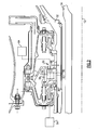
Figure 2 illustrates a view of the bearing system ofFigure 1 . -
Figure 3 illustrates an isolated view of one example of rolling elements and a cage assembly. -
Figure 4A illustrates one example of a roller bearing system. -
Figure 4B is an inner circumferential view of a portion of the bearing system fromFigure 4A . -
Figure 4C is an isometric schematic view showing an end face of an inner ring fromFigures 4A-4B . -
Figure 5A illustrates another example of a ball bearing system. -
Figure 5B is an inner circumferential view of a portion of the bearing system fromFigure 5A . -
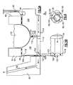
Figure 6 is a schematic isometric representation of an end face of an inner ring having a plurality of radial slots. -
Figure 1 illustrates selected portions of anexample turbine engine 10, such as agas turbine engine 10 used for propulsion. In this example, thegas turbine engine 10 is circumferentially disposed about anengine centerline 12. Thegas turbine engine 10 includes afan section 14, acompressor section 16, acombustion section 18, and aturbine section 20. Thecompressor section 16 and theturbine section 20 includecorresponding blades 22 andvanes 24. Theturbine section 20 includes a high pressure turbine (HPT)section 20a and a low pressure turbine (LPT)section 20b. Further, thecompressor section 16 includes a high pressure compressor (HPC)section 16a and a low pressure compressor (LPC)section 16b. As is known, air compressed in thecompressor section 16 is mixed with fuel and burned in thecombustion section 18 to produce hot gasses that are expanded in theturbine section 20. -
Figure 1 is for illustrative purposes only and is not a limitation on the disclosed examples. Additionally, there are various other types of gas turbine engines, such as geared architecture engines, which could utilize the examples disclosed herein. - The gas turbine-
engine 10 includes abearing system 30 associated with ashaft 32 that rotates about an axis of rotation defined by theengine centerline 12. Theshaft 32 in this example rotates theHPT section 20a of theturbine section 20 and theHPC section 16a of thecompressor section 16. However, it is to be understood that thebearing system 30 may also be applied to other portions of an engine, such as alow pressure shaft 34 for example, or to other types of machines. - Referring to
Figures 2 ,4A-4B , and5A-5B , thebearing system 30 includes a first orinner ring 36 that surrounds the axis of rotation and is coupled in a known manner with theshaft 32, and a second orouter ring 38 that is spaced radially outwards from theinner ring 36 in a direction away from the axis of rotation. Abearing cage 40 is located between theinner ring 36 and theouter ring 38. As shown inFigure 3 , thebearing cage 40 includes a circumferentialouter surface 42, a circumferentialinner surface 44, and a plurality of circumferentially spacedretainer portions 46 that are located between anaxially fore end 48 and an axially trailing oraft end 50. A plurality of bearingelements 52 are supported within the circumferentially spacedretainer portions 46 as known. Thebearing elements 52 may be any of the various types of bearing elements known in the art, including cylindrical, ball, tapered, etc. - As shown in
Figure 4A-4B , theinner ring 36 includes an innercircumferential surface 54 that surrounds the axis of rotation and an outercircumferential surface 56 that is spaced radially outwardly from the innercircumferential surface 54. Afore end surface 58 extends in a radial direction from the innercircumferential surface 54 to the outercircumferential surface 56. Anaft end surface 60 is axially spaced from thefore end surface 58 and extends in a radial direction from the innercircumferential surface 54 to the outercircumferential surface 56. Thus thefore 58 andaft 60 end surfaces define opposing side edges of theinner ring 36. - As shown in
Figure 4A , theinner ring 36 includes araceway 70 that is located between a forward or fore ring land 72 and a trailing or aft ring land 74 that generally protrude radially outwards from theraceway 70. Thebearing elements 52 are located within the retainer portions 46 (Figure 3 ) of thebearing cage 40 and are positioned in theraceway 70 axially between the fore 72 and aft 74 ring lands. - At least one fluid passage or
axial slot 62 is formed in theinner ring 36. Theaxial slot 62 is formed within the innercircumferential surface 54 and extends in a direction along the axis of rotation. Theaxial slot 62 is in fluid communication with a lubrication system 64 (Figure 2 ) of thegas turbine engine 10, which delivers lubricating fluid, such as oil for example, to thebearing elements 52. - At least one
radial side slot 66 is formed in at least one of thefore 58 andaft 60 end surfaces of theinner ring 36. Theradial side slot 66 extends in a radial direction that extends outwardly from the axis of rotation. In the example shown inFigures 4A-4B and5A-5B , theradial side slot 66 is formed within theaft end surface 60. Theradial side slot 66 provides a fluid passage such that lubricating fluid can be dispensed from theaxial slot 62 toward thebearing cage 40. - As discussed above, the
radial side slot 66 is formed in one of thefore 58 andaft 60 end surfaces of theinner ring 36. At least onefluid nozzle 68 is positioned near the other of the fore 58 and aft 60 end surfaces of theinner ring 36. In the example shown, thefluid nozzle 68 is axially spaced from the bearingcage 40 near thefore end surface 58 of theinner ring 36. Thefluid nozzle 68 dispenses lubricating fluid to thebearing elements 52 by directing the fluid toward agap 88 formed between the circumferentialinner surface 44 of the bearingcage 40 and the outercircumferential surface 56 of theinner ring 36. Thefluid nozzle 68 is also in fluid communication with thelubrication system 64 of thegas turbine engine 10. By supplying lubricating fluid through thefluid nozzle 68 and theradial side slot 66 the need for radial holes that extend radially from theaxial slot 62 through the body of the inner ring is eliminated. - In operation, the
lubrication system 64 delivers lubricating fluid to thefluid nozzle 68 and to theaxial slot 62. For example, thelubrication system 64 is a known configuration and includes, for illustratively purposes only, a pump to move the lubricating fluid through thelubrication system 64. The lubricating fluid flows through theaxial slot 62 along the innercircumferential surface 54 of theinner ring 36 and into theradial side slot 66 in theaft end surface 60 of theinner ring 36. Theradial side slot 66 directs the lubricating fluid against the circumferentialinner surface 44 of the bearingcage 40 near theaft end 50 of the bearingcage 40. The lubricating fluid is then directed along the circumferentialinner surface 44 of the bearingcage 40 toward the bearingelements 52. - The
lubrication system 64 may provide more lubricating fluid than required for thebearing system 30. In this regard, the bearingsystem 30 may also include arunner plate 80 adjacent the aft ring land 74 of theinner ring 36. Therunner plate 80 may include at least onefluid passage 82 for receiving surplus lubricating fluid supplied by theaxial slot 62 of theinner ring 36. Thefluid passage 82 serves to collect the surplus fluid and circulates the surplus fluid back into thelubrication system 64. -
Figures 5A-5B show another example of a bearing system. This configuration is similar to that ofFigures 4A-4B ; however theinner ring 36 comprises a split ring. The split ring includes anaft ring piece 100 and afore ring piece 102 that is axially spaced apart from theaft ring piece 100 by agap 104. At least oneradial side slot 106 is formed in anaft end surface 118 of theaft ring piece 100 similar to theradial side slot 66. Additionally, anotherradial side slot 108 is formed at thegap 104. - The
aft ring piece 100 includes afore face 110 that faces anaft face 112 of thefore ring piece 102. The fore 110 and aft 112 faces are separated by thegap 104. Theradial side slot 108 is formed in one of the fore 110 and aft 112 faces. Theradial side slots axial slots 116 formed within the aft 100 and fore 102 ring pieces toward the bearingcage 40 and bearingelements 52 in a manner similar to that described above with regard toFigures 4A-4B . Thefluid nozzle 68 may also be used in a manner similar to that shown inFigures 4A-4B . - In each of the disclosed configurations an
annulus 120 is included to facilitate distribution of the lubricating fluid. Theannulus 120 is formed at a transition between theaxial slot radial side slot annulus 120 is defined by atapered surface 122 that transitions from an inner circumferential surface of the inner ring to theaft end surface tapered surface 122 defines a plane that is obliquely oriented to the axis of rotation. Lubricating fluid is delivered to theannulus 120 via theaxial slots cage 40 via theradial side slots - The axial slots, radial side slots, and annulus cooperate to efficiently dispense lubricating fluid to the bearing elements. The disclosed bearing systems minimize inner ring stress by eliminating the need for radial holes extending through the inner ring and creating high stress concentrations where the hole and bore slot features intersect. The intersection of the side slot(s) with the annulus at the inner ring end face have significantly lower stress concentration levels.
- It should be understood that each inner ring could include a plurality of axial slots and radial side slots. For example,
Figure 6 shows an example that includes a three slot configuration. In this example, theinner ring 36 oraft ring piece 100 includes threeaxial slots radial side slots aft end surface inner ring 36 oraft ring piece 100. The slots in this example are spaced approximate 120 degrees apart from each other; however other spacing configurations could also be used. Also, additional slots can be added or slots can be eliminated depending upon varying specifications. - Although a combination of features is shown in the illustrated examples, not all of them need to be combined to realize the benefits of various embodiments of this disclosure. In other words, a system designed according to an embodiment of this disclosure will not necessarily include all of the features shown in any one of the Figures or all of the portions schematically shown in the Figures. Moreover, selected features of one example embodiment may be combined with selected features of other example embodiments.
- The preceding description is exemplary rather than limiting in nature. Variations and modifications to the disclosed examples may become apparent to those skilled in the art that do not necessarily depart from the essence of .this disclosure. The scope of legal protection given to this disclosure can only be determined by studying the following claims.
Claims (15)
- A bearing system (30) comprising:an inner ring (36) having an inner circumferential surface (54) surrounding an axis of rotation, an outer circumferential surface (56) spaced radially outwardly from said inner circumferential surface (54), a fore end surface (58) extending from said inner circumferential surface (54) to said outer circumferential surface (56), and an aft end surface (60) axially spaced from said fore end surface (58) and extending from said inner circumferential surface (54) to said outer circumferential surface (56);an outer ring (38) spaced radially outwardly of said inner ring (36);a plurality of bearing elements (52) supported by a cage (48) positioned between said inner and said outer rings (36,38); andwherein said inner ring (36) includes at least one axial slot (62;116) extending in a direction along said axis of rotation and wherein at least one of said aft and said fore end surfaces (58,60) includes at least one radial side slot (66;106) extending from said axial slot (62;116) toward said cage (48) such that lubricating fluid is directed to said plurality of bearing elements (52) by said axial slot (62;116) and said radial side slot (66;106).
- The bearing system according to claim 1 wherein said cage (48) defines an inner circumferential cage surface (44) that surrounds said axis of rotation and wherein lubricating fluid is directed by said radial side slot (66;106) toward said inner circumferential cage surface (44) near a corresponding fore or aft outer edge of said cage (48).
- The bearing system according to any preceding claim including an annulus (120) formed at an intersection between said axial slot (62;116) and said radial side slot (66;106) to collect and supply lubricating fluid for distribution to said radial side slot (66;106).
- The bearing system according to claim 3 wherein said annulus (120) is defined by a tapered surface (122) that transitions from said inner circumferential surface (54) to said at least one of said fore and said aft end surfaces (58,60).
- The bearing system according to claim 4 wherein said tapered surface (122) defines a plane that is obliquely orientated relative to said axis of rotation.
- The bearing system according to any preceding claim wherein said inner ring (36) comprises a split ring with an aft ring piece (100) surrounding said axis of rotation and a fore ring piece (102) surrounding said axis of rotation, said fore and aft ring pieces (102,100) being axially separated from each other by a gap (104) such that a fore face (110) of said aft ring piece (100) is spaced apart from and faces an aft face (104) of said fore ring piece (102), and including at least one additional radial slot (108) formed within at least one of said fore and aft faces (110,112) to direct lubricating fluid from said axial slot (62;116) toward said bearing elements (52).
- A turbine engine (10) comprising:a compressor section (16);a combustion section (18) downstream of said compressor section (16);a turbine section (20) downstream of said combustion section (18) wherein at least one of said compressor section (16) and said turbine section (20) includes an engine shaft (32) rotatable about an axis of rotation; anda bearing system including an inner bearing ring (36) coupled with said engine shaft (32), an outer bearing ring (38) spaced radially outwards from said inner bearing ring (36), and a bearing cage (48) positioned between said inner and said outer bearing rings (36,38) to support a plurality of bearing elements (52), and wherein said inner bearing ring (36) includes at least one axial slot (62;116) extending in a direction along said axis of rotation and at least one radial side slot (66;106) formed in at least one of a fore and aft end surface (58,60) of said inner bearing ring (36) to direct lubricating fluid from said axial slot (66;106) to said plurality of bearing elements (52).
- The turbine engine according to claim 10 wherein said inner bearing ring (36) has an inner circumferential surface (54) surrounding said axis of rotation and an outer circumferential surface (56) spaced radially outwardly from said inner circumferential surface (54), and wherein said fore end surface (58) extends from said inner circumferential surface (54) to said outer circumferential surface (56) and said aft end surface (60) is axially spaced from said fore end surface (58) and extends from said inner circumferential surface (54) to said outer circumferential surface (56), and wherein said axial slot (62;116) is formed within said inner circumferential surface (54).
- The turbine engine according to claim 7 or 8 including a tapered surface (102) that transitions from an inner circumferential surface (54) of said inner bearing ring (36) to said at least one of said fore and aft end surfaces (58,60) to form an annulus (100) that collects and supplies lubricating fluid for distribution from said axial slot (62;116) to said radial side slot (66;106).
- The invention according to any preceding claim wherein said at least one radial side slot (66;106) is formed within one of said fore and said aft end surfaces (58,60) and including at least one fluid nozzle (68) positioned near the other of said fore and said aft end surfaces (58,60) to direct lubricating fluid toward said cage (48).
- The invention according to claim 10 wherein said at least one radial side slot (66;106) is formed within said aft end surface (60) to direct lubricating fluid toward an aft edge of said cage (48) and said at least one fluid nozzle (68) is positioned near said fore end surface (58) to direct lubricating fluid toward a fore end of said cage (48).
- A method of providing a lubricating fluid to a bearing system (30) that includes an inner bearing ring (36) surrounding an axis of rotation, an outer bearing ring (38) spaced radially outwards from the inner bearing ring (36), a bearing cage (48) positioned between the inner and the outer bearing rings (36,38), the bearing cage (48) supporting a plurality of bearing elements (52), the method comprising:providing at least one axial slot (62;116) in the inner bearing ring (36) that extends in a direction along the axis of rotation;providing at least one radial side slot (66;106) formed in at least one of a fore and aft end surface (58,60) of the inner bearing ring (36); anddispensing the lubricating into the axial slot (62;116) and directing the lubricating fluid toward the cage (48) via the radial side slot (66;106).
- The method according to claim 12 including forming the at least one radial side slot (66;106) within one of the fore and the aft end surfaces (58,60), providing at least one fluid nozzle (68) positioned near the other of the fore and the an end surfaces (58,60), and dispensing the lubricating fluid from the at least one fluid nozzle (68) in a direction toward a gap between the bearing cage (48) and the inner bearing ring (36) to lubricate the plurality of bearing elements (52).
- The method according to claim 12 or 13 including forming a tapered surface (102) that transitions from an inner circumferential surface (54) of the inner bearing ring (36) to the at least one of the fore and the aft end surfaces (58,60) to form an annulus (120), and collecting lubricating fluid in the annulus (120) for distribution of the lubricating fluid from the axial slot (62;116) to the radial side slot (66;106).
- A bearing system including an inner bearing ring (36) an outer bearing ring (38) spaced radially outwards from said inner bearing ring (36), and a bearing cage (48) positioned between said inner and said outer bearing rings (36,38) to support a plurality of bearing elements (52), and wherein said inner bearing ring (36) includes at least one axial slot (62;116) extending in a direction along said axis of rotation and at least one radial side slot (66;106) formed in at least one of a fore and aft end surface (58,60) of said inner bearing ring (36) to direct lubricating fluid from said axial slot (66;106) to said plurality of bearing elements (52).
Applications Claiming Priority (1)
| Application Number | Priority Date | Filing Date | Title |
|---|---|---|---|
| US12/136,300 US9121303B2 (en) | 2008-06-10 | 2008-06-10 | Bearing system |
Publications (3)
| Publication Number | Publication Date |
|---|---|
| EP2133513A2 true EP2133513A2 (en) | 2009-12-16 |
| EP2133513A3 EP2133513A3 (en) | 2012-11-21 |
| EP2133513B1 EP2133513B1 (en) | 2016-11-02 |
Family
ID=40593843
Family Applications (1)
| Application Number | Title | Priority Date | Filing Date |
|---|---|---|---|
| EP09250804.3A Active EP2133513B1 (en) | 2008-06-10 | 2009-03-23 | Bearing system |
Country Status (2)
| Country | Link |
|---|---|
| US (1) | US9121303B2 (en) |
| EP (1) | EP2133513B1 (en) |
Cited By (4)
| Publication number | Priority date | Publication date | Assignee | Title |
|---|---|---|---|---|
| RU2402686C1 (en) * | 2009-06-17 | 2010-10-27 | Открытое акционерное общество "Научно-производственное объединение "Сатурн" (ОАО "НПО "Сатурн") | Aircraft gas turbine engine oil system |
| RU2480600C1 (en) * | 2011-12-26 | 2013-04-27 | Открытое акционерное общество "Научно-производственное объединение "Сатурн" (ОАО "НПО "Сатурн") | Oil system of power gas turbine plant |
| WO2014130662A1 (en) | 2013-02-20 | 2014-08-28 | United Technologies Corporation | Rolling element bearing configured with a gutter and one or more fluid passages |
| WO2014152167A1 (en) | 2013-03-14 | 2014-09-25 | United Technologies Corporation | Rolling element bearing configured with a channel and one or more fluid passages |
Families Citing this family (7)
| Publication number | Priority date | Publication date | Assignee | Title |
|---|---|---|---|---|
| WO2014200587A2 (en) * | 2013-01-21 | 2014-12-18 | United Technologies Corporation | Air oil cooler airflow augmentation system |
| FR3015599B1 (en) * | 2013-12-23 | 2016-07-22 | Skf Aerospace France | MECHANICAL DEVICE COMPRISING A BEARING AND A LUBRICATION SYSTEM, MACHINE AND METHOD FOR IMPLEMENTING SAID METHOD |
| US10094277B2 (en) | 2014-06-20 | 2018-10-09 | United Technologies Corporation | Gas turbine engine configured for modular assembly/disassembly and method for same |
| CA3057920A1 (en) | 2019-01-15 | 2020-07-15 | Rolls-Royce Corporation | Bearing for use in high speed application |
| US10544834B1 (en) | 2019-01-17 | 2020-01-28 | Rolls-Royce North American Technologies Inc. | Bearing for use in high speed application |
| US11306726B2 (en) | 2019-03-11 | 2022-04-19 | Emerson Climate Technologies, Inc. | Foil bearing assembly and compressor including same |
| RU2729561C1 (en) * | 2019-09-04 | 2020-08-07 | Публичное акционерное общество "ОДК - Уфимское моторостроительное производственное объединение" (ПАО "ОДК-УМПО") | High-pressure rotor support of gas turbine engine |
Family Cites Families (29)
| Publication number | Priority date | Publication date | Assignee | Title |
|---|---|---|---|---|
| GB579252A (en) | 1943-07-30 | 1946-07-29 | Power Jets Ltd | Improvements relating to ball and roller bearings |
| GB821346A (en) | 1955-11-14 | 1959-10-07 | United Aircraft Corp | Lubricating means |
| GB961522A (en) | 1963-01-09 | 1964-06-24 | Rolls Royce | Bearing assembly |
| US3893737A (en) | 1974-04-19 | 1975-07-08 | Marchem Resources Inc | Thrust bearing having lubrication system |
| US3980359A (en) | 1975-05-08 | 1976-09-14 | United Technologies Corporation | Ball bearing |
| US4283096A (en) | 1978-04-21 | 1981-08-11 | United Technologies Corporation | Intershaft bearing |
| JPS5659317U (en) | 1979-10-15 | 1981-05-21 | ||
| US4334720A (en) * | 1980-02-11 | 1982-06-15 | Industrial Tectonics, Inc. | Split-inner-ring ball bearing with lubrication structure |
| US4385788A (en) | 1981-06-26 | 1983-05-31 | United Technologies Corporation | Roller bearing and construction thereof |
| US4428628A (en) | 1981-10-26 | 1984-01-31 | United Technologies Corporation | High speed, durable roller bearing |
| US4400040A (en) | 1981-11-16 | 1983-08-23 | The Timken Company | Tapered roller bearing with improved lubricating means |
| US4463994A (en) | 1982-03-22 | 1984-08-07 | United Technologies Corporation | Split inner race bearing |
| US4721398A (en) | 1985-08-22 | 1988-01-26 | Ishikawajima-Harima Jokogyo Kabushiki Kaisha | Bearing device for rotary machine |
| JPS63231021A (en) * | 1987-03-17 | 1988-09-27 | Nippon Seiko Kk | Lubricating device for rolling bearings |
| US4787757A (en) | 1988-02-08 | 1988-11-29 | The Torrington Company | Bearing construction with a cage provided with lubrication grooves |
| JP2883472B2 (en) | 1991-07-15 | 1999-04-19 | 株式会社東芝 | Circuit breaker malfunction prevention device |
| US5106209A (en) * | 1991-08-07 | 1992-04-21 | General Electric Company | Multi-plane lubricated bearing assembly |
| JP2554634Y2 (en) * | 1991-08-30 | 1997-11-17 | エヌティエヌ株式会社 | Rolling bearing |
| US5201844A (en) | 1991-09-09 | 1993-04-13 | General Electric Company | Rotor and bearing assembly |
| US5183342A (en) | 1991-12-16 | 1993-02-02 | General Electric Company | Lubricated bearing assembly |
| EP0613531A1 (en) | 1992-09-24 | 1994-09-07 | The Torrington Company | Cage for roller bearings |
| DE10015406C1 (en) | 2000-03-28 | 2001-05-10 | Hackewitz Friedrich W Von | Cage for lubricated roller bearing; has long rollers and short rollers with bores, through which bolts pass to connect opposite walls of cage and has depressions to hold ends of long rollers |
| US6464401B1 (en) | 2001-01-26 | 2002-10-15 | United Technologies Corporation | High load capacity bi-directional tapered roller bearing |
| US6511228B2 (en) | 2001-05-08 | 2003-01-28 | Pratt & Whitney Canada Corp. | Oil annulus to circumferentially equalize oil feed to inner race of a bearing |
| US6682222B2 (en) | 2001-08-22 | 2004-01-27 | General Electric Company | Bi-directional oil scoop for bearing lubrication |
| US6758598B2 (en) | 2002-08-23 | 2004-07-06 | Pratt & Whitney Canada Corp. | Integrated oil transfer sleeve and bearing |
| JP2005291445A (en) | 2004-04-02 | 2005-10-20 | Ntn Corp | Tapered roller bearing |
| US20060062504A1 (en) | 2004-09-23 | 2006-03-23 | Wilton Stephen A | Lubricant distribution weir for lubricating moving machine elements |
| FR2880930B1 (en) * | 2005-01-17 | 2007-03-02 | Snecma Moteurs Sa | A BEARING ASSEMBLY COMPRISING A DOUBLE INJECTION OF LUBRICATING LIQUID, AND AERONAUTICAL EQUIPMENT COMPRISING AT LEAST ONE SUCH ASSEMBLY |
-
2008
- 2008-06-10 US US12/136,300 patent/US9121303B2/en active Active
-
2009
- 2009-03-23 EP EP09250804.3A patent/EP2133513B1/en active Active
Cited By (6)
| Publication number | Priority date | Publication date | Assignee | Title |
|---|---|---|---|---|
| RU2402686C1 (en) * | 2009-06-17 | 2010-10-27 | Открытое акционерное общество "Научно-производственное объединение "Сатурн" (ОАО "НПО "Сатурн") | Aircraft gas turbine engine oil system |
| RU2480600C1 (en) * | 2011-12-26 | 2013-04-27 | Открытое акционерное общество "Научно-производственное объединение "Сатурн" (ОАО "НПО "Сатурн") | Oil system of power gas turbine plant |
| WO2014130662A1 (en) | 2013-02-20 | 2014-08-28 | United Technologies Corporation | Rolling element bearing configured with a gutter and one or more fluid passages |
| EP2959177A4 (en) * | 2013-02-20 | 2016-06-15 | United Technologies Corp | ROLLER BEARING CONFIGURED WITH A GUTTER AND ONE OR MORE FLUID PASSAGES |
| WO2014152167A1 (en) | 2013-03-14 | 2014-09-25 | United Technologies Corporation | Rolling element bearing configured with a channel and one or more fluid passages |
| EP2971820A4 (en) * | 2013-03-14 | 2016-07-20 | United Technologies Corp | ROLLING ELEMENT BEARING WITH A CHANNEL AND ONE OR MORE FLUID PASSAGES |
Also Published As
| Publication number | Publication date |
|---|---|
| US9121303B2 (en) | 2015-09-01 |
| EP2133513B1 (en) | 2016-11-02 |
| US20090317029A1 (en) | 2009-12-24 |
| EP2133513A3 (en) | 2012-11-21 |
Similar Documents
| Publication | Publication Date | Title |
|---|---|---|
| EP2133513B1 (en) | Bearing system | |
| EP2031261B1 (en) | System for supplying oil from an oil source to a bearing assembly | |
| US6409464B1 (en) | Methods and apparatus for supplying oil to bearing assemblies | |
| US7296398B2 (en) | Counter-rotating turbine engine and method of assembling same | |
| EP2058541B1 (en) | Method and apparatus for fan shaft bearing lubrication | |
| EP2657463B1 (en) | Oil scoop manifold | |
| US7458202B2 (en) | Lubrication system for a counter-rotating turbine engine and method of assembling same | |
| US10767753B2 (en) | Rolling element cage for geared turbofan | |
| US10352456B2 (en) | Axial scoop seal plate | |
| EP2766621B1 (en) | Dynamically-lubricated bearing and method of dynamically lubricating a bearing | |
| EP2407640A2 (en) | Integral lubrication tube and nozzle combination | |
| EP2426368B1 (en) | Bearing system and method for lubrication | |
| US8770928B2 (en) | Air cycle machine seal plate and seal land | |
| EP3628881B1 (en) | Inner ring for a bearing and method for proportioning lubricant to a bearing | |
| EP3699447B1 (en) | Bearing for use in high speed application | |
| US10876578B2 (en) | Bearing assembly with inner rings and method of alignment | |
| EP3683465B1 (en) | Bearing for use in high speed application | |
| US12571330B2 (en) | Oil nozzle for bearing chamber | |
| US20260049564A1 (en) | Annular oil distributor for bearing chamber |
Legal Events
| Date | Code | Title | Description |
|---|---|---|---|
| PUAI | Public reference made under article 153(3) epc to a published international application that has entered the european phase |
Free format text: ORIGINAL CODE: 0009012 |
|
| AK | Designated contracting states |
Kind code of ref document: A2 Designated state(s): AT BE BG CH CY CZ DE DK EE ES FI FR GB GR HR HU IE IS IT LI LT LU LV MC MK MT NL NO PL PT RO SE SI SK TR |
|
| AX | Request for extension of the european patent |
Extension state: AL BA RS |
|
| PUAL | Search report despatched |
Free format text: ORIGINAL CODE: 0009013 |
|
| AK | Designated contracting states |
Kind code of ref document: A3 Designated state(s): AT BE BG CH CY CZ DE DK EE ES FI FR GB GR HR HU IE IS IT LI LT LU LV MC MK MT NL NO PL PT RO SE SI SK TR |
|
| AX | Request for extension of the european patent |
Extension state: AL BA RS |
|
| RIC1 | Information provided on ipc code assigned before grant |
Ipc: F01D 25/16 20060101ALI20121017BHEP Ipc: F01D 5/00 20060101AFI20121017BHEP Ipc: F01D 25/18 20060101ALI20121017BHEP |
|
| 17P | Request for examination filed |
Effective date: 20130521 |
|
| AKX | Designation fees paid |
Designated state(s): DE GB |
|
| 17Q | First examination report despatched |
Effective date: 20160321 |
|
| GRAP | Despatch of communication of intention to grant a patent |
Free format text: ORIGINAL CODE: EPIDOSNIGR1 |
|
| INTG | Intention to grant announced |
Effective date: 20160621 |
|
| GRAS | Grant fee paid |
Free format text: ORIGINAL CODE: EPIDOSNIGR3 |
|
| GRAA | (expected) grant |
Free format text: ORIGINAL CODE: 0009210 |
|
| RAP1 | Party data changed (applicant data changed or rights of an application transferred) |
Owner name: UNITED TECHNOLOGIES CORPORATION |
|
| AK | Designated contracting states |
Kind code of ref document: B1 Designated state(s): DE GB |
|
| REG | Reference to a national code |
Ref country code: GB Ref legal event code: FG4D |
|
| REG | Reference to a national code |
Ref country code: DE Ref legal event code: R096 Ref document number: 602009042055 Country of ref document: DE |
|
| REG | Reference to a national code |
Ref country code: DE Ref legal event code: R082 Ref document number: 602009042055 Country of ref document: DE Representative=s name: SCHMITT-NILSON SCHRAUD WAIBEL WOHLFROM PATENTA, DE |
|
| REG | Reference to a national code |
Ref country code: DE Ref legal event code: R097 Ref document number: 602009042055 Country of ref document: DE |
|
| PLBE | No opposition filed within time limit |
Free format text: ORIGINAL CODE: 0009261 |
|
| STAA | Information on the status of an ep patent application or granted ep patent |
Free format text: STATUS: NO OPPOSITION FILED WITHIN TIME LIMIT |
|
| 26N | No opposition filed |
Effective date: 20170803 |
|
| REG | Reference to a national code |
Ref country code: DE Ref legal event code: R081 Ref document number: 602009042055 Country of ref document: DE Owner name: RAYTHEON TECHNOLOGIES CORPORATION (N.D.GES.D.S, US Free format text: FORMER OWNER: UNITED TECHNOLOGIES CORPORATION, FARMINGTON, CONN., US Ref country code: DE Ref legal event code: R081 Ref document number: 602009042055 Country of ref document: DE Owner name: RTX CORPORATION (N.D.GES.D. STAATES DELAWARE),, US Free format text: FORMER OWNER: UNITED TECHNOLOGIES CORPORATION, FARMINGTON, CONN., US |
|
| P01 | Opt-out of the competence of the unified patent court (upc) registered |
Effective date: 20230519 |
|
| REG | Reference to a national code |
Ref country code: DE Ref legal event code: R081 Ref document number: 602009042055 Country of ref document: DE Owner name: RTX CORPORATION (N.D.GES.D. STAATES DELAWARE),, US Free format text: FORMER OWNER: RAYTHEON TECHNOLOGIES CORPORATION (N.D.GES.D.STAATES DELAWARE), ARLINGTON, VA, US |
|
| PGFP | Annual fee paid to national office [announced via postgrant information from national office to epo] |
Ref country code: GB Payment date: 20260219 Year of fee payment: 18 |
|
| PGFP | Annual fee paid to national office [announced via postgrant information from national office to epo] |
Ref country code: DE Payment date: 20260219 Year of fee payment: 18 |