EP2133269A2 - Engine mounting arrangement - Google Patents
Engine mounting arrangement Download PDFInfo
- Publication number
- EP2133269A2 EP2133269A2 EP09251293A EP09251293A EP2133269A2 EP 2133269 A2 EP2133269 A2 EP 2133269A2 EP 09251293 A EP09251293 A EP 09251293A EP 09251293 A EP09251293 A EP 09251293A EP 2133269 A2 EP2133269 A2 EP 2133269A2
- Authority
- EP
- European Patent Office
- Prior art keywords
- engine
- mounting arrangement
- thrust
- primary
- engine mounting
- Prior art date
- Legal status (The legal status is an assumption and is not a legal conclusion. Google has not performed a legal analysis and makes no representation as to the accuracy of the status listed.)
- Granted
Links
Images


Classifications
-
- B—PERFORMING OPERATIONS; TRANSPORTING
- B64—AIRCRAFT; AVIATION; COSMONAUTICS
- B64D—EQUIPMENT FOR FITTING IN OR TO AIRCRAFT; FLIGHT SUITS; PARACHUTES; ARRANGEMENT OR MOUNTING OF POWER PLANTS OR PROPULSION TRANSMISSIONS IN AIRCRAFT
- B64D27/00—Arrangement or mounting of power plants in aircraft; Aircraft characterised by the type or position of power plants
- B64D27/40—Arrangements for mounting power plants in aircraft
-
- B—PERFORMING OPERATIONS; TRANSPORTING
- B64—AIRCRAFT; AVIATION; COSMONAUTICS
- B64D—EQUIPMENT FOR FITTING IN OR TO AIRCRAFT; FLIGHT SUITS; PARACHUTES; ARRANGEMENT OR MOUNTING OF POWER PLANTS OR PROPULSION TRANSMISSIONS IN AIRCRAFT
- B64D27/00—Arrangement or mounting of power plants in aircraft; Aircraft characterised by the type or position of power plants
- B64D27/40—Arrangements for mounting power plants in aircraft
- B64D27/406—Suspension arrangements specially adapted for supporting thrust loads, e.g. thrust links
-
- Y—GENERAL TAGGING OF NEW TECHNOLOGICAL DEVELOPMENTS; GENERAL TAGGING OF CROSS-SECTIONAL TECHNOLOGIES SPANNING OVER SEVERAL SECTIONS OF THE IPC; TECHNICAL SUBJECTS COVERED BY FORMER USPC CROSS-REFERENCE ART COLLECTIONS [XRACs] AND DIGESTS
- Y02—TECHNOLOGIES OR APPLICATIONS FOR MITIGATION OR ADAPTATION AGAINST CLIMATE CHANGE
- Y02T—CLIMATE CHANGE MITIGATION TECHNOLOGIES RELATED TO TRANSPORTATION
- Y02T50/00—Aeronautics or air transport
- Y02T50/40—Weight reduction
Definitions
- the present invention relates to an engine mounting arrangement and is particularly concerned with a mounting arrangement for attaching an aircraft engine to an aircraft pylon.
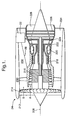
- a gas turbine engine 210 is shown in schematic section in Figure 1 and comprises a main rotational axis 208, an air intake 212 and a propulsive fan 214 that generates two airflows A and B.
- the gas turbine engine 210 comprises, in axial flow A, an intermediate pressure compressor 216, a high pressure compressor 218, a combustor 220, a high pressure turbine 222, an intermediate pressure turbine 224, a low pressure turbine 226 and an exhaust nozzle 228.
- a nacelle 230 surrounds the gas turbine engine 210 and defines, in axial flow B, a bypass duct 232 between the air intake 212 and an exhaust nozzle 234.
- a rear engine mounting arrangement 22 (rear in the sense of airflows A and B) is shown in the vicinity of the turbines 222, 224, 226. Thrust struts 26 interconnect the rear engine mounting arrangement 22 with a forward section of the engine 210.
- the rear engine mounting arrangement 22 is connectable to an aircraft pylon (not shown).
- the rear engine mounting arrangement 22 is located at a radially outer extent of the engine 210, preferably at top dead centre. For the purposes of the following description, this will be taken to be vertically above the engine although it should be understood that the engine 210 may be hung at an angle to the vertical.
- FIG. 2 which shows in schematic perspective view a conventional rear engine mounting arrangement 22 for mounting an engine 210 on an aircraft, whether under a wing or against a fuselage. It is conventional to provide each of a front and a rear mounting arrangement. Where the engine is a gas turbine engine 210, the front mounting is generally provided in the vicinity of the fan 214 or compressors 216, 218 and the rear mounting is generally provided in the vicinity of the turbines 222, 224, 226. However, other arrangements are possible.
- the rear mounting arrangement 22 comprises means for connection of thrust struts 26 to transfer the thrust generated by the engine 210 through the mounting arrangement 22 and the pylon to the aircraft.
- a forward engine mounting arrangement (not shown) is also provided, preferably in the vicinity of the compressors of a gas turbine engine 210 to transfer engine side and vertical loads but not thrust loads.
- a conventional rear engine mounting arrangement 22 is shown in Figure 2 in highly schematic form.
- the arrangement comprises a mount block 10 that includes means to attach it both to the aircraft pylon and to the engine 210. It further comprises an integral clevis arrangement 12 protruding forward from the main body of the mount block 10.
- the clevis arrangement 12 has a main thrust connection 14, which is connectable to a thrust yoke 16 by a pivot pin or similar.
- the yoke 16 is connected to the thrust struts 26 ( Figure 1 ) at connection points 18 by pin and clevis arrangements.
- the propulsive thrust loads are transferred from the engine through the thrust struts 26, yoke 16, main thrust connection 14 and mount block 10 and from thence into the pylon of the aircraft.
- the clevis arrangement 12 further comprises a pair of catcher clevises 20 located on either side of the main thrust connection 14. These comprise a clearance around their respective pivot pins so that in normal operation of the engine mounting arrangement 22 no thrust loads are transferred through the catcher clevises 20 and pins. In the event of a failure of the main clevis 14, the clearance is taken up around one or both of the catcher pivot pins and one or both of the catchers 20 transfer the thrust loads in preference or addition to the main thrust connection 14.
- the present invention seeks to provide a novel rear engine mounting arrangement that seeks to address the aforementioned problems.
- the present invention provides an engine mounting arrangement comprising thrust struts, a balance yoke, and primary and secondary mount blocks, the thrust struts being connected to the balance yoke and the primary mount block comprising at least one thrust load connection connectable to the balance yoke for transferring thrust loads from an engine during normal operation of the engine mounting arrangement, characterised in that that the secondary mount block is connected to the balance yoke via at least one thrust load catcher connection, the at least one thrust load catcher connection being arranged to be unloaded during normal operation of the engine mounting arrangement and to transfer the thrust loads from the engine in the event of a failure condition of the primary mount block.
- the primary and secondary mount blocks are secured together.
- the primary mount block comprises a single thrust load connection.
- the arrangement further comprises at least one engine attachment link, each of the primary and secondary mount blocks having means of connection to the at least one engine attachment link. More preferably at least part of the means of connection of the primary and secondary mount blocks connects to a common part of the at least one engine attachment link.
- the thrust load connection comprises a clevis arrangement having two lugs.
- it comprises a single lug.
- the thrust load catcher connection comprises a clevis arrangement having two lugs.
- it comprises a single lug.
- the at least one thrust load catcher connection defines a clearance with respect to the balance yoke so that no load passes therethrough during normal operation of the engine mounting arrangement.
- FIG. 3 An exemplary embodiment of the rear engine mounting arrangement 22 of the present invention is shown in Figure 3 .
- the arrangement 22 comprises a primary mount block 30 and a secondary mount block 32 secured together.
- the engine attachment links 34, 36, 38 are connected to points on the engine 210 by a clevis and pin arrangement.
- the port side attachment link 38 is generally longitudinal and comprises an aperture 40 containing a spherical bearing which, in use, sits within a complementary clevis fixed at a suitable location on a casing of the engine.
- a pin 41 is inserted through the aperture 40 in the port side attachment link 38 (as shown by interrupted lines) and a complementary aperture in the clevis to connect them together.
- a similar arrangement is provided for each of the starboard side 34 and central 36 attachment links. The arrangement of connection of the engine attachment links 34, 36, 38 to the primary and secondary mount blocks 30, 32 will be described below.
- An advantage of providing a clevis and pin arrangement between the engine 210 and the rear engine mounting arrangement 22 is that differential thermal expansion does not place undue stress or strain on any of the components as some relative movement is permitted in at least one plane.
- other arrangements of connecting the engine attachment links 34, 36, 38 to the engine 210 are considered to fall within the scope of the present invention.
- the primary mount block 30 of the rear mounting arrangement 22 of the present invention is now described with reference to Figure 3 (showing both the primary and secondary mount blocks 30, 32) and Figure 4 (showing just the primary mount block 30).
- the primary mount block 30 presents a substantially rectangular profile and comprises a main portion 46 and a central portion 44 with a tongue 42 protruding forwardly from the central portion 44 of the block 30.
- the central portion 44 of the primary mount block 30, extending rearwardly of the tongue 42, is raised above the otherwise substantially planar main portion 46.
- the central portion 44 may be substantially planar with the main portion 46.
- the central portion 44 may be separate to or integral with the main portion 46 of the primary mount block 30; in this embodiment the central 44 and main 46 portions are integral.
- the primary mount block 30 defines a plurality of apertures 48 therethrough (of which only some are indicated for clarity) that receive, in use, attachment bolts 50 (only two of which are shown) to connect the primary mount block 30 to the aircraft pylon and to the secondary mount block 32.
- the apertures 48 are located in an equally spaced row parallel to each lateral edge of the primary mount block 30.
- the number of apertures 48 required will depend on the geometries and forces involved in mounting a particular engine 210 to a particular pylon. However, in the typical rear engine mounting arrangement 22 shown, there are four apertures 48 provided parallel to each lateral edge of the primary mount block 30 each arranged to receive an attachment bolt 50.
- the tongue 42 is preferably provided in the form of a clevis having upper 52 and lower 54 lugs, which define apertures 56 therethrough, the apertures 56 are aligned to receive a pivot pin (not shown) through the plane of the lugs 52, 54.
- a thrust strut balance yoke 58 is located symmetrically within the clevis of the tongue 42 and comprises an aperture 60 therethrough that aligns with the apertures 56 through the tongue 42. The pivot pin therefore connects the thrust strut balance yoke 58 within the tongue 42.
- a clearance is provided between the thrust strut balance yoke 58 and the rear of the clevis formed by the tongue 42, in the plane of the thrust strut balance yoke 58 and the tongue 42, to enable the thrust strut balance yoke 58 to pivot around the pivot pin through apertures 56, 60 to balance the loads from the thrust struts 26.
- the two thrust struts 26 are connected to the lateral ends 62 of the thrust strut balance yoke 58, or more preferably to forwardly extending protrusions thereof, by pins retained within spherical bearings or any other suitable means.
- the connection is by means of a clevis arrangement to allow the thrust struts 26 and the balance yoke 58 to pivot relative to each other to compensate for variations in the thrust transmitted by each of the thrust struts 26.
- the clevis arrangement comprises a pair of lugs on one of the thrust strut 26 and the yoke 58, and a single lug on the other that sits between the pair of lugs.
- a pivot pin is inserted through aligned apertures, with a spherical bearing therein, to secure the thrust strut 26 and yoke 58 pivotably together.
- the primary mount block 30 also comprises a recess or aperture 64 in an upper surface (radially outer surface) of the central portion 44 to receive, in use, a thrust shear pin from the aircraft pylon.
- the recess 64 may be positioned at any suitable location or there may be more than one recess 64 provided symmetrically across the primary mount block 30 for an equivalent number of shear pins.
- the secondary mount block 32 can be more clearly seen in Figure 5 and Figure 6 in two perspective views, one from above and one from below.
- the upper surface 66 of the secondary mount block 32 is substantially planar and arranged to abut the lower surface (radially inner surface) of the primary mount block 30.
- Additional apertures or recesses 70 may be provided inwardly of the lateral edges of the secondary mount block 32 to receive additional fixings 72 ( Figure 3 ) to secure the two mount blocks 30, 32 together.
- the secondary mount block 32 includes a cutaway section 74 in its forward edge to accommodate, in use, the tongue 42 of the primary mount block 30.
- Each catcher clevis 76 comprises an aperture 78 through its lugs.
- the catcher clevises 76 are arranged to receive, in use, the balance yoke 58 between its lugs.
- a pivot pin (not shown) is inserted through each aperture arrangement to hold the components in pivotable relation.
- the apertures 78 through the catcher clevises 76 are provided with a clearance gap around their pivot pins so that no load is transferred through them during normal operation of the rear engine mounting arrangement 22.
- the upper (radially outer) surface 66 of the secondary mount block 32 also comprises a pair of raised sections 80 at the lateral edges of the secondary mount block 32 arranged to sit within corresponding cutaway portions 82 in the lateral edges of the primary mount block 30.
- These raised sections 80 each have a recess or aperture 84 to receive, in use, a secondary shear pin from the pylon (not shown). These shear pins become loaded in the event of the failure of a component in the primary load path and substitution of the alternative load path but are not loaded during normal operation of the rear engine mounting arrangement 22 since no load is transferred through the secondary mount block 32.
- Alternative embodiments of the present invention do not comprise the raised sections 80 in the secondary mount block 32 and complementary recesses 84 in the primary mount block 30.
- the primary and secondary mount blocks 30, 32 simply abut.
- the primary mount block 30 consists of the central portion 44 but not the main portion 46.
- part of the upper surface 66 of the secondary mount block 32 is directly exposed to the pylon rather than abutting the primary mount block 30.
- the upper surface 66 may be raised over substantially its whole surface instead of having smaller raised sections 80 as illustrated in Figure 5 .
- the rear edge of the secondary mount block 32 may be profiled in such a way that the axial length of the secondary mount block 32 is greater towards the lateral edges than at its centre. This provides a reduction in the weight of the component without compromising its strength.
- Figure 4 shows a clevis 92 defined between primary forward and rear walls 94, 96 extending from the lower surface of the primary mount block 30 towards the engine 210 (not shown).
- a clevis 86 is defined between secondary forward and rear walls 88, 90 extending from the lower surface of the secondary mount block 32.
- the secondary forward and rear walls 88, 90 are spaced to receive the primary forward and rear walls 94, 96 slotted between them to form a double clevis.
- the profile of each of the forward and rear walls 88, 90, 94, 96 is the same.
- the primary forward and rear walls 94, 96 define three apertures 98, 100, 102 which are arranged to receive a pivot pin (not shown) through each.
- the secondary forward and rear walls 88, 90 are laterally wider than the primary forward and rear walls 94, 96 and define five apertures 104, 106, 108, 110, 112.
- the central three apertures 106, 108, 110 align respectively with the apertures 98, 100, 102 in the primary forward and rear walls 94, 96.
- the engine attachment links 34, 36, 38 each have one or two apertures through their upper ends which, when the links 34, 36, 38 are positioned in the double clevis formed by the primary forward and rear walls 94, 96 and secondary forward and rear walls 88, 90, align with the apertures 98, 100, 102, 104, 106, 108, 110, 112. Pivot pins are inserted through each aperture or aperture set: 104; 106, 98; 108, 100; 110, 102; 112.
- pivot pins interconnect the engine attachment links 34, 36, 38 within the double clevis formed by the primary forward and rear walls 94, 96 and secondary forward and rear walls 88, 90 so that the engine loads can be transferred from the engine 210, through the links 34, 36, 38, via the primary and secondary mount blocks 30, 32 and thence into the aircraft pylon.
- the engine attachment links 34, 36, 38 can take any suitable form as known in the art that provide redundancy for all single pivot pin, link or clevis failures or for failure of any adjacent pair. This redundancy relies on the connections to the secondary mount block 32 only. The connections to the primary mount block 30 provide additional redundancy for complete failure of the secondary mount block 32.
- the connection arrangement also provides a quick and simple method of detecting a failure case without requiring removal of the rear engine mounting arrangement 22. If the pivot pins located through the aperture pairs 106, 98; 108, 100 are able to rotate freely (unloaded) there is no failure. If one or both of these pivot pins is loaded, and therefore unable to rotate freely, there has been a failure and the rear engine mounting arrangement 22 should be removed, dismantled and repaired or replaced.
- connections have primarily been described as clevis arrangements comprising a pair of lugs on one component and a single lug forming part of the other component to seat between the pair of lugs.
- the connections could equally be formed by providing the pair of lugs on the other component, or by providing a pair of lugs on each component forming an interleaving connection.
- a single lug could be provided on each component. This reduces the weight of the components but removes some redundancy from the system.
- the primary rear wall 96 could be omitted so that the apertures 98, 100 and 102 are defined through only the primary forward wall 94, or vice versa.
- the catcher clevises 76 could comprise single lugs to be secured via pivot pins to the balance yoke 58 or the tongue 42 could comprise a single lug to be secured to the balance yoke 58.
- engine mounting arrangement of the present invention has been described as a rear mounting arrangement, it could alternatively be a front engine mounting arrangement.
- the central portion 44 of the primary mount block 30 may be integral with the main portion 46 thereof. Alternatively it may comprise a separate component with suitable connection therebetween. Preferably the bolts 72 could simultaneously secure the central and main portions 44, 46 of the primary mount block 30 to each other and to the secondary mount block 32.
- catcher clevises 76 are provided to transfer the thrust loads from the engine 210 via the balance yoke 58 in the event of a failure of a component in the normal load path. This provides the additional advantage that the thrust loads continue to be balanced by minor movements of the balance yoke 58.
- other arrangements comprising a single, or more than two, catcher clevises 76 are contemplated within the scope of the present invention.
- attachment apertures 48, 68 and complementary bolts 50 are described above, more or fewer apertures and bolts may be more appropriate in connecting other specific engines to specific aircraft pylons.
Landscapes
- Engineering & Computer Science (AREA)
- Aviation & Aerospace Engineering (AREA)
- Vibration Prevention Devices (AREA)
- Structures Of Non-Positive Displacement Pumps (AREA)
Abstract
Description
- The present invention relates to an engine mounting arrangement and is particularly concerned with a mounting arrangement for attaching an aircraft engine to an aircraft pylon.
- A gas turbine engine 210 is shown in schematic section in
Figure 1 and comprises a mainrotational axis 208, anair intake 212 and apropulsive fan 214 that generates two airflows A and B. The gas turbine engine 210 comprises, in axial flow A, anintermediate pressure compressor 216, ahigh pressure compressor 218, acombustor 220, ahigh pressure turbine 222, anintermediate pressure turbine 224, alow pressure turbine 226 and anexhaust nozzle 228. Anacelle 230 surrounds the gas turbine engine 210 and defines, in axial flow B, abypass duct 232 between theair intake 212 and anexhaust nozzle 234. A rear engine mounting arrangement 22 (rear in the sense of airflows A and B) is shown in the vicinity of theturbines Thrust struts 26 interconnect the rearengine mounting arrangement 22 with a forward section of the engine 210. The rearengine mounting arrangement 22 is connectable to an aircraft pylon (not shown). The rearengine mounting arrangement 22 is located at a radially outer extent of the engine 210, preferably at top dead centre. For the purposes of the following description, this will be taken to be vertically above the engine although it should be understood that the engine 210 may be hung at an angle to the vertical. - Referring to
Figure 2 , which shows in schematic perspective view a conventional rearengine mounting arrangement 22 for mounting an engine 210 on an aircraft, whether under a wing or against a fuselage. It is conventional to provide each of a front and a rear mounting arrangement. Where the engine is a gas turbine engine 210, the front mounting is generally provided in the vicinity of thefan 214 orcompressors turbines rear mounting arrangement 22 comprises means for connection ofthrust struts 26 to transfer the thrust generated by the engine 210 through themounting arrangement 22 and the pylon to the aircraft. Typically a forward engine mounting arrangement (not shown) is also provided, preferably in the vicinity of the compressors of a gas turbine engine 210 to transfer engine side and vertical loads but not thrust loads. - A conventional rear
engine mounting arrangement 22 is shown inFigure 2 in highly schematic form. The arrangement comprises amount block 10 that includes means to attach it both to the aircraft pylon and to the engine 210. It further comprises anintegral clevis arrangement 12 protruding forward from the main body of themount block 10. Theclevis arrangement 12 has amain thrust connection 14, which is connectable to athrust yoke 16 by a pivot pin or similar. Theyoke 16 is connected to the thrust struts 26 (Figure 1 ) atconnection points 18 by pin and clevis arrangements. Thus the propulsive thrust loads are transferred from the engine through thethrust struts 26,yoke 16,main thrust connection 14 andmount block 10 and from thence into the pylon of the aircraft. - The
clevis arrangement 12 further comprises a pair ofcatcher clevises 20 located on either side of themain thrust connection 14. These comprise a clearance around their respective pivot pins so that in normal operation of theengine mounting arrangement 22 no thrust loads are transferred through thecatcher clevises 20 and pins. In the event of a failure of themain clevis 14, the clearance is taken up around one or both of the catcher pivot pins and one or both of thecatchers 20 transfer the thrust loads in preference or addition to themain thrust connection 14. - One disadvantage of this engine mounting arrangement is that a failure crack emanating from either the engine attachment means or the main
thrust connection clevis 14 can propagate to fail an adjacent clevis without detection. Whilst this can be certified by crack growth and propagation analysis, this is an unsatisfactory solution since it requires heavier and stronger materials to ensure the minimal crack growth properties required. - Thus it is desirable to have an engine mounting arrangement that has a failure load path that does not rely on crack growth and propagation analysis.
- The present invention seeks to provide a novel rear engine mounting arrangement that seeks to address the aforementioned problems.
- Accordingly the present invention provides an engine mounting arrangement comprising thrust struts, a balance yoke, and primary and secondary mount blocks, the thrust struts being connected to the balance yoke and the primary mount block comprising at least one thrust load connection connectable to the balance yoke for transferring thrust loads from an engine during normal operation of the engine mounting arrangement, characterised in that that the secondary mount block is connected to the balance yoke via at least one thrust load catcher connection, the at least one thrust load catcher connection being arranged to be unloaded during normal operation of the engine mounting arrangement and to transfer the thrust loads from the engine in the event of a failure condition of the primary mount block.
- Preferably the primary and secondary mount blocks are secured together.
- Preferably the primary mount block comprises a single thrust load connection.
- Preferably the arrangement further comprises at least one engine attachment link, each of the primary and secondary mount blocks having means of connection to the at least one engine attachment link. More preferably at least part of the means of connection of the primary and secondary mount blocks connects to a common part of the at least one engine attachment link.
- Preferably the thrust load connection comprises a clevis arrangement having two lugs. Alternatively it comprises a single lug.
- Preferably the thrust load catcher connection comprises a clevis arrangement having two lugs. Alternatively it comprises a single lug.
- More preferably there are two thrust load catcher connections arranged to transfer the thrust loads from the engine, either separately or in unison during a failure condition of the primary mount block.
- Preferably the at least one thrust load catcher connection defines a clearance with respect to the balance yoke so that no load passes therethrough during normal operation of the engine mounting arrangement.
- The present invention will be more fully described by way of example with reference to the accompanying drawings, in which:
-
Figure 1 is a sectional side view of a gas turbine engine having a conventional rear engine mounting arrangement. -
Figure 2 is a highly schematic perspective view of an engine mounting arrangement according to the prior art as described above. -
Figure 3 is a perspective view of a rear engine mounting arrangement according to the present invention. -
Figure 4 is a perspective view of the primary mount block of the rear engine mounting arrangement according to the present invention. -
Figures 5 and6 are a pair of perspective views of the secondary mount block of the rear engine mounting arrangement according to the present invention. - An exemplary embodiment of the rear
engine mounting arrangement 22 of the present invention is shown inFigure 3 . Thearrangement 22 comprises aprimary mount block 30 and asecondary mount block 32 secured together. There are three engine attachment links, 34, 36, 38, which interconnect with corresponding attachment points on the engine 210 to one or both of the primary andsecondary mount blocks engine attachment links Figure 3 , the portside attachment link 38 is generally longitudinal and comprises anaperture 40 containing a spherical bearing which, in use, sits within a complementary clevis fixed at a suitable location on a casing of the engine. Apin 41 is inserted through theaperture 40 in the port side attachment link 38 (as shown by interrupted lines) and a complementary aperture in the clevis to connect them together. A similar arrangement is provided for each of thestarboard side 34 and central 36 attachment links. The arrangement of connection of theengine attachment links secondary mount blocks - An advantage of providing a clevis and pin arrangement between the engine 210 and the rear
engine mounting arrangement 22 is that differential thermal expansion does not place undue stress or strain on any of the components as some relative movement is permitted in at least one plane. However, other arrangements of connecting theengine attachment links - The
primary mount block 30 of therear mounting arrangement 22 of the present invention is now described with reference toFigure 3 (showing both the primary andsecondary mount blocks 30, 32) andFigure 4 (showing just the primary mount block 30). Theprimary mount block 30 presents a substantially rectangular profile and comprises amain portion 46 and acentral portion 44 with atongue 42 protruding forwardly from thecentral portion 44 of theblock 30. Thecentral portion 44 of theprimary mount block 30, extending rearwardly of thetongue 42, is raised above the otherwise substantially planarmain portion 46. In other embodiments thecentral portion 44 may be substantially planar with themain portion 46. Thecentral portion 44 may be separate to or integral with themain portion 46 of theprimary mount block 30; in this embodiment the central 44 and main 46 portions are integral. Theprimary mount block 30 defines a plurality ofapertures 48 therethrough (of which only some are indicated for clarity) that receive, in use, attachment bolts 50 (only two of which are shown) to connect theprimary mount block 30 to the aircraft pylon and to thesecondary mount block 32. Preferably theapertures 48 are located in an equally spaced row parallel to each lateral edge of theprimary mount block 30. The number ofapertures 48 required will depend on the geometries and forces involved in mounting a particular engine 210 to a particular pylon. However, in the typical rearengine mounting arrangement 22 shown, there are fourapertures 48 provided parallel to each lateral edge of theprimary mount block 30 each arranged to receive anattachment bolt 50. - The
tongue 42 is preferably provided in the form of a clevis having upper 52 and lower 54 lugs, which defineapertures 56 therethrough, theapertures 56 are aligned to receive a pivot pin (not shown) through the plane of thelugs strut balance yoke 58 is located symmetrically within the clevis of thetongue 42 and comprises anaperture 60 therethrough that aligns with theapertures 56 through thetongue 42. The pivot pin therefore connects the thrust strutbalance yoke 58 within thetongue 42. A clearance is provided between the thruststrut balance yoke 58 and the rear of the clevis formed by thetongue 42, in the plane of the thrust strutbalance yoke 58 and thetongue 42, to enable the thrust strutbalance yoke 58 to pivot around the pivot pin throughapertures - The two thrust struts 26 are connected to the lateral ends 62 of the thrust strut
balance yoke 58, or more preferably to forwardly extending protrusions thereof, by pins retained within spherical bearings or any other suitable means. Preferably, the connection is by means of a clevis arrangement to allow the thrust struts 26 and thebalance yoke 58 to pivot relative to each other to compensate for variations in the thrust transmitted by each of the thrust struts 26. For eachthrust strut 26, the clevis arrangement comprises a pair of lugs on one of thethrust strut 26 and theyoke 58, and a single lug on the other that sits between the pair of lugs. A pivot pin is inserted through aligned apertures, with a spherical bearing therein, to secure thethrust strut 26 andyoke 58 pivotably together. - The
primary mount block 30 also comprises a recess oraperture 64 in an upper surface (radially outer surface) of thecentral portion 44 to receive, in use, a thrust shear pin from the aircraft pylon. Therecess 64 may be positioned at any suitable location or there may be more than onerecess 64 provided symmetrically across theprimary mount block 30 for an equivalent number of shear pins. - The
secondary mount block 32 can be more clearly seen inFigure 5 andFigure 6 in two perspective views, one from above and one from below. Theupper surface 66 of thesecondary mount block 32 is substantially planar and arranged to abut the lower surface (radially inner surface) of theprimary mount block 30. There are apertures 68 (only some are indicated for clarity) provided through thesecondary mount block 32 in an equally spaced row parallel to each lateral edge of thesecondary mount block 32. Theseapertures 68 align with theapertures 48 in theprimary mount block 30 to receive theattachment bolts 50 to secure the mount blocks 30, 32 together and thence to the pylon. Additional apertures or recesses 70 may be provided inwardly of the lateral edges of thesecondary mount block 32 to receive additional fixings 72 (Figure 3 ) to secure the two mount blocks 30, 32 together. - The
secondary mount block 32 includes acutaway section 74 in its forward edge to accommodate, in use, thetongue 42 of theprimary mount block 30. On either lateral side of thiscutaway section 74 there arecatcher clevises 76 comprising a pair of lugs as is well known for a clevis. Eachcatcher clevis 76 comprises anaperture 78 through its lugs. The catcher clevises 76 are arranged to receive, in use, thebalance yoke 58 between its lugs. There are apertures provided in thebalance yoke 58 to align with theapertures 78 in thecatcher clevises 76. A pivot pin (not shown) is inserted through each aperture arrangement to hold the components in pivotable relation. Theapertures 78 through thecatcher clevises 76 are provided with a clearance gap around their pivot pins so that no load is transferred through them during normal operation of the rearengine mounting arrangement 22. - In the event of a failure of the
tongue 42 of theprimary mount block 30, the clearance around the pivot pins through thecatcher clevises 76 is taken up and engine loads are transferred from thebalance yoke 58, through the catcher clevises 76 and thence to the aircraft pylon in the alternative load path. - The upper (radially outer) surface 66 of the
secondary mount block 32 also comprises a pair of raisedsections 80 at the lateral edges of thesecondary mount block 32 arranged to sit withincorresponding cutaway portions 82 in the lateral edges of theprimary mount block 30. These raisedsections 80 each have a recess oraperture 84 to receive, in use, a secondary shear pin from the pylon (not shown). These shear pins become loaded in the event of the failure of a component in the primary load path and substitution of the alternative load path but are not loaded during normal operation of the rearengine mounting arrangement 22 since no load is transferred through thesecondary mount block 32. Alternative embodiments of the present invention do not comprise the raisedsections 80 in thesecondary mount block 32 andcomplementary recesses 84 in theprimary mount block 30. Instead the primary and secondary mount blocks 30, 32 simply abut. In a further embodiment, theprimary mount block 30 consists of thecentral portion 44 but not themain portion 46. Thus, part of theupper surface 66 of thesecondary mount block 32 is directly exposed to the pylon rather than abutting theprimary mount block 30. In this case theupper surface 66 may be raised over substantially its whole surface instead of having smaller raisedsections 80 as illustrated inFigure 5 . - The rear edge of the
secondary mount block 32 may be profiled in such a way that the axial length of thesecondary mount block 32 is greater towards the lateral edges than at its centre. This provides a reduction in the weight of the component without compromising its strength. -
Figure 4 shows aclevis 92 defined between primary forward andrear walls primary mount block 30 towards the engine 210 (not shown). Similarly,Figure 6 , aclevis 86 is defined between secondary forward andrear walls secondary mount block 32. The secondary forward andrear walls rear walls rear walls - The primary forward and
rear walls apertures rear walls rear walls apertures apertures apertures rear walls - The engine attachment links 34, 36, 38 each have one or two apertures through their upper ends which, when the
links rear walls rear walls apertures rear walls rear walls links - The engine attachment links 34, 36, 38 can take any suitable form as known in the art that provide redundancy for all single pivot pin, link or clevis failures or for failure of any adjacent pair. This redundancy relies on the connections to the
secondary mount block 32 only. The connections to theprimary mount block 30 provide additional redundancy for complete failure of thesecondary mount block 32. The connection arrangement also provides a quick and simple method of detecting a failure case without requiring removal of the rearengine mounting arrangement 22. If the pivot pins located through the aperture pairs 106, 98; 108, 100 are able to rotate freely (unloaded) there is no failure. If one or both of these pivot pins is loaded, and therefore unable to rotate freely, there has been a failure and the rearengine mounting arrangement 22 should be removed, dismantled and repaired or replaced. - The various connections have primarily been described as clevis arrangements comprising a pair of lugs on one component and a single lug forming part of the other component to seat between the pair of lugs. However, the connections could equally be formed by providing the pair of lugs on the other component, or by providing a pair of lugs on each component forming an interleaving connection. Alternatively a single lug could be provided on each component. This reduces the weight of the components but removes some redundancy from the system. For example, the primary
rear wall 96 could be omitted so that theapertures primary forward wall 94, or vice versa. In another example, thecatcher clevises 76 could comprise single lugs to be secured via pivot pins to thebalance yoke 58 or thetongue 42 could comprise a single lug to be secured to thebalance yoke 58. - In another alternative arrangement, a different system of connection could be substituted for any of the clevis arrangements hereinbefore described.
- Although the engine mounting arrangement of the present invention has been described as a rear mounting arrangement, it could alternatively be a front engine mounting arrangement.
- The
central portion 44 of theprimary mount block 30 may be integral with themain portion 46 thereof. Alternatively it may comprise a separate component with suitable connection therebetween. Preferably thebolts 72 could simultaneously secure the central andmain portions primary mount block 30 to each other and to thesecondary mount block 32. - Preferably two
catcher clevises 76 are provided to transfer the thrust loads from the engine 210 via thebalance yoke 58 in the event of a failure of a component in the normal load path. This provides the additional advantage that the thrust loads continue to be balanced by minor movements of thebalance yoke 58. However, other arrangements comprising a single, or more than two,catcher clevises 76 are contemplated within the scope of the present invention. - Similarly, although specific numbers of
attachment apertures complementary bolts 50 are described above, more or fewer apertures and bolts may be more appropriate in connecting other specific engines to specific aircraft pylons.
Claims (11)
- An engine mounting arrangement (22) comprising thrust struts (26), a balance yoke (58), and primary (30) and secondary (32) mount blocks, the thrust struts (26) being connected to the balance yoke (58) and the primary mount block (30) comprising at least one thrust load connection (42) connectable to the balance yoke (58) for transferring thrust loads from an engine (210) during normal operation of the engine mounting arrangement (22), characterised in that the secondary mount block (32) is connected to the balance yoke (58) via at least one thrust load catcher connection (76), the at least one thrust load catcher connection (76) being arranged to be unloaded during normal operation of the engine mounting arrangement (22) and to transfer the thrust loads from the engine (210) in the event of a failure condition of the primary mount block (30).
- An engine mounting arrangement (22) as claimed in claim 1 wherein the primary and secondary mount blocks (30, 32) are secured together.
- An engine mounting arrangement (22) as claim in claim 1 or claim 2 wherein the primary mount block (30) comprises a single thrust load connection (42).
- An engine mounting arrangement (22) as claimed in any of claims 1 to 3 wherein the arrangement (22) further comprises at least one engine attachment link (34, 36, 38), each of the primary and secondary mount blocks (30, 32) having means of connection to the at least one engine attachment link (34, 36, 28).
- An engine mounting arrangement (22) as claimed in claim 4 wherein at least part of the means of connection of the primary and secondary mount blocks (30, 32) connects to a common part of the at least one engine attachment link (34, 36, 38).
- An engine mounting arrangement (22) as claimed in any of claims 1 to 5 wherein the thrust load connection (42) comprises a clevis arrangement having two lugs.
- An engine mounting arrangement (22) as claimed in any of claims 1 to 5 wherein the thrust load connection (42) comprises a single lug.
- An engine mounting arrangement (22) as claimed in any of claims 1 to 7 wherein the thrust load catcher connection (76) comprises a clevis arrangement having two lugs.
- An engine mounting arrangement (22) as claimed in any of claims 1 to 7 wherein the thrust load catcher connection (76) comprises a single lug.
- An engine mounting arrangement (22) as claimed in any of claims 1 to 8 wherein there are two thrust load catcher connections (76) arranged to transfer the thrust loads from the engine (210), either separately or in unison during a failure condition of the primary mount block (30).
- An engine mounting arrangement (22) as claimed in any preceding claim wherein the at least one thrust load catcher connection (76) defines a clearance with respect to the balance yoke (58) so that no load passes therethrough during normal operation of the engine mounting arrangement (22).
Applications Claiming Priority (1)
| Application Number | Priority Date | Filing Date | Title |
|---|---|---|---|
| GBGB0810585.0A GB0810585D0 (en) | 2008-06-11 | 2008-06-11 | Engine mounting arrangement |
Publications (3)
| Publication Number | Publication Date |
|---|---|
| EP2133269A2 true EP2133269A2 (en) | 2009-12-16 |
| EP2133269A3 EP2133269A3 (en) | 2013-05-01 |
| EP2133269B1 EP2133269B1 (en) | 2017-03-01 |
Family
ID=39650739
Family Applications (1)
| Application Number | Title | Priority Date | Filing Date |
|---|---|---|---|
| EP09251293.8A Not-in-force EP2133269B1 (en) | 2008-06-11 | 2009-05-12 | Engine mounting arrangement |
Country Status (3)
| Country | Link |
|---|---|
| US (1) | US8152094B2 (en) |
| EP (1) | EP2133269B1 (en) |
| GB (1) | GB0810585D0 (en) |
Cited By (2)
| Publication number | Priority date | Publication date | Assignee | Title |
|---|---|---|---|---|
| US20090308972A1 (en) * | 2008-06-11 | 2009-12-17 | Rolls-Royce Plc | Engine mounting apparatus |
| US8443612B2 (en) | 2008-06-11 | 2013-05-21 | Rolls-Royce Plc | Engine mounting arrangement |
Families Citing this family (22)
| Publication number | Priority date | Publication date | Assignee | Title |
|---|---|---|---|---|
| FR2915175B1 (en) * | 2007-04-20 | 2009-07-17 | Airbus France Sa | ENGINE ATTACHING MACHINE FOR AN AIRCRAFT HAVING A REAR ENGINE ATTACHMENT BEAM DEPORTEE FROM THE HOUSING |
| GB0902909D0 (en) * | 2009-02-23 | 2009-04-08 | Rolls Royce Plc | A thrust mount arrangement for an aircraft engine |
| US8721185B2 (en) * | 2010-10-28 | 2014-05-13 | Joao Carlos Marchesan | Constructive arrangement added to a support for assembling agricultural tilting bearings |
| US8561501B2 (en) * | 2011-05-31 | 2013-10-22 | United Technologies Corporation | Gearbox mount bracket |
| US8567745B2 (en) * | 2011-12-15 | 2013-10-29 | United Technologies Corporation | Apparatuses and systems with vertically and longitudinally offset mounting flanges |
| US9217337B2 (en) | 2012-05-10 | 2015-12-22 | United Technologies Corporation | Adjustable engine mount |
| JP6533043B2 (en) * | 2014-08-25 | 2019-06-19 | 三菱航空機株式会社 | Aircraft engine installation method |
| GB2530733A (en) * | 2014-09-30 | 2016-04-06 | Rolls Royce Plc | Gas Turbine Engine Mounting Arrangement |
| EP3242834B1 (en) | 2015-01-07 | 2018-11-28 | LORD Corporation | Aircraft engine mount |
| JP6564455B2 (en) * | 2015-05-08 | 2019-08-21 | 川崎重工業株式会社 | Accessory gearbox mounting mechanism |
| FR3041935B1 (en) * | 2015-10-05 | 2017-12-15 | Airbus Operations Sas | AIRCRAFT ENGINE ASSEMBLY COMPRISING AT LEAST TWO REAR ENGINE FASTENERS AXIALLY SHIFTED FROM EACH OTHER |
| GB201621455D0 (en) * | 2016-12-16 | 2017-02-01 | Rolls Royce Plc | Mount Structure |
| USD880279S1 (en) | 2017-12-11 | 2020-04-07 | Marchesan Implementos E Maquinas Agricolas Tatu S.A. | Support bracket |
| US10512206B2 (en) | 2017-12-11 | 2019-12-24 | Marchesan Implementos E Maquinas Agricolas Tatu S.A. | Agricultural tilting bearing assembly and improved support bracket for connecting the same to agricultural equipment |
| FR3080096B1 (en) * | 2018-04-11 | 2020-03-13 | Airbus Operations | AIRCRAFT ENGINE MOUNT COMPRISING INCLINED FASTENERS, AIRCRAFT COMPRISING SAID ENGINE MOUNT AND METHOD FOR ATTACHING AN ENGINE TO AN AIRCRAFT MAT USING SAID ENGINE MOUNT |
| FR3084339A1 (en) * | 2018-07-30 | 2020-01-31 | Airbus Operations | ASSEMBLY FOR AN AIRCRAFT, THE ASSEMBLY COMPRISING A MAT AND A FRONT ENGINE MOUNT |
| EP3663206B1 (en) | 2018-12-06 | 2023-09-06 | AIRBUS HELICOPTERS DEUTSCHLAND GmbH | An attachment for suspending an aircraft engine |
| FR3106126B1 (en) * | 2020-01-10 | 2022-01-07 | Safran Aircraft Engines | ASSEMBLY BETWEEN AN AIRCRAFT PYLON AND A TURBOMACHINE |
| US11697506B2 (en) | 2020-05-15 | 2023-07-11 | General Electric Company | Methods and apparatus for gas turbine bending isolation |
| US11821253B2 (en) * | 2020-11-12 | 2023-11-21 | The Boeing Company | Aircraft door common stop fitting |
| FR3122164B1 (en) * | 2021-04-27 | 2023-06-02 | Airbus Operations Sas | Connecting device connecting an aircraft engine and a primary structure of an aircraft mast comprising a rudder bar as well as a system for limiting the deflection of the rudder bar incorporating a double stop, aircraft comprising such a connecting device |
| GB202302778D0 (en) * | 2023-02-27 | 2023-04-12 | Rolls Royce Plc | A podded engine adaptor |
Family Cites Families (26)
| Publication number | Priority date | Publication date | Assignee | Title |
|---|---|---|---|---|
| US5275357A (en) | 1992-01-16 | 1994-01-04 | General Electric Company | Aircraft engine mount |
| US5320307A (en) | 1992-03-25 | 1994-06-14 | General Electric Company | Aircraft engine thrust mount |
| US5351930A (en) * | 1992-08-11 | 1994-10-04 | Lord Corporation | Mounting for engines and the like |
| US5725181A (en) * | 1996-05-01 | 1998-03-10 | The Boeing Company | Aircraft engine thrust mount |
| FR2755942B1 (en) * | 1996-11-21 | 1998-12-24 | Snecma | REDUNDANT FRONT SUSPENSION FOR TURBOMACHINE |
| FR2755943B1 (en) * | 1996-11-21 | 1998-12-24 | Snecma | REDUNDANT FRONT SUSPENSION FOR TURBOMACHINE |
| US5873547A (en) * | 1997-05-20 | 1999-02-23 | The Boeing Company | Aircraft engine thrust mount |
| FR2770486B1 (en) | 1997-11-06 | 2000-01-28 | Aerospatiale | DEVICE FOR HANGING AN ENGINE ON AN AIRCRAFT |
| FR2793767B1 (en) | 1999-05-17 | 2001-09-21 | Aerospatiale Airbus | HANGING DEVICE OF AN AIRCRAFT ENGINE |
| US6330995B1 (en) | 2000-02-29 | 2001-12-18 | General Electric Company | Aircraft engine mount |
| FR2806699B1 (en) * | 2000-03-22 | 2002-05-10 | Aerospatiale Matra Airbus | PUSH RETURN DEVICE CAPABLE OF CONNECTING A TURBOMOTOR AND AN AIRCRAFT MAT |
| FR2828167B1 (en) | 2001-07-31 | 2003-11-21 | Airbus France | DEVICE FOR HANGING AN ENGINE ON AN AIRCRAFT |
| FR2830516B1 (en) | 2001-10-04 | 2004-01-02 | Snecma Moteurs | SUSPENSION OF TURBOJET |
| FR2855496B1 (en) * | 2003-05-27 | 2006-09-22 | Snecma Moteurs | REAR SUSPENSION OF AIRCRAFT ENGINE WITH PUSH REPEAT |
| FR2856656B1 (en) * | 2003-06-30 | 2006-12-01 | Snecma Moteurs | AIRCRAFT ENGINE REAR SUSPENSION WITH BOOMERANG SHAFT AND BOOMERANG SHAFT |
| FR2883839B1 (en) * | 2005-03-29 | 2007-06-29 | Snecma Moteurs Sa | REAR SUSPENSION OF TURBOREACTOR |
| GB0507721D0 (en) * | 2005-04-16 | 2005-05-25 | Rolls Royce Plc | Gas turbine engine mounting arrangement |
| FR2894934B1 (en) | 2005-12-15 | 2009-11-13 | Airbus France | REAR AXLE ATTACHMENT OF AN AIRCRAFT ENGINE WITH MANILITY WAITING FOR AND SPRING FOR SUCH AN AXIS WAITING |
| FR2903383B1 (en) * | 2006-07-10 | 2009-05-15 | Airbus France Sas | APPARATUS FOR CONNECTING AN AIRCRAFT ENGINE COMPRISING TWO DUAL REAR MECHANICAL REINFORCING RETRACTORS |
| FR2914908B1 (en) * | 2007-04-13 | 2009-10-30 | Airbus France Sa | APPARATUS FOR ATTACHING AN AIRCRAFT ENGINE AND AIRCRAFT HAVING AT LEAST ONE SUCH DEVICE. |
| FR2915175B1 (en) * | 2007-04-20 | 2009-07-17 | Airbus France Sa | ENGINE ATTACHING MACHINE FOR AN AIRCRAFT HAVING A REAR ENGINE ATTACHMENT BEAM DEPORTEE FROM THE HOUSING |
| FR2915177B1 (en) * | 2007-04-20 | 2009-07-10 | Airbus France Sa | AIRCRAFT ENGINE AND AIRCRAFT ENGINE CLAMPING DEVICE COMPRISING AT LEAST ONE SUCH DEVICE |
| FR2920138B1 (en) * | 2007-08-24 | 2010-03-12 | Airbus France | AIRCRAFT ENGINE HANDLING DEVICE HAVING A REDUCED GAPPING EFFORTS RECOVERY DEVICE |
| FR2924684B1 (en) * | 2007-12-07 | 2010-01-01 | Snecma | SUSPENSION OF A TURBOJET ENGINE TO AN AIRCRAFT |
| GB0810589D0 (en) * | 2008-06-11 | 2008-07-16 | Rolls Royce Plc | Engine mounting arrangement |
| GB0810585D0 (en) * | 2008-06-11 | 2008-07-16 | Rolls Royce Plc | Engine mounting arrangement |
-
2008
- 2008-06-11 GB GBGB0810585.0A patent/GB0810585D0/en not_active Ceased
-
2009
- 2009-05-12 EP EP09251293.8A patent/EP2133269B1/en not_active Not-in-force
- 2009-06-08 US US12/480,220 patent/US8152094B2/en not_active Expired - Fee Related
Cited By (3)
| Publication number | Priority date | Publication date | Assignee | Title |
|---|---|---|---|---|
| US20090308972A1 (en) * | 2008-06-11 | 2009-12-17 | Rolls-Royce Plc | Engine mounting apparatus |
| US8152094B2 (en) * | 2008-06-11 | 2012-04-10 | Rolls-Royce Plc | Engine mounting apparatus |
| US8443612B2 (en) | 2008-06-11 | 2013-05-21 | Rolls-Royce Plc | Engine mounting arrangement |
Also Published As
| Publication number | Publication date |
|---|---|
| US8152094B2 (en) | 2012-04-10 |
| EP2133269B1 (en) | 2017-03-01 |
| EP2133269A3 (en) | 2013-05-01 |
| US20090308972A1 (en) | 2009-12-17 |
| GB0810585D0 (en) | 2008-07-16 |
Similar Documents
| Publication | Publication Date | Title |
|---|---|---|
| EP2133269B1 (en) | Engine mounting arrangement | |
| EP2133268B1 (en) | Engine mounting arrangement | |
| US8074923B2 (en) | Engine mounting apparatus | |
| JP4990545B2 (en) | Suspension for hanging a jet engine on an aircraft strut | |
| EP1561684A2 (en) | Fail-safe aircraft engine mounting system | |
| US9193467B2 (en) | Suspension for an engine on an aircraft strut including a suspension arch | |
| US6474597B1 (en) | Gas turbine engine mounting arrangement | |
| US8104708B2 (en) | Suspension for mounting a turbojet engine on an aircraft | |
| EP1375348B1 (en) | Aircraft engine mount with single thrust link | |
| US8141817B2 (en) | Turbojet suspended from an aircraft mast | |
| US8042342B2 (en) | Engine assembly for aircraft comprising an engine as well as a device for locking said engine | |
| US8950702B2 (en) | Pylon and engine mount configuration | |
| US7527220B2 (en) | Aircraft engine mount | |
| CN103339029B (en) | For hanging the device of turbojet | |
| US7267301B2 (en) | Aircraft engine with means of suspension from the structure of an aircraft | |
| US10246196B2 (en) | Aircraft engine assembly comprising at least two rear engine attachments axially shifted from each other | |
| EP2330036B1 (en) | Fan cowl support for a turbofan engine | |
| US7438262B2 (en) | Redundant gas turbine engine mounting arrangement | |
| EP2221249A2 (en) | A thrust mount arrangement for an aircraft engine | |
| EP2572986A2 (en) | Gas turbine engine mount assembly | |
| EP2133270B1 (en) | Trust struts arrangement for an aircraft engine mount | |
| CN112805219B (en) | Turbines including suspension members |
Legal Events
| Date | Code | Title | Description |
|---|---|---|---|
| PUAI | Public reference made under article 153(3) epc to a published international application that has entered the european phase |
Free format text: ORIGINAL CODE: 0009012 |
|
| AK | Designated contracting states |
Kind code of ref document: A2 Designated state(s): AT BE BG CH CY CZ DE DK EE ES FI FR GB GR HR HU IE IS IT LI LT LU LV MC MK MT NL NO PL PT RO SE SI SK TR |
|
| PUAL | Search report despatched |
Free format text: ORIGINAL CODE: 0009013 |
|
| AK | Designated contracting states |
Kind code of ref document: A3 Designated state(s): AT BE BG CH CY CZ DE DK EE ES FI FR GB GR HR HU IE IS IT LI LT LU LV MC MK MT NL NO PL PT RO SE SI SK TR |
|
| AX | Request for extension of the european patent |
Extension state: AL BA RS |
|
| RIC1 | Information provided on ipc code assigned before grant |
Ipc: B64D 27/26 20060101AFI20130325BHEP |
|
| 17P | Request for examination filed |
Effective date: 20131030 |
|
| RAP1 | Party data changed (applicant data changed or rights of an application transferred) |
Owner name: ROLLS-ROYCE PLC |
|
| 17Q | First examination report despatched |
Effective date: 20160317 |
|
| GRAP | Despatch of communication of intention to grant a patent |
Free format text: ORIGINAL CODE: EPIDOSNIGR1 |
|
| STAA | Information on the status of an ep patent application or granted ep patent |
Free format text: STATUS: GRANT OF PATENT IS INTENDED |
|
| INTG | Intention to grant announced |
Effective date: 20161118 |
|
| GRAS | Grant fee paid |
Free format text: ORIGINAL CODE: EPIDOSNIGR3 |
|
| GRAA | (expected) grant |
Free format text: ORIGINAL CODE: 0009210 |
|
| STAA | Information on the status of an ep patent application or granted ep patent |
Free format text: STATUS: THE PATENT HAS BEEN GRANTED |
|
| AK | Designated contracting states |
Kind code of ref document: B1 Designated state(s): AT BE BG CH CY CZ DE DK EE ES FI FR GB GR HR HU IE IS IT LI LT LU LV MC MK MT NL NO PL PT RO SE SI SK TR |
|
| REG | Reference to a national code |
Ref country code: GB Ref legal event code: FG4D |
|
| REG | Reference to a national code |
Ref country code: CH Ref legal event code: EP Ref country code: AT Ref legal event code: REF Ref document number: 870955 Country of ref document: AT Kind code of ref document: T Effective date: 20170315 |
|
| REG | Reference to a national code |
Ref country code: IE Ref legal event code: FG4D |
|
| REG | Reference to a national code |
Ref country code: DE Ref legal event code: R096 Ref document number: 602009044435 Country of ref document: DE |
|
| REG | Reference to a national code |
Ref country code: FR Ref legal event code: PLFP Year of fee payment: 9 |
|
| REG | Reference to a national code |
Ref country code: NL Ref legal event code: MP Effective date: 20170301 |
|
| REG | Reference to a national code |
Ref country code: LT Ref legal event code: MG4D |
|
| REG | Reference to a national code |
Ref country code: AT Ref legal event code: MK05 Ref document number: 870955 Country of ref document: AT Kind code of ref document: T Effective date: 20170301 |
|
| PG25 | Lapsed in a contracting state [announced via postgrant information from national office to epo] |
Ref country code: NO Free format text: LAPSE BECAUSE OF FAILURE TO SUBMIT A TRANSLATION OF THE DESCRIPTION OR TO PAY THE FEE WITHIN THE PRESCRIBED TIME-LIMIT Effective date: 20170601 Ref country code: FI Free format text: LAPSE BECAUSE OF FAILURE TO SUBMIT A TRANSLATION OF THE DESCRIPTION OR TO PAY THE FEE WITHIN THE PRESCRIBED TIME-LIMIT Effective date: 20170301 Ref country code: GR Free format text: LAPSE BECAUSE OF FAILURE TO SUBMIT A TRANSLATION OF THE DESCRIPTION OR TO PAY THE FEE WITHIN THE PRESCRIBED TIME-LIMIT Effective date: 20170602 Ref country code: LT Free format text: LAPSE BECAUSE OF FAILURE TO SUBMIT A TRANSLATION OF THE DESCRIPTION OR TO PAY THE FEE WITHIN THE PRESCRIBED TIME-LIMIT Effective date: 20170301 Ref country code: HR Free format text: LAPSE BECAUSE OF FAILURE TO SUBMIT A TRANSLATION OF THE DESCRIPTION OR TO PAY THE FEE WITHIN THE PRESCRIBED TIME-LIMIT Effective date: 20170301 |
|
| PG25 | Lapsed in a contracting state [announced via postgrant information from national office to epo] |
Ref country code: LU Free format text: LAPSE BECAUSE OF NON-PAYMENT OF DUE FEES Effective date: 20170531 Ref country code: LV Free format text: LAPSE BECAUSE OF FAILURE TO SUBMIT A TRANSLATION OF THE DESCRIPTION OR TO PAY THE FEE WITHIN THE PRESCRIBED TIME-LIMIT Effective date: 20170301 Ref country code: AT Free format text: LAPSE BECAUSE OF FAILURE TO SUBMIT A TRANSLATION OF THE DESCRIPTION OR TO PAY THE FEE WITHIN THE PRESCRIBED TIME-LIMIT Effective date: 20170301 Ref country code: SE Free format text: LAPSE BECAUSE OF FAILURE TO SUBMIT A TRANSLATION OF THE DESCRIPTION OR TO PAY THE FEE WITHIN THE PRESCRIBED TIME-LIMIT Effective date: 20170301 Ref country code: ES Free format text: LAPSE BECAUSE OF FAILURE TO SUBMIT A TRANSLATION OF THE DESCRIPTION OR TO PAY THE FEE WITHIN THE PRESCRIBED TIME-LIMIT Effective date: 20170301 Ref country code: BG Free format text: LAPSE BECAUSE OF FAILURE TO SUBMIT A TRANSLATION OF THE DESCRIPTION OR TO PAY THE FEE WITHIN THE PRESCRIBED TIME-LIMIT Effective date: 20170601 |
|
| PG25 | Lapsed in a contracting state [announced via postgrant information from national office to epo] |
Ref country code: NL Free format text: LAPSE BECAUSE OF FAILURE TO SUBMIT A TRANSLATION OF THE DESCRIPTION OR TO PAY THE FEE WITHIN THE PRESCRIBED TIME-LIMIT Effective date: 20170301 |
|
| PG25 | Lapsed in a contracting state [announced via postgrant information from national office to epo] |
Ref country code: IT Free format text: LAPSE BECAUSE OF FAILURE TO SUBMIT A TRANSLATION OF THE DESCRIPTION OR TO PAY THE FEE WITHIN THE PRESCRIBED TIME-LIMIT Effective date: 20170301 Ref country code: SK Free format text: LAPSE BECAUSE OF FAILURE TO SUBMIT A TRANSLATION OF THE DESCRIPTION OR TO PAY THE FEE WITHIN THE PRESCRIBED TIME-LIMIT Effective date: 20170301 Ref country code: CZ Free format text: LAPSE BECAUSE OF FAILURE TO SUBMIT A TRANSLATION OF THE DESCRIPTION OR TO PAY THE FEE WITHIN THE PRESCRIBED TIME-LIMIT Effective date: 20170301 Ref country code: EE Free format text: LAPSE BECAUSE OF FAILURE TO SUBMIT A TRANSLATION OF THE DESCRIPTION OR TO PAY THE FEE WITHIN THE PRESCRIBED TIME-LIMIT Effective date: 20170301 Ref country code: RO Free format text: LAPSE BECAUSE OF FAILURE TO SUBMIT A TRANSLATION OF THE DESCRIPTION OR TO PAY THE FEE WITHIN THE PRESCRIBED TIME-LIMIT Effective date: 20170301 |
|
| PG25 | Lapsed in a contracting state [announced via postgrant information from national office to epo] |
Ref country code: PL Free format text: LAPSE BECAUSE OF FAILURE TO SUBMIT A TRANSLATION OF THE DESCRIPTION OR TO PAY THE FEE WITHIN THE PRESCRIBED TIME-LIMIT Effective date: 20170301 Ref country code: IS Free format text: LAPSE BECAUSE OF FAILURE TO SUBMIT A TRANSLATION OF THE DESCRIPTION OR TO PAY THE FEE WITHIN THE PRESCRIBED TIME-LIMIT Effective date: 20170701 Ref country code: PT Free format text: LAPSE BECAUSE OF FAILURE TO SUBMIT A TRANSLATION OF THE DESCRIPTION OR TO PAY THE FEE WITHIN THE PRESCRIBED TIME-LIMIT Effective date: 20170703 |
|
| REG | Reference to a national code |
Ref country code: DE Ref legal event code: R097 Ref document number: 602009044435 Country of ref document: DE |
|
| REG | Reference to a national code |
Ref country code: CH Ref legal event code: PL |
|
| PLBE | No opposition filed within time limit |
Free format text: ORIGINAL CODE: 0009261 |
|
| STAA | Information on the status of an ep patent application or granted ep patent |
Free format text: STATUS: NO OPPOSITION FILED WITHIN TIME LIMIT |
|
| PG25 | Lapsed in a contracting state [announced via postgrant information from national office to epo] |
Ref country code: MC Free format text: LAPSE BECAUSE OF FAILURE TO SUBMIT A TRANSLATION OF THE DESCRIPTION OR TO PAY THE FEE WITHIN THE PRESCRIBED TIME-LIMIT Effective date: 20170301 Ref country code: DK Free format text: LAPSE BECAUSE OF FAILURE TO SUBMIT A TRANSLATION OF THE DESCRIPTION OR TO PAY THE FEE WITHIN THE PRESCRIBED TIME-LIMIT Effective date: 20170301 |
|
| 26N | No opposition filed |
Effective date: 20171204 |
|
| REG | Reference to a national code |
Ref country code: IE Ref legal event code: MM4A |
|
| PG25 | Lapsed in a contracting state [announced via postgrant information from national office to epo] |
Ref country code: CH Free format text: LAPSE BECAUSE OF NON-PAYMENT OF DUE FEES Effective date: 20170531 Ref country code: LI Free format text: LAPSE BECAUSE OF NON-PAYMENT OF DUE FEES Effective date: 20170531 Ref country code: SI Free format text: LAPSE BECAUSE OF FAILURE TO SUBMIT A TRANSLATION OF THE DESCRIPTION OR TO PAY THE FEE WITHIN THE PRESCRIBED TIME-LIMIT Effective date: 20170301 |
|
| PG25 | Lapsed in a contracting state [announced via postgrant information from national office to epo] |
Ref country code: LU Free format text: LAPSE BECAUSE OF NON-PAYMENT OF DUE FEES Effective date: 20170512 |
|
| REG | Reference to a national code |
Ref country code: BE Ref legal event code: MM Effective date: 20170531 |
|
| PG25 | Lapsed in a contracting state [announced via postgrant information from national office to epo] |
Ref country code: IE Free format text: LAPSE BECAUSE OF NON-PAYMENT OF DUE FEES Effective date: 20170512 |
|
| REG | Reference to a national code |
Ref country code: FR Ref legal event code: PLFP Year of fee payment: 10 |
|
| PG25 | Lapsed in a contracting state [announced via postgrant information from national office to epo] |
Ref country code: BE Free format text: LAPSE BECAUSE OF NON-PAYMENT OF DUE FEES Effective date: 20170531 |
|
| PG25 | Lapsed in a contracting state [announced via postgrant information from national office to epo] |
Ref country code: MT Free format text: LAPSE BECAUSE OF NON-PAYMENT OF DUE FEES Effective date: 20170512 |
|
| PG25 | Lapsed in a contracting state [announced via postgrant information from national office to epo] |
Ref country code: HU Free format text: LAPSE BECAUSE OF FAILURE TO SUBMIT A TRANSLATION OF THE DESCRIPTION OR TO PAY THE FEE WITHIN THE PRESCRIBED TIME-LIMIT; INVALID AB INITIO Effective date: 20090512 |
|
| PG25 | Lapsed in a contracting state [announced via postgrant information from national office to epo] |
Ref country code: CY Free format text: LAPSE BECAUSE OF NON-PAYMENT OF DUE FEES Effective date: 20170301 |
|
| PG25 | Lapsed in a contracting state [announced via postgrant information from national office to epo] |
Ref country code: MK Free format text: LAPSE BECAUSE OF FAILURE TO SUBMIT A TRANSLATION OF THE DESCRIPTION OR TO PAY THE FEE WITHIN THE PRESCRIBED TIME-LIMIT Effective date: 20170301 |
|
| PG25 | Lapsed in a contracting state [announced via postgrant information from national office to epo] |
Ref country code: TR Free format text: LAPSE BECAUSE OF FAILURE TO SUBMIT A TRANSLATION OF THE DESCRIPTION OR TO PAY THE FEE WITHIN THE PRESCRIBED TIME-LIMIT Effective date: 20170301 |
|
| PGFP | Annual fee paid to national office [announced via postgrant information from national office to epo] |
Ref country code: DE Payment date: 20210729 Year of fee payment: 13 |
|
| REG | Reference to a national code |
Ref country code: DE Ref legal event code: R119 Ref document number: 602009044435 Country of ref document: DE |
|
| PG25 | Lapsed in a contracting state [announced via postgrant information from national office to epo] |
Ref country code: DE Free format text: LAPSE BECAUSE OF NON-PAYMENT OF DUE FEES Effective date: 20221201 |
|
| P01 | Opt-out of the competence of the unified patent court (upc) registered |
Effective date: 20230528 |
|
| PGFP | Annual fee paid to national office [announced via postgrant information from national office to epo] |
Ref country code: FR Payment date: 20230523 Year of fee payment: 15 |
|
| PGFP | Annual fee paid to national office [announced via postgrant information from national office to epo] |
Ref country code: GB Payment date: 20230523 Year of fee payment: 15 |
|
| GBPC | Gb: european patent ceased through non-payment of renewal fee |
Effective date: 20240512 |
|
| PG25 | Lapsed in a contracting state [announced via postgrant information from national office to epo] |
Ref country code: FR Free format text: LAPSE BECAUSE OF NON-PAYMENT OF DUE FEES Effective date: 20240531 |
|
| PG25 | Lapsed in a contracting state [announced via postgrant information from national office to epo] |
Ref country code: GB Free format text: LAPSE BECAUSE OF NON-PAYMENT OF DUE FEES Effective date: 20240512 |