EP2133265B1 - Helicopter - Google Patents
Helicopter Download PDFInfo
- Publication number
- EP2133265B1 EP2133265B1 EP08425408A EP08425408A EP2133265B1 EP 2133265 B1 EP2133265 B1 EP 2133265B1 EP 08425408 A EP08425408 A EP 08425408A EP 08425408 A EP08425408 A EP 08425408A EP 2133265 B1 EP2133265 B1 EP 2133265B1
- Authority
- EP
- European Patent Office
- Prior art keywords
- wall
- helicopter
- inlet
- end edge
- airflow
- Prior art date
- Legal status (The legal status is an assumption and is not a legal conclusion. Google has not performed a legal analysis and makes no representation as to the accuracy of the status listed.)
- Active
Links
Images


Classifications
-
- B—PERFORMING OPERATIONS; TRANSPORTING
- B64—AIRCRAFT; AVIATION; COSMONAUTICS
- B64D—EQUIPMENT FOR FITTING IN OR TO AIRCRAFT; FLIGHT SUITS; PARACHUTES; ARRANGEMENT OR MOUNTING OF POWER PLANTS OR PROPULSION TRANSMISSIONS IN AIRCRAFT
- B64D33/00—Arrangement in aircraft of power plant parts or auxiliaries not otherwise provided for
- B64D33/08—Arrangement in aircraft of power plant parts or auxiliaries not otherwise provided for of power plant cooling systems
-
- B—PERFORMING OPERATIONS; TRANSPORTING
- B64—AIRCRAFT; AVIATION; COSMONAUTICS
- B64D—EQUIPMENT FOR FITTING IN OR TO AIRCRAFT; FLIGHT SUITS; PARACHUTES; ARRANGEMENT OR MOUNTING OF POWER PLANTS OR PROPULSION TRANSMISSIONS IN AIRCRAFT
- B64D33/00—Arrangement in aircraft of power plant parts or auxiliaries not otherwise provided for
- B64D33/02—Arrangement in aircraft of power plant parts or auxiliaries not otherwise provided for of combustion air intakes
-
- B—PERFORMING OPERATIONS; TRANSPORTING
- B64—AIRCRAFT; AVIATION; COSMONAUTICS
- B64D—EQUIPMENT FOR FITTING IN OR TO AIRCRAFT; FLIGHT SUITS; PARACHUTES; ARRANGEMENT OR MOUNTING OF POWER PLANTS OR PROPULSION TRANSMISSIONS IN AIRCRAFT
- B64D7/00—Arrangement of military equipment, e.g. armaments, armament accessories or military shielding, in aircraft; Adaptations of armament mountings for aircraft
- B64D7/08—Arrangement of rocket launchers
-
- B—PERFORMING OPERATIONS; TRANSPORTING
- B64—AIRCRAFT; AVIATION; COSMONAUTICS
- B64C—AEROPLANES; HELICOPTERS
- B64C25/00—Alighting gear
- B64C25/32—Alighting gear characterised by elements which contact the ground or similar surface
- B64C2025/325—Alighting gear characterised by elements which contact the ground or similar surface specially adapted for helicopters
-
- B—PERFORMING OPERATIONS; TRANSPORTING
- B64—AIRCRAFT; AVIATION; COSMONAUTICS
- B64C—AEROPLANES; HELICOPTERS
- B64C27/00—Rotorcraft; Rotors peculiar thereto
- B64C27/04—Helicopters
Definitions
- the present invention relates to a helicopter.
- Helicopters are known substantially comprising a fuselage; a main rotor rotating about a first axis and fitted to a top portion of the fuselage; and an antitorque rotor located at the tail end of the helicopter and rotating about a second axis crosswise to the first.
- Known helicopters also comprise at least one engine; and a transmission for transmitting motion from the engine to the main rotor.
- the engine has an intake conduit for a first airflow of fresh air from the outside; and an exhaust conduit for externally discharging high-temperature burnt gas.
- the helicopter also comprises a transmission housing; and an inlet connecting the housing to the outside to produce a second airflow of fresh air by which to cool the transmission either directly or with the interposition of a radiator.
- thermodynamic efficiency of the engine and transmission cooling efficiency are affected by the attitude, and particularly the yaw angle, of the helicopter.
- Variations in yaw angle also affect the degree of turbulence in the first airflow, thus affecting the thermodynamic efficiency of the engine.
- a need is felt within the industry to achieve as constant a flow as possible of the first and second airflow, and to minimize turbulence in the first airflow over a wide attitude range, so as to achieve optimum thermodynamic efficiency of the engine and effectively cool the transmission within said range.
- US 4830312 discloses a helicopter in which combustion air and cooling air for an oil cooler and an intercooler is drawn through a common inlet grill.
- GB1201096 discloses inlet arrangements in a turboprop engine installation.
- Number 1 in Figure 1 indicates a helicopter substantially comprising a fuselage 2 with a nose 5; a main rotor 3 fitted to the top of fuselage 2 and rotating about an axis A; and a tail rotor 4 fitted to a tail fin projecting from fuselage 2 at the opposite end to nose 5, and rotating about a second axis crosswise to axis A.
- Helicopter 1 comprises two engines 6 (only one shown in Figure 6 ) housed in respective housings defined by a supporting body 7 and located alongside respective sides 8 of fuselage 2.
- Helicopter 1 comprises two transmissions 9 (only one shown in Figure 6 ) connecting the output shafts of respective engines 6 to a shaft 10 (only shown partly in Figures 3 , 4 , 5 ) for rotating main rotor 3 about axis A. More specifically, the output shafts of engines 6 extend along respective axes B (only one shown in Figure 6 ).
- Each engine 6 performs in the same way as an open-thermodynamic-cycle gas turbine, and substantially comprises ( Figure 6 ) :
- Each engine 6 also comprises :
- helicopter 1 advantageously comprises an air intake 20, in turn comprising :
- air intakes 20 are located alongside respective sides 8, and project towards nose 5 from a front end 25 of supporting body 7 facing nose 5.
- end 25 of supporting body 7 has two edges 26 alongside fuselage 2; and two edges 27 extending crosswise to fuselage 2 and between respective facing ends of edges 26.
- Air intakes 20 are preferably integral with each other.
- Air intakes 20 obviously being identical, only one is described below for the sake of simplicity.
- air intake 20 comprises ( Figures 2 to 5 ) :
- the deflecting means are defined by edge 30 which performs substantially in the same way as the leading edge of a wing to divert the first and second airflow onto surfaces 32 and 31 respectively of wall 29.
- contour of wall 29 is also defined by two edges 33 converging in edge 30 in the direction from end 25 to edge 30.
- Main portion 37 of wall 35 extends from end portion 36 towards nose 5 of fuselage 2.
- End portion 36 is larger than main portion 37 in a direction parallel to edge 27, and is smaller than main portion 37 lengthwise of fuselage 2.
- End portion 36 of each wall 35 is integral with end portion 36 of the other wall 35 ( Figure 2 ).
- Main portion 37 has a curved first end edge 38 cooperating with surface 32; and a curved second edge 39 opposite edge 38 and at a distance from surface 32.
- edge 38 comprises an end portion 40 parallel to edge 30 and interposed between edge 30 and end portion 36; and two portions 41 converging towards edge 30 in the direction from end portion 36 to edge 30.
- Portions 41 are located on opposite sides of portion 40.
- Edge 39 is curved and substantially comprises an arc-shaped portion 42 on the side facing end 25; and a portion 43 elongated towards edge 30, connected to portion 42, and located on the side facing portion 40.
- portion 42 extends along an arc of roughly 180°, and portion 43 is located outside the sector subtended by portion 42.
- edge 39 extends obliquely with respect to axis A.
- the contour of inlet 21 comprises an arc-shaped first portion 45; and a second portion 46 defining a tip located outside the circumference defined by portion 45.
- Portion 45 is located on the side facing end 25, and portion 46 on the side facing portion 40.
- portion 46 comprises two segments converging in the direction from portion 45 to portion 40, and having first ends connected to respective ends of portion 45, and second ends opposite the first ends and connected to each other.
- Portion 46 is located outside the sector defined by portion 45.
- Inlet 21 is closer than edge 39 to surface 32.
- main portion 37 of edge 35 extends at increasing distances from surface 32 in the direction from edge 38 to edge 39, and at decreasing distances from surface 32 in the direction from edge 39 to inlet 21 ( Figure 3 ).
- the thickness of main portion 37 increases in the direction from edge 38 to edge 39, and decreases in the direction from edge 39 to inlet 21.
- the projection of the contour of inlet 21 onto surface 32 lies within the projection of the contour of edge 39 onto surface 32.
- the main portion 52 of wall 50 comprises two surfaces 53 defining respective inlets 22 and converging in a rounded edge 54 in the direction from end portion 51 to edge 30 of wall 29.
- Inlets 22 in the example shown are rectangular and open into respective conduits 55 ( Figure 5 ) terminating inside housing 23 of transmission 9 ( Figure 6 ).
- edge 54 is interposed between end 25 and edge 30.
- the guide means of each air intake 20 comprise :
- each path Q is bounded laterally by a relative side 8 and by a relative surface 31, and each path P extends on the opposite side of relative wall 29 to relative path Q.
- Engine 6 also comprises a tapping device 18 surrounding compressor 11 and for drawing off a quota (indicated I in Figure 6 ) of the first airflow upstream from compressor 11, and feeding quota I to nozzle 15.
- a tapping device 18 surrounding compressor 11 and for drawing off a quota (indicated I in Figure 6 ) of the first airflow upstream from compressor 11, and feeding quota I to nozzle 15.
- Fresh-air quota I thus mixes with the hot burnt gas flowing through nozzle 15 to cool the exhaust gas from opening 17 and so reduce the overall radiation emitted by helicopter 1 in the infrared frequency.
- conduit 16 also functions as an ejector by activating, by means of the gas accelerated in nozzle 15, an airflow which originates in housing 23, cools transmission 9 to a certain extent, and eventually mixes with the burnt gas inside conduit 16.
- airflow F strikes edges 30 of walls 29, and is diverted by edges 30 to form first and second airflows along respective paths P, Q.
- first airflows flow along surfaces 32 of relative walls 29 and along the portions of walls 35 interposed between surfaces 32 and respective inlets 21, and finally through inlets 21 and along intake conduits 12 of engines 6.
- devices 18 draw off respective quotas I of the first airflows upstream from respective compressors 11, and feed them directly to nozzles 15. More specifically, the drawn-off quotas I are less than the respective remaining portions (indicated L in Figure 6 ) of the respective first airflows.
- the remaining portions L of the first airflows are compressed by respective compressors 11, and react with the fuel inside respective combustion chambers 13 to produce hot pressurized burnt gas, which expands inside respective turbines 14 and flows along nozzles 15 to rotate the output shafts of engines 6 about respective axes A.
- Transmissions 9 transmit motion from the output shafts of engines 6 to the drive shaft 10 of rotor 3.
- the second airflows flow along surfaces 31 of relative walls 29, along the portions of surfaces 53 interposed between inlets 22 and relative edges 54, and finally through inlets 22 and along conduits 55 to housings 23 of transmissions 9, where they cool transmissions 9 either directly or by means of a radiator.
- edge 30 of each air intake 20 divides the airflow F on it into a first and second airflow, which reach respective inlets 21, 22 along separate paths P, Q.
- inlets 22 are located on the fuselage 2 side, and inlets 21 on the opposite side to fuselage 2, the turbulence generated by aerodynamic interaction between helicopter 1 and airflow F is more predominant in the second airflows than in the first.
- Paths P and Q being separate prevents this turbulence from being transmitted to the first airflows.
- the first airflow along conduit 12 and predominantly drawn by compressor 11 is therefore substantially laminar, and so improves the efficiency of engines 6 over a wide range of yaw angles of helicopter 1.
- engines 6 since air intake by engines 6 is constant, in quantity and flow conditions, over a wide range of yaw angles of helicopter 1, engines 6 have similar operating temperatures, and can therefore be coupled in temperature to improve the overall performance of helicopter 1.
- Another advantage of separating paths P and Q lies in the second airflows being undisturbed by the first, and so being substantially constant over a wide range of yaw angles of helicopter 1, thus greatly reducing the risk of in-mission overheating of transmission 9.
- Walls 35, 50 having no sharp curves at respective inlets 21, 22 greatly reduces pressure losses in the first and second airflow.
- air intake 20 provides, with a single device, for drawing in both first and second airflows for supplying compressors 11 of engines 6 and cooling transmissions 9 and the exhaust gas respectively.
- helicopter 1 may have one engine 6 and one air intake 20.
- Walls 53 may have one inlet 22.
- inlets 21, 22 and conduits 12, 16 may be other than as shown.
Landscapes
- Engineering & Computer Science (AREA)
- Aviation & Aerospace Engineering (AREA)
- Chemical & Material Sciences (AREA)
- Combustion & Propulsion (AREA)
- Mechanical Engineering (AREA)
- Structures Of Non-Positive Displacement Pumps (AREA)
- General Details Of Gearings (AREA)
- Medicines Containing Material From Animals Or Micro-Organisms (AREA)
- Inorganic Insulating Materials (AREA)
- Supercharger (AREA)
- Jet Pumps And Other Pumps (AREA)
- Toys (AREA)
Abstract
Description
- The present invention relates to a helicopter.
- Helicopters are known substantially comprising a fuselage; a main rotor rotating about a first axis and fitted to a top portion of the fuselage; and an antitorque rotor located at the tail end of the helicopter and rotating about a second axis crosswise to the first.
- Known helicopters also comprise at least one engine; and a transmission for transmitting motion from the engine to the main rotor.
- More specifically, the engine has an intake conduit for a first airflow of fresh air from the outside; and an exhaust conduit for externally discharging high-temperature burnt gas.
- The helicopter also comprises a transmission housing; and an inlet connecting the housing to the outside to produce a second airflow of fresh air by which to cool the transmission either directly or with the interposition of a radiator.
- The thermodynamic efficiency of the engine and transmission cooling efficiency are affected by the attitude, and particularly the yaw angle, of the helicopter.
- That is, flow of the first and second airflow vary alongside variations in the yaw angle of the helicopter.
- Variations in yaw angle also affect the degree of turbulence in the first airflow, thus affecting the thermodynamic efficiency of the engine.
- A need is felt within the industry to achieve as constant a flow as possible of the first and second airflow, and to minimize turbulence in the first airflow over a wide attitude range, so as to achieve optimum thermodynamic efficiency of the engine and effectively cool the transmission within said range.
- It is an object of the present invention to provide a helicopter designed to achieve this in a straightforward, low-cost manner.
-
US 4830312 discloses a helicopter in which combustion air and cooling air for an oil cooler and an intercooler is drawn through a common inlet grill.GB1201096 - A preferred, non-limiting embodiment of the present invention will be described by way of example with reference to the accompanying drawings, in which:
-
Figure 1 shows a schematic of a helicopter in accordance with the invention; -
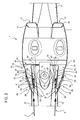
Figure 2 shows a top plan view of an air intake of theFigure 1 helicopter; -
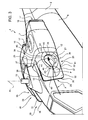
Figure 3 shows a larger-scale side view in perspective of theFigure 2 air intake; -
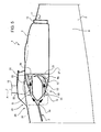
Figure 4 shows a side view of theFigure 2 and3 air intake; -
Figure 5 shows a side view of theFigure 2 and3 air intake with parts removed for clarity; -
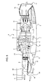
Figure 6 shows an operating diagram, with parts removed for clarity, of an engine of theFigure 1 helicopter and of a section of theFigure 2-5 air intake. - Number 1 in
Figure 1 indicates a helicopter substantially comprising afuselage 2 with anose 5; a main rotor 3 fitted to the top offuselage 2 and rotating about an axis A; and a tail rotor 4 fitted to a tail fin projecting fromfuselage 2 at the opposite end tonose 5, and rotating about a second axis crosswise to axis A. - Helicopter 1 comprises two engines 6 (only one shown in
Figure 6 ) housed in respective housings defined by a supportingbody 7 and located alongsiderespective sides 8 offuselage 2. - Helicopter 1 comprises two transmissions 9 (only one shown in
Figure 6 ) connecting the output shafts of respective engines 6 to a shaft 10 (only shown partly inFigures 3 ,4 ,5 ) for rotating main rotor 3 about axis A. More specifically, the output shafts of engines 6 extend along respective axes B (only one shown inFigure 6 ). - Each engine 6 performs in the same way as an open-thermodynamic-cycle gas turbine, and substantially comprises (
Figure 6 ) : - a
compressor 11 having a fresh-air intake conduit 12 and for compressing the fresh-air intake; - a
combustion chamber 13 in which the air compressed bycompressor 11 reacts with a fuel to produce high-temperature burnt gas; and - a
turbine 14 in which the high-temperature burnt gas fromcombustion chamber 13 expands to rotate the output shaft of engine 6. - Each engine 6 also comprises :
- a
convergent nozzle 15 downstream fromturbine 14 to accelerate the burnt gas; and - an
exhaust conduit 16 for discharging the burnt gas and terminating in a respective opening 17 in supportingbody 7. - For each engine 6, helicopter 1 advantageously comprises an
air intake 20, in turn comprising : - a
first inlet 21 connected fluidically to conduit 12; - two
inlets 22 connected fluidically to a housing 23 (Figure 6 )housing transmission 9; - deflecting means interacting, in use, with an airflow F outside helicopter 1 (
Figures 2 to 5 ) to divide the airflow into a first and second airflow; and - guide means for guiding the first airflow along a first path P (
Figures 2 to 5 ) extending from the deflecting means to inlet 21, and for guiding the second airflow along two second paths Q (Figures 2 and5 ) separate from path P and extending from the deflecting means toinlets 22. - It should be pointed out that "separate" is intended here to mean that paths P and Q of the first and second airflow at no point intersect downstream from the deflecting means.
- More specifically,
air intakes 20 are located alongsiderespective sides 8, and project towardsnose 5 from afront end 25 of supportingbody 7 facingnose 5. - More specifically,
end 25 of supportingbody 7 has twoedges 26 alongsidefuselage 2; and twoedges 27 extending crosswise tofuselage 2 and between respective facing ends ofedges 26. -
Air intakes 20 are preferably integral with each other. -
Air intakes 20 obviously being identical, only one is described below for the sake of simplicity. - In the example shown in the drawings,
air intake 20 comprises (Figures 2 to 5 ) : - a
flat wall 29 which has afree end edge 30 at the opposite end toend 25, and defines asurface 31 facingfuselage 2, and asurface 32 on the opposite side tosurface 31; - a
wall 35 comprising anend portion 36 cooperating withend 25; and amain portion 37 cooperating withsurface 32 and defininginlet 21; and - a wall 50 (
Figure 2 ) comprising anend portion 51 cooperating withend 25; and amain portion 52 interposed betweensurface 32 andrelative side 8, and defininginlets 22. - More specifically, the deflecting means are defined by
edge 30 which performs substantially in the same way as the leading edge of a wing to divert the first and second airflow ontosurfaces wall 29. - In addition to
edge 30, the contour ofwall 29 is also defined by twoedges 33 converging inedge 30 in the direction fromend 25 toedge 30. -
Main portion 37 ofwall 35 extends fromend portion 36 towardsnose 5 offuselage 2. -
End portion 36 is larger thanmain portion 37 in a direction parallel toedge 27, and is smaller thanmain portion 37 lengthwise offuselage 2. -
End portion 36 of eachwall 35 is integral withend portion 36 of the other wall 35 (Figure 2 ). -
Main portion 37 has a curvedfirst end edge 38 cooperating withsurface 32; and a curvedsecond edge 39opposite edge 38 and at a distance fromsurface 32. - More specifically (
Figures 3 ,4 )edge 38 comprises anend portion 40 parallel toedge 30 and interposed betweenedge 30 andend portion 36; and twoportions 41 converging towardsedge 30 in the direction fromend portion 36 toedge 30. -
Portions 41 are located on opposite sides ofportion 40. - Edge 39 is curved and substantially comprises an arc-
shaped portion 42 on theside facing end 25; and aportion 43 elongated towardsedge 30, connected toportion 42, and located on theside facing portion 40. - More specifically (
Figures 3 ,4 ),portion 42 extends along an arc of roughly 180°, andportion 43 is located outside the sector subtended byportion 42. - As shown in
Figure 2 ,edge 39 extends obliquely with respect to axis A. - The contour of
inlet 21 comprises an arc-shapedfirst portion 45; and asecond portion 46 defining a tip located outside the circumference defined byportion 45. -
Portion 45 is located on theside facing end 25, andportion 46 on theside facing portion 40. - More specifically,
portion 46 comprises two segments converging in the direction fromportion 45 toportion 40, and having first ends connected to respective ends ofportion 45, and second ends opposite the first ends and connected to each other. -
Portion 46 is located outside the sector defined byportion 45. -
Inlet 21 is closer thanedge 39 tosurface 32. - More specifically,
main portion 37 ofedge 35 extends at increasing distances fromsurface 32 in the direction fromedge 38 toedge 39, and at decreasing distances fromsurface 32 in the direction fromedge 39 to inlet 21 (Figure 3 ). - In other words, the thickness of
main portion 37 increases in the direction fromedge 38 toedge 39, and decreases in the direction fromedge 39 toinlet 21. - The projection of the contour of
inlet 21 ontosurface 32 lies within the projection of the contour ofedge 39 ontosurface 32. - The projection of the contour of
edge 39 ontosurface 32 lies withinedge 38. - The projections of
portions inlet 21 ontosurface 32 are surrounded by the projections ofportions surface 32. - The
main portion 52 ofwall 50 comprises twosurfaces 53 definingrespective inlets 22 and converging in arounded edge 54 in the direction fromend portion 51 toedge 30 ofwall 29. -
Inlets 22 in the example shown are rectangular and open into respective conduits 55 (Figure 5 ) terminating insidehousing 23 of transmission 9 (Figure 6 ). - More specifically,
edge 54 is interposed betweenend 25 andedge 30. - The guide means of each
air intake 20 comprise : -
surface 32, and the portion ofwall 35 interposed betweenedge 30 andinlet 21 and for guiding the first airflow along path P fromedge 30 toinlet 21; and -
surface 31, and the portions ofsurfaces 53 interposed betweenedge 30 andinlets 22 and for guiding the second airflow along paths Q fromedge 30 toinlets 22. - More specifically, each path Q is bounded laterally by a
relative side 8 and by arelative surface 31, and each path P extends on the opposite side ofrelative wall 29 to relative path Q. - Engine 6 also comprises a
tapping device 18 surroundingcompressor 11 and for drawing off a quota (indicated I inFigure 6 ) of the first airflow upstream fromcompressor 11, and feeding quota I tonozzle 15. - Fresh-air quota I thus mixes with the hot burnt gas flowing through
nozzle 15 to cool the exhaust gas from opening 17 and so reduce the overall radiation emitted by helicopter 1 in the infrared frequency. - In other words,
conduit 16 also functions as an ejector by activating, by means of the gas accelerated innozzle 15, an airflow which originates inhousing 23, coolstransmission 9 to a certain extent, and eventually mixes with the burnt gas insideconduit 16. - In actual use, as helicopter 1 moves forward, airflow F strikes edges 30 of
walls 29, and is diverted byedges 30 to form first and second airflows along respective paths P, Q. - More specifically, the first airflows flow along
surfaces 32 ofrelative walls 29 and along the portions ofwalls 35 interposed betweensurfaces 32 andrespective inlets 21, and finally throughinlets 21 and alongintake conduits 12 of engines 6. - Inside
conduits 12,devices 18 draw off respective quotas I of the first airflows upstream fromrespective compressors 11, and feed them directly tonozzles 15. More specifically, the drawn-off quotas I are less than the respective remaining portions (indicated L inFigure 6 ) of the respective first airflows. - The remaining portions L of the first airflows are compressed by
respective compressors 11, and react with the fuel insiderespective combustion chambers 13 to produce hot pressurized burnt gas, which expands insiderespective turbines 14 and flows alongnozzles 15 to rotate the output shafts of engines 6 about respectiveaxes A. Transmissions 9 transmit motion from the output shafts of engines 6 to thedrive shaft 10 of rotor 3. - Inside
nozzles 15, the hot burnt gas mixes with the fresh-air quotas I tapped bydevices 18, thus cooling the exhaust gas discharged byconduit 16 and indicated M inFigure 6 . - The second airflows flow along
surfaces 31 ofrelative walls 29, along the portions ofsurfaces 53 interposed betweeninlets 22 andrelative edges 54, and finally throughinlets 22 and alongconduits 55 tohousings 23 oftransmissions 9, where they cooltransmissions 9 either directly or by means of a radiator. - The advantages of helicopter 1 according to the present invention will be clear from the above description.
- In particular, edge 30 of each
air intake 20 divides the airflow F on it into a first and second airflow, which reachrespective inlets - As a result, air intake by
conduits 12 throughinlets 21 is unaffected by the airflow throughinlets 22, and by which to coolhousing 23 oftransmission 9, over a wide range of yaw angles of helicopter 1, i.e. a wide range of angular positions offuselage 2 with respect to axis A. - Consequently, an increase in the second airflows through
inlets 22 does not reduce the corresponding first airflows, and so does not impair the efficiency ofcompressor 11 and therefore of engine 6. - Moreover, because
inlets 22 are located on thefuselage 2 side, andinlets 21 on the opposite side tofuselage 2, the turbulence generated by aerodynamic interaction between helicopter 1 and airflow F is more predominant in the second airflows than in the first. - Paths P and Q being separate prevents this turbulence from being transmitted to the first airflows.
- The first airflow along
conduit 12 and predominantly drawn bycompressor 11 is therefore substantially laminar, and so improves the efficiency of engines 6 over a wide range of yaw angles of helicopter 1. - In addition, since air intake by engines 6 is constant, in quantity and flow conditions, over a wide range of yaw angles of helicopter 1, engines 6 have similar operating temperatures, and can therefore be coupled in temperature to improve the overall performance of helicopter 1.
- Another advantage of separating paths P and Q lies in the second airflows being undisturbed by the first, and so being substantially constant over a wide range of yaw angles of helicopter 1, thus greatly reducing the risk of in-mission overheating of
transmission 9. -
Walls respective inlets - Finally,
air intake 20 provides, with a single device, for drawing in both first and second airflows for supplyingcompressors 11 of engines 6 andcooling transmissions 9 and the exhaust gas respectively. - Clearly, changes may be made to helicopter 1 as described herein without, however, departing from the scope of the present invention.
- In particular, helicopter 1 may have one engine 6 and one
air intake 20. -
Walls 53 may have oneinlet 22. - And the shape of
inlets conduits
Claims (12)
- A helicopter (1) comprising:- an engine (6) comprising a combustion air intake conduit (12);- a main rotor (3) connected functionally to said engine (6); and- a transmission (9) interposed functionally between said main rotor (3) and said engine (6) and housed in a housing (23);
and being characterized by comprising at least one air intake (20) in turn comprising :a first inlet (21) connected fluidically to said intake conduit (12);- at least one second inlet (22) connected fluidically to said housing (23);- deflecting means (30) interacting, in use, with an airflow (F) to divide the airflow (F) into a first and a second airflow; and- guide means (31, 32, 37, 53) for guiding said first airflow along a first path (P) extending from said deflecting means (30) to said first inlet (21), and for guiding said second airflow along a second path (Q) separate from said first path (P) and extending from said deflecting means (30) to said second inlet (22). - A helicopter as claimed in Claim 1, characterized in that said air intake (20) comprises a first wall (29) defining said deflecting means (30).
- A helicopter as claimed in Claim 2, characterized in that said deflecting means (30) are defined by a free first end edge (30) of said first wall (29).
- A helicopter as claimed in Claim 2 or 3, of the type comprising a fuselage (2), and characterized in that said second path (Q) extends between said first wall (29) and said fuselage (2), and said first path (P) extends on the opposite side of said first wall (29) to said fuselage (2).
- A helicopter as claimed in Claim 4, characterized in that said air intake (20) comprises a second wall (35) and a third wall (50) defining said first and said second inlet (21, 22) respectively; said third wall (50) extending between a first surface (31) of said first wall (29) and said fuselage (2), and said second wall (35) projecting from a second surface (32), opposite said first surface (31), of said first wall (29); said guide means (31, 32, 37, 53) being defined by said first and second surface (31, 32) of said first wall (29), by the portion of said second wall (35) extending between said second surface (32) and said first inlet (21), and by the portion of said third wall (50) extending between said first surface (31) and said second inlet (22).
- A helicopter as claimed in Claim 5, characterized in that said second wall (35) comprises a second end edge (38) cooperating at least partly with said second surface (32) of said first wall (29); and a free third end edge (39) opposite said second end edge (38); said first inlet (21) extending at a distance from said second surface (32) smaller than the distance between said third end edge (39) and said second surface (32).
- A helicopter as claimed in Claim 6, characterized in that the thickness of said second wall (35), measured perpendicularly to said second surface (32), increases in the direction from said second end edge (38) to said third end edge (39), and decreases in the direction from said third end edge (39) to said first inlet (21).
- A helicopter as claimed in any one of Claims 3 to 7, characterized in that the contour of said first inlet (21) comprises a first tip portion (46), and a second arc-shaped portion (45) located on the opposite side of said first tip portion (46) to the free said first end edge (30) of said first wall (29); said first tip portion (46) diverging in the direction from the free said first end edge (30) of said first wall (29) to said second arc-shaped portion (45).
- A helicopter as claimed in any one of Claims 5 to 8, characterized in that said third wall (50) comprises a free fourth end edge (54), and a third and fourth surface (53) converging in said fourth end edge (54); said third and fourth surface (53) each defining a respective said second inlet (22).
- A helicopter as claimed in Claim 9, characterized in that said fourth end edge (54) of said third wall (50) is interposed between the free said first end edge (30) of said first wall (29) and said second inlets (22).
- A helicopter as claimed in any one of Claims 5 to 10, characterized in that said first, second, and third wall (29, 35, 50) are integral with one another.
- A helicopter as claimed in any one of the foregoing Claims, characterized in that said engine (6) comprises:- a compressor (11) which in use draws a portion (L) of the air flowing through said first inlet (21) and said intake conduit (12);- a combustion chamber (13) which in use is supplied with air compressed by said compressor (11), and causes said compressed air to react with a fuel to produce high-temperature burnt gas;- a turbine (14) which in use expands said burnt gas;- a nozzle (15) for varying the speed of the burnt gas expanded in said turbine (14); and- an exhaust conduit (16) located downstream from said nozzle (15) to expel said burnt gas from said helicopter (1);
said helicopter (1) being characterized by also comprising a tap line for drawing off a quota (I) of said first airflow upstream from said compressor (11), and feeding said quota (I) downstream from said turbine (14) to mix said quota (I) with said burnt gas from said turbine (14).
Priority Applications (10)
| Application Number | Priority Date | Filing Date | Title |
|---|---|---|---|
| AT08425408T ATE477177T1 (en) | 2008-06-10 | 2008-06-10 | HELICOPTER |
| EP08425408A EP2133265B1 (en) | 2008-06-10 | 2008-06-10 | Helicopter |
| PL08425408T PL2133265T3 (en) | 2008-06-10 | 2008-06-10 | Helicopter |
| PT08425408T PT2133265E (en) | 2008-06-10 | 2008-06-10 | Helicopter |
| DE602008002151T DE602008002151D1 (en) | 2008-06-10 | 2008-06-10 | helicopter |
| RU2009121507/11A RU2499736C2 (en) | 2008-06-10 | 2009-06-08 | Helicopter |
| US12/481,215 US8113461B2 (en) | 2008-06-10 | 2009-06-09 | Helicopter |
| JP2009139226A JP5524513B2 (en) | 2008-06-10 | 2009-06-10 | Helicopter |
| CN2009101639079A CN101612991B (en) | 2008-06-10 | 2009-06-10 | Helicopter |
| KR1020090051478A KR101586008B1 (en) | 2008-06-10 | 2009-06-10 | Helicopter |
Applications Claiming Priority (1)
| Application Number | Priority Date | Filing Date | Title |
|---|---|---|---|
| EP08425408A EP2133265B1 (en) | 2008-06-10 | 2008-06-10 | Helicopter |
Publications (2)
| Publication Number | Publication Date |
|---|---|
| EP2133265A1 EP2133265A1 (en) | 2009-12-16 |
| EP2133265B1 true EP2133265B1 (en) | 2010-08-11 |
Family
ID=39761026
Family Applications (1)
| Application Number | Title | Priority Date | Filing Date |
|---|---|---|---|
| EP08425408A Active EP2133265B1 (en) | 2008-06-10 | 2008-06-10 | Helicopter |
Country Status (10)
| Country | Link |
|---|---|
| US (1) | US8113461B2 (en) |
| EP (1) | EP2133265B1 (en) |
| JP (1) | JP5524513B2 (en) |
| KR (1) | KR101586008B1 (en) |
| CN (1) | CN101612991B (en) |
| AT (1) | ATE477177T1 (en) |
| DE (1) | DE602008002151D1 (en) |
| PL (1) | PL2133265T3 (en) |
| PT (1) | PT2133265E (en) |
| RU (1) | RU2499736C2 (en) |
Cited By (1)
| Publication number | Priority date | Publication date | Assignee | Title |
|---|---|---|---|---|
| EP2995556A1 (en) | 2014-09-12 | 2016-03-16 | AIRBUS HELICOPTERS DEUTSCHLAND GmbH | An aircraft with an air intake for an air breathing propulsion engine |
Families Citing this family (18)
| Publication number | Priority date | Publication date | Assignee | Title |
|---|---|---|---|---|
| EP2040818A2 (en) * | 2006-07-14 | 2009-04-01 | Aerospace Filtration Systems, Inc. | Aircraft engine inlet pivotable barrier filter |
| EP2678226B1 (en) * | 2011-04-28 | 2015-01-21 | Bell Helicopter Textron Inc. | Self-aligning inlet plenum system for rotorcraft |
| US9051057B2 (en) * | 2011-12-28 | 2015-06-09 | Embraer S.A. | Aircraft air inlet diverter assemblies with improved aerodynamic characteristics |
| FR2986275B1 (en) * | 2012-02-01 | 2016-07-01 | Turbomeca | GAS TURBINE EXHAUST GAS EJECTION METHOD AND OPTIMIZED CONFIGURATION EXHAUST ASSEMBLY |
| US9234460B2 (en) * | 2012-05-22 | 2016-01-12 | Sikorsky Aircraft Corporation | Engine inlet |
| JP5707367B2 (en) | 2012-07-20 | 2015-04-30 | ヤマハ発動機株式会社 | Unmanned helicopter |
| EP2853493B1 (en) * | 2013-09-30 | 2016-08-10 | AIRBUS HELICOPTERS DEUTSCHLAND GmbH | Helicopter with engine air intakes |
| US9574497B2 (en) * | 2013-10-08 | 2017-02-21 | Bell Helicopter Textron Inc. | Engine mounted inlet plenum for a rotorcraft |
| US9656760B2 (en) * | 2013-11-07 | 2017-05-23 | Sikorsky Aircraft Corporation | Variable geometry helicopter engine inlet |
| US9586692B2 (en) * | 2014-04-14 | 2017-03-07 | Sikorsky Aircraft Corporation | Engine inlet configuration |
| PL3056423T3 (en) * | 2015-02-16 | 2018-04-30 | Airbus Helicopters Deutschland GmbH | An aircraft with a fuselage that defines at least an interior region and a drive system accommodating region |
| US10662859B1 (en) * | 2016-05-02 | 2020-05-26 | Northwest Uld, Inc. | Dual flap active inlet cooling shroud |
| KR102174214B1 (en) * | 2019-01-02 | 2020-11-04 | 한국항공우주산업 주식회사 | Anti-icing apparatus for air suction hole of engine |
| JP7235582B2 (en) * | 2019-05-07 | 2023-03-08 | 株式会社Subaru | cooling duct |
| US12208909B2 (en) * | 2019-09-08 | 2025-01-28 | Textron Innovations Inc. | Aircraft with bifurcated air inlet |
| JP7333267B2 (en) * | 2019-12-26 | 2023-08-24 | 川崎重工業株式会社 | helicopter |
| RU2737979C1 (en) * | 2020-03-23 | 2020-12-07 | Константин Борисович Махнюк | Helicopter |
| EP3904217B1 (en) * | 2020-04-27 | 2022-09-28 | LEONARDO S.p.A. | Aircraft capable of hovering |
Family Cites Families (16)
| Publication number | Priority date | Publication date | Assignee | Title |
|---|---|---|---|---|
| US2699906A (en) * | 1949-10-25 | 1955-01-18 | Northrop Aircraft Inc | Air inlet for airplane gaseous combustion turbine engines |
| GB1201096A (en) * | 1966-11-15 | 1970-08-05 | United Aircraft Corp | Air particle separator |
| FR1512579A (en) * | 1966-12-30 | 1968-02-09 | Sud Aviation | Lift and thruster device for a combined helicopter-autogyro jet aircraft |
| IT1183880B (en) * | 1985-06-07 | 1987-10-22 | Agusta Aeronaut Costr | HELICOPTER WITH TURBINE POWER SUPPLY UNIT PROVIDED WITH EXHAUST MASK DEVICE |
| DE3709924A1 (en) * | 1987-03-26 | 1988-10-13 | Porsche Ag | AIRPLANE, PREFERABLY HELICOPTER |
| DE3942022A1 (en) * | 1989-12-20 | 1991-06-27 | Mtu Muenchen Gmbh | METHOD AND DEVICE FOR COOLING AN AIRCRAFT ENGINE |
| JPH04159198A (en) * | 1990-10-22 | 1992-06-02 | Mitsubishi Heavy Ind Ltd | Helicopter |
| US5102067A (en) * | 1991-04-11 | 1992-04-07 | United Technologies Corporation | Integrated helicopter empennage structure |
| JPH05193579A (en) * | 1992-01-20 | 1993-08-03 | Mitsubishi Heavy Ind Ltd | Turboshaft engine |
| JPH05332122A (en) * | 1992-06-01 | 1993-12-14 | Ishikawajima Harima Heavy Ind Co Ltd | Helicopter engine |
| US5697394A (en) * | 1993-03-02 | 1997-12-16 | United Technologies Corporation | Low observable engine air inlet system |
| US5649678A (en) * | 1994-04-20 | 1997-07-22 | Denel (Proprietary) Limited | Operation of a helicopter |
| DE19524731A1 (en) * | 1995-07-07 | 1997-01-09 | Bmw Rolls Royce Gmbh | Turboprop engine with an air-oil cooler |
| DE10200459A1 (en) * | 2002-01-09 | 2003-07-24 | Airbus Gmbh | Air intake for an auxiliary engine in an aircraft |
| US20050056724A1 (en) * | 2003-09-11 | 2005-03-17 | Safe Flight Instrument Corporation | Helicopter turbine engine protection system |
| RU2299157C1 (en) * | 2005-12-06 | 2007-05-20 | Открытое акционерное общество "Камов" | Helicopter engine oil cooling system |
-
2008
- 2008-06-10 PT PT08425408T patent/PT2133265E/en unknown
- 2008-06-10 DE DE602008002151T patent/DE602008002151D1/en active Active
- 2008-06-10 AT AT08425408T patent/ATE477177T1/en not_active IP Right Cessation
- 2008-06-10 PL PL08425408T patent/PL2133265T3/en unknown
- 2008-06-10 EP EP08425408A patent/EP2133265B1/en active Active
-
2009
- 2009-06-08 RU RU2009121507/11A patent/RU2499736C2/en active
- 2009-06-09 US US12/481,215 patent/US8113461B2/en active Active
- 2009-06-10 CN CN2009101639079A patent/CN101612991B/en active Active
- 2009-06-10 KR KR1020090051478A patent/KR101586008B1/en active Active
- 2009-06-10 JP JP2009139226A patent/JP5524513B2/en active Active
Cited By (1)
| Publication number | Priority date | Publication date | Assignee | Title |
|---|---|---|---|---|
| EP2995556A1 (en) | 2014-09-12 | 2016-03-16 | AIRBUS HELICOPTERS DEUTSCHLAND GmbH | An aircraft with an air intake for an air breathing propulsion engine |
Also Published As
| Publication number | Publication date |
|---|---|
| US20100230530A1 (en) | 2010-09-16 |
| JP2009298399A (en) | 2009-12-24 |
| PT2133265E (en) | 2010-10-18 |
| KR20090128345A (en) | 2009-12-15 |
| RU2499736C2 (en) | 2013-11-27 |
| KR101586008B1 (en) | 2016-01-15 |
| CN101612991A (en) | 2009-12-30 |
| PL2133265T3 (en) | 2011-01-31 |
| ATE477177T1 (en) | 2010-08-15 |
| CN101612991B (en) | 2013-05-22 |
| DE602008002151D1 (en) | 2010-09-23 |
| RU2009121507A (en) | 2010-12-20 |
| JP5524513B2 (en) | 2014-06-18 |
| EP2133265A1 (en) | 2009-12-16 |
| US8113461B2 (en) | 2012-02-14 |
Similar Documents
| Publication | Publication Date | Title |
|---|---|---|
| EP2133265B1 (en) | Helicopter | |
| US4892269A (en) | Spinner ducted exhaust for pusher turboprop engines | |
| US4930725A (en) | Pusher propeller installation for turboprop engines | |
| EP2098714B1 (en) | High bypass-ratio turbofan jet engine | |
| US10507930B2 (en) | Airplane with angled-mounted turboprop engine | |
| US20180328284A1 (en) | Low noise aeroengine inlet system | |
| CN113417891B (en) | Centrifugal compressor anti-icing air entraining structure and engine | |
| JP2011256859A (en) | Flow mixing vent system | |
| US10794280B2 (en) | Air intake for gas turbine engine | |
| CN107013268A (en) | Compression radome fairing for jet engine exhaust | |
| EP2932068A1 (en) | Gas turbine engine with cooling scheme for drive gear system and pitch control | |
| US10875654B2 (en) | Drive device for an aircraft | |
| US20160090174A1 (en) | Reaction drive blade tip with turning vanes | |
| EP3388648B1 (en) | Inlet duct | |
| US10377475B2 (en) | Nozzles for a reaction drive blade tip with turning vanes | |
| US20140260183A1 (en) | Variable cycle intake for reverse core engine | |
| WO1989010300A1 (en) | Spinner ducted exhaust for pusher turboprop engines | |
| CN119982208B (en) | Engine systems and aircraft | |
| US20230159181A1 (en) | Aircraft capable of hovering | |
| US10655630B2 (en) | Bypass duct fairing for low bypass ratio turbofan engine and turbofan engine therewith |
Legal Events
| Date | Code | Title | Description |
|---|---|---|---|
| PUAI | Public reference made under article 153(3) epc to a published international application that has entered the european phase |
Free format text: ORIGINAL CODE: 0009012 |
|
| 17P | Request for examination filed |
Effective date: 20090525 |
|
| AK | Designated contracting states |
Kind code of ref document: A1 Designated state(s): AT BE BG CH CY CZ DE DK EE ES FI FR GB GR HR HU IE IS IT LI LT LU LV MC MT NL NO PL PT RO SE SI SK TR |
|
| AX | Request for extension of the european patent |
Extension state: AL BA MK RS |
|
| GRAP | Despatch of communication of intention to grant a patent |
Free format text: ORIGINAL CODE: EPIDOSNIGR1 |
|
| GRAS | Grant fee paid |
Free format text: ORIGINAL CODE: EPIDOSNIGR3 |
|
| RIN1 | Information on inventor provided before grant (corrected) |
Inventor name: BALLERIO, DANTE Inventor name: NANNONI, FABIO Inventor name: SCANDROGLIO, ALESSANDRO |
|
| GRAA | (expected) grant |
Free format text: ORIGINAL CODE: 0009210 |
|
| AK | Designated contracting states |
Kind code of ref document: B1 Designated state(s): AT BE BG CH CY CZ DE DK EE ES FI FR GB GR HR HU IE IS IT LI LT LU LV MC MT NL NO PL PT RO SE SI SK TR |
|
| REG | Reference to a national code |
Ref country code: GB Ref legal event code: FG4D |
|
| REG | Reference to a national code |
Ref country code: CH Ref legal event code: EP |
|
| AKX | Designation fees paid |
Designated state(s): AT BE BG CH CY CZ DE DK EE ES FI FR GB GR HR HU IE IS IT LI LT LU LV MC MT NL NO PL PT RO SE SI SK TR |
|
| REG | Reference to a national code |
Ref country code: IE Ref legal event code: FG4D |
|
| REF | Corresponds to: |
Ref document number: 602008002151 Country of ref document: DE Date of ref document: 20100923 Kind code of ref document: P |
|
| REG | Reference to a national code |
Ref country code: NL Ref legal event code: VDEP Effective date: 20100811 |
|
| LTIE | Lt: invalidation of european patent or patent extension |
Effective date: 20100811 |
|
| PG25 | Lapsed in a contracting state [announced via postgrant information from national office to epo] |
Ref country code: AT Free format text: LAPSE BECAUSE OF FAILURE TO SUBMIT A TRANSLATION OF THE DESCRIPTION OR TO PAY THE FEE WITHIN THE PRESCRIBED TIME-LIMIT Effective date: 20100811 Ref country code: NL Free format text: LAPSE BECAUSE OF FAILURE TO SUBMIT A TRANSLATION OF THE DESCRIPTION OR TO PAY THE FEE WITHIN THE PRESCRIBED TIME-LIMIT Effective date: 20100811 Ref country code: NO Free format text: LAPSE BECAUSE OF FAILURE TO SUBMIT A TRANSLATION OF THE DESCRIPTION OR TO PAY THE FEE WITHIN THE PRESCRIBED TIME-LIMIT Effective date: 20101111 Ref country code: LT Free format text: LAPSE BECAUSE OF FAILURE TO SUBMIT A TRANSLATION OF THE DESCRIPTION OR TO PAY THE FEE WITHIN THE PRESCRIBED TIME-LIMIT Effective date: 20100811 Ref country code: FI Free format text: LAPSE BECAUSE OF FAILURE TO SUBMIT A TRANSLATION OF THE DESCRIPTION OR TO PAY THE FEE WITHIN THE PRESCRIBED TIME-LIMIT Effective date: 20100811 |
|
| REG | Reference to a national code |
Ref country code: PL Ref legal event code: T3 |
|
| PG25 | Lapsed in a contracting state [announced via postgrant information from national office to epo] |
Ref country code: IS Free format text: LAPSE BECAUSE OF FAILURE TO SUBMIT A TRANSLATION OF THE DESCRIPTION OR TO PAY THE FEE WITHIN THE PRESCRIBED TIME-LIMIT Effective date: 20101211 Ref country code: HR Free format text: LAPSE BECAUSE OF FAILURE TO SUBMIT A TRANSLATION OF THE DESCRIPTION OR TO PAY THE FEE WITHIN THE PRESCRIBED TIME-LIMIT Effective date: 20100811 Ref country code: CY Free format text: LAPSE BECAUSE OF FAILURE TO SUBMIT A TRANSLATION OF THE DESCRIPTION OR TO PAY THE FEE WITHIN THE PRESCRIBED TIME-LIMIT Effective date: 20100811 Ref country code: BG Free format text: LAPSE BECAUSE OF FAILURE TO SUBMIT A TRANSLATION OF THE DESCRIPTION OR TO PAY THE FEE WITHIN THE PRESCRIBED TIME-LIMIT Effective date: 20101111 Ref country code: SI Free format text: LAPSE BECAUSE OF FAILURE TO SUBMIT A TRANSLATION OF THE DESCRIPTION OR TO PAY THE FEE WITHIN THE PRESCRIBED TIME-LIMIT Effective date: 20100811 |
|
| PG25 | Lapsed in a contracting state [announced via postgrant information from national office to epo] |
Ref country code: SE Free format text: LAPSE BECAUSE OF FAILURE TO SUBMIT A TRANSLATION OF THE DESCRIPTION OR TO PAY THE FEE WITHIN THE PRESCRIBED TIME-LIMIT Effective date: 20100811 Ref country code: BE Free format text: LAPSE BECAUSE OF FAILURE TO SUBMIT A TRANSLATION OF THE DESCRIPTION OR TO PAY THE FEE WITHIN THE PRESCRIBED TIME-LIMIT Effective date: 20100811 Ref country code: GR Free format text: LAPSE BECAUSE OF FAILURE TO SUBMIT A TRANSLATION OF THE DESCRIPTION OR TO PAY THE FEE WITHIN THE PRESCRIBED TIME-LIMIT Effective date: 20101112 Ref country code: LV Free format text: LAPSE BECAUSE OF FAILURE TO SUBMIT A TRANSLATION OF THE DESCRIPTION OR TO PAY THE FEE WITHIN THE PRESCRIBED TIME-LIMIT Effective date: 20100811 |
|
| PG25 | Lapsed in a contracting state [announced via postgrant information from national office to epo] |
Ref country code: DK Free format text: LAPSE BECAUSE OF FAILURE TO SUBMIT A TRANSLATION OF THE DESCRIPTION OR TO PAY THE FEE WITHIN THE PRESCRIBED TIME-LIMIT Effective date: 20100811 |
|
| PG25 | Lapsed in a contracting state [announced via postgrant information from national office to epo] |
Ref country code: SK Free format text: LAPSE BECAUSE OF FAILURE TO SUBMIT A TRANSLATION OF THE DESCRIPTION OR TO PAY THE FEE WITHIN THE PRESCRIBED TIME-LIMIT Effective date: 20100811 Ref country code: EE Free format text: LAPSE BECAUSE OF FAILURE TO SUBMIT A TRANSLATION OF THE DESCRIPTION OR TO PAY THE FEE WITHIN THE PRESCRIBED TIME-LIMIT Effective date: 20100811 Ref country code: RO Free format text: LAPSE BECAUSE OF FAILURE TO SUBMIT A TRANSLATION OF THE DESCRIPTION OR TO PAY THE FEE WITHIN THE PRESCRIBED TIME-LIMIT Effective date: 20100811 Ref country code: CZ Free format text: LAPSE BECAUSE OF FAILURE TO SUBMIT A TRANSLATION OF THE DESCRIPTION OR TO PAY THE FEE WITHIN THE PRESCRIBED TIME-LIMIT Effective date: 20100811 |
|
| PLBE | No opposition filed within time limit |
Free format text: ORIGINAL CODE: 0009261 |
|
| STAA | Information on the status of an ep patent application or granted ep patent |
Free format text: STATUS: NO OPPOSITION FILED WITHIN TIME LIMIT |
|
| PG25 | Lapsed in a contracting state [announced via postgrant information from national office to epo] |
Ref country code: ES Free format text: LAPSE BECAUSE OF FAILURE TO SUBMIT A TRANSLATION OF THE DESCRIPTION OR TO PAY THE FEE WITHIN THE PRESCRIBED TIME-LIMIT Effective date: 20101122 |
|
| 26N | No opposition filed |
Effective date: 20110512 |
|
| REG | Reference to a national code |
Ref country code: DE Ref legal event code: R097 Ref document number: 602008002151 Country of ref document: DE Effective date: 20110512 |
|
| PG25 | Lapsed in a contracting state [announced via postgrant information from national office to epo] |
Ref country code: MT Free format text: LAPSE BECAUSE OF FAILURE TO SUBMIT A TRANSLATION OF THE DESCRIPTION OR TO PAY THE FEE WITHIN THE PRESCRIBED TIME-LIMIT Effective date: 20100811 |
|
| REG | Reference to a national code |
Ref country code: IE Ref legal event code: MM4A |
|
| PG25 | Lapsed in a contracting state [announced via postgrant information from national office to epo] |
Ref country code: IE Free format text: LAPSE BECAUSE OF NON-PAYMENT OF DUE FEES Effective date: 20110610 |
|
| REG | Reference to a national code |
Ref country code: CH Ref legal event code: PL |
|
| REG | Reference to a national code |
Ref country code: CH Ref legal event code: PL |
|
| PG25 | Lapsed in a contracting state [announced via postgrant information from national office to epo] |
Ref country code: MC Free format text: LAPSE BECAUSE OF NON-PAYMENT OF DUE FEES Effective date: 20110630 Ref country code: CH Free format text: LAPSE BECAUSE OF NON-PAYMENT OF DUE FEES Effective date: 20120630 Ref country code: LI Free format text: LAPSE BECAUSE OF NON-PAYMENT OF DUE FEES Effective date: 20120630 |
|
| PG25 | Lapsed in a contracting state [announced via postgrant information from national office to epo] |
Ref country code: LU Free format text: LAPSE BECAUSE OF NON-PAYMENT OF DUE FEES Effective date: 20110610 |
|
| PG25 | Lapsed in a contracting state [announced via postgrant information from national office to epo] |
Ref country code: HU Free format text: LAPSE BECAUSE OF FAILURE TO SUBMIT A TRANSLATION OF THE DESCRIPTION OR TO PAY THE FEE WITHIN THE PRESCRIBED TIME-LIMIT Effective date: 20100811 |
|
| PGFP | Annual fee paid to national office [announced via postgrant information from national office to epo] |
Ref country code: PT Payment date: 20150609 Year of fee payment: 8 |
|
| REG | Reference to a national code |
Ref country code: DE Ref legal event code: R082 Ref document number: 602008002151 Country of ref document: DE Representative=s name: ZENZ PATENTANWAELTE PARTNERSCHAFT MBB, DE |
|
| REG | Reference to a national code |
Ref country code: FR Ref legal event code: PLFP Year of fee payment: 9 |
|
| PG25 | Lapsed in a contracting state [announced via postgrant information from national office to epo] |
Ref country code: PT Free format text: LAPSE BECAUSE OF NON-PAYMENT OF DUE FEES Effective date: 20161212 |
|
| REG | Reference to a national code |
Ref country code: FR Ref legal event code: PLFP Year of fee payment: 10 |
|
| REG | Reference to a national code |
Ref country code: FR Ref legal event code: PLFP Year of fee payment: 11 |
|
| REG | Reference to a national code |
Ref country code: DE Ref legal event code: R082 Ref document number: 602008002151 Country of ref document: DE Representative=s name: ZENZ PATENTANWAELTE PARTNERSCHAFT MBB, DE Ref country code: DE Ref legal event code: R081 Ref document number: 602008002151 Country of ref document: DE Owner name: LEONARDO S.P.A., IT Free format text: FORMER OWNER: AGUSTA S.P.A., SAMARATE, IT |
|
| P01 | Opt-out of the competence of the unified patent court (upc) registered |
Effective date: 20231005 |
|
| PGFP | Annual fee paid to national office [announced via postgrant information from national office to epo] |
Ref country code: PL Payment date: 20250521 Year of fee payment: 18 Ref country code: DE Payment date: 20250626 Year of fee payment: 18 |
|
| PGFP | Annual fee paid to national office [announced via postgrant information from national office to epo] |
Ref country code: GB Payment date: 20250617 Year of fee payment: 18 |
|
| PGFP | Annual fee paid to national office [announced via postgrant information from national office to epo] |
Ref country code: IT Payment date: 20250605 Year of fee payment: 18 |
|
| PGFP | Annual fee paid to national office [announced via postgrant information from national office to epo] |
Ref country code: FR Payment date: 20250624 Year of fee payment: 18 |
|
| PGFP | Annual fee paid to national office [announced via postgrant information from national office to epo] |
Ref country code: TR Payment date: 20250521 Year of fee payment: 18 |