EP2133225A1 - Device for electrical heating in a heating system of a motor vehicle, frame of an electrical device for heating in a heating system and method for production of same - Google Patents
Device for electrical heating in a heating system of a motor vehicle, frame of an electrical device for heating in a heating system and method for production of same Download PDFInfo
- Publication number
- EP2133225A1 EP2133225A1 EP08290538A EP08290538A EP2133225A1 EP 2133225 A1 EP2133225 A1 EP 2133225A1 EP 08290538 A EP08290538 A EP 08290538A EP 08290538 A EP08290538 A EP 08290538A EP 2133225 A1 EP2133225 A1 EP 2133225A1
- Authority
- EP
- European Patent Office
- Prior art keywords
- frame
- heating element
- heating
- electrical
- piece
- Prior art date
- Legal status (The legal status is an assumption and is not a legal conclusion. Google has not performed a legal analysis and makes no representation as to the accuracy of the status listed.)
- Granted
Links
- 238000010438 heat treatment Methods 0.000 title claims abstract description 135
- 238000004519 manufacturing process Methods 0.000 title claims abstract description 12
- 238000005485 electric heating Methods 0.000 claims description 49
- 238000002347 injection Methods 0.000 claims description 17
- 239000007924 injection Substances 0.000 claims description 17
- 238000000034 method Methods 0.000 abstract description 3
- 238000003780 insertion Methods 0.000 description 13
- 230000037431 insertion Effects 0.000 description 13
- 239000003570 air Substances 0.000 description 5
- 238000002485 combustion reaction Methods 0.000 description 3
- 239000000463 material Substances 0.000 description 3
- 239000002826 coolant Substances 0.000 description 2
- 230000005611 electricity Effects 0.000 description 2
- 238000001746 injection moulding Methods 0.000 description 2
- 238000009434 installation Methods 0.000 description 2
- 238000009423 ventilation Methods 0.000 description 2
- 239000012080 ambient air Substances 0.000 description 1
- 238000010276 construction Methods 0.000 description 1
- 230000006735 deficit Effects 0.000 description 1
- 239000000446 fuel Substances 0.000 description 1
- 239000002918 waste heat Substances 0.000 description 1
Images


Classifications
-
- B—PERFORMING OPERATIONS; TRANSPORTING
- B60—VEHICLES IN GENERAL
- B60H—ARRANGEMENTS OF HEATING, COOLING, VENTILATING OR OTHER AIR-TREATING DEVICES SPECIALLY ADAPTED FOR PASSENGER OR GOODS SPACES OF VEHICLES
- B60H1/00—Heating, cooling or ventilating [HVAC] devices
- B60H1/22—Heating, cooling or ventilating [HVAC] devices the heat being derived otherwise than from the propulsion plant
- B60H1/2215—Heating, cooling or ventilating [HVAC] devices the heat being derived otherwise than from the propulsion plant the heat being derived from electric heaters
- B60H1/2225—Heating, cooling or ventilating [HVAC] devices the heat being derived otherwise than from the propulsion plant the heat being derived from electric heaters arrangements of electric heaters for heating air
-
- F—MECHANICAL ENGINEERING; LIGHTING; HEATING; WEAPONS; BLASTING
- F24—HEATING; RANGES; VENTILATING
- F24H—FLUID HEATERS, e.g. WATER OR AIR HEATERS, HAVING HEAT-GENERATING MEANS, e.g. HEAT PUMPS, IN GENERAL
- F24H3/00—Air heaters
- F24H3/02—Air heaters with forced circulation
- F24H3/04—Air heaters with forced circulation the air being in direct contact with the heating medium, e.g. electric heating element
- F24H3/0405—Air heaters with forced circulation the air being in direct contact with the heating medium, e.g. electric heating element using electric energy supply, e.g. the heating medium being a resistive element; Heating by direct contact, i.e. with resistive elements, electrodes and fins being bonded together without additional element in-between
- F24H3/0429—For vehicles
- F24H3/0452—Frame constructions
- F24H3/0458—One-piece frames
-
- H—ELECTRICITY
- H05—ELECTRIC TECHNIQUES NOT OTHERWISE PROVIDED FOR
- H05B—ELECTRIC HEATING; ELECTRIC LIGHT SOURCES NOT OTHERWISE PROVIDED FOR; CIRCUIT ARRANGEMENTS FOR ELECTRIC LIGHT SOURCES, IN GENERAL
- H05B1/00—Details of electric heating devices
- H05B1/02—Automatic switching arrangements specially adapted to apparatus ; Control of heating devices
- H05B1/0227—Applications
- H05B1/023—Industrial applications
- H05B1/0236—Industrial applications for vehicles
-
- H—ELECTRICITY
- H05—ELECTRIC TECHNIQUES NOT OTHERWISE PROVIDED FOR
- H05B—ELECTRIC HEATING; ELECTRIC LIGHT SOURCES NOT OTHERWISE PROVIDED FOR; CIRCUIT ARRANGEMENTS FOR ELECTRIC LIGHT SOURCES, IN GENERAL
- H05B3/00—Ohmic-resistance heating
- H05B3/40—Heating elements having the shape of rods or tubes
- H05B3/42—Heating elements having the shape of rods or tubes non-flexible
- H05B3/48—Heating elements having the shape of rods or tubes non-flexible heating conductor embedded in insulating material
- H05B3/50—Heating elements having the shape of rods or tubes non-flexible heating conductor embedded in insulating material heating conductor arranged in metal tubes, the radiating surface having heat-conducting fins
-
- H—ELECTRICITY
- H05—ELECTRIC TECHNIQUES NOT OTHERWISE PROVIDED FOR
- H05B—ELECTRIC HEATING; ELECTRIC LIGHT SOURCES NOT OTHERWISE PROVIDED FOR; CIRCUIT ARRANGEMENTS FOR ELECTRIC LIGHT SOURCES, IN GENERAL
- H05B3/00—Ohmic-resistance heating
- H05B3/84—Heating arrangements specially adapted for transparent or reflecting areas, e.g. for demisting or de-icing windows, mirrors or vehicle windshields
-
- B—PERFORMING OPERATIONS; TRANSPORTING
- B60—VEHICLES IN GENERAL
- B60H—ARRANGEMENTS OF HEATING, COOLING, VENTILATING OR OTHER AIR-TREATING DEVICES SPECIALLY ADAPTED FOR PASSENGER OR GOODS SPACES OF VEHICLES
- B60H1/00—Heating, cooling or ventilating [HVAC] devices
- B60H1/22—Heating, cooling or ventilating [HVAC] devices the heat being derived otherwise than from the propulsion plant
- B60H2001/2268—Constructional features
- B60H2001/2278—Connectors, water supply, housing, mounting brackets
-
- H—ELECTRICITY
- H05—ELECTRIC TECHNIQUES NOT OTHERWISE PROVIDED FOR
- H05B—ELECTRIC HEATING; ELECTRIC LIGHT SOURCES NOT OTHERWISE PROVIDED FOR; CIRCUIT ARRANGEMENTS FOR ELECTRIC LIGHT SOURCES, IN GENERAL
- H05B2203/00—Aspects relating to Ohmic resistive heating covered by group H05B3/00
- H05B2203/022—Heaters specially adapted for heating gaseous material
- H05B2203/023—Heaters of the type used for electrically heating the air blown in a vehicle compartment by the vehicle heating system
-
- H—ELECTRICITY
- H05—ELECTRIC TECHNIQUES NOT OTHERWISE PROVIDED FOR
- H05B—ELECTRIC HEATING; ELECTRIC LIGHT SOURCES NOT OTHERWISE PROVIDED FOR; CIRCUIT ARRANGEMENTS FOR ELECTRIC LIGHT SOURCES, IN GENERAL
- H05B2203/00—Aspects relating to Ohmic resistive heating covered by group H05B3/00
- H05B2203/035—Electrical circuits used in resistive heating apparatus
Definitions
- the injection mold 50 has a base tool part 51, in which, according to first insertion directions 52, a mold core 53 can be inserted into a tool pocket 54. Accordingly, the injection mold 50 is multi-part, at least formed in two parts. According to the further insertion direction 55, further insert parts (not shown here), such as slides or the like, can be inserted into the basic tool part 51. In this respect, one-piece frames 2 of different shapes can be sprayed with the present injection mold 50.
Landscapes
- Engineering & Computer Science (AREA)
- Physics & Mathematics (AREA)
- Thermal Sciences (AREA)
- Mechanical Engineering (AREA)
- Chemical & Material Sciences (AREA)
- Combustion & Propulsion (AREA)
- General Engineering & Computer Science (AREA)
- Air-Conditioning For Vehicles (AREA)
Abstract
Description
Die Erfindung betrifft einerseits eine Vorrichtung zum elektrischen Zuheizen an einem Heizsystem eines Kraftfahrzeuges, insbesondere einer Fahrgastzelle eines Kraftfahrzeuges, mit einem elektrischen Heizelement und mit einem Rahmen, in welchem das elektrische Heizelement anordenbar ist. Andererseits betrifft die Erfindung einen Rahmen einer elektrischen Vorrichtung zum Zuheizen an einem Heizsystem, insbesondere eines Kraftfahrzeuges, wobei in dem Rahmen ein elektrisches Heizelement gehalten und wobei der Rahmen in einer Aufnahme des Heizsystems angeordnet werden kann. Des Weiteren betrifft die Erfindung ein Verfahren zum Herstellen eines Rahmens zum Aufnehmen eines elektrischen Heizelementes einer Vorrichtung zum Zuheizen an einem Heizsystem eines Kraftfahrzeuges, bei welchem der Rahmen in einem Spritzgießwerkzeug gespritzt wird.On the one hand, the invention relates to a device for electrically heating a heating system of a motor vehicle, in particular a passenger compartment of a motor vehicle, with an electric heating element and with a frame in which the electric heating element can be arranged. On the other hand, the invention relates to a frame of an electrical device for heating on a heating system, in particular of a motor vehicle, wherein an electric heating element is held in the frame and wherein the frame can be arranged in a receptacle of the heating system. Furthermore, the invention relates to a method for producing a frame for receiving an electrical heating element of a device for heating on a heating system of a motor vehicle, in which the frame is injected in an injection mold.
Gattungsgemäße Vorrichtungen zum elektrischen Zuheizen sind aus dem Stand der Technik gut bekannt. Insbesondere hinsichtlich verbrauchsoptimierter Kraftfahrzeuge werden Heizverfahren und Heizsysteme zum Heizen von Fahrgastzellen immer weiter entwickelt. Speziell verbrauchsoptimierte Kraftfahrzeuge erzeugen hierbei immer weniger Abwärme, welche für eine Erwärmung einer Fahrgastzelle eines Kraftfahrzeuges zur Verfügung steht. Dies macht sich besonders bei niedrigen Umgebungstemperaturen bzw. Außentemperaturen bemerkbar, so dass oftmals ein Zuheizen mit zumindest kurzzeitig eingesetzten zusätzlichen Zuheizvorrichtungen erforderlich ist, um einen gewünschten Klimakomfort in einer Fahrgastzelle schneller bereit stellen zu können. Vor allem während einer Warmlaufphase einer Brennkraftmaschine, in einem Schwachlastbetrieb der Brennkraftmaschine, beispielsweise im Stadtverkehr, oder in einem Leerlaufbetrieb der Brennkraftmaschine, kann ein Heizbedarf mit der Hauptheizung eines Heizsystems oftmals nicht mehr ausreichend abgedeckt werden. Um ein solches Heizdefizit vermeiden oder zumindest vermindern zu können, gibt es bereits verschiedene Möglichkeiten, die Hauptheizung mittels Zuheizvorrichtungen zu unterstützen, wie etwa mittels Brennstoffzuheizer, mittels elektrischer Zuheizer für Kühlmittel der Hauptheizung (kühlmitteiseitiger Zuheizer) oder für Lüftungsluft (luftseitiger Zuheizer), mittels Abgaswärmeübertrager usw. Durch derartige Zuheizvorrichtungen kann eine komfortable Innenraumtemperatur der Fahrgastzelle schneller erreicht werden. Die elektrische Zuheizung hinsichtlich einer Lüftungsluft erweist sich hierbei als die meist sinnvollste der genannten Möglichkeiten, da geeignete elektrisch betriebene Heizelemente, wie etwa PTC-Heizelemente, auch auf Grund ihrer geringen Größe unmittelbar in einem der Fahrgastzelle zugeführten Luftstrom angeordnet werden können, so dass sich die Luft sofort gut und spürbar erwärmen kann. Zudem ist eine Zuheizvorrichtung auf Basis von PTC-Heizelementen sehr Platz sparend und relativ kostengünstig realisierbar. Somit nimmt der Anteil an luftseitigen Zuheizern stetig zu. Da derartige PTC-Heizelemente gut bekannt sind, wird vorliegend auf deren Aufbau und Funktionsweise nicht weiter eingegangen.Generic electric heating devices are well known in the art. In particular with regard to consumption-optimized motor vehicles, heating methods and heating systems for heating passenger compartments are being developed further. Specially fuel-efficient motor vehicles generate less and less waste heat, which is available for heating a passenger compartment of a motor vehicle. This is particularly noticeable at low ambient temperatures or outside temperatures, so that often a heating with at least temporarily used additional Zuheizvorrichtungen is required to provide a desired climate comfort in a passenger compartment faster ready. Especially during a warm-up phase of an internal combustion engine, in a low-load operation of the internal combustion engine, for example in city traffic, or in an idle mode of the internal combustion engine, a heating demand with the main heating of a heating system often can not be sufficiently covered. In order to avoid or at least reduce such a heating deficit, there are already various possibilities to support the main heating by Zuheizvorrichtungen, such as by means of fuel heater, by means of electric heaters for coolant of the main heating (coolant supply heater) or for ventilation air (air-side heater), by means of exhaust heat exchanger etc. Such Zuheizvorrichtungen a comfortable interior temperature of the passenger compartment can be achieved faster. The electric heater with respect to a ventilation air proves to be the most sensible of these options, since suitable electrically operated heating elements, such as PTC heating elements, also due to their small size can be arranged directly in one of the passenger compartment air flow supplied, so that the Air can warm up well immediately and noticeably. In addition, a Zuheizvorrichtung based on PTC heating elements is very space-saving and relatively inexpensive to implement. Thus, the proportion of air-side auxiliary heaters is steadily increasing. Since such PTC heating elements are well known, In the present case, its structure and mode of operation will not be discussed further.
Um solche elektrischen Heizelemente, insbesondere PTC-Heizelemente, gut handbar in einem Heizsystem eines Kraftfahrzeuges integrieren zu können, sind sie meistens in Rahmen einer elektrischen Zuheizvorrichtung eingelegt. Die Rahmen können beispielsweise elektrische Anschlusseinrichtungen aufweisen, an welchen elektrische Zuleitungen vorteilhaft angeschlossen werden können, um eine Stromversorgung der elektrischen Heizelemente sicher zu stellen. Die elektrischen Zuheizvorrichtungen können mit diesem Rahmen in geeignete Aufnahmen des Heizsystems eingebaut werden, so dass sie sich leichter in das Heizungssystem einbauen lassen.In order to integrate such electrical heating elements, in particular PTC heating elements, easily handleable in a heating system of a motor vehicle, they are usually inserted in the context of an electric Zuheizvorrichtung. The frames may, for example, have electrical connection devices to which electrical supply lines can be advantageously connected in order to ensure a power supply of the electrical heating elements. The electrical Zuheizvorrichtungen can be installed with this frame in appropriate recordings of the heating system, so that they can be easily installed in the heating system.
Es ist Aufgabe vorliegender Erfindung, gattungsgemäße elektrische Vorrichtungen zum Zuheizen, insbesondere deren Rahmen, in welchen elektrische Heizelemente gehalten werden, konstruktiv weiter zu vereinfachen.It is an object of the present invention, generic electrical devices for heating, in particular the frame in which electrical heating elements are kept to simplify constructive further.
Die Aufgabe der Erfindung wird von einer Vorrichtung zum elektrischen Zuheizen an einem Heizsystem eines Kraftfahrzeuges, insbesondere einer Fahrgastzelle eines Kraftfahrzeuges, mit einem elektrischen Heizelement und mit einem Rahmen, in welchem das elektrische Heizelement anordenbar ist, gelöst, wobei sich die Zuheizvorrichtung durch einen einteiligen Rahmen auszeichnet, an welchem das elektrische Heizelement unmittelbar befestigt ist.The object of the invention is achieved by a device for electrical heating on a heating system of a motor vehicle, in particular a passenger compartment of a motor vehicle, with an electric heating element and with a frame in which the electric heating element can be arranged, wherein the Zuheizvorrichtung by a one-piece frame characterized in which the electric heating element is directly attached.
Vorteilhafter Weise baut die vorliegende elektrische Zuheizvorrichtung mit dem einteiligen Rahmen besonders einfach, so dass sie wesentlich einfacher und schneller zusammen gebaut werden kann.Advantageously, the present electric Zuheizvorrichtung with the one-piece frame particularly simple, so that it can be much easier and faster together.
Der Begriff Vorrichtung zum elektrischen Zuheizen", nachstehend auch kurz Zuheizvorrichtung genannt, beschreibt vorliegend jegliche Vorrichtung, mittels welcher es möglich ist, eine zusätzliche Heizquelle, je nach Anwendungsgebiet aber auch als ausschließliche Heizquelle einsetzbar, an einem Heizsystems zu schaffen. Wie eingangs bereits beschrieben, wird die Heizvorrichtung vorzugsweise im Zusammenhang mit einem Kraftfahrzeugheizungssystem verwendet. Aber auch andere Einsatzgebiete sind möglich. Eine Zuheizvorrichtung kann hierbei lediglich ein elektrisches Heizelement umfassen, wobei es sich oftmals jedoch so verhält, dass mehrere elektrische Heizeinrichtungen in einem Rahmen der elektrischen Zuheizvorrichtung angeordnet sind.The term "device for electrical heating", hereinafter also referred to as Zuheizvorrichtung short, describes any device by means of which it is possible, an additional heat source, depending on the application but also used as an exclusive heat source to create a heating system. As already described, the heating device is preferably used in conjunction with an automotive heating system. But other applications are possible. A Zuheizvorrichtung may in this case comprise only an electric heating element, but it often behaves so that a plurality of electric heaters are arranged in a frame of the electric Zuheizvorrichtung.
Mit dem Begriff "elektrische Heizelemente" wird vorliegend jegliche Einrichtung beschrieben, welche mittels Elektrizität zumindest erwärmt werden kann, so dass insbesondere Umgebungsluft hierüber erwärmbar ist. Es versteht sich, dass die elektrischen Heizelemente auch andere Medien erwärmen können, wenn dies in einem Heizsystem vorteilhaft ist.In the present case, the term "electrical heating elements" describes any device which can at least be heated by means of electricity, so that, in particular, ambient air can be heated by it. It is understood that the electrical heating elements can also heat other media, if this is advantageous in a heating system.
Um beispielsweise maximal eine vorherbestimmte Heizleistung betriebssicher an einer Zuheizvorrichtung abgeben zu können, ist es vorteilhaft, wenn das elektrische Heizelement ein PTC-Heizelement umfasst. Hierbei spielt es nur eine untergeordnete Rolle, ob ein PTC-Heizelement mit einer Steuereinrichtung ausgestattet ist oder nicht, da der einteilige Rahmen problemlos an baulich unterschiedliche Anforderungen angepasst werden kann, wie nachstehend noch erläutert ist.In order, for example, to be able to reliably deliver a maximum of a predetermined heating power to an auxiliary heating device, it is advantageous if the electric heating element comprises a PTC heating element. It plays only a minor role, whether a PTC heating element is equipped with a control device or not, since the one-piece frame can be easily adapted to structurally different requirements, as explained below.
Mit der Bezeichnung "unmittelbar" ist beschrieben, dass das elektrische Heizelement von dem einteiligen Rahmen selbst gehalten wird, also ohne eine weitere Bauteileinheit der elektrischen Zuheizvorrichtung bzw. ohne weitere zusätzliche externe Befestigungsmittel.The term "directly" describes that the electrical heating element is held by the one-piece frame itself, ie without a further component unit of the electrical auxiliary heater or without further additional external fastening means.
Der Begriff "einteiliger Rahmen" erfasst nahezu alle einstückigen Gebilde, welche derart gestaltet sind, dass sie sich zum sicheren Aufnehmen und zum betriebssicheren Halten zumindest eines elektrischen Heizelementes eignen. Insofern zeichnet sich der einteilige Rahmen insbesondere dadurch aus, dass er montagefrei sofort nach seiner Herstelllung betriebs- bzw. einsatzbereit ist, beispielsweise unmittelbar nachdem er aus einem Kunststoffwerkstoff oder aus einem mehrkomponentigen Werkstoff hergestellt ist.The term "one-piece frame" encompasses virtually all integral entities that are designed to be safe for capture and storage for the reliable holding at least one electric heating element are suitable. In this respect, the one-piece frame is characterized in particular by the fact that it is ready for installation immediately after its production or ready for use, for example, immediately after it is made of a plastic material or a multi-component material.
In einem sehr fachen Aufbau kann der einteilige Rahmen als ein Gestell ausgebildet sein, in welchem ein elektrisches Heizelement eingelegt werden kann, wobei das elektrische Heizelement ohne weitere Hilfsmittel dauerhaft an dem Gestell befestigt ist. Darüber hinaus kann der einteilige Rahmen aber auch als ein Gehäuse ausgebildet sein, in welchem ein elektrisches Heizelement eingeschoben werden kann. Ein solches Gehäuse kann das elektrische Heizelement großflächiger umfassen.In a very simple construction of the one-piece frame may be formed as a frame in which an electric heating element can be inserted, wherein the electric heating element is permanently attached to the frame without further aids. In addition, however, the one-piece frame can also be designed as a housing in which an electrical heating element can be inserted. Such a housing may comprise the electric heating element over a large area.
Bei bisher bekannten gattungsgemäßen Zuheizvorrichtungen besteht ein Rahmen zum Aufnehmen elektrischer Heizelemente immer aus wenigstens einem zweiteiligen bzw. zweigeteilten Rahmen mit einer ersten Rahmenhälfte und einer zweiten Rahmenhälfte, wobei die beiden Rahmenhälften miteinander derart verbunden werden, dass sie in einer der Rahmenhälften eingelegte elektrische Heizelemente beidseits verklemmen, wodurch die elektrischen Heizelemente sicher an der Zuheizvorrichtung angeordnet sind.In previously known generic Zusheizvorrichtungen a frame for receiving electrical heating elements always consists of at least a two-part or two-part frame with a first frame half and a second frame half, wherein the two frame halves are connected to each other such that they jam in one of the frame halves inserted electrical heating on both sides , whereby the electric heating elements are securely arranged on the Zuheizvorrichtung.
Erfindungsgemäß wird auf eine derartige weitere Rahmenhälfte jedoch verzichtet, so dass die elektrische Zuheizvorrichtung mit einem nur einteiligen Rahmen besonders einfach baut.According to the invention, however, such a further frame half is dispensed with, so that the electric auxiliary heating device is particularly easy to build with a one-piece frame.
Insofern wird die Aufgabe der Erfindung auch mit einem Rahmen einer elektrischen Vorrichtung zum Zuheizen an einem Heizsystem, insbesondere eines Kraftfahrzeuges, gelöst, wobei in dem Rahmen ein elektrisches Heizelement gehalten und wobei der Rahmen in einer Aufnahme des Heizsystems angeordnet werden kann, und wobei der Rahmen sich dadurch auszeichnet, das der Rahmen einteilig funktionsbereit ist. Der einteilige Rahmen ist gegenüber mehrteilig ausgebildeten Rahmen besonders kompakt bereit gestellt. Auf weitere Bauteile, wie bei einem herkömmlichen mehrteiligen Rahmen, kann vorliegend verzichtet werden. Insofern ist es vorliegend auch weiter nicht erforderlich, dass der Rahmen der Zuheizvorrichtung aufwendig zusammen gebaut werden muss.In this respect, the object of the invention is also achieved with a frame of an electrical device for heating a heating system, in particular a motor vehicle, wherein held in the frame an electric heating element and wherein the frame can be arranged in a receptacle of the heating system, and wherein the frame characterized by that the frame is fully functional. The one-piece frame is provided particularly compact compared to multi-part frame. Other components, such as in a conventional multi-part frame, can be omitted here. In this respect, it is also not necessary here that the frame of Zuheizvorrichtung must be built consuming together.
Ein einteiliger Rahmen aus lediglich einer Rahmenhälfte ist auch wesentlich kostengünstiger herzustellen, da unter anderem auch nur ein Werkzeug für diese eine Rahmenhälfte bereit gestellt werden muss.A one-piece frame of only one frame half is also much cheaper to produce, since, among other things, only a tool for this one frame half must be provided.
Im Hinblick hierauf wird die Aufgabe der Erfindung auch von einem Verfahren zum Herstellen eines Rahmens zum Aufnehmen eines elektrischen Heizelementes einer Vorrichtung zum Zuheizen an einem Heizsystem eines Kraftfahrzeuges gelöst, bei welchem der Rahmen in einem Spritzgießwerkzeug gespritzt wird, und welches sich dadurch auszeichnet, dass der Rahmen einteilig gespritzt wird. Hierdurch können nicht nur Herstellungskosten reduziert werden, sondern auch Kosten hinsichtlich der nachgeschalteten Logistik können vorteilhafter Weise reduziert werden, da lediglich ein Rahmenteil für vorliegende elektrische Zuheizvorrichtung gehandhabt werden muss.In view of this, the object of the invention is also achieved by a method for manufacturing a frame for receiving an electric heating element of a device for heating on a heating system of a motor vehicle, in which the frame is injection-molded in an injection mold, and which is characterized in that Frame is injected in one piece. As a result, not only manufacturing costs can be reduced, but also costs in terms of the downstream logistics can be reduced advantageously, since only a frame part for existing electrical Zuheizvorrichtung must be handled.
Vorteilhafter Weise wird der Rahmen der elektrischen Heizvorrichtung mit einem einzigen Spritzgießwerkzeug gespritzt. Insofern vereinfacht sich die Herstellung des Rahmens der elektrischen Heizvorrichtung wesentlich.Advantageously, the frame of the electric heater is sprayed with a single injection mold. In this respect, the production of the frame of the electric heater is simplified considerably.
Ein Spritzgießwerkzeug kann vorliegend zudem auf unterschiedlich gestaltete Rahmen eingestellt werden, wenn in das Spritzgießwerkzeug ein Formkern eingelegt wird, welcher in Abhängigkeit der Gestalt des einteiligen Rahmens ausgewählt wird. Somit können mit nur einem Spritzgießwerkzeug eine Vielzahl an unterschiedlichen Rahmen für verschieden aufgebaute elektrische Zuheizvorrichtungen erzeugt bzw. hergestellt werden.In the present case, an injection mold can also be set to differently shaped frames when a mold core is inserted into the injection mold, which is selected as a function of the shape of the one-piece frame. Thus, with only one injection mold a variety of different frames for different constructed electrical Zuheizvorrichtungen be produced or produced.
Eine bevorzugte Ausführungsvariante sieht vor, dass das elektrische Heizelement formschlüssig an dem einteiligen Rahmen gehalten und befestigt ist. Mittels eines geeigneten Formschlusses kann das elektrische Heizelement dauerhaft betriebssicher an dem einteiligen Rahmen befestigt werden.A preferred embodiment provides that the electric heating element is held and secured in a form-fitting manner on the one-piece frame. By means of a suitable positive connection, the electric heating element can be permanently secured to the one-piece frame.
Besonders vorteilhaft kann eine Formschlussverbindung realisiert werden, wenn Mittel zum Halten des elektrischen Heizelementes vorgesehen sind, welche einstückig mit dem einteiligen Rahmen ausgebildet sind.Particularly advantageous, a positive connection can be realized when means are provided for holding the electric heating element, which are integrally formed with the one-piece frame.
In diesem Zusammenhang ist es vorteilhaft, wenn die Mittel zum Halten des elektrischen Heizelementes von dem einteiligen Rahmen ausgebildet sind. Hierdurch kann der einteilige Rahmen von sich aus das elektrische Heizelement sicher halten.In this context, it is advantageous if the means for holding the electric heating element are formed by the one-piece frame. As a result, the one-piece frame can hold the electric heating element by itself.
Der einteilige Rahmen mit den Mitteln zum Halten kann vielfältig hergestellt werden. Sind die Mittel zum Halten des elektrischen Heizelementes an dem einteiligen Rahmen angespritzt, kann der Rahmen sehr kostengünstig produziert werden.The one-piece frame with the means for holding can be made diverse. If the means for holding the electric heating element molded on the one-piece frame, the frame can be produced very inexpensively.
Einen ausreichend guten Halt erfährt das elektrische Heizelement an dem Rahmen bereits, wenn die Mittel zum Halten des elektrischen Heizelementes beabstandet voneinander an dem einteiligen Rahmen positioniert sind.A sufficiently good support already experiences the electrical heating element on the frame, when the means for holding the electric heating element spaced apart from each other are positioned on the one-piece frame.
So sieht eine weitere bevorzugte Ausführungsvariante auch vor, dass der einteilige Rahmen das elektrische Heizelement punktuell unmittelbar klemmt. Durch eine nur punktuelle Klemmung des elektrischen Heizelementes an dem einteiligen Rahmen, kann gewährleistet werden, dass der einteilige Rahmen besonders leicht bauen kann, da er nur mit einigen wenigen Mitteln zum Halten ausgestattet werden braucht, wodurch weniger Material an dem einteiligen Rahmen verbaut werden kann.Thus, another preferred embodiment also provides that the one-piece frame directly clamps the electrical heating element at certain points. By only selective clamping of the electric heating element to the one-piece frame, it can be ensured that the one-piece frame can build very easily, as he only with a few resources needs to be equipped to hold, whereby less material can be installed on the one-piece frame.
Die vorstehend beschriebenen Mittel zum Halten können an dem einteiligen Rahmen in unterschiedlicher Gestalt umgesetzt werden. Eine besonders vorteilhafte Ausführungsvariante sieht vor, dass der einteilige Rahmen Rastelemente umfasst, an welche das elektrische Heizelement formschlüssig eingerastet ist. Vorteilhafter Weise umfassen die Rastelemente hierbei Rastnasen, welche einen Rand des elektrischen Heizelementes umgreifen können, sobald das elektrische Heizelement ordnungsgemäß in den einteiligen Rahmen eingelegt ist.The means for holding described above can be implemented on the one-piece frame in a different shape. A particularly advantageous embodiment provides that the one-piece frame comprises locking elements, to which the electrical heating element is locked in a form-fitting manner. Advantageously, the latching elements in this case comprise latching lugs, which can embrace an edge of the electric heating element, as soon as the electrical heating element is properly inserted in the one-piece frame.
Vorteilhafter Weise sind die Rastelemente einstückig mit dem einteiligen Rahmen ausgebildet. Hierdurch kann eine Montage von Rastelementen an dem einteiligen Rahmen vermieden werden.Advantageously, the locking elements are integrally formed with the one-piece frame. As a result, an assembly of locking elements can be avoided on the one-piece frame.
Weitere Vorteile, Ziele und Eigenschaften vorliegender Erfindung werden anhand nachfolgender Beschreibung anliegender Zeichnung erläutert, in welcher beispielhaft Vorrichtungen zum Zuheizen hinsichtlich eines Kraftfahrzeugheizsystems, insbesondere einteilige Rahmen der Zuheizvorrichtungen, dargestellt sind. Komponenten der Zuheizvorrichtungen, welche in den Figuren wenigstens im Wesentlichen hinsichtlich ihrer Funktion übereinstimmen, können hierbei mit gleichen Bezugsziffern gekennzeichnet sein, wobei diese Komponenten nicht in allen Figuren beziffert und erläutert sein müssen.Further advantages, objects and features of the present invention will be explained with reference to the following description of the appended drawing, in which by way of example heating devices are shown with regard to a motor vehicle heating system, in particular one-part frames of the auxiliary heating devices. Components of the auxiliary heating devices, which in the figures at least essentially coincide with regard to their function, can be identified by the same reference numbers, whereby these components need not be numbered and explained in all figures.
- Figur 1FIG. 1
- schematisch eine Ansicht einer ersten Vorrichtung zum Zuheizen mit einem einteiligen Rahmen, in welchem ein PTC-Heizelement eingeklipst ist, wobei das PTC-Heizelement unmittelbar von dem einteiligen Rahmen gehalten wird,schematically a view of a first device for heating with a one-piece frame, in which a PTC heating element is clipped, with the PTC heating element being held directly by the one-piece frame,
- Figur 2FIG. 2
- schematisch eine Ansicht des Rahmens der ersten Zuheizvorrichtung ohne eingelegtes PTC-Heizelement,1 is a schematic view of the frame of the first auxiliary heater without inserted PTC heating element,
- Figur 3FIG. 3
-
schematisch eine Detailansicht eines einzelnen Rastelementes des Rahmens mit einer Rastnase aus den
Figuren 1 und 2 ,schematically a detailed view of a single locking element of the frame with a latch from theFigures 1 and 2 . - Figur 4FIG. 4
- schematisch einen Querschnitt der ersten Zuheizvorrichtung in Höhe zweier Rastelemente, die gegenüber liegend an dem Rahmen angespritzt sind,2 schematically shows a cross section of the first auxiliary heating device in the amount of two latching elements, which are molded onto the frame opposite one another,
- Figur 5FIG. 5
- schematisch eine erste Montageansicht der ersten Zuheizvorrichtung,schematically a first assembly view of the first Zuheizvorrichtung,
- Figur 6FIG. 6
- schematisch eine weitere Montageansicht der ersten Zuheizvorrichtung,1 is a schematic view of a further assembly view of the first auxiliary heating device;
- Figur 7FIG. 7
- schematisch eine Ansicht einer weiteren Vorrichtung zum Zuheizen mit einem einteiligen Rahmen, in welchem zwei alternative PTC-Heizelemente eingeschoben werden,1 schematically shows a view of a further device for heating with a one-part frame, in which two alternative PTC heating elements are inserted,
- Figur 8FIG. 8
- schematisch eine Ansicht der weiteren Zuheizvorrichtung mit dem einteiligen Rahmen, in welchem die PTC-Heizelement eingeklipst sind,1 schematically shows a view of the additional auxiliary heating device with the one-piece frame in which the PTC heating elements are clipped,
- Figur 9FIG. 9
- schematisch eine Komplettansicht der weiteren Zuheizvorrichtung mit angebauter Steuereinrichtung der PTC-Heizelemente,1 is a schematic view of a complete additional view of the additional auxiliary heating device with attached control device of the PTC heating elements;
- Figur 10FIG. 10
- schematisch eine Ansicht eines anderen einteiligen Rahmens mit zusätzlichen Gitterbereichen einer alternativen Vorrichtung zum Zuheizen,1 is a schematic view of another one-piece frame with additional grid areas of an alternative heating device;
- Figur 11FIG. 11
-
schematisch eine Ansicht des einteiligen Rahmens aus der
Figur 10 mit teilweise eingeschobenen PTC-Heizelementen,schematically a view of the one-piece frame from theFIG. 10 with partially inserted PTC heating elements, - Figur 12FIG. 12
-
schematisch eine weitere Ansicht der nun montierten Zuheizvorrichtung mit dem einteiligen Rahmen aus den
Figuren 10 und 11 ,schematically another view of the now mounted Zuheizvorrichtung with the one-piece frame from theFIGS. 10 and 11 . - Figur 13FIG. 13
- schematisch eine Ansicht eines ersten Werkzeugteils eines Spritzgießwerkzeuges zum Spritzgießen eines einteiligen Rahmens einer elektrischen Zuheizvorrichtung,1 is a schematic view of a first tool part of an injection molding tool for injection molding of a one-piece frame of an electric auxiliary heater;
- Figur 14FIG. 14
-
schematisch eine Ansicht des ersten Werkzeugteils des Spritzgießwerkzeuges aus der
Figur 13 mit einem Formkern als zweites Werkzeugteil,schematically a view of the first tool part of the injection mold from theFIG. 13 with a mold core as a second tool part, - Figur 15FIG. 15
-
schematisch eine Ansicht eines einteiligen Rahmens einer Vorrichtung zum Zuheizen, welches mit dem Spritzgießwerkzeug aus den
Figuren 13 und 14 gespritzt wurde, undschematically a view of a one-piece frame of a device for heating, which with the injection mold from theFIGS. 13 and 14 was sprayed, and - Figur 16FIG. 16
-
schematisch eine weitere Ansicht des einteiligen Rahmens aus der
Figur 15 im Zusammenhang mit einer Steuereinrichtung für PTC-Heizelemente.schematically another view of the one-piece frame from theFIG. 15 in the context of a control device for PTC heating elements.
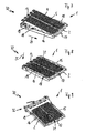
Die in den
Die Zuheizvorrichtung 1 besteht im Wesentlichen aus einem einteiligen Rahmen 2 (siehe insbesondere auch
Radial neben der elektrischen Anschlusseinrichtung 3 sind ein erster Haltearm 7 und ein zweiter Haltearm 8 eines Rahmenkragens 9 angeordnet, mittels welchen die Zuheizvorrichtung 1 an einer Aufnahme eines Heizsystems befestigt werden kann. Beispielsweise kann eine solche Befestigung mittels Schraubverbindungen erzielt werden, wobei entsprechende Schrauben (hier nicht gezeigt) durch Durchgangslöcher 10 bzw. 11 der Haltearme 7 bzw. 8 hindurch geführt sein können.Radially next to the
Um eine elektrische Verbindung zwischen elektrischen Anschlusskontakten 12 der elektrischen Anschlusseinrichtung 3 und elektrischen Kontakten 13 des elektrischen Heizelementes 4 herstellen zu können, sind die elektrischen Anschlusskontakte 12 der elektrischen Anschlusseinrichtung 3 in einen Einlegeraum 14 des einteiligen Rahmens 2 gerichtet.In order to be able to establish an electrical connection between
Der Einlegeraum14 des einteiligen Rahmens 2 ist kopfseitig von dem Rahmenkragen 9, seitlich von Rahmenflanken 15 und 16 und bodenseitig von einem Rahmenboden 17 umgrenzt.The Einlegeraum14 of the one-
Um das elektrische Heizelement 4 dauerhaft und betriebssicher an dem einteiligen Rahmen 2 befestigen und damit auch an der Zuheizvorrichtung 1 halten zu können, umfasst der einteilige Rahmen 2 Haltemittel 18 (siehe insbesondere
Die Haltemittel 18 sind in diesem Ausführungsbeispiel als Rastelemente 19 (hier nur exemplarisch beziffert) realisiert, welche zudem an jeder Rahmenseite mit einem Abstand 20 voneinander beabstandet an dem einteiligen Rahmen 2 angespritzt sind. Somit kann der einteilige Rahmen 2 das elektrische Heizelement 4 punktuell unmittelbar selbst klemmen.The holding means 18 are realized in this embodiment as latching elements 19 (numbered here only by way of example), which are also injection-molded on each frame side at a
Jedes der Rastelemente 19 weist eine Rastnase 21 (siehe insbesondere
Mittels der Rastelemente 19 und insbesondere mittels der Rastnasen 21 kann das elektrische Heizelement 4 gegen eine Auflagekante 22 des einteiligen Rahmens 2 dauerhaft gedrückt werden, insofern ist das elektrische Heizelement 4 sicher zwischen den Rastnasen 21 und der Auflagekante 22 eingeklemmt. Hierbei ragen die Rastnasen 21 und die Auflagekante 22 derart weit in den Einlegeraum 14 hinein, dass selbst eine Radialbewegung 23 des elektrischen Heizelementes 4 keine Gefahr für ein unbeabsichtigtes Lösen des elektrischen Heizelementes 4 aus dem Einlegeraum 14 des einteiligen Rahmens 2 bedeutet.By means of the latching
Beim Zusammenbau der Zuheizvorrichtung 1 wird das elektrische Heizelement 4 mit seinen elektrischen Kontakten 13 voran mit den elektrischen Anschlusskontakten 12 des einteiligen Rahmens 2 in Kontakt gebracht sowie mit einer Axialbewegung 24 axial in Richtung des Rahmenkragens 9 geschoben (siehe
Bei dem in den
Gemäß der Darstellung nach der
Nach der Darstellung der
Bei einem anderen Ausführungsbeispiel 40 einer alternativen Zuheizvorrichtung 1 (siehe beispielsweise
Der einteilige Rahmen 41 ist nach der Darstellung der
Im Bereich des Rahmenbodens 17 des einteiligen Rahmens 2 sind an dem Einlegeraum 14 Haltemittel 18 vorgesehen, in welche jeweils jedes der PTC-Heizelemente 4 einrasten kann.In the region of the
Kopfseitig der Zuheizvorrichtung 1, also im Bereich elektrischer Kontakte 13 der PTC-Heizelemente 4, kann eine Steuereinrichtung (hier nicht gezeigt) auf die Zuheizvorrichtung 1 aufgesteckt werden. Diese Steuereinrichtung kann an seitlichen Außenerhebungen 48 (hier nur exemplarisch beziffert) fixiert werden.At the head end of the
Alle einteiligen Rahmen 2 der vorstehend erläuterten Ausführungsbeispiele sind einstückig hergestellt. Auch die beschriebenen Haltemittel 18 bzw. Rastelemente 19 sind einstückig mit den einteiligen Rahmen 2 ausgebildet, so dass die einteiligen Rahmen 2 einen besonders einfachen Aufbau der jeweiligen elektrischen Zuheizvorrichtung 1 ermöglichen.All one-
Es versteht sich, dass die einteiligen Rahmen 2 mit unterschiedlichen Herstellverfahren hergestellt werden können. Beispielhaft ist in den
Das Spritzgießwerkzeug 50 weist ein Grundwerkzeugteil 51 auf, in welches gemäß erster Einsetzrichtungen 52 ein Formkern 53 in ein Werkzeugfach 54 eingesetzt werden kann. Demzufolge ist das Spritzgießwerkzeug 50 mehrteilig, zumindest jedoch zweiteilig ausgebildet. Gemäß der weiteren Einsetzrichtung 55 können weitere Einsatzteile (hier nicht gezeigt), wie Schieber oder dergleichen, in das Grundwerkzeugteil 51 eingesetzt werden. Insofern können einteilige Rahmen 2 unterschiedlichster Gestalt mit dem vorliegenden Spritzgießwerkzeug 50 gespritzt werden.The
Beispielhaft ist in den
- 11
- Vorrichtung zum elektrischen ZuheizenDevice for electric heating
- 22
- einteiliger Rahmenone-piece frame
- 33
- elektrische Anschlusseinrichtungelectrical connection device
- 44
- elekrisches Heizelementelectrical heating element
- 55
- Heizstäbeheaters
- 66
- Heizrippenheating ribs
- 77
- erster Haltearmfirst holding arm
- 88th
- zweiter Haltearmsecond support arm
- 99
- Rahmenkragenframe collar
- 1010
- erstes Durchgangslochfirst through hole
- 1111
- zweites Durchgangslochsecond through hole
- 1212
- elektrische Anschlusskontakteelectrical connection contacts
- 1313
- elektrische Kontakteelectrical contacts
- 1414
- Einlegerauminsertion space
- 1515
- erste Rahmenflankefirst frame edge
- 1616
- zweite Rahmenflankesecond frame edge
- 1717
- Rahmenbodenframe bottom
- 1818
- Haltemittelholding means
- 1919
- Rastelementelocking elements
- 2020
- Abstanddistance
- 2121
- Rastnasenlocking lugs
- 2222
- Auflagekantesupporting edge
- 2323
- Radialbewegungradial movement
- 2424
- Axialbewegungaxial movement
- 2525
- Abwärtsbewegungdownward movement
- 3030
- weiteres Ausführungsbeispielanother embodiment
- 3131
- Mittelstegcenter web
- 4040
- anderes Ausführungsbeispielanother embodiment
- 4141
- einteiliges Gehäuseone-piece housing
- 4242
- erster Einsteckplatzfirst slot
- 4343
- zweiter Einsteckplatzsecond slot
- 4444
- dritter Einsteckplatzthird slot
- 4545
- Unterseitebottom
- 4646
- Gitterstrukturenlattice structures
- 4747
- EinführrippenEinführrippen
- 4848
- seitliche Außenerhebungenlateral external elevations
- 5050
- Spritzgießwerkzeuginjection mold
- 5151
- GrundwerkzeugteilBasic tool part
- 5252
- erste Einsetzrichtungenfirst Einsetzrichtungen
- 5353
- Formkernmold core
- 5454
- Werkzeugfachtool compartment
- 5555
- weitere Einsetzrichtungfurther insertion direction
Claims (15)
Priority Applications (1)
| Application Number | Priority Date | Filing Date | Title |
|---|---|---|---|
| EP08290538.1A EP2133225B2 (en) | 2008-06-11 | 2008-06-11 | Device for electrical heating in a heating system of a motor vehicle |
Applications Claiming Priority (1)
| Application Number | Priority Date | Filing Date | Title |
|---|---|---|---|
| EP08290538.1A EP2133225B2 (en) | 2008-06-11 | 2008-06-11 | Device for electrical heating in a heating system of a motor vehicle |
Publications (3)
| Publication Number | Publication Date |
|---|---|
| EP2133225A1 true EP2133225A1 (en) | 2009-12-16 |
| EP2133225B1 EP2133225B1 (en) | 2013-11-06 |
| EP2133225B2 EP2133225B2 (en) | 2019-01-23 |
Family
ID=39938158
Family Applications (1)
| Application Number | Title | Priority Date | Filing Date |
|---|---|---|---|
| EP08290538.1A Active EP2133225B2 (en) | 2008-06-11 | 2008-06-11 | Device for electrical heating in a heating system of a motor vehicle |
Country Status (1)
| Country | Link |
|---|---|
| EP (1) | EP2133225B2 (en) |
Cited By (9)
| Publication number | Priority date | Publication date | Assignee | Title |
|---|---|---|---|---|
| CN102529640A (en) * | 2010-10-08 | 2012-07-04 | 埃贝赫卡腾有限两合公司 | Electrical heating device and method for the production thereof |
| FR3032385A1 (en) * | 2015-02-10 | 2016-08-12 | Valeo Systemes Thermiques | HOUSING OF AN ELECTRIC HEATING DEVICE |
| EP3141842A1 (en) * | 2015-09-11 | 2017-03-15 | Mahle International GmbH | Ptc heater for an air conditioning system, in particular of a motor vehicle |
| CN107208930A (en) * | 2015-02-10 | 2017-09-26 | 法雷奥热系统公司 | Electric heater unit and associated locking device |
| DE102016116806A1 (en) | 2016-09-08 | 2018-03-08 | Borgwarner Ludwigsburg Gmbh | air heater |
| FR3056455A1 (en) * | 2016-09-29 | 2018-03-30 | Valeo Systemes Thermiques | FRAME FOR AN ELECTRIC HEATING DEVICE COMPRISING A PLASTIC DEFORMATION MEANS |
| WO2018073530A1 (en) | 2016-10-21 | 2018-04-26 | Valeo Systemes Thermiques | Electric auxiliary heating device |
| WO2019158843A1 (en) * | 2018-02-19 | 2019-08-22 | Valeo Systemes Thermiques | Frame for an electric heating device, comprising at least one elastic device for retaining heating elements |
| FR3078146A1 (en) * | 2018-02-19 | 2019-08-23 | Valeo Systemes Thermiques | FRAME FOR AN ELECTRICAL HEATING DEVICE COMPRISING AT LEAST ONE DEVICE FOR ELASTICALLY HOLDING HEATING ELEMENTS |
Families Citing this family (1)
| Publication number | Priority date | Publication date | Assignee | Title |
|---|---|---|---|---|
| EP3569949B1 (en) | 2018-05-16 | 2020-08-26 | Mahle International GmbH | Heating device comprising a frame for securing a heating element block |
Citations (3)
| Publication number | Priority date | Publication date | Assignee | Title |
|---|---|---|---|---|
| FR2849806A1 (en) * | 2003-01-10 | 2004-07-16 | Valeo Climatisation | Vehicle interior heating device, has air warm up pipe accommodating heat exchanger spaced apart from electric radiator, where radiator is mounted by a support frame with convergent for traversing total flow of warm air to radiator |
| EP1564503A1 (en) * | 2004-02-10 | 2005-08-17 | Catem GmbH & Co. KG | Electical heating device of low height |
| EP1621826A1 (en) * | 2004-07-27 | 2006-02-01 | Behr France Rouffach SAS | Heating arrangement with PTC-Element, in particular for a vehicle |
-
2008
- 2008-06-11 EP EP08290538.1A patent/EP2133225B2/en active Active
Patent Citations (3)
| Publication number | Priority date | Publication date | Assignee | Title |
|---|---|---|---|---|
| FR2849806A1 (en) * | 2003-01-10 | 2004-07-16 | Valeo Climatisation | Vehicle interior heating device, has air warm up pipe accommodating heat exchanger spaced apart from electric radiator, where radiator is mounted by a support frame with convergent for traversing total flow of warm air to radiator |
| EP1564503A1 (en) * | 2004-02-10 | 2005-08-17 | Catem GmbH & Co. KG | Electical heating device of low height |
| EP1621826A1 (en) * | 2004-07-27 | 2006-02-01 | Behr France Rouffach SAS | Heating arrangement with PTC-Element, in particular for a vehicle |
Cited By (16)
| Publication number | Priority date | Publication date | Assignee | Title |
|---|---|---|---|---|
| CN102529640A (en) * | 2010-10-08 | 2012-07-04 | 埃贝赫卡腾有限两合公司 | Electrical heating device and method for the production thereof |
| CN107208930B (en) * | 2015-02-10 | 2020-03-03 | 法雷奥热系统公司 | Electric heating device and associated locking device |
| FR3032385A1 (en) * | 2015-02-10 | 2016-08-12 | Valeo Systemes Thermiques | HOUSING OF AN ELECTRIC HEATING DEVICE |
| WO2016128395A1 (en) * | 2015-02-10 | 2016-08-18 | Valeo Systemes Thermiques | Housing for an electric heating device |
| CN107208930A (en) * | 2015-02-10 | 2017-09-26 | 法雷奥热系统公司 | Electric heater unit and associated locking device |
| CN107206866A (en) * | 2015-02-10 | 2017-09-26 | 法雷奥热系统公司 | The housing of electric heater unit |
| CN107206866B (en) * | 2015-02-10 | 2020-07-07 | 法雷奥热系统公司 | Electric heating device shell |
| EP3141842A1 (en) * | 2015-09-11 | 2017-03-15 | Mahle International GmbH | Ptc heater for an air conditioning system, in particular of a motor vehicle |
| DE102016116806A1 (en) | 2016-09-08 | 2018-03-08 | Borgwarner Ludwigsburg Gmbh | air heater |
| FR3056455A1 (en) * | 2016-09-29 | 2018-03-30 | Valeo Systemes Thermiques | FRAME FOR AN ELECTRIC HEATING DEVICE COMPRISING A PLASTIC DEFORMATION MEANS |
| WO2018073530A1 (en) | 2016-10-21 | 2018-04-26 | Valeo Systemes Thermiques | Electric auxiliary heating device |
| KR20190056403A (en) | 2016-10-21 | 2019-05-24 | 발레오 시스템므 떼르미끄 | Electric auxiliary heating device |
| US11214123B2 (en) | 2016-10-21 | 2022-01-04 | Valeo Systemes Thermiques | Electric auxiliary heating device |
| FR3078146A1 (en) * | 2018-02-19 | 2019-08-23 | Valeo Systemes Thermiques | FRAME FOR AN ELECTRICAL HEATING DEVICE COMPRISING AT LEAST ONE DEVICE FOR ELASTICALLY HOLDING HEATING ELEMENTS |
| FR3078017A1 (en) * | 2018-02-19 | 2019-08-23 | Valeo Systemes Thermiques | FRAME FOR AN ELECTRICAL HEATING DEVICE COMPRISING AT LEAST ONE DEVICE FOR ELASTICALLY HOLDING HEATING ELEMENTS |
| WO2019158843A1 (en) * | 2018-02-19 | 2019-08-22 | Valeo Systemes Thermiques | Frame for an electric heating device, comprising at least one elastic device for retaining heating elements |
Also Published As
| Publication number | Publication date |
|---|---|
| EP2133225B1 (en) | 2013-11-06 |
| EP2133225B2 (en) | 2019-01-23 |
Similar Documents
| Publication | Publication Date | Title |
|---|---|---|
| EP2133225B1 (en) | Device for electrical heating in a heating system of a motor vehicle, and method for production of a frame of an electrical device for heating | |
| DE102006055411B4 (en) | Ventilation, air conditioning or / and heating system with improved ventilation unit | |
| DE202011107805U1 (en) | Seat frame for a vehicle seat | |
| EP0705055A2 (en) | Electrical heating, especially for vehicles | |
| DE102011051310A1 (en) | Additional heater for vehicles | |
| WO2016207302A1 (en) | Air-conditioning system for a vehicle, in particular rooftop air-conditioning system, and vehicle having an air-conditioning system of said type | |
| DE112016000688T5 (en) | Electric heater | |
| EP1621378B2 (en) | Heating device with one heating element, in particular for a vehicle | |
| DE102013000628B4 (en) | Holding frame of a fresh air flap of a motor vehicle and fresh air flap with holding frame | |
| EP1523226B1 (en) | Heating assembly with PTC elements, particularly for motor vehicles | |
| EP2407327A1 (en) | Electric heating device, in particular additional motor vehicle heating and motor vehicle air conditioning device | |
| DE202004020237U1 (en) | Plastic component | |
| DE102014002595B4 (en) | vehicle air conditioning device | |
| EP2125404B1 (en) | Airflow heating device with heating nonwoven fabric | |
| DE102018213759A1 (en) | Rod conductor, stator, electric motor, and method for producing a stator | |
| EP1353131B1 (en) | Electric heater, especially for a vehicle | |
| DE102009057749A1 (en) | Radiator element for heater, has multiple radiator profile segments with two parallel shanks, where middle part forming radiator surface extends between shanks | |
| WO2005026510A1 (en) | Ventilation module | |
| EP2147811B1 (en) | Vehicle air conditioning system with vehicle heating | |
| DE102018105835B3 (en) | Displacement component for at least partially reducing a channel cross-section of a cooling channel in a heat sink for a battery device of a vehicle | |
| EP1486363A1 (en) | Heating arrangement comprising a ptc element, in particular for a vehicle | |
| DE102024000938A1 (en) | Device for cooling a battery of an electrically powered vehicle | |
| DE102008021939A1 (en) | Holding device for connecting components in air conditioning system of motor vehicle, has pin insertable into bracket such that projections are engaged in slot that extends along insertion direction of pin into bracket | |
| EP1652703B2 (en) | Electric heating device for a vehicle | |
| DE10134571A1 (en) | Front element for car's body comprises an elastic clamp having two arms placed at each side of the cable, one arm being part of the radiator's mounting assembly |
Legal Events
| Date | Code | Title | Description |
|---|---|---|---|
| PUAI | Public reference made under article 153(3) epc to a published international application that has entered the european phase |
Free format text: ORIGINAL CODE: 0009012 |
|
| AK | Designated contracting states |
Kind code of ref document: A1 Designated state(s): AT BE BG CH CY CZ DE DK EE ES FI FR GB GR HR HU IE IS IT LI LT LU LV MC MT NL NO PL PT RO SE SI SK TR |
|
| AX | Request for extension of the european patent |
Extension state: AL BA MK RS |
|
| 17P | Request for examination filed |
Effective date: 20100616 |
|
| 17Q | First examination report despatched |
Effective date: 20100707 |
|
| AKX | Designation fees paid |
Designated state(s): AT BE BG CH CY CZ DE DK EE ES FI FR GB GR HR HU IE IS IT LI LT LU LV MC MT NL NO PL PT RO SE SI SK TR |
|
| GRAP | Despatch of communication of intention to grant a patent |
Free format text: ORIGINAL CODE: EPIDOSNIGR1 |
|
| GRAP | Despatch of communication of intention to grant a patent |
Free format text: ORIGINAL CODE: EPIDOSNIGR1 |
|
| INTG | Intention to grant announced |
Effective date: 20130712 |
|
| GRAS | Grant fee paid |
Free format text: ORIGINAL CODE: EPIDOSNIGR3 |
|
| GRAA | (expected) grant |
Free format text: ORIGINAL CODE: 0009210 |
|
| AK | Designated contracting states |
Kind code of ref document: B1 Designated state(s): AT BE BG CH CY CZ DE DK EE ES FI FR GB GR HR HU IE IS IT LI LT LU LV MC MT NL NO PL PT RO SE SI SK TR |
|
| REG | Reference to a national code |
Ref country code: GB Ref legal event code: FG4D Free format text: NOT ENGLISH |
|
| REG | Reference to a national code |
Ref country code: CH Ref legal event code: EP |
|
| REG | Reference to a national code |
Ref country code: AT Ref legal event code: REF Ref document number: 639195 Country of ref document: AT Kind code of ref document: T Effective date: 20131215 |
|
| REG | Reference to a national code |
Ref country code: IE Ref legal event code: FG4D Free format text: LANGUAGE OF EP DOCUMENT: GERMAN |
|
| REG | Reference to a national code |
Ref country code: DE Ref legal event code: R096 Ref document number: 502008010901 Country of ref document: DE Effective date: 20140102 |
|
| REG | Reference to a national code |
Ref country code: NL Ref legal event code: VDEP Effective date: 20131106 |
|
| REG | Reference to a national code |
Ref country code: LT Ref legal event code: MG4D |
|
| PG25 | Lapsed in a contracting state [announced via postgrant information from national office to epo] |
Ref country code: FI Free format text: LAPSE BECAUSE OF FAILURE TO SUBMIT A TRANSLATION OF THE DESCRIPTION OR TO PAY THE FEE WITHIN THE PRESCRIBED TIME-LIMIT Effective date: 20131106 Ref country code: NL Free format text: LAPSE BECAUSE OF FAILURE TO SUBMIT A TRANSLATION OF THE DESCRIPTION OR TO PAY THE FEE WITHIN THE PRESCRIBED TIME-LIMIT Effective date: 20131106 Ref country code: IS Free format text: LAPSE BECAUSE OF FAILURE TO SUBMIT A TRANSLATION OF THE DESCRIPTION OR TO PAY THE FEE WITHIN THE PRESCRIBED TIME-LIMIT Effective date: 20140306 Ref country code: NO Free format text: LAPSE BECAUSE OF FAILURE TO SUBMIT A TRANSLATION OF THE DESCRIPTION OR TO PAY THE FEE WITHIN THE PRESCRIBED TIME-LIMIT Effective date: 20140206 Ref country code: LT Free format text: LAPSE BECAUSE OF FAILURE TO SUBMIT A TRANSLATION OF THE DESCRIPTION OR TO PAY THE FEE WITHIN THE PRESCRIBED TIME-LIMIT Effective date: 20131106 Ref country code: HR Free format text: LAPSE BECAUSE OF FAILURE TO SUBMIT A TRANSLATION OF THE DESCRIPTION OR TO PAY THE FEE WITHIN THE PRESCRIBED TIME-LIMIT Effective date: 20131106 Ref country code: SE Free format text: LAPSE BECAUSE OF FAILURE TO SUBMIT A TRANSLATION OF THE DESCRIPTION OR TO PAY THE FEE WITHIN THE PRESCRIBED TIME-LIMIT Effective date: 20131106 |
|
| PG25 | Lapsed in a contracting state [announced via postgrant information from national office to epo] |
Ref country code: LV Free format text: LAPSE BECAUSE OF FAILURE TO SUBMIT A TRANSLATION OF THE DESCRIPTION OR TO PAY THE FEE WITHIN THE PRESCRIBED TIME-LIMIT Effective date: 20131106 Ref country code: ES Free format text: LAPSE BECAUSE OF FAILURE TO SUBMIT A TRANSLATION OF THE DESCRIPTION OR TO PAY THE FEE WITHIN THE PRESCRIBED TIME-LIMIT Effective date: 20131106 |
|
| PG25 | Lapsed in a contracting state [announced via postgrant information from national office to epo] |
Ref country code: PT Free format text: LAPSE BECAUSE OF FAILURE TO SUBMIT A TRANSLATION OF THE DESCRIPTION OR TO PAY THE FEE WITHIN THE PRESCRIBED TIME-LIMIT Effective date: 20140306 |
|
| PG25 | Lapsed in a contracting state [announced via postgrant information from national office to epo] |
Ref country code: EE Free format text: LAPSE BECAUSE OF FAILURE TO SUBMIT A TRANSLATION OF THE DESCRIPTION OR TO PAY THE FEE WITHIN THE PRESCRIBED TIME-LIMIT Effective date: 20131106 |
|
| REG | Reference to a national code |
Ref country code: DE Ref legal event code: R026 Ref document number: 502008010901 Country of ref document: DE |
|
| PLBI | Opposition filed |
Free format text: ORIGINAL CODE: 0009260 |
|
| PG25 | Lapsed in a contracting state [announced via postgrant information from national office to epo] |
Ref country code: CZ Free format text: LAPSE BECAUSE OF FAILURE TO SUBMIT A TRANSLATION OF THE DESCRIPTION OR TO PAY THE FEE WITHIN THE PRESCRIBED TIME-LIMIT Effective date: 20131106 Ref country code: RO Free format text: LAPSE BECAUSE OF FAILURE TO SUBMIT A TRANSLATION OF THE DESCRIPTION OR TO PAY THE FEE WITHIN THE PRESCRIBED TIME-LIMIT Effective date: 20131106 Ref country code: SK Free format text: LAPSE BECAUSE OF FAILURE TO SUBMIT A TRANSLATION OF THE DESCRIPTION OR TO PAY THE FEE WITHIN THE PRESCRIBED TIME-LIMIT Effective date: 20131106 Ref country code: IT Free format text: LAPSE BECAUSE OF FAILURE TO SUBMIT A TRANSLATION OF THE DESCRIPTION OR TO PAY THE FEE WITHIN THE PRESCRIBED TIME-LIMIT Effective date: 20131106 Ref country code: PL Free format text: LAPSE BECAUSE OF FAILURE TO SUBMIT A TRANSLATION OF THE DESCRIPTION OR TO PAY THE FEE WITHIN THE PRESCRIBED TIME-LIMIT Effective date: 20131106 |
|
| PLAX | Notice of opposition and request to file observation + time limit sent |
Free format text: ORIGINAL CODE: EPIDOSNOBS2 |
|
| 26 | Opposition filed |
Opponent name: VALEO SYSTEMES THERMIQUES Effective date: 20140806 |
|
| PG25 | Lapsed in a contracting state [announced via postgrant information from national office to epo] |
Ref country code: DK Free format text: LAPSE BECAUSE OF FAILURE TO SUBMIT A TRANSLATION OF THE DESCRIPTION OR TO PAY THE FEE WITHIN THE PRESCRIBED TIME-LIMIT Effective date: 20131106 |
|
| REG | Reference to a national code |
Ref country code: DE Ref legal event code: R026 Ref document number: 502008010901 Country of ref document: DE Effective date: 20140806 |
|
| PLAF | Information modified related to communication of a notice of opposition and request to file observations + time limit |
Free format text: ORIGINAL CODE: EPIDOSCOBS2 |
|
| PG25 | Lapsed in a contracting state [announced via postgrant information from national office to epo] |
Ref country code: LU Free format text: LAPSE BECAUSE OF FAILURE TO SUBMIT A TRANSLATION OF THE DESCRIPTION OR TO PAY THE FEE WITHIN THE PRESCRIBED TIME-LIMIT Effective date: 20140611 Ref country code: MC Free format text: LAPSE BECAUSE OF FAILURE TO SUBMIT A TRANSLATION OF THE DESCRIPTION OR TO PAY THE FEE WITHIN THE PRESCRIBED TIME-LIMIT Effective date: 20131106 |
|
| REG | Reference to a national code |
Ref country code: CH Ref legal event code: PL |
|
| GBPC | Gb: european patent ceased through non-payment of renewal fee |
Effective date: 20140611 |
|
| PG25 | Lapsed in a contracting state [announced via postgrant information from national office to epo] |
Ref country code: SI Free format text: LAPSE BECAUSE OF FAILURE TO SUBMIT A TRANSLATION OF THE DESCRIPTION OR TO PAY THE FEE WITHIN THE PRESCRIBED TIME-LIMIT Effective date: 20131106 |
|
| REG | Reference to a national code |
Ref country code: IE Ref legal event code: MM4A |
|
| PLBB | Reply of patent proprietor to notice(s) of opposition received |
Free format text: ORIGINAL CODE: EPIDOSNOBS3 |
|
| PG25 | Lapsed in a contracting state [announced via postgrant information from national office to epo] |
Ref country code: LI Free format text: LAPSE BECAUSE OF NON-PAYMENT OF DUE FEES Effective date: 20140630 Ref country code: IE Free format text: LAPSE BECAUSE OF NON-PAYMENT OF DUE FEES Effective date: 20140611 Ref country code: CH Free format text: LAPSE BECAUSE OF NON-PAYMENT OF DUE FEES Effective date: 20140630 |
|
| RAP2 | Party data changed (patent owner data changed or rights of a patent transferred) |
Owner name: MAHLE BEHR FRANCE ROUFFACH S.A.S |
|
| PG25 | Lapsed in a contracting state [announced via postgrant information from national office to epo] |
Ref country code: GB Free format text: LAPSE BECAUSE OF NON-PAYMENT OF DUE FEES Effective date: 20140611 |
|
| REG | Reference to a national code |
Ref country code: AT Ref legal event code: MM01 Ref document number: 639195 Country of ref document: AT Kind code of ref document: T Effective date: 20140611 |
|
| REG | Reference to a national code |
Ref country code: DE Ref legal event code: R082 Ref document number: 502008010901 Country of ref document: DE Representative=s name: GRAUEL, ANDREAS, DIPL.-PHYS. DR. RER. NAT., DE Ref country code: DE Ref legal event code: R081 Ref document number: 502008010901 Country of ref document: DE Owner name: MAHLE INTERNATIONAL GMBH, DE Free format text: FORMER OWNER: BEHR FRANCE ROUFFACH SAS, ROUFFACH, FR |
|
| PG25 | Lapsed in a contracting state [announced via postgrant information from national office to epo] |
Ref country code: AT Free format text: LAPSE BECAUSE OF NON-PAYMENT OF DUE FEES Effective date: 20140611 |
|
| PG25 | Lapsed in a contracting state [announced via postgrant information from national office to epo] |
Ref country code: MT Free format text: LAPSE BECAUSE OF FAILURE TO SUBMIT A TRANSLATION OF THE DESCRIPTION OR TO PAY THE FEE WITHIN THE PRESCRIBED TIME-LIMIT Effective date: 20131106 |
|
| PG25 | Lapsed in a contracting state [announced via postgrant information from national office to epo] |
Ref country code: BG Free format text: LAPSE BECAUSE OF FAILURE TO SUBMIT A TRANSLATION OF THE DESCRIPTION OR TO PAY THE FEE WITHIN THE PRESCRIBED TIME-LIMIT Effective date: 20131106 |
|
| REG | Reference to a national code |
Ref country code: FR Ref legal event code: PLFP Year of fee payment: 9 |
|
| PG25 | Lapsed in a contracting state [announced via postgrant information from national office to epo] |
Ref country code: CY Free format text: LAPSE BECAUSE OF FAILURE TO SUBMIT A TRANSLATION OF THE DESCRIPTION OR TO PAY THE FEE WITHIN THE PRESCRIBED TIME-LIMIT Effective date: 20131106 Ref country code: GR Free format text: LAPSE BECAUSE OF FAILURE TO SUBMIT A TRANSLATION OF THE DESCRIPTION OR TO PAY THE FEE WITHIN THE PRESCRIBED TIME-LIMIT Effective date: 20140207 |
|
| PG25 | Lapsed in a contracting state [announced via postgrant information from national office to epo] |
Ref country code: TR Free format text: LAPSE BECAUSE OF FAILURE TO SUBMIT A TRANSLATION OF THE DESCRIPTION OR TO PAY THE FEE WITHIN THE PRESCRIBED TIME-LIMIT Effective date: 20131106 Ref country code: BE Free format text: LAPSE BECAUSE OF FAILURE TO SUBMIT A TRANSLATION OF THE DESCRIPTION OR TO PAY THE FEE WITHIN THE PRESCRIBED TIME-LIMIT Effective date: 20140630 Ref country code: HU Free format text: LAPSE BECAUSE OF FAILURE TO SUBMIT A TRANSLATION OF THE DESCRIPTION OR TO PAY THE FEE WITHIN THE PRESCRIBED TIME-LIMIT; INVALID AB INITIO Effective date: 20080611 |
|
| PLAB | Opposition data, opponent's data or that of the opponent's representative modified |
Free format text: ORIGINAL CODE: 0009299OPPO |
|
| APAH | Appeal reference modified |
Free format text: ORIGINAL CODE: EPIDOSCREFNO |
|
| APBM | Appeal reference recorded |
Free format text: ORIGINAL CODE: EPIDOSNREFNO |
|
| APBP | Date of receipt of notice of appeal recorded |
Free format text: ORIGINAL CODE: EPIDOSNNOA2O |
|
| R26 | Opposition filed (corrected) |
Opponent name: VALEO SYSTEMES THERMIQUES Effective date: 20140806 |
|
| APBM | Appeal reference recorded |
Free format text: ORIGINAL CODE: EPIDOSNREFNO |
|
| APBP | Date of receipt of notice of appeal recorded |
Free format text: ORIGINAL CODE: EPIDOSNNOA2O |
|
| APBQ | Date of receipt of statement of grounds of appeal recorded |
Free format text: ORIGINAL CODE: EPIDOSNNOA3O |
|
| REG | Reference to a national code |
Ref country code: FR Ref legal event code: PLFP Year of fee payment: 10 |
|
| APBQ | Date of receipt of statement of grounds of appeal recorded |
Free format text: ORIGINAL CODE: EPIDOSNNOA3O |
|
| REG | Reference to a national code |
Ref country code: FR Ref legal event code: PLFP Year of fee payment: 11 |
|
| PGFP | Annual fee paid to national office [announced via postgrant information from national office to epo] |
Ref country code: FR Payment date: 20180622 Year of fee payment: 11 |
|
| APBU | Appeal procedure closed |
Free format text: ORIGINAL CODE: EPIDOSNNOA9O |
|
| PUAH | Patent maintained in amended form |
Free format text: ORIGINAL CODE: 0009272 |
|
| STAA | Information on the status of an ep patent application or granted ep patent |
Free format text: STATUS: PATENT MAINTAINED AS AMENDED |
|
| 27A | Patent maintained in amended form |
Effective date: 20190123 |
|
| AK | Designated contracting states |
Kind code of ref document: B2 Designated state(s): AT BE BG CH CY CZ DE DK EE ES FI FR GB GR HR HU IE IS IT LI LT LU LV MC MT NL NO PL PT RO SE SI SK TR |
|
| REG | Reference to a national code |
Ref country code: DE Ref legal event code: R102 Ref document number: 502008010901 Country of ref document: DE |
|
| PG25 | Lapsed in a contracting state [announced via postgrant information from national office to epo] |
Ref country code: FR Free format text: LAPSE BECAUSE OF NON-PAYMENT OF DUE FEES Effective date: 20190630 |
|
| P01 | Opt-out of the competence of the unified patent court (upc) registered |
Effective date: 20240527 |
|
| PGFP | Annual fee paid to national office [announced via postgrant information from national office to epo] |
Ref country code: DE Payment date: 20240619 Year of fee payment: 17 |