EP2133139B1 - Cooker comprising a magnetic stirrer - Google Patents
Cooker comprising a magnetic stirrer Download PDFInfo
- Publication number
- EP2133139B1 EP2133139B1 EP09161783A EP09161783A EP2133139B1 EP 2133139 B1 EP2133139 B1 EP 2133139B1 EP 09161783 A EP09161783 A EP 09161783A EP 09161783 A EP09161783 A EP 09161783A EP 2133139 B1 EP2133139 B1 EP 2133139B1
- Authority
- EP
- European Patent Office
- Prior art keywords
- cooker
- mixing tool
- magnetic
- control unit
- cooking pot
- Prior art date
- Legal status (The legal status is an assumption and is not a legal conclusion. Google has not performed a legal analysis and makes no representation as to the accuracy of the status listed.)
- Not-in-force
Links
- 230000005291 magnetic effect Effects 0.000 title claims abstract description 66
- 238000010411 cooking Methods 0.000 claims abstract description 50
- 235000013305 food Nutrition 0.000 claims abstract description 15
- 239000007788 liquid Substances 0.000 claims abstract description 7
- 239000000696 magnetic material Substances 0.000 claims description 5
- 239000000919 ceramic Substances 0.000 claims description 3
- 239000011521 glass Substances 0.000 claims description 3
- 239000002184 metal Substances 0.000 claims description 3
- 239000002907 paramagnetic material Substances 0.000 claims description 2
- 229920000642 polymer Polymers 0.000 claims description 2
- 239000002023 wood Substances 0.000 claims description 2
- 238000003756 stirring Methods 0.000 description 11
- 238000010438 heat treatment Methods 0.000 description 7
- 235000021056 liquid food Nutrition 0.000 description 4
- 239000000463 material Substances 0.000 description 4
- 238000003760 magnetic stirring Methods 0.000 description 2
- 235000011962 puddings Nutrition 0.000 description 2
- 235000014347 soups Nutrition 0.000 description 2
- 230000000694 effects Effects 0.000 description 1
- 230000005611 electricity Effects 0.000 description 1
- 239000012530 fluid Substances 0.000 description 1
- 239000002241 glass-ceramic Substances 0.000 description 1
- 230000006698 induction Effects 0.000 description 1
- 229910001092 metal group alloy Inorganic materials 0.000 description 1
- 238000000034 method Methods 0.000 description 1
- 239000000203 mixture Substances 0.000 description 1
- 230000000737 periodic effect Effects 0.000 description 1
- 230000035699 permeability Effects 0.000 description 1
- 238000006748 scratching Methods 0.000 description 1
- 230000002393 scratching effect Effects 0.000 description 1
- 230000001429 stepping effect Effects 0.000 description 1
- 239000002699 waste material Substances 0.000 description 1
Images

Classifications
-
- A—HUMAN NECESSITIES
- A47—FURNITURE; DOMESTIC ARTICLES OR APPLIANCES; COFFEE MILLS; SPICE MILLS; SUCTION CLEANERS IN GENERAL
- A47J—KITCHEN EQUIPMENT; COFFEE MILLS; SPICE MILLS; APPARATUS FOR MAKING BEVERAGES
- A47J27/00—Cooking-vessels
-
- A—HUMAN NECESSITIES
- A47—FURNITURE; DOMESTIC ARTICLES OR APPLIANCES; COFFEE MILLS; SPICE MILLS; SUCTION CLEANERS IN GENERAL
- A47J—KITCHEN EQUIPMENT; COFFEE MILLS; SPICE MILLS; APPARATUS FOR MAKING BEVERAGES
- A47J43/00—Implements for preparing or holding food, not provided for in other groups of this subclass
- A47J43/04—Machines for domestic use not covered elsewhere, e.g. for grinding, mixing, stirring, kneading, emulsifying, whipping or beating foodstuffs, e.g. power-driven
- A47J43/046—Machines for domestic use not covered elsewhere, e.g. for grinding, mixing, stirring, kneading, emulsifying, whipping or beating foodstuffs, e.g. power-driven with tools driven from the bottom side
- A47J43/0465—Machines for domestic use not covered elsewhere, e.g. for grinding, mixing, stirring, kneading, emulsifying, whipping or beating foodstuffs, e.g. power-driven with tools driven from the bottom side with magnetic drive
-
- B—PERFORMING OPERATIONS; TRANSPORTING
- B01—PHYSICAL OR CHEMICAL PROCESSES OR APPARATUS IN GENERAL
- B01F—MIXING, e.g. DISSOLVING, EMULSIFYING OR DISPERSING
- B01F33/00—Other mixers; Mixing plants; Combinations of mixers
- B01F33/45—Magnetic mixers; Mixers with magnetically driven stirrers
- B01F33/452—Magnetic mixers; Mixers with magnetically driven stirrers using independent floating stirring elements
-
- B—PERFORMING OPERATIONS; TRANSPORTING
- B01—PHYSICAL OR CHEMICAL PROCESSES OR APPARATUS IN GENERAL
- B01F—MIXING, e.g. DISSOLVING, EMULSIFYING OR DISPERSING
- B01F2101/00—Mixing characterised by the nature of the mixed materials or by the application field
- B01F2101/1805—Kitchen, household equipment for mixing
-
- B—PERFORMING OPERATIONS; TRANSPORTING
- B01—PHYSICAL OR CHEMICAL PROCESSES OR APPARATUS IN GENERAL
- B01F—MIXING, e.g. DISSOLVING, EMULSIFYING OR DISPERSING
- B01F27/00—Mixers with rotary stirring devices in fixed receptacles; Kneaders
- B01F27/05—Stirrers
- B01F27/051—Stirrers characterised by their elements, materials or mechanical properties
- B01F27/053—Stirrers characterised by their elements, materials or mechanical properties characterised by their materials
- B01F27/0531—Stirrers characterised by their elements, materials or mechanical properties characterised by their materials with particular surface characteristics, e.g. coated or rough
-
- B—PERFORMING OPERATIONS; TRANSPORTING
- B01—PHYSICAL OR CHEMICAL PROCESSES OR APPARATUS IN GENERAL
- B01F—MIXING, e.g. DISSOLVING, EMULSIFYING OR DISPERSING
- B01F27/00—Mixers with rotary stirring devices in fixed receptacles; Kneaders
- B01F27/05—Stirrers
- B01F27/11—Stirrers characterised by the configuration of the stirrers
- B01F27/116—Stirrers shaped as cylinders, balls or rollers
- B01F27/1162—Balls
Definitions
- This invention is related to magnetic mixers which stir the food without the need of a user to stir the food while cooking liquid foods such as soup and pudding and the cookers in which these mixers are used.
- Liquid foods such as soup and pudding need to be constantly stirred while being cooked.
- the need of the cook to constantly stir the food causes waste of time. Besides, being subjected to heat is an undesirable condition. Therefore magnetic stirring systems have been developed instead of using stirring tools such as spoons and scoops. Thus wasting the time of the cook is prevented and a homogenous stirring is obtained.
- patent application US5549382 discloses an apparatus and a method for automatically stirring food-stuffs in a kitchen environment.
- a stove top comprising a plurality of cooking locations, an agitator device to stir food-stuffs, a driver means for driving said agitator device, a top surface to support a plurality of cooking vessels and a heating means for heating in operable association with each of the cooking locations.
- Said driver means comprises an array of electromagnets placed under cooking locations.
- Said electromagnets are in connection with an actuator which sequentially steps a current through electromagnets.
- said agitator device is pulled to the sequentially energized electromagnets, wherein a stepping action is observed on the agitator device.
- a cooker with automatic stirrer which has a heating unit including a heatproof support provided with an outer side/cooking side and a magnet drive is described.
- the heatproof support is formed to allow a transfer of heat energy from an induction heating device in a direction of a cooking side, where the support is made of a material from a group consisting of a metal, metal alloy, glass, ceramic, glass ceramic and ceran.
- the magnet drive is formed for movement of a magnet-sensitive unit, and the heating device is arranged for operation with gas and/or electricity, where heating power of the heating device is controllable.
- the magnet drive integrated in the hot plate the magnetic stirring member moves and stirs the food-stuffs.
- magnetic field lines pass through the air. Since the resistance of air is high, efficiency to stir food-stuffs will low.
- the mixing operation in the microwave ovens is performed by attaching a U shaped magnet onto the shaft of the motor and then by turning this magnet under the cooking pot.
- the motor turns, the magnet attached to the shaft starts turning.
- a rotating magnetic field is created. This causes the mixing tool in the cooking pot to move.
- the cooker according to the current invention comprises a pot in which the liquid content foods are cooked; cooker grids made of a magnetic material placed on top of the upper cooking plate on which the cooking pot is placed; a burner which provides imprecisely controlled heat for cooking the foods; a control unit connected to an electric supply line; at least two magnetic components wherein a pole of each component is in connection to a grid placed on the upper cooking plate powered by the control unit with cables; and a mixing tool with magnetic properties located in the cooking pot.
- the mixing tool in the cooking pot is pulled by the magnetic component and thus moves.
- coiled fixed magnets are used as the magnetic components, the free ends of the coils are connected to the control unit and the magnetic power of the magnets are turned off by energizing the coils by the control unit and the de-energized coils pull the mixer.
- the mixing tool moves in the cooking pot.
- the object of the invention is to provide a homogeneous stirring of the liquid foods during cooking without intervention of the user.
- Another object of the invention is to mix the liquid in a pot by moving a mixing tool in a cooking pot placed on a cooker by using magnetic components located in a cooker.
- Cooker A
- Cooking pot (1) Mixing tool (2)
- Cooker grids (3)
- Burner (4)
- Cooker upper plate (5)
- Magnetic component (6)
- Control unit (7)
- Fixed magnet (8)
- Cable (11) Coil (12)
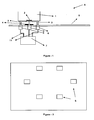
- the cooker (A) of which a schematic side view is given in Figure 1 comprises a pot (1) in which the liquid content foods are cooked; at least one cooker grid (3) made of a magnetic material placed on top of the upper cooking plate (5) on which the cooking pot (1) is placed; gas burner (4) which provides controlled heat to the cooking pot (1) for cooking the foods; the control unit (7) connected to an electric supply line; at least two magnetic components (6) placed on the upper cooking plate (5) powered by the control unit (7) with cables (11) wherein a pole of each component (6) is in connection to a grid (3); and a mixing tool (2) with magnetic properties located in the cooking pot.
- the mixing tool (2) in the cooking pot (1) is pulled by the magnetic component and thus moves in the fluid.
- each control unit (7) is placed under the upper plate (5) of the cooker (A).
- the magnetic components (6) are placed under the cooker upper plate (5) such that they are under the cooking pot (1).
- a pole of each component (6) can be connected to a grid (3).
- each grid (3) is made of a magnetic material.
- the mixing tool (2) continuously rotates in the cooked liquid by periodically energizing the magnetic components (6), creating magnetic poles in these magnetic components (6) as a result of this periodic change and by periodically changing these magnetic poles.
- the magnetic property of the mixing tool (2) causes it to be pulled towards the magnetic field created by the components (6).
- the mixing tool (2) changes location again by the changing magnetic field and this cycle moves the mixing tool (2) and causes it to mix the cooked liquid homogenously.
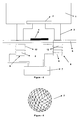
- Electromagnets or coiled (12) fixed magnets (8) showed in Figure 4 can be used as the magnetic components (6).
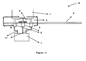
- FIG 3 shows a schematic view of the operation of a sample cooker (A).
- the user puts the cooking pot (1) on the cooker grid (3) placed on the cooker upper plate (5) and places the mixing tool (2) inside the cooking pot (1).
- the control unit (7) is turned on by pressing the mix button on the cooker.
- the control unit (7) which is connected to the power line transfers the electrical current to magnetic components (6) located separately by using cables (11) and simultaneously the electrical energy transforms into magnetic energy creating magnetic field around the components (6).
- the magnetic field lines of the components (6) follow a route from N pole towards S pole. Magnetic field lines created by the components (6) exit from N pole, pass through cooker upper plate (5), cooker grids (3) and cooking pot (1) and affect the mixing tool (2) in the cooking pot (1).
- the magnetic field lines exiting from the mixing tool (2) pass through cooking pot (1), grids (3) and cooker upper plate (5) in order and reach the S pole of the electromagnet (6).
- the magnetic component (6) around which a magnetic field is created pulls the mixing tool (2) towards itself.
- the device (2) moves towards different directions by creating different magnetic fields by the components (6) each time.
- Figure 2 shows a plan view of a sample embodiment about locating the components (6).
- 6 electromagnets (6) are placed under the cooker upper plate (5) such that they form a circle. Electrical current is applied to each of the components (6) placed as described above in a sequential order or these are magnetized differently, therefore the mixing tool (2) starts rotating in the cooking pot (1).
- the mixing tool (2) can be made to follow different paths by changing the arrangement of the electromagnets (6) or by changing the energizing sequence applied by the control unit (7).
- the mixing tool (2) is made of a magnetic material (preferably a material having a high permeability).
- the mixing tool (2) can move easier in the pot (1) since it can be pulled easier by the components (6).
- the mixing tool (2) can be made in a sphere form to provide easier rotation and movement as shown in Figure 5 .
- the sphere can be manufactured with holes on it.
- the mixing tool (2) can be manufactured in different forms such as spiral, triangular or cylindrical. Moreover, the dimensions of the mixing tool (2) can change depending on the amount and viscosity of the food to be mixed.
- the mixing tool (2) can be coated with various materials such as polymers, ceramics, glass or wood. By this way, the undesired high-pitched sounds that can be created by the contact of the mixing tool (2) with the surface of the pot (1) can be prevented. Additionally, depending on the selected material, the mixing speed can be increased as well as minimizing the scratching of the pot surface (1) by the mixing tool (2) (alternatively, the metal coated mixers (2) can be used depending on the need).
- the mixing tool (2) has been shaped like a cross as seen in Figure 6 .
- the magnetic components (6) referenced as A, B, C, D, E and F are magnetized by being energized by the control unit (7).
- the poles of these components (6) are changed very frequently and each change on the poles of the components (6) creates a magnetic field on the device (2), thus causing it to rotate.
- the mixing tool (2) in the cooking pot (1) makes a continuous full rotation.
- the magnetic components (6) referenced as A, B, C, D, E and F increase the rotating force by the aid of the force which pulls the ends of the mixing tool (2) while approaching and pushes while going away. Thus, it gets easier to mix the foods having high density.
- FIG. 4 Another sample embodiment of the invention is shown in Figure 4 .
- the magnets (8) on which the de-energized coils (12) are wound pull the mixing tool (2) in the cooking pot (1) and by continuously energizing different magnets (8) the mixing tool (2) is moved.
- the direction of the magnetic field created during energizing of the coils (12) is arranged such that it will reduce or destroy the effect of the magnetic field created by the fixed magnet (8).
- the circumference of the said magnetic components (6) can be coated with a paramagnetic material.
- a more powerful pulling force can be obtained by making the magnetic field lines more frequent between the poles of such coated components (6) and by increasing the magnetic pulling force. Due to this obtained more powerful pulling force, the rotation of the mixing tool (2) in the cooking pot (2) becomes faster and more effective and it gets easier to mix the foods having a high density.
- the invention can be implemented on each of the burners (4) as well as it can be implemented on a single burner (4). Thus, it becomes possible to mix more than one food at the same time.
- Said burners (4) can be gas or electrical burners.
- the user can start or stop the mixing feature of the cooker (A) with a start-stop knob or button.
- the user can also choose the mixing time and energizing frequency of the magnetic components (6) with a timer and speed setting arrangement connected to the control unit (7) and by this way the user can determine the suitable time and speed for the mixing.
Landscapes
- Engineering & Computer Science (AREA)
- Food Science & Technology (AREA)
- Chemical & Material Sciences (AREA)
- Chemical Kinetics & Catalysis (AREA)
- Mechanical Engineering (AREA)
- Food-Manufacturing Devices (AREA)
- General Preparation And Processing Of Foods (AREA)
Abstract
Description
- This invention is related to magnetic mixers which stir the food without the need of a user to stir the food while cooking liquid foods such as soup and pudding and the cookers in which these mixers are used.
- Liquid foods such as soup and pudding need to be constantly stirred while being cooked. The need of the cook to constantly stir the food causes waste of time. Besides, being subjected to heat is an undesirable condition. Therefore magnetic stirring systems have been developed instead of using stirring tools such as spoons and scoops. Thus wasting the time of the cook is prevented and a homogenous stirring is obtained.
- In the known state of the art, patent application
US5549382 discloses an apparatus and a method for automatically stirring food-stuffs in a kitchen environment. In documentUS5549382 , a stove top comprising a plurality of cooking locations, an agitator device to stir food-stuffs, a driver means for driving said agitator device, a top surface to support a plurality of cooking vessels and a heating means for heating in operable association with each of the cooking locations is disclosed. Said driver means comprises an array of electromagnets placed under cooking locations. Said electromagnets are in connection with an actuator which sequentially steps a current through electromagnets. Thus, said agitator device is pulled to the sequentially energized electromagnets, wherein a stepping action is observed on the agitator device. - In another patent application
DE102006052475 , a cooker with automatic stirrer which has a heating unit including a heatproof support provided with an outer side/cooking side and a magnet drive is described. The heatproof support is formed to allow a transfer of heat energy from an induction heating device in a direction of a cooking side, where the support is made of a material from a group consisting of a metal, metal alloy, glass, ceramic, glass ceramic and ceran. The magnet drive is formed for movement of a magnet-sensitive unit, and the heating device is arranged for operation with gas and/or electricity, where heating power of the heating device is controllable. By the magnet drive integrated in the hot plate, the magnetic stirring member moves and stirs the food-stuffs. In patent applicationDE102006052475 magnetic field lines pass through the air. Since the resistance of air is high, efficiency to stir food-stuffs will low. - In the known state of the art, the system disclosed in patent application
US2006146645 ; the stirring operation is performed by turning an electromagnet placed on a circular panel placed under the cooking plate by the help of a motor and a belt. When the motor turns, the belt causes the circular panel to start turning. Thus the electromagnet on the circular panel starts turning and creates a rotating magnetic field. This causes the mixing tool in the cooking pot to move. However, since the turning motion of the electromagnet is driven by a motor and belt mechanism, the noise of the motor may disturb the user and using a motor increases the costs. - In the patent application
AU1752900 - In the patent application
W09305345 - In the patent application
GB1216736 - The cooker according to the current invention comprises a pot in which the liquid content foods are cooked; cooker grids made of a magnetic material placed on top of the upper cooking plate on which the cooking pot is placed; a burner which provides imprecisely controlled heat for cooking the foods; a control unit connected to an electric supply line; at least two magnetic components wherein a pole of each component is in connection to a grid placed on the upper cooking plate powered by the control unit with cables; and a mixing tool with magnetic properties located in the cooking pot. By sequential energizing of the magnetic components, the mixing tool in the cooking pot is pulled by the magnetic component and thus moves.
- In an alternative embodiment of the invention, coiled fixed magnets are used as the magnetic components, the free ends of the coils are connected to the control unit and the magnetic power of the magnets are turned off by energizing the coils by the control unit and the de-energized coils pull the mixer. Thus, by sequentially energizing of the coils, the mixing tool moves in the cooking pot.
- The object of the invention is to provide a homogeneous stirring of the liquid foods during cooking without intervention of the user.
- Another object of the invention is to mix the liquid in a pot by moving a mixing tool in a cooking pot placed on a cooker by using magnetic components located in a cooker.
- An exemplary cooker of the present invention is illustrated in the annexed drawings in which;
-
Figure 1 is a schematic side view of the cooker. -
Figure 2 is an illustration of how the magnetic components are located. -
Figure 3 is an exemplary schematic view of how the cooker operates. -
Figure 4 is a side view of an alternative embodiment of the invention. -
Figure 5 is a side view of a sample mixer. -
Figure 6 shows the plan view of the mixing tool and the magnetic components in an alternative embodiment of the invention. - The parts in the figures are given individual reference numbers and the corresponding parts are given below.
Cooker (A)
Cooking pot (1)
Mixing tool (2)
Cooker grids (3)
Burner (4)
Cooker upper plate (5)
Magnetic component (6)
Control unit (7)
Fixed magnet (8)
Cable (11)
Coil (12) - The cooker (A) of which a schematic side view is given in
Figure 1 comprises a pot (1) in which the liquid content foods are cooked; at least one cooker grid (3) made of a magnetic material placed on top of the upper cooking plate (5) on which the cooking pot (1) is placed; gas burner (4) which provides controlled heat to the cooking pot (1) for cooking the foods; the control unit (7) connected to an electric supply line; at least two magnetic components (6) placed on the upper cooking plate (5) powered by the control unit (7) with cables (11) wherein a pole of each component (6) is in connection to a grid (3); and a mixing tool (2) with magnetic properties located in the cooking pot. - By sequential energizing of the magnetic components (6) in the cooker (1), the mixing tool (2) in the cooking pot (1) is pulled by the magnetic component and thus moves in the fluid.
- In a sample cooker (A) showed in
Figure 1 , the control unit (7) is placed under the upper plate (5) of the cooker (A). Likewise, the magnetic components (6) are placed under the cooker upper plate (5) such that they are under the cooking pot (1). Also, in order to compress the magnetic field lines created by each magnetic component (6) through the grids (3) under cooking pot (1), a pole of each component (6) can be connected to a grid (3). Thus, each grid (3) is made of a magnetic material. - The mixing tool (2) continuously rotates in the cooked liquid by periodically energizing the magnetic components (6), creating magnetic poles in these magnetic components (6) as a result of this periodic change and by periodically changing these magnetic poles. The magnetic property of the mixing tool (2) causes it to be pulled towards the magnetic field created by the components (6). The mixing tool (2) changes location again by the changing magnetic field and this cycle moves the mixing tool (2) and causes it to mix the cooked liquid homogenously. Electromagnets or coiled (12) fixed magnets (8) showed in
Figure 4 can be used as the magnetic components (6). -
Figure 3 shows a schematic view of the operation of a sample cooker (A). The user puts the cooking pot (1) on the cooker grid (3) placed on the cooker upper plate (5) and places the mixing tool (2) inside the cooking pot (1). The control unit (7) is turned on by pressing the mix button on the cooker. The control unit (7) which is connected to the power line transfers the electrical current to magnetic components (6) located separately by using cables (11) and simultaneously the electrical energy transforms into magnetic energy creating magnetic field around the components (6). The magnetic field lines of the components (6) follow a route from N pole towards S pole. Magnetic field lines created by the components (6) exit from N pole, pass through cooker upper plate (5), cooker grids (3) and cooking pot (1) and affect the mixing tool (2) in the cooking pot (1). Similarly, the magnetic field lines exiting from the mixing tool (2) pass through cooking pot (1), grids (3) and cooker upper plate (5) in order and reach the S pole of the electromagnet (6). Thus, the magnetic component (6) around which a magnetic field is created pulls the mixing tool (2) towards itself. The device (2) moves towards different directions by creating different magnetic fields by the components (6) each time. -
Figure 2 shows a plan view of a sample embodiment about locating the components (6). In this sample embodiment, 6 electromagnets (6) are placed under the cooker upper plate (5) such that they form a circle. Electrical current is applied to each of the components (6) placed as described above in a sequential order or these are magnetized differently, therefore the mixing tool (2) starts rotating in the cooking pot (1). The mixing tool (2) can be made to follow different paths by changing the arrangement of the electromagnets (6) or by changing the energizing sequence applied by the control unit (7). - The mixing tool (2) is made of a magnetic material (preferably a material having a high permeability). The mixing tool (2) can move easier in the pot (1) since it can be pulled easier by the components (6). For example, the mixing tool (2) can be made in a sphere form to provide easier rotation and movement as shown in
Figure 5 . For the liquid food to be mixed better while the sphere is rotating, the sphere can be manufactured with holes on it. - Alternatively, the mixing tool (2) can be manufactured in different forms such as spiral, triangular or cylindrical. Moreover, the dimensions of the mixing tool (2) can change depending on the amount and viscosity of the food to be mixed. The mixing tool (2) can be coated with various materials such as polymers, ceramics, glass or wood. By this way, the undesired high-pitched sounds that can be created by the contact of the mixing tool (2) with the surface of the pot (1) can be prevented. Additionally, depending on the selected material, the mixing speed can be increased as well as minimizing the scratching of the pot surface (1) by the mixing tool (2) (alternatively, the metal coated mixers (2) can be used depending on the need).
- In another embodiment of the invention described above, the mixing tool (2) has been shaped like a cross as seen in
Figure 6 . The magnetic components (6) referenced as A, B, C, D, E and F are magnetized by being energized by the control unit (7). The poles of these components (6) are changed very frequently and each change on the poles of the components (6) creates a magnetic field on the device (2), thus causing it to rotate. By magnetizing the components (6) differently, the mixing tool (2) in the cooking pot (1) makes a continuous full rotation. Moreover, the magnetic components (6) referenced as A, B, C, D, E and F increase the rotating force by the aid of the force which pulls the ends of the mixing tool (2) while approaching and pushes while going away. Thus, it gets easier to mix the foods having high density. - Another sample embodiment of the invention is shown in
Figure 4 . In this embodiment, by using coiled (12) fixed magnets (8) as magnetic components (6), while the magnetic field created by the fixed magnet (8) on which the coil (12) is wound is weakened by the reverse magnetic field of the coil (12), the magnets (8) on which the de-energized coils (12) are wound pull the mixing tool (2) in the cooking pot (1) and by continuously energizing different magnets (8) the mixing tool (2) is moved. The direction of the magnetic field created during energizing of the coils (12) is arranged such that it will reduce or destroy the effect of the magnetic field created by the fixed magnet (8). - The circumference of the said magnetic components (6) can be coated with a paramagnetic material. Thus, a more powerful pulling force can be obtained by making the magnetic field lines more frequent between the poles of such coated components (6) and by increasing the magnetic pulling force. Due to this obtained more powerful pulling force, the rotation of the mixing tool (2) in the cooking pot (2) becomes faster and more effective and it gets easier to mix the foods having a high density.
- The invention can be implemented on each of the burners (4) as well as it can be implemented on a single burner (4). Thus, it becomes possible to mix more than one food at the same time. Said burners (4) can be gas or electrical burners.
- The user can start or stop the mixing feature of the cooker (A) with a start-stop knob or button. The user can also choose the mixing time and energizing frequency of the magnetic components (6) with a timer and speed setting arrangement connected to the control unit (7) and by this way the user can determine the suitable time and speed for the mixing.
Claims (20)
- A cooker (A) that comprises a pot (1) in which the liquid content foods are cooked; at least one cooker grid (3) made of a magnetic material placed on top of the cooker upper plate (5) on which the cooking pot (1) is placed; a burner (4) which provides controlled heat to the cooking pot (1) for cooking the foods; and a mixing tool (2) having magnetic properties located in the cooking pot (1) characterized in that it comprises a control unit (7) connected to an electric supply line; at least two magnetic components (6) placed on the cooker upper plate (5) periodically energized by the control unit with using cables where a pole of each of the magnetic components (6) is in connection with said grid (3) and which moves the said mixing tool (2) by the magnetic field created within.
- A cooker (A) according to Claim 1 characterized in that at least one magnetic component (6) is an electromagnet.
- A cooker (A) according to Claim 1 characterized in that at least one magnetic component is a fixed magnet (8) on which a coil (12) is wound.
- A cooker (A) according to Claim 1 characterized in that at least one magnetic component (6) is coated with a paramagnetic material.
- A cooker (A) according to Claim 1 characterized in that the magnetic components (6) are located under the cooker upper plate (5).
- A cooker (A) according to Claim 5 characterized in that magnetic components (6) are located under the cooking pot (1).
- A cooker (A) according to Claim 1 characterized in that the mixing tool (2) is shaped as a cross.
- A cooker (A) according to Claim 1 characterized in that the mixing tool (2) has a spherical shape.
- A cooker (A) according to Claim 8 characterized in that the mixing tool (2) has a perforated form.
- A cooker (A) according to Claim 1 characterized in that the mixing tool (2) is polymer coated.
- A cooker (A) according to Claim 1 characterized in that the mixing tool (2) is ceramic coated.
- A cooker (A) according to Claim 1 characterized In that the mixing tool (2) is glass coated.
- A cooker (A) according to Claim 1 characterized in that the mixing tool (2) is wood coated.
- A cooker (A) according to Claim 1 characterized in that the mixing tool (2) is metal coated.
- A cooker (A) according to Claim 1 characterized in that the control unit (7) has a start-stop switch setting its operation.
- A cooker (A) according to Claim 1 characterized in that it comprises a timer mechanism in connection with the control unit (7).
- A cooker (A) according to Claim 1 characterized in that it comprises a speed adjustment mechanism in connection with the control unit (7) which determines the energizing frequency of the magnetic components (6).
- A cooker (A) according to Claim 1 characterized in that the cooker burner (4) is a gas burner.
- A cooker (A) according to Claim 1 characterized in that the cooker burner (4) is an electrical burner.
- A cooker (A) according to Claim 1 characterized in that the magnetic components (6) are magnetized differently or same.
Applications Claiming Priority (1)
| Application Number | Priority Date | Filing Date | Title |
|---|---|---|---|
| TR2008/04172A TR200804172A2 (en) | 2008-06-09 | 2008-06-09 | A cooker |
Publications (2)
| Publication Number | Publication Date |
|---|---|
| EP2133139A1 EP2133139A1 (en) | 2009-12-16 |
| EP2133139B1 true EP2133139B1 (en) | 2012-04-18 |
Family
ID=41037669
Family Applications (1)
| Application Number | Title | Priority Date | Filing Date |
|---|---|---|---|
| EP09161783A Not-in-force EP2133139B1 (en) | 2008-06-09 | 2009-06-03 | Cooker comprising a magnetic stirrer |
Country Status (4)
| Country | Link |
|---|---|
| EP (1) | EP2133139B1 (en) |
| AT (1) | ATE553841T1 (en) |
| ES (1) | ES2384016T3 (en) |
| TR (1) | TR200804172A2 (en) |
Cited By (3)
| Publication number | Priority date | Publication date | Assignee | Title |
|---|---|---|---|---|
| CN104651229A (en) * | 2015-02-09 | 2015-05-27 | 山东大学 | Magnetic stirring constant-temperature ventilation incubator |
| US10260036B2 (en) | 2014-10-17 | 2019-04-16 | Sani-Tech West, Inc. | Mixing and filtering system and method |
| US10265667B2 (en) | 2014-03-17 | 2019-04-23 | Sani-Tech West, Inc. | Magnetic mixing system and method |
Families Citing this family (6)
| Publication number | Priority date | Publication date | Assignee | Title |
|---|---|---|---|---|
| ES2383985B1 (en) * | 2010-03-16 | 2013-05-07 | Electrodomésticos Taurus S.L. | KITCHEN CONTAINER WITH ROTATING KNIVES. |
| ES2367281B1 (en) * | 2010-03-16 | 2012-09-04 | Electrodomésticos Taurus S.L. | KITCHEN HOBBY WITH OPERATING MEANS FOR ROTATING BLADES AND KITCHEN HOB ASSEMBLY AND KITCHEN CONTAINER WITH ROTATING BLADES. |
| ES2422933B1 (en) | 2012-01-04 | 2014-07-23 | Compañía Española De Electromenaje, Sl | KITCHEN HOB WITH WEIGHTS |
| ES2590428B1 (en) * | 2015-05-21 | 2017-09-07 | Bsh Electrodomésticos España, S.A. | Cooking battery and cooking system |
| US10028609B2 (en) | 2015-12-30 | 2018-07-24 | Whirlpool Corporation | Vessel for sous vide cooking on an induction cooktop with magnetic stirring and wireless temperature control |
| CN110074648B (en) * | 2018-07-27 | 2025-01-07 | 王伟 | A cooking device |
Family Cites Families (10)
| Publication number | Priority date | Publication date | Assignee | Title |
|---|---|---|---|---|
| FR1570922A (en) | 1967-06-22 | 1969-06-13 | ||
| DE2144372A1 (en) * | 1971-09-04 | 1973-03-15 | Dirk Sijsling | Magnetically driven stirrer - with easily inserted heater between drive and stirrer |
| DE3342249A1 (en) * | 1983-11-23 | 1985-05-30 | Janke & Kunkel GmbH & Co KG Ika - Werk, 7813 Staufen | Magnetic stirrer |
| WO1993005345A1 (en) | 1991-08-28 | 1993-03-18 | Commonwealth Scientific And Industrial Research Organisation | Mixing during microwave or rf heating |
| US5549382A (en) * | 1995-04-27 | 1996-08-27 | Correia, Ii; Bernard A. | Stirrer for food preparation |
| US6076957A (en) | 1999-02-22 | 2000-06-20 | Bel-Art Products, Inc. | Magnetic stirrer adapted for use with microwave ovens |
| DE10111231A1 (en) * | 2001-03-08 | 2002-10-02 | Hte Ag The High Throughput Exp | Method and device for homogeneous mixing of a solid phase in finely divided form with a fluid |
| DE10232886B4 (en) * | 2002-07-19 | 2004-08-12 | Manfred Schmelzer Gmbh | Device for monitoring the operation of magnetic stirrers |
| US20060146645A1 (en) | 2005-01-06 | 2006-07-06 | Rosener William J | MagnaStir |
| DE102006052475A1 (en) * | 2006-11-07 | 2008-05-08 | Vincent Truffault | Kitchen stove for use in cooking system, has heatproof support provided with outer side/cooking side and magnet drive, where support is formed to allow transfer of heat energy from induction heating device in direction of cooking side |
-
2008
- 2008-06-09 TR TR2008/04172A patent/TR200804172A2/en unknown
-
2009
- 2009-06-03 ES ES09161783T patent/ES2384016T3/en active Active
- 2009-06-03 AT AT09161783T patent/ATE553841T1/en active
- 2009-06-03 EP EP09161783A patent/EP2133139B1/en not_active Not-in-force
Cited By (5)
| Publication number | Priority date | Publication date | Assignee | Title |
|---|---|---|---|---|
| US10265667B2 (en) | 2014-03-17 | 2019-04-23 | Sani-Tech West, Inc. | Magnetic mixing system and method |
| US11364475B2 (en) | 2014-03-17 | 2022-06-21 | Sani-Tech West, Inc. | Methods of preparing and using an aseptic mixing system |
| US10260036B2 (en) | 2014-10-17 | 2019-04-16 | Sani-Tech West, Inc. | Mixing and filtering system and method |
| US10501720B2 (en) | 2014-10-17 | 2019-12-10 | Sani-Tech West, Inc. | Mixing and filtering system |
| CN104651229A (en) * | 2015-02-09 | 2015-05-27 | 山东大学 | Magnetic stirring constant-temperature ventilation incubator |
Also Published As
| Publication number | Publication date |
|---|---|
| ES2384016T3 (en) | 2012-06-28 |
| TR200804172A2 (en) | 2009-12-21 |
| ATE553841T1 (en) | 2012-05-15 |
| EP2133139A1 (en) | 2009-12-16 |
Similar Documents
| Publication | Publication Date | Title |
|---|---|---|
| EP2133139A1 (en) | Cooker comprising a magnetic stirrer | |
| US5549382A (en) | Stirrer for food preparation | |
| EP2583750A1 (en) | Kitchen worktop with rotary actuation means and cooking receptacle that can be used with said worktop | |
| JP5677286B2 (en) | Bottle heating and mixing equipment | |
| US10368680B2 (en) | Cookware and geometrically patterned magnetic stirrer assembly | |
| AU2014365235B2 (en) | Combined heating and stirring arrangement method for heating food and heating stirrer | |
| CN100493271C (en) | High-frequency heating apparatus | |
| EP3298860B1 (en) | Cooking utensil | |
| JP2016085862A (en) | Heating and stirring cooker | |
| JP4774074B2 (en) | Electromagnetic induction heater for heating stirrers of various ingredients | |
| EP4122361A1 (en) | Cooking apparatus | |
| CN115916014A (en) | food container | |
| CN115734729A (en) | Food container | |
| CN115734726A (en) | Food container | |
| KR102231776B1 (en) | Cooking device | |
| US20060146645A1 (en) | MagnaStir | |
| WO2022128512A1 (en) | Magnetic stirrer | |
| CN102160760B (en) | Stirrer | |
| KR100316868B1 (en) | Microwave oven | |
| JP2004055507A (en) | Cooking utensil with agitating function | |
| JP3901350B2 (en) | microwave | |
| CN115734728A (en) | Food container | |
| DE102006052475A1 (en) | Kitchen stove for use in cooking system, has heatproof support provided with outer side/cooking side and magnet drive, where support is formed to allow transfer of heat energy from induction heating device in direction of cooking side | |
| JPH04269923A (en) | Rotary cooker | |
| DE20016381U1 (en) | Fully automatic stirring device in hot plates with glass ceramic field |
Legal Events
| Date | Code | Title | Description |
|---|---|---|---|
| PUAI | Public reference made under article 153(3) epc to a published international application that has entered the european phase |
Free format text: ORIGINAL CODE: 0009012 |
|
| AK | Designated contracting states |
Kind code of ref document: A1 Designated state(s): AT BE BG CH CY CZ DE DK EE ES FI FR GB GR HR HU IE IS IT LI LT LU LV MC MK MT NL NO PL PT RO SE SI SK TR |
|
| 17P | Request for examination filed |
Effective date: 20100616 |
|
| 17Q | First examination report despatched |
Effective date: 20110125 |
|
| GRAP | Despatch of communication of intention to grant a patent |
Free format text: ORIGINAL CODE: EPIDOSNIGR1 |
|
| RIC1 | Information provided on ipc code assigned before grant |
Ipc: B01F 13/08 20060101AFI20120111BHEP Ipc: A47J 27/00 20060101ALI20120111BHEP Ipc: B01F 7/00 20060101ALN20120111BHEP Ipc: A47J 43/046 20060101ALI20120111BHEP |
|
| GRAS | Grant fee paid |
Free format text: ORIGINAL CODE: EPIDOSNIGR3 |
|
| GRAA | (expected) grant |
Free format text: ORIGINAL CODE: 0009210 |
|
| AK | Designated contracting states |
Kind code of ref document: B1 Designated state(s): AT BE BG CH CY CZ DE DK EE ES FI FR GB GR HR HU IE IS IT LI LT LU LV MC MK MT NL NO PL PT RO SE SI SK TR |
|
| REG | Reference to a national code |
Ref country code: GB Ref legal event code: FG4D |
|
| REG | Reference to a national code |
Ref country code: CH Ref legal event code: EP |
|
| REG | Reference to a national code |
Ref country code: IE Ref legal event code: FG4D |
|
| REG | Reference to a national code |
Ref country code: AT Ref legal event code: REF Ref document number: 553841 Country of ref document: AT Kind code of ref document: T Effective date: 20120515 |
|
| REG | Reference to a national code |
Ref country code: DE Ref legal event code: R096 Ref document number: 602009006347 Country of ref document: DE Effective date: 20120614 |
|
| REG | Reference to a national code |
Ref country code: ES Ref legal event code: FG2A Ref document number: 2384016 Country of ref document: ES Kind code of ref document: T3 Effective date: 20120628 |
|
| REG | Reference to a national code |
Ref country code: NL Ref legal event code: VDEP Effective date: 20120418 |
|
| REG | Reference to a national code |
Ref country code: AT Ref legal event code: MK05 Ref document number: 553841 Country of ref document: AT Kind code of ref document: T Effective date: 20120418 |
|
| LTIE | Lt: invalidation of european patent or patent extension |
Effective date: 20120418 |
|
| PG25 | Lapsed in a contracting state [announced via postgrant information from national office to epo] |
Ref country code: IS Free format text: LAPSE BECAUSE OF FAILURE TO SUBMIT A TRANSLATION OF THE DESCRIPTION OR TO PAY THE FEE WITHIN THE PRESCRIBED TIME-LIMIT Effective date: 20120818 Ref country code: NO Free format text: LAPSE BECAUSE OF FAILURE TO SUBMIT A TRANSLATION OF THE DESCRIPTION OR TO PAY THE FEE WITHIN THE PRESCRIBED TIME-LIMIT Effective date: 20120718 Ref country code: SE Free format text: LAPSE BECAUSE OF FAILURE TO SUBMIT A TRANSLATION OF THE DESCRIPTION OR TO PAY THE FEE WITHIN THE PRESCRIBED TIME-LIMIT Effective date: 20120418 Ref country code: PL Free format text: LAPSE BECAUSE OF FAILURE TO SUBMIT A TRANSLATION OF THE DESCRIPTION OR TO PAY THE FEE WITHIN THE PRESCRIBED TIME-LIMIT Effective date: 20120418 Ref country code: LT Free format text: LAPSE BECAUSE OF FAILURE TO SUBMIT A TRANSLATION OF THE DESCRIPTION OR TO PAY THE FEE WITHIN THE PRESCRIBED TIME-LIMIT Effective date: 20120418 Ref country code: FI Free format text: LAPSE BECAUSE OF FAILURE TO SUBMIT A TRANSLATION OF THE DESCRIPTION OR TO PAY THE FEE WITHIN THE PRESCRIBED TIME-LIMIT Effective date: 20120418 Ref country code: CY Free format text: LAPSE BECAUSE OF FAILURE TO SUBMIT A TRANSLATION OF THE DESCRIPTION OR TO PAY THE FEE WITHIN THE PRESCRIBED TIME-LIMIT Effective date: 20120418 |
|
| PG25 | Lapsed in a contracting state [announced via postgrant information from national office to epo] |
Ref country code: SI Free format text: LAPSE BECAUSE OF FAILURE TO SUBMIT A TRANSLATION OF THE DESCRIPTION OR TO PAY THE FEE WITHIN THE PRESCRIBED TIME-LIMIT Effective date: 20120418 Ref country code: GR Free format text: LAPSE BECAUSE OF FAILURE TO SUBMIT A TRANSLATION OF THE DESCRIPTION OR TO PAY THE FEE WITHIN THE PRESCRIBED TIME-LIMIT Effective date: 20120719 Ref country code: PT Free format text: LAPSE BECAUSE OF FAILURE TO SUBMIT A TRANSLATION OF THE DESCRIPTION OR TO PAY THE FEE WITHIN THE PRESCRIBED TIME-LIMIT Effective date: 20120820 Ref country code: HR Free format text: LAPSE BECAUSE OF FAILURE TO SUBMIT A TRANSLATION OF THE DESCRIPTION OR TO PAY THE FEE WITHIN THE PRESCRIBED TIME-LIMIT Effective date: 20120418 Ref country code: LV Free format text: LAPSE BECAUSE OF FAILURE TO SUBMIT A TRANSLATION OF THE DESCRIPTION OR TO PAY THE FEE WITHIN THE PRESCRIBED TIME-LIMIT Effective date: 20120418 |
|
| PG25 | Lapsed in a contracting state [announced via postgrant information from national office to epo] |
Ref country code: BE Free format text: LAPSE BECAUSE OF FAILURE TO SUBMIT A TRANSLATION OF THE DESCRIPTION OR TO PAY THE FEE WITHIN THE PRESCRIBED TIME-LIMIT Effective date: 20120418 |
|
| PG25 | Lapsed in a contracting state [announced via postgrant information from national office to epo] |
Ref country code: CZ Free format text: LAPSE BECAUSE OF FAILURE TO SUBMIT A TRANSLATION OF THE DESCRIPTION OR TO PAY THE FEE WITHIN THE PRESCRIBED TIME-LIMIT Effective date: 20120418 Ref country code: EE Free format text: LAPSE BECAUSE OF FAILURE TO SUBMIT A TRANSLATION OF THE DESCRIPTION OR TO PAY THE FEE WITHIN THE PRESCRIBED TIME-LIMIT Effective date: 20120418 Ref country code: MC Free format text: LAPSE BECAUSE OF NON-PAYMENT OF DUE FEES Effective date: 20120630 Ref country code: NL Free format text: LAPSE BECAUSE OF FAILURE TO SUBMIT A TRANSLATION OF THE DESCRIPTION OR TO PAY THE FEE WITHIN THE PRESCRIBED TIME-LIMIT Effective date: 20120418 Ref country code: RO Free format text: LAPSE BECAUSE OF FAILURE TO SUBMIT A TRANSLATION OF THE DESCRIPTION OR TO PAY THE FEE WITHIN THE PRESCRIBED TIME-LIMIT Effective date: 20120418 Ref country code: AT Free format text: LAPSE BECAUSE OF FAILURE TO SUBMIT A TRANSLATION OF THE DESCRIPTION OR TO PAY THE FEE WITHIN THE PRESCRIBED TIME-LIMIT Effective date: 20120418 Ref country code: SK Free format text: LAPSE BECAUSE OF FAILURE TO SUBMIT A TRANSLATION OF THE DESCRIPTION OR TO PAY THE FEE WITHIN THE PRESCRIBED TIME-LIMIT Effective date: 20120418 Ref country code: DK Free format text: LAPSE BECAUSE OF FAILURE TO SUBMIT A TRANSLATION OF THE DESCRIPTION OR TO PAY THE FEE WITHIN THE PRESCRIBED TIME-LIMIT Effective date: 20120418 |
|
| PLBE | No opposition filed within time limit |
Free format text: ORIGINAL CODE: 0009261 |
|
| STAA | Information on the status of an ep patent application or granted ep patent |
Free format text: STATUS: NO OPPOSITION FILED WITHIN TIME LIMIT |
|
| PG25 | Lapsed in a contracting state [announced via postgrant information from national office to epo] |
Ref country code: MK Free format text: LAPSE BECAUSE OF FAILURE TO SUBMIT A TRANSLATION OF THE DESCRIPTION OR TO PAY THE FEE WITHIN THE PRESCRIBED TIME-LIMIT Effective date: 20120418 |
|
| 26N | No opposition filed |
Effective date: 20130121 |
|
| REG | Reference to a national code |
Ref country code: IE Ref legal event code: MM4A |
|
| PG25 | Lapsed in a contracting state [announced via postgrant information from national office to epo] |
Ref country code: IE Free format text: LAPSE BECAUSE OF NON-PAYMENT OF DUE FEES Effective date: 20120603 |
|
| REG | Reference to a national code |
Ref country code: DE Ref legal event code: R097 Ref document number: 602009006347 Country of ref document: DE Effective date: 20130121 |
|
| PG25 | Lapsed in a contracting state [announced via postgrant information from national office to epo] |
Ref country code: BG Free format text: LAPSE BECAUSE OF FAILURE TO SUBMIT A TRANSLATION OF THE DESCRIPTION OR TO PAY THE FEE WITHIN THE PRESCRIBED TIME-LIMIT Effective date: 20120718 Ref country code: MT Free format text: LAPSE BECAUSE OF FAILURE TO SUBMIT A TRANSLATION OF THE DESCRIPTION OR TO PAY THE FEE WITHIN THE PRESCRIBED TIME-LIMIT Effective date: 20120418 |
|
| REG | Reference to a national code |
Ref country code: DE Ref legal event code: R409 Ref document number: 602009006347 Country of ref document: DE |
|
| REG | Reference to a national code |
Ref country code: CH Ref legal event code: PL |
|
| REG | Reference to a national code |
Ref country code: DE Ref legal event code: R119 Ref document number: 602009006347 Country of ref document: DE Effective date: 20140101 |
|
| PG25 | Lapsed in a contracting state [announced via postgrant information from national office to epo] |
Ref country code: DE Free format text: LAPSE BECAUSE OF NON-PAYMENT OF DUE FEES Effective date: 20140101 Ref country code: CH Free format text: LAPSE BECAUSE OF NON-PAYMENT OF DUE FEES Effective date: 20130630 Ref country code: LI Free format text: LAPSE BECAUSE OF NON-PAYMENT OF DUE FEES Effective date: 20130630 |
|
| REG | Reference to a national code |
Ref country code: DE Ref legal event code: R409 Ref document number: 602009006347 Country of ref document: DE |
|
| PG25 | Lapsed in a contracting state [announced via postgrant information from national office to epo] |
Ref country code: LU Free format text: LAPSE BECAUSE OF NON-PAYMENT OF DUE FEES Effective date: 20120603 |
|
| PG25 | Lapsed in a contracting state [announced via postgrant information from national office to epo] |
Ref country code: HU Free format text: LAPSE BECAUSE OF FAILURE TO SUBMIT A TRANSLATION OF THE DESCRIPTION OR TO PAY THE FEE WITHIN THE PRESCRIBED TIME-LIMIT Effective date: 20090603 |
|
| PGRI | Patent reinstated in contracting state [announced from national office to epo] |
Ref country code: DE Effective date: 20140520 |
|
| REG | Reference to a national code |
Ref country code: FR Ref legal event code: PLFP Year of fee payment: 7 |
|
| REG | Reference to a national code |
Ref country code: FR Ref legal event code: PLFP Year of fee payment: 8 |
|
| REG | Reference to a national code |
Ref country code: DE Ref legal event code: R084 Ref document number: 602009006347 Country of ref document: DE |
|
| REG | Reference to a national code |
Ref country code: GB Ref legal event code: 746 Effective date: 20170419 |
|
| REG | Reference to a national code |
Ref country code: FR Ref legal event code: PLFP Year of fee payment: 9 |
|
| REG | Reference to a national code |
Ref country code: ES Ref legal event code: GC2A Effective date: 20180322 |
|
| REG | Reference to a national code |
Ref country code: FR Ref legal event code: PLFP Year of fee payment: 10 |
|
| PGFP | Annual fee paid to national office [announced via postgrant information from national office to epo] |
Ref country code: DE Payment date: 20180625 Year of fee payment: 10 |
|
| PGFP | Annual fee paid to national office [announced via postgrant information from national office to epo] |
Ref country code: TR Payment date: 20180418 Year of fee payment: 10 Ref country code: FR Payment date: 20180620 Year of fee payment: 10 |
|
| PGFP | Annual fee paid to national office [announced via postgrant information from national office to epo] |
Ref country code: IT Payment date: 20180627 Year of fee payment: 10 Ref country code: GB Payment date: 20180620 Year of fee payment: 10 Ref country code: ES Payment date: 20180724 Year of fee payment: 10 |
|
| REG | Reference to a national code |
Ref country code: DE Ref legal event code: R119 Ref document number: 602009006347 Country of ref document: DE |
|
| GBPC | Gb: european patent ceased through non-payment of renewal fee |
Effective date: 20190603 |
|
| PG25 | Lapsed in a contracting state [announced via postgrant information from national office to epo] |
Ref country code: GB Free format text: LAPSE BECAUSE OF NON-PAYMENT OF DUE FEES Effective date: 20190603 Ref country code: IT Free format text: LAPSE BECAUSE OF NON-PAYMENT OF DUE FEES Effective date: 20190603 |
|
| PG25 | Lapsed in a contracting state [announced via postgrant information from national office to epo] |
Ref country code: FR Free format text: LAPSE BECAUSE OF NON-PAYMENT OF DUE FEES Effective date: 20190630 Ref country code: DE Free format text: LAPSE BECAUSE OF NON-PAYMENT OF DUE FEES Effective date: 20200101 |
|
| REG | Reference to a national code |
Ref country code: ES Ref legal event code: FD2A Effective date: 20201027 |
|
| PG25 | Lapsed in a contracting state [announced via postgrant information from national office to epo] |
Ref country code: ES Free format text: LAPSE BECAUSE OF NON-PAYMENT OF DUE FEES Effective date: 20190604 |
|
| PG25 | Lapsed in a contracting state [announced via postgrant information from national office to epo] |
Ref country code: TR Free format text: LAPSE BECAUSE OF NON-PAYMENT OF DUE FEES Effective date: 20190603 |