EP2132456B1 - Pneumatically damping bearing - Google Patents
Pneumatically damping bearing Download PDFInfo
- Publication number
- EP2132456B1 EP2132456B1 EP08717492.6A EP08717492A EP2132456B1 EP 2132456 B1 EP2132456 B1 EP 2132456B1 EP 08717492 A EP08717492 A EP 08717492A EP 2132456 B1 EP2132456 B1 EP 2132456B1
- Authority
- EP
- European Patent Office
- Prior art keywords
- working chamber
- progression element
- housing
- bearing
- chamber
- Prior art date
- Legal status (The legal status is an assumption and is not a legal conclusion. Google has not performed a legal analysis and makes no representation as to the accuracy of the status listed.)
- Not-in-force
Links
Images


Classifications
-
- F—MECHANICAL ENGINEERING; LIGHTING; HEATING; WEAPONS; BLASTING
- F16—ENGINEERING ELEMENTS AND UNITS; GENERAL MEASURES FOR PRODUCING AND MAINTAINING EFFECTIVE FUNCTIONING OF MACHINES OR INSTALLATIONS; THERMAL INSULATION IN GENERAL
- F16F—SPRINGS; SHOCK-ABSORBERS; MEANS FOR DAMPING VIBRATION
- F16F13/00—Units comprising springs of the non-fluid type as well as vibration-dampers, shock-absorbers, or fluid springs
- F16F13/04—Units comprising springs of the non-fluid type as well as vibration-dampers, shock-absorbers, or fluid springs comprising both a plastics spring and a damper, e.g. a friction damper
- F16F13/06—Units comprising springs of the non-fluid type as well as vibration-dampers, shock-absorbers, or fluid springs comprising both a plastics spring and a damper, e.g. a friction damper the damper being a fluid damper, e.g. the plastics spring not forming a part of the wall of the fluid chamber of the damper
- F16F13/20—Units comprising springs of the non-fluid type as well as vibration-dampers, shock-absorbers, or fluid springs comprising both a plastics spring and a damper, e.g. a friction damper the damper being a fluid damper, e.g. the plastics spring not forming a part of the wall of the fluid chamber of the damper characterised by comprising also a pneumatic spring
-
- F—MECHANICAL ENGINEERING; LIGHTING; HEATING; WEAPONS; BLASTING
- F16—ENGINEERING ELEMENTS AND UNITS; GENERAL MEASURES FOR PRODUCING AND MAINTAINING EFFECTIVE FUNCTIONING OF MACHINES OR INSTALLATIONS; THERMAL INSULATION IN GENERAL
- F16F—SPRINGS; SHOCK-ABSORBERS; MEANS FOR DAMPING VIBRATION
- F16F13/00—Units comprising springs of the non-fluid type as well as vibration-dampers, shock-absorbers, or fluid springs
- F16F13/04—Units comprising springs of the non-fluid type as well as vibration-dampers, shock-absorbers, or fluid springs comprising both a plastics spring and a damper, e.g. a friction damper
- F16F13/06—Units comprising springs of the non-fluid type as well as vibration-dampers, shock-absorbers, or fluid springs comprising both a plastics spring and a damper, e.g. a friction damper the damper being a fluid damper, e.g. the plastics spring not forming a part of the wall of the fluid chamber of the damper
- F16F13/08—Units comprising springs of the non-fluid type as well as vibration-dampers, shock-absorbers, or fluid springs comprising both a plastics spring and a damper, e.g. a friction damper the damper being a fluid damper, e.g. the plastics spring not forming a part of the wall of the fluid chamber of the damper the plastics spring forming at least a part of the wall of the fluid chamber of the damper
- F16F13/085—Units comprising springs of the non-fluid type as well as vibration-dampers, shock-absorbers, or fluid springs comprising both a plastics spring and a damper, e.g. a friction damper the damper being a fluid damper, e.g. the plastics spring not forming a part of the wall of the fluid chamber of the damper the plastics spring forming at least a part of the wall of the fluid chamber of the damper characterised by features of plastics springs; Attachment arrangements
Definitions
- the present invention relates to a pneumatic damping bearing, in particular engine mount for motor vehicles, with a suspension spring made of an elastomeric material which supports a bearing core and limits a working chamber, wherein the working chamber with a gas, in particular air, is filled and via a nozzle opening with the environment or connected to another chamber.
- Such a pneumatic damping bearing is made of DE-A 10 2004 008 401 known.
- the suspension spring has a wide, flat, cross-sectional shape in order to achieve a small volume of the working chamber with the largest possible pump cross-section.
- a pneumatic damping bearing having a first elastic member and a second elastic member.
- the second elastic element is accommodated in a cup-shaped bearing housing.
- the first elastic member is in contact with the second elastic member and forms a working chamber.
- the working chamber is connected via an opening in the bearing housing with a compressed air source and also the bearing housing is surrounded by a stopper.
- High-frequency vibrations are damped by the air-filled working chamber and the first and second elastic member.
- the bearing housing moves toward the stopper until the bearing housing abuts against the stopper with its flange. This increases the volume of the working chamber, so that the air pressure in the working chambers is reduced.
- a pneumatic damping bearing having a suspension spring disposed between two plates and forming a working chamber.
- the working chamber is divided by a partition into a first working chamber and a second working chamber.
- a flow opening which connects the two chambers together.
- the suspension spring several openings are introduced, which are connected to the environment.
- Each of the plates protrudes from a tapered pin. High-frequency vibrations are damped only by the working chambers. To damp low-frequency vibrations with large amplitude, the bolts close the flow-through.
- a pneumatic damping bearing forth which includes a suspension spring, which forms a working chamber.
- the suspension spring includes a cup-shaped housing, which has an opening and is limited by a plate. Between the opening and the plate, a spring is inserted, which is connected to a plate-shaped sealing plug, which is provided with an opening. The plug closes the opening to the working chamber.
- a pneumatic spring bearing whose working chamber is bounded on the one hand by the suspension spring and on the other hand by a damper plate.
- a foam layer is applied over the entire surface and glued to it. The foam layer serves to decouple spurious oscillations with small amplitudes.
- a nozzle channel is provided, which connects the working chamber with the environment.
- the invention has for its object to propose a pneumatic damping bearing which avoids the problems described above.
- the required force-displacement curve is generated by the suspension spring and the progression element. If the suspension spring operates around the operating point, the working chamber is compressed between the progression element and the suspension spring. Since the progression element is sufficiently volume-stable due to the elastomeric material used, attenuation occurs during the displacement of air via the nozzle opening provided in the progression element. With increasing, quasi-static loads, the working chamber volume is reduced until it is completely closed and the underside of the suspension spring rests completely against the top of the progression element. Upon further loading, the progression element is elastically deformed. As the load increases further, the quasi-static stiffness increases until finally the maximum travel is achieved. Since the progression element has at least one air chamber on a side facing away from the working chamber, an increased flexibility of the progression element is achieved during its deformation. The ventilation holes introduced into the housing in the area of the air chamber allow the displaced air to escape.
- the air chamber can advantageously have groove-shaped recesses which are formed in the progression element.
- the groove-shaped recesses may be formed, for example, rotationally symmetrical.
- the air chamber is connected via a nozzle opening with the working chamber.
- the nozzle opening acts as a pressure relief valve at high pressures and pressures.
- the progression element is designed as a one-piece vulcanization part.
- the nozzle opening can be introduced in the attachment area.
- the progression element is vulcanized or glued in the housing.
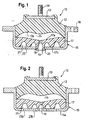
- FIG. 1 shown pneumatic damping bearing 10 is used for storage of an engine, not shown, of a motor vehicle.
- the bearing 10 has a suspension spring 12 made of an elastomeric material, in particular rubber on.
- a bearing core 13 is vulcanized, having a vertically projecting pin 14 for attachment to the engine.
- the suspension spring 12 is supported on its outer periphery of a cup-shaped housing 15, which has a radially projecting flange 16 for fixing to the vehicle body.
- the housing 15, which is presently rotationally symmetrical, but in principle may also have a different cross-sectional shape, has an opening 20 in the middle.
- a progression element 17 made of an elastomeric material is accommodated, which has a fastening flange 19.
- a fastening flange 19 is provided thereon, which is fastened into the housing opening 20.
- the progression element 17 has an upper side 17a which, with the inner side 12a of the suspension spring 12 arranged at a distance therefrom, delimits a working chamber 11.
- the air-filled working chamber 11 is connected via a nozzle opening 18 which penetrates the mounting flange 19, with the environment.
- the progression element 17 has on its side facing away from the working chamber 11 underside 17b an air chamber 21, which is formed by groove-shaped recesses 22. By the air chamber 21, the compliance of the progression element 17 is increased at a pressurization.
- the volume of the working chamber 11 is reduced until it is completely closed and the underside 12 a of the suspension spring 12 bears against the upper side 17 a of the progression element 17.
- this deflection is denoted by z 1 .
- the progression element 17 is compressed, whereby the quasi-static rigidity due to the air chamber 21 increases until finally the maximum path is reached.
- the progression element 17 allows, after closing the working chamber 11, a further deformation of the bearing.
- This in Fig. 2 shown pneumatically damping bearing 10 has a progression element 17 which is accommodated in the housing 15.
- the progression element 17 is fixed to the housing 15 by gluing.
- On the bottom 15 a of the housing 15 a plurality of openings 23 a, 23 b are provided, which connect the air chamber 21 of the progression element 17 with the environment. As a result, a particularly high compliance of the progression element 17 is achieved.
- the progression element 17 an air chamber 21, which via a nozzle opening 24 with the working chamber 11 is connected.
- the nozzle opening 24 acts as a pressure relief valve at high pressures or pressures.
- Fig. 4 shows a further embodiment in which the progression element 17 has a central nozzle opening 18 which communicates with the housing opening 20.
- the nozzle opening is designed as a slotted membrane.
Description
Die vorliegende Erfindung betrifft ein pneumatisch dämpfendes Lager, insbesondere Motorlager für Kraftfahrzeuge, mit einer Tragfeder aus einem elastomeren Material, die einen Lagerkern abstützt und eine Arbeitskammer begrenzt, wobei die Arbeitskammer mit einem Gas, insbesondere Luft, gefüllt ist und über eine Düsenöffnung mit der Umgebung oder mit einer anderen Kammer verbunden ist.The present invention relates to a pneumatic damping bearing, in particular engine mount for motor vehicles, with a suspension spring made of an elastomeric material which supports a bearing core and limits a working chamber, wherein the working chamber with a gas, in particular air, is filled and via a nozzle opening with the environment or connected to another chamber.
Ein derartiges pneumatisch dämpfendes Lager ist aus der
In der
In der
Aus der
Aus der
Motorlager müssen eine Kraft-Weg-Kennlinie erfüllen, um unter bestimmten Lasten noch eine optimale Isolation zu erfüllen. Dies bedeutet, dass die Tragfeder eine große Verformung ermöglichen sollte. Diese Forderung erlaubt jedoch keinen optimalen Einsatz für die Luftdämpfung, da dann das Volumen zu groß wird.Engine mounts must meet a force-displacement curve in order to achieve optimal insulation under certain loads. This means that the suspension spring should allow a large deformation. This requirement allows but not an optimal use for the air damping, because then the volume is too large.
Der Erfindung liegt die Aufgabe zugrunde, ein pneumatisch dämpfendes Lager vorzuschlagen, das die vorstehend beschriebenen Probleme vermeidet.The invention has for its object to propose a pneumatic damping bearing which avoids the problems described above.
Diese Aufgabe wird durch die Merkmale des Anspruchs 1 gelöst. This object is solved by the features of claim 1 .
Bei dem erfindergemäßen Lager wird die geforderte Kraft-Weg-Kennlinie durch die Tragfeder und das Progressionselement generiert. Arbeitet die Tragfeder um den Betriebspunkt wird die Arbeitskammer zwischen dem Progressionselement und der Tragfeder komprimiert. Da das Progressionselement aufgrund des verwendeten elastomeren Materiales ausreichend volumensteif ist, entsteht bei der Verdrängung von Luft über die in dem Progressionselement vorgesehene Düsenöffnung Dämpfung. Bei steigenden, quasistatischen Lasten verringert sich das Arbeitskammervolumen bis es vollständig geschlossen ist und die Unterseite der Tragfeder komplett an der Oberseite des Progressionselementes anliegt. Bei einer weiteren Beaufschlagung wird das Progressionselement elastisch verformt. Bei weiterer Lastzunahme steigt die quasi-statische Steifigkeit, bis schließlich der maximale Weg erreicht ist. Da das Progressionselement an einer der Arbeitskammer abgewandten Seite mindestens eine Luftkammer aufweist, wird eine erhöhte Nachgiebigkeit des Progressionselementes bei dessen Verformung erzielt. Die an dem Gehäuse im Bereich der Luftkammer eingebrachten Entlüftungsbohrungen ermöglichen ein Entweichen der verdrängten Luft.In the inventor bearing the required force-displacement curve is generated by the suspension spring and the progression element. If the suspension spring operates around the operating point, the working chamber is compressed between the progression element and the suspension spring. Since the progression element is sufficiently volume-stable due to the elastomeric material used, attenuation occurs during the displacement of air via the nozzle opening provided in the progression element. With increasing, quasi-static loads, the working chamber volume is reduced until it is completely closed and the underside of the suspension spring rests completely against the top of the progression element. Upon further loading, the progression element is elastically deformed. As the load increases further, the quasi-static stiffness increases until finally the maximum travel is achieved. Since the progression element has at least one air chamber on a side facing away from the working chamber, an increased flexibility of the progression element is achieved during its deformation. The ventilation holes introduced into the housing in the area of the air chamber allow the displaced air to escape.
Vorteilhafte Ausgestaltungen sind Gegenstand der Unteransprüche.Advantageous embodiments are the subject of the dependent claims.
Dabei kann die Luftkammer vorteilhaft rillenförmige Ausnehmungen aufweisen, die in das Progressionselement eingeformt sind. Die rillenförmigen Ausnehmungen können beispielsweise rotationssymmetrisch ausgebildet sein.In this case, the air chamber can advantageously have groove-shaped recesses which are formed in the progression element. The groove-shaped recesses may be formed, for example, rotationally symmetrical.
Vorteilhaft ist die Luftkammer über eine Düsenöffnung mit der Arbeitskammer verbunden. Die Düsenöffnung wirkt als Überdruckventil bei hohen Über- und Unterdrücken.Advantageously, the air chamber is connected via a nozzle opening with the working chamber. The nozzle opening acts as a pressure relief valve at high pressures and pressures.
Bei einer vorteilhaften Ausführungsform ist das Progressionselement als einteiliges Vulkanisationsteil ausgebildet.In an advantageous embodiment, the progression element is designed as a one-piece vulcanization part.
Vorteilhafterweise kann die Düsenöffnung in dem Befestigungsbereich eingebracht sein.Advantageously, the nozzle opening can be introduced in the attachment area.
Bei einer anderen Ausführungsform ist das Progressionselement in dem Gehäuse einvulkanisiert oder eingeklebt.In another embodiment, the progression element is vulcanized or glued in the housing.
Nachfolgend werden Ausführungsformen näher erläutert, die in den Zeichnungen in schematischer Weise dargestellt sind. Hierbei zeigen:
-
Fig. 1 einen Vertikalschnitt durch eine erste Ausführungsform eines Lagers; -
Fig. 2 einen Vertikalschnitt durch eine zweite Ausführungsform eines Lagers; -
Fig. 3 einen Vertikalschnitt durch eine dritte Ausführungsform eines Lagers; -
Fig. 4 einen Vertikalschnitt durch eine vierte Ausführungsform eines Lagers und -
Fig. 5 eine Kraft-Weg-Kennlinie eines erfindungsgemäßen Lagers und der nicht erfindungsgemäßen Ausführungsformen gemäß denFig. 1 bis 4 .
-
Fig. 1 a vertical section through a first embodiment of a bearing; -
Fig. 2 a vertical section through a second embodiment of a bearing; -
Fig. 3 a vertical section through a third embodiment of a bearing; -
Fig. 4 a vertical section through a fourth embodiment of a bearing and -
Fig. 5 a force-displacement characteristic of a bearing according to the invention and the non-inventive embodiments according to theFig. 1 to 4 ,
Die nachfolgenden Ausführungen beziehen sich auf nicht erfindungsgemäße Ausführungsformen, wobei ein erfindungsgemäßes Lager gleiche oder funktionsgleiche Teile verwendet.The following statements relate to non-inventive embodiments, wherein a bearing according to the invention uses the same or functionally identical parts.
Das in
Die Tragfeder 12 stützt sich an ihrem Außenumfang an einen topfförmigen Gehäuse 15 ab, das zur Festlegung an der Fahrzeugkarosserie einen radial abragenden Flansch 16 aufweist. Das Gehäuse 15, das vorliegend rotationssymmetrisch ausgebildet ist, jedoch prinzipiell auch eine andere Querschnittsform aufweisen kann, weist mittig eine Öffnung 20 auf. In dem Gehäuse 20 ist ein Progressionselement 17 aus einem elastomeren Material aufgenommen, das einen Befestigungsflansch 19 aufweist. Zur Festlegung des Progressionselementes 17 ist an diesem ein Befestigungsflansch 19 vorgesehen, der in die Gehäuseöffnung 20 eingeknüpft ist.The
Das Progressionselement 17 weist eine Oberseite 17a auf, die mit der beabstandet hierzu angeordneten Innenseite 12a der Tragfeder 12 eine Arbeitskammer 11 begrenzt. Die mit Luft gefüllte Arbeitskammer 11 ist über eine Düsenöffnung 18, die den Befestigungsflansch 19 durchdringt, mit der Umgebung verbunden.The
Das Progressionselement 17 weist an seiner der Arbeitskammer 11 abgewandten Unterseite 17b eine Luftkammer 21 auf, die durch rillenförmige Ausnehmungen 22 gebildet wird. Durch die Luftkammer 21 wird die Nachgiebigkeit des Progressionselementes 17 bei einer Druckbeaufschlagung erhöht.The
Nachfolgend soll die Funktionsweise des Lagers 10 unter Bezugnahme auf die in
In den
Das in
Bei dem in
Sämtliche vorstehend beschriebenen Ausführungsformen der nicht erfindungsgemäßen Lager und das erfindungsgemäße Lager zeichnen sich dadurch aus, dass durch den Einsatz des Progressionselementes 17 nach Verschließen der Arbeitskammer 11 eine weitere Verformung des Lagers 10 erlaubt wird. Hierbei steigt bei weiterer Lastzunahme die quasi-statische Steifigkeit an, bis schließlich der maximale Weg erreicht ist.All of the above-described embodiments of the bearing not according to the invention and the bearing according to the invention are characterized in that a further deformation of the
Claims (6)
- A pneumatically damping mount (10), in particular an engine mount for motor vehicles, comprising a bearing spring (12) of an elastomeric material supporting a mount core (13) and delimiting a working chamber (11), wherein the working chamber (11) is filled with a gas, in particular air, and communicates with the ambience or another chamber via a nozzle opening (18), wherein a progression element (17) made of an elastomeric material and arranged opposite to the bearing spring (12) and delimiting the working chamber (11) in conjunction with the bearing spring (12), is provided, wherein the bearing spring (12) and the progression element (17) are accommodated in a cup-shaped housing (15), characterized in that the progression element (17) delimits in conjunction with the housing (15) an air chamber (21) at a lower side (17b) facing away from the working chamber, in that the progression element (17) includes an integrally formed mounting flange (19) for snap-fastening at the housing (15), in that venting bores (23a, 23b) are provided at the housing (15) in the area of the air chamber (21), and in that the nozzle opening (18) is provided in the progression element (17).
- The mount according to claim 1, characterized in that the air chamber (21) has groove-like recesses (22) formed into the progression element (17).
- The mount according to any one of the preceding claims, characterized in that the air chamber (21) is in communication with the working chamber (11) via a nozzle opening (24).
- The mount according to any one of the preceding claims, characterized in that the progression element (17) is formed as a one-piece vulcanized part.
- The mount according to any one of the preceding claims, characterized in that the nozzle opening (18) is provided in the mounting flange (19).
- The mount according to any one of the preceding claims, characterized in that the progression element (17) is vulcanized or bonded into the housing (15).
Applications Claiming Priority (2)
| Application Number | Priority Date | Filing Date | Title |
|---|---|---|---|
| DE102007012158A DE102007012158B4 (en) | 2007-03-12 | 2007-03-12 | Pneumatically damping bearing |
| PCT/EP2008/052745 WO2008110506A1 (en) | 2007-03-12 | 2008-03-07 | Pneumatically damping bearing |
Publications (2)
| Publication Number | Publication Date |
|---|---|
| EP2132456A1 EP2132456A1 (en) | 2009-12-16 |
| EP2132456B1 true EP2132456B1 (en) | 2013-06-05 |
Family
ID=39415395
Family Applications (1)
| Application Number | Title | Priority Date | Filing Date |
|---|---|---|---|
| EP08717492.6A Not-in-force EP2132456B1 (en) | 2007-03-12 | 2008-03-07 | Pneumatically damping bearing |
Country Status (10)
| Country | Link |
|---|---|
| US (1) | US8348250B2 (en) |
| EP (1) | EP2132456B1 (en) |
| JP (1) | JP5036832B2 (en) |
| KR (1) | KR101411567B1 (en) |
| CN (1) | CN101646879B (en) |
| BR (1) | BRPI0808850A2 (en) |
| DE (1) | DE102007012158B4 (en) |
| ES (1) | ES2426355T3 (en) |
| IN (1) | IN2009DN05761A (en) |
| WO (1) | WO2008110506A1 (en) |
Cited By (1)
| Publication number | Priority date | Publication date | Assignee | Title |
|---|---|---|---|---|
| DE102018104145B4 (en) * | 2018-02-23 | 2020-10-29 | Dr. Ing. H.C. F. Porsche Aktiengesellschaft | Aggregate bearings |
Families Citing this family (14)
| Publication number | Priority date | Publication date | Assignee | Title |
|---|---|---|---|---|
| WO2006089235A1 (en) | 2005-02-16 | 2006-08-24 | Ferrara Vincent R | Air venting, impact-absorbing compressible members |
| KR101551944B1 (en) | 2010-04-09 | 2015-09-09 | 현대자동차주식회사 | Air damping mount using solenoid valve |
| KR101551952B1 (en) | 2010-09-29 | 2015-09-09 | 현대자동차주식회사 | Air pressure type engine-mount |
| US8950735B2 (en) | 2011-12-14 | 2015-02-10 | Xenith, Llc | Shock absorbers for protective body gear |
| US8814150B2 (en) * | 2011-12-14 | 2014-08-26 | Xenith, Llc | Shock absorbers for protective body gear |
| KR101303562B1 (en) * | 2012-05-04 | 2013-09-09 | 현대자동차주식회사 | Air damping mount |
| CN102691746B (en) * | 2012-06-06 | 2015-04-22 | 宁波拓普集团股份有限公司 | Automotive engine hydraulic suspension device |
| FR2997152B1 (en) * | 2012-10-24 | 2015-01-02 | Anvis Sd France Sas | PNEUMATIC SUPPORT. |
| US8720921B1 (en) * | 2012-10-30 | 2014-05-13 | SuperSprings International, Inc. | Vehicular suspension enhancement |
| FR3049500B1 (en) * | 2016-04-04 | 2018-04-27 | Peugeot Citroen Automobiles Sa | ATTACK PUSH FOR SUSPENDING A VEHICLE HAVING IMPROVED PROGRESSIVITY |
| CN105697648B (en) * | 2016-04-20 | 2017-12-08 | 北汽福田汽车股份有限公司 | A kind of suspending apparatus and vehicle |
| CN111301139B (en) * | 2018-12-11 | 2021-09-21 | 上海汽车集团股份有限公司 | Air suspension assembly and car |
| JP7132961B2 (en) * | 2020-03-02 | 2022-09-07 | 住友理工株式会社 | Anti-vibration device |
| DE102022114323A1 (en) | 2022-06-07 | 2023-12-07 | Vibracoustic Se | Storage system comprising pot and pot bearings as well as pot bearings with locking pins |
Family Cites Families (19)
| Publication number | Priority date | Publication date | Assignee | Title |
|---|---|---|---|---|
| DE546816C (en) * | 1928-09-09 | 1933-12-19 | Isolierrohrwerke Rust & Co Kom | Air cushioning device, especially for the saddle and the handlebars of bicycles and motorcycles |
| DE728501C (en) * | 1941-02-14 | 1942-11-27 | Louis Lege | Air chamber suspension body |
| US3323786A (en) * | 1964-05-06 | 1967-06-06 | Gomma Antivibranti Applic | Resilient suspension system, more particularly for motor vehicle |
| FR1492211A (en) * | 1966-07-05 | 1967-08-18 | Advanced shock absorber | |
| FR2090411A5 (en) * | 1970-02-03 | 1972-01-14 | Pineau Andre | |
| JPS6054537B2 (en) * | 1980-10-09 | 1985-11-30 | 東洋ゴム工業株式会社 | Rubber bearing device with air damping |
| JPS57160716A (en) * | 1981-03-30 | 1982-10-04 | Nissan Motor Co Ltd | Power unit mounting device |
| JPS5931360A (en) | 1982-08-12 | 1984-02-20 | 鹿島建設株式会社 | Vibration-proof support apparatus |
| JPS5934142U (en) * | 1982-08-27 | 1984-03-02 | 株式会社オ−デイオテクニカ | vibration absorber |
| JPS5949040U (en) * | 1982-09-27 | 1984-03-31 | 日産自動車株式会社 | Vibrating body displacement regulating device |
| US4564177A (en) * | 1983-04-21 | 1986-01-14 | The Firestone Tire & Rubber Company | Clamp for non-beaded pneumatic assemblies |
| JPS6147136U (en) * | 1984-08-30 | 1986-03-29 | 日野自動車株式会社 | Automobile engine rubber mounting seat |
| JPH09170636A (en) * | 1995-12-19 | 1997-06-30 | Hokushin Ind Inc | Air damper |
| KR100238397B1 (en) * | 1995-12-31 | 2000-01-15 | 정몽규 | Hydraulic insulator |
| KR200157601Y1 (en) * | 1995-12-31 | 1999-10-01 | 정몽규 | Hydraulic insulator |
| US6199837B1 (en) * | 1998-05-01 | 2001-03-13 | Bridgestone/Firestone, Inc. | Thermoplastic elastomer air spring |
| DE19952638A1 (en) | 1999-10-22 | 2001-04-26 | Wolf Woco & Co Franz J | Spring element with pneumatic dampening for e.g. engine bearing in motor vehicles has working chamber of low height and large surface with damper plate having closed-pore synthetic foam layer |
| DE102004008401A1 (en) | 2004-02-20 | 2005-09-08 | Trelleborg Automotive Technical Centre Gmbh | Pneumatically damping bearing used as an engine bearing for vehicles comprises a working chamber delimited by a bearing spring having a wide flat cross-section and filled with a gas, and a nozzle channel connected to the working chamber |
| DE102004035677B4 (en) * | 2004-07-22 | 2014-02-27 | Carl Freudenberg Kg | Support bearing with at least two interconnected chambers |
-
2007
- 2007-03-12 DE DE102007012158A patent/DE102007012158B4/en not_active Withdrawn - After Issue
-
2008
- 2008-03-07 IN IN5761DEN2009 patent/IN2009DN05761A/en unknown
- 2008-03-07 KR KR1020097019180A patent/KR101411567B1/en active IP Right Grant
- 2008-03-07 JP JP2009553117A patent/JP5036832B2/en not_active Expired - Fee Related
- 2008-03-07 BR BRPI0808850-0A patent/BRPI0808850A2/en not_active IP Right Cessation
- 2008-03-07 ES ES08717492T patent/ES2426355T3/en active Active
- 2008-03-07 CN CN2008800079726A patent/CN101646879B/en not_active Expired - Fee Related
- 2008-03-07 WO PCT/EP2008/052745 patent/WO2008110506A1/en active Application Filing
- 2008-03-07 EP EP08717492.6A patent/EP2132456B1/en not_active Not-in-force
-
2009
- 2009-09-14 US US12/558,621 patent/US8348250B2/en not_active Expired - Fee Related
Cited By (1)
| Publication number | Priority date | Publication date | Assignee | Title |
|---|---|---|---|---|
| DE102018104145B4 (en) * | 2018-02-23 | 2020-10-29 | Dr. Ing. H.C. F. Porsche Aktiengesellschaft | Aggregate bearings |
Also Published As
| Publication number | Publication date |
|---|---|
| BRPI0808850A2 (en) | 2014-09-02 |
| DE102007012158A1 (en) | 2008-09-25 |
| KR20090120488A (en) | 2009-11-24 |
| US8348250B2 (en) | 2013-01-08 |
| EP2132456A1 (en) | 2009-12-16 |
| KR101411567B1 (en) | 2014-06-25 |
| WO2008110506A1 (en) | 2008-09-18 |
| JP2010520982A (en) | 2010-06-17 |
| CN101646879B (en) | 2012-01-04 |
| JP5036832B2 (en) | 2012-09-26 |
| IN2009DN05761A (en) | 2015-07-24 |
| CN101646879A (en) | 2010-02-10 |
| ES2426355T3 (en) | 2013-10-22 |
| DE102007012158B4 (en) | 2009-11-26 |
| US20100025902A1 (en) | 2010-02-04 |
Similar Documents
| Publication | Publication Date | Title |
|---|---|---|
| EP2132456B1 (en) | Pneumatically damping bearing | |
| EP0042910B2 (en) | Mounting with a single hydraulic damping chamber | |
| EP0110195B1 (en) | Engine mounting with two hydraulic damping chambers | |
| EP0134839B1 (en) | Hydraulically damped engine support | |
| DE102015117337A1 (en) | hydromount | |
| EP0042908B1 (en) | Motor mounting for trucks, omnibuses, or the like utility vehicles | |
| DE112009001615T5 (en) | Fluid filled vibration damper | |
| DE102006036343B4 (en) | Damping unit bearing | |
| EP3408558B1 (en) | Hydraulic mount with underpressure valve | |
| DE102015109970B4 (en) | Fluid filled vibration damping device | |
| DE102017007999A1 (en) | Switchable hydraulic bearing | |
| DE19915798C2 (en) | Switchable, hydraulically damping bearing | |
| DE19643170A1 (en) | Hydraulically damped suspension for a power transmission unit | |
| EP1672242B1 (en) | Engine support | |
| DE102014224244A1 (en) | Hydro bearing and motor vehicle with such a hydraulic bearing | |
| DE102015215563B4 (en) | storage facility | |
| DE102014211952A1 (en) | Hydro bearing and motor vehicle with such a hydraulic bearing | |
| WO2018219568A1 (en) | Separation device for separating a working chamber and a compensation chamber of a hydraulically damping bearing, and a hydraulically damping bearing | |
| WO2018141531A1 (en) | Hydromount | |
| DE102013105326B4 (en) | Hydraulic bush | |
| EP2730800B1 (en) | Hydraulic support | |
| DE102014211953A1 (en) | Hydro bearing and motor vehicle with such a hydraulic bearing | |
| DE112021001891T5 (en) | Fluid-filled vibration damping device | |
| DE10117443B4 (en) | Solid bearing | |
| EP3535502B1 (en) | Hydraulically damping mount |
Legal Events
| Date | Code | Title | Description |
|---|---|---|---|
| PUAI | Public reference made under article 153(3) epc to a published international application that has entered the european phase |
Free format text: ORIGINAL CODE: 0009012 |
|
| 17P | Request for examination filed |
Effective date: 20090911 |
|
| AK | Designated contracting states |
Kind code of ref document: A1 Designated state(s): AT BE BG CH CY CZ DE DK EE ES FI FR GB GR HR HU IE IS IT LI LT LU LV MC MT NL NO PL PT RO SE SI SK TR |
|
| DAX | Request for extension of the european patent (deleted) | ||
| 17Q | First examination report despatched |
Effective date: 20110201 |
|
| RAP1 | Party data changed (applicant data changed or rights of an application transferred) |
Owner name: TRELLEBORG AUTOMOTIVE GERMANY GMBH |
|
| GRAP | Despatch of communication of intention to grant a patent |
Free format text: ORIGINAL CODE: EPIDOSNIGR1 |
|
| GRAS | Grant fee paid |
Free format text: ORIGINAL CODE: EPIDOSNIGR3 |
|
| GRAP | Despatch of communication of intention to grant a patent |
Free format text: ORIGINAL CODE: EPIDOSNIGR1 |
|
| GRAA | (expected) grant |
Free format text: ORIGINAL CODE: 0009210 |
|
| AK | Designated contracting states |
Kind code of ref document: B1 Designated state(s): AT BE BG CH CY CZ DE DK EE ES FI FR GB GR HR HU IE IS IT LI LT LU LV MC MT NL NO PL PT RO SE SI SK TR |
|
| REG | Reference to a national code |
Ref country code: GB Ref legal event code: FG4D Free format text: NOT ENGLISH |
|
| REG | Reference to a national code |
Ref country code: CH Ref legal event code: EP |
|
| REG | Reference to a national code |
Ref country code: AT Ref legal event code: REF Ref document number: 615847 Country of ref document: AT Kind code of ref document: T Effective date: 20130615 |
|
| REG | Reference to a national code |
Ref country code: IE Ref legal event code: FG4D Free format text: LANGUAGE OF EP DOCUMENT: GERMAN |
|
| REG | Reference to a national code |
Ref country code: DE Ref legal event code: R096 Ref document number: 502008010072 Country of ref document: DE Effective date: 20130801 |
|
| REG | Reference to a national code |
Ref country code: ES Ref legal event code: FG2A Ref document number: 2426355 Country of ref document: ES Kind code of ref document: T3 Effective date: 20131022 |
|
| PG25 | Lapsed in a contracting state [announced via postgrant information from national office to epo] |
Ref country code: FI Free format text: LAPSE BECAUSE OF FAILURE TO SUBMIT A TRANSLATION OF THE DESCRIPTION OR TO PAY THE FEE WITHIN THE PRESCRIBED TIME-LIMIT Effective date: 20130605 Ref country code: GR Free format text: LAPSE BECAUSE OF FAILURE TO SUBMIT A TRANSLATION OF THE DESCRIPTION OR TO PAY THE FEE WITHIN THE PRESCRIBED TIME-LIMIT Effective date: 20130906 Ref country code: NO Free format text: LAPSE BECAUSE OF FAILURE TO SUBMIT A TRANSLATION OF THE DESCRIPTION OR TO PAY THE FEE WITHIN THE PRESCRIBED TIME-LIMIT Effective date: 20130905 Ref country code: SE Free format text: LAPSE BECAUSE OF FAILURE TO SUBMIT A TRANSLATION OF THE DESCRIPTION OR TO PAY THE FEE WITHIN THE PRESCRIBED TIME-LIMIT Effective date: 20130605 Ref country code: LT Free format text: LAPSE BECAUSE OF FAILURE TO SUBMIT A TRANSLATION OF THE DESCRIPTION OR TO PAY THE FEE WITHIN THE PRESCRIBED TIME-LIMIT Effective date: 20130605 Ref country code: SI Free format text: LAPSE BECAUSE OF FAILURE TO SUBMIT A TRANSLATION OF THE DESCRIPTION OR TO PAY THE FEE WITHIN THE PRESCRIBED TIME-LIMIT Effective date: 20130605 |
|
| REG | Reference to a national code |
Ref country code: NL Ref legal event code: VDEP Effective date: 20130605 |
|
| REG | Reference to a national code |
Ref country code: LT Ref legal event code: MG4D |
|
| PG25 | Lapsed in a contracting state [announced via postgrant information from national office to epo] |
Ref country code: BG Free format text: LAPSE BECAUSE OF FAILURE TO SUBMIT A TRANSLATION OF THE DESCRIPTION OR TO PAY THE FEE WITHIN THE PRESCRIBED TIME-LIMIT Effective date: 20130905 Ref country code: PL Free format text: LAPSE BECAUSE OF FAILURE TO SUBMIT A TRANSLATION OF THE DESCRIPTION OR TO PAY THE FEE WITHIN THE PRESCRIBED TIME-LIMIT Effective date: 20130605 Ref country code: HR Free format text: LAPSE BECAUSE OF FAILURE TO SUBMIT A TRANSLATION OF THE DESCRIPTION OR TO PAY THE FEE WITHIN THE PRESCRIBED TIME-LIMIT Effective date: 20130605 |
|
| PG25 | Lapsed in a contracting state [announced via postgrant information from national office to epo] |
Ref country code: LV Free format text: LAPSE BECAUSE OF FAILURE TO SUBMIT A TRANSLATION OF THE DESCRIPTION OR TO PAY THE FEE WITHIN THE PRESCRIBED TIME-LIMIT Effective date: 20130605 |
|
| PG25 | Lapsed in a contracting state [announced via postgrant information from national office to epo] |
Ref country code: CZ Free format text: LAPSE BECAUSE OF FAILURE TO SUBMIT A TRANSLATION OF THE DESCRIPTION OR TO PAY THE FEE WITHIN THE PRESCRIBED TIME-LIMIT Effective date: 20130605 Ref country code: EE Free format text: LAPSE BECAUSE OF FAILURE TO SUBMIT A TRANSLATION OF THE DESCRIPTION OR TO PAY THE FEE WITHIN THE PRESCRIBED TIME-LIMIT Effective date: 20130605 Ref country code: PT Free format text: LAPSE BECAUSE OF FAILURE TO SUBMIT A TRANSLATION OF THE DESCRIPTION OR TO PAY THE FEE WITHIN THE PRESCRIBED TIME-LIMIT Effective date: 20131007 Ref country code: IS Free format text: LAPSE BECAUSE OF FAILURE TO SUBMIT A TRANSLATION OF THE DESCRIPTION OR TO PAY THE FEE WITHIN THE PRESCRIBED TIME-LIMIT Effective date: 20131005 Ref country code: SK Free format text: LAPSE BECAUSE OF FAILURE TO SUBMIT A TRANSLATION OF THE DESCRIPTION OR TO PAY THE FEE WITHIN THE PRESCRIBED TIME-LIMIT Effective date: 20130605 |
|
| PG25 | Lapsed in a contracting state [announced via postgrant information from national office to epo] |
Ref country code: RO Free format text: LAPSE BECAUSE OF FAILURE TO SUBMIT A TRANSLATION OF THE DESCRIPTION OR TO PAY THE FEE WITHIN THE PRESCRIBED TIME-LIMIT Effective date: 20130605 Ref country code: NL Free format text: LAPSE BECAUSE OF FAILURE TO SUBMIT A TRANSLATION OF THE DESCRIPTION OR TO PAY THE FEE WITHIN THE PRESCRIBED TIME-LIMIT Effective date: 20130605 |
|
| PLBE | No opposition filed within time limit |
Free format text: ORIGINAL CODE: 0009261 |
|
| STAA | Information on the status of an ep patent application or granted ep patent |
Free format text: STATUS: NO OPPOSITION FILED WITHIN TIME LIMIT |
|
| PG25 | Lapsed in a contracting state [announced via postgrant information from national office to epo] |
Ref country code: DK Free format text: LAPSE BECAUSE OF FAILURE TO SUBMIT A TRANSLATION OF THE DESCRIPTION OR TO PAY THE FEE WITHIN THE PRESCRIBED TIME-LIMIT Effective date: 20130605 |
|
| 26N | No opposition filed |
Effective date: 20140306 |
|
| PG25 | Lapsed in a contracting state [announced via postgrant information from national office to epo] |
Ref country code: IT Free format text: LAPSE BECAUSE OF FAILURE TO SUBMIT A TRANSLATION OF THE DESCRIPTION OR TO PAY THE FEE WITHIN THE PRESCRIBED TIME-LIMIT Effective date: 20130605 |
|
| REG | Reference to a national code |
Ref country code: DE Ref legal event code: R097 Ref document number: 502008010072 Country of ref document: DE Effective date: 20140306 |
|
| PG25 | Lapsed in a contracting state [announced via postgrant information from national office to epo] |
Ref country code: LU Free format text: LAPSE BECAUSE OF FAILURE TO SUBMIT A TRANSLATION OF THE DESCRIPTION OR TO PAY THE FEE WITHIN THE PRESCRIBED TIME-LIMIT Effective date: 20140307 |
|
| REG | Reference to a national code |
Ref country code: CH Ref legal event code: PL |
|
| GBPC | Gb: european patent ceased through non-payment of renewal fee |
Effective date: 20140307 |
|
| REG | Reference to a national code |
Ref country code: IE Ref legal event code: MM4A |
|
| PG25 | Lapsed in a contracting state [announced via postgrant information from national office to epo] |
Ref country code: LI Free format text: LAPSE BECAUSE OF NON-PAYMENT OF DUE FEES Effective date: 20140331 Ref country code: CH Free format text: LAPSE BECAUSE OF NON-PAYMENT OF DUE FEES Effective date: 20140331 Ref country code: GB Free format text: LAPSE BECAUSE OF NON-PAYMENT OF DUE FEES Effective date: 20140307 Ref country code: IE Free format text: LAPSE BECAUSE OF NON-PAYMENT OF DUE FEES Effective date: 20140307 |
|
| REG | Reference to a national code |
Ref country code: AT Ref legal event code: MM01 Ref document number: 615847 Country of ref document: AT Kind code of ref document: T Effective date: 20140307 |
|
| PG25 | Lapsed in a contracting state [announced via postgrant information from national office to epo] |
Ref country code: AT Free format text: LAPSE BECAUSE OF NON-PAYMENT OF DUE FEES Effective date: 20140307 |
|
| PG25 | Lapsed in a contracting state [announced via postgrant information from national office to epo] |
Ref country code: MT Free format text: LAPSE BECAUSE OF FAILURE TO SUBMIT A TRANSLATION OF THE DESCRIPTION OR TO PAY THE FEE WITHIN THE PRESCRIBED TIME-LIMIT Effective date: 20130605 |
|
| REG | Reference to a national code |
Ref country code: FR Ref legal event code: PLFP Year of fee payment: 9 |
|
| PG25 | Lapsed in a contracting state [announced via postgrant information from national office to epo] |
Ref country code: MC Free format text: LAPSE BECAUSE OF FAILURE TO SUBMIT A TRANSLATION OF THE DESCRIPTION OR TO PAY THE FEE WITHIN THE PRESCRIBED TIME-LIMIT Effective date: 20130605 |
|
| PG25 | Lapsed in a contracting state [announced via postgrant information from national office to epo] |
Ref country code: CY Free format text: LAPSE BECAUSE OF FAILURE TO SUBMIT A TRANSLATION OF THE DESCRIPTION OR TO PAY THE FEE WITHIN THE PRESCRIBED TIME-LIMIT Effective date: 20130605 |
|
| PG25 | Lapsed in a contracting state [announced via postgrant information from national office to epo] |
Ref country code: BE Free format text: LAPSE BECAUSE OF FAILURE TO SUBMIT A TRANSLATION OF THE DESCRIPTION OR TO PAY THE FEE WITHIN THE PRESCRIBED TIME-LIMIT Effective date: 20140331 Ref country code: HU Free format text: LAPSE BECAUSE OF FAILURE TO SUBMIT A TRANSLATION OF THE DESCRIPTION OR TO PAY THE FEE WITHIN THE PRESCRIBED TIME-LIMIT; INVALID AB INITIO Effective date: 20080307 |
|
| REG | Reference to a national code |
Ref country code: FR Ref legal event code: PLFP Year of fee payment: 10 |
|
| REG | Reference to a national code |
Ref country code: FR Ref legal event code: PLFP Year of fee payment: 11 |
|
| PGFP | Annual fee paid to national office [announced via postgrant information from national office to epo] |
Ref country code: FR Payment date: 20180326 Year of fee payment: 11 Ref country code: TR Payment date: 20180306 Year of fee payment: 11 |
|
| PGFP | Annual fee paid to national office [announced via postgrant information from national office to epo] |
Ref country code: ES Payment date: 20180423 Year of fee payment: 11 |
|
| PG25 | Lapsed in a contracting state [announced via postgrant information from national office to epo] |
Ref country code: FR Free format text: LAPSE BECAUSE OF NON-PAYMENT OF DUE FEES Effective date: 20190331 |
|
| REG | Reference to a national code |
Ref country code: DE Ref legal event code: R082 Ref document number: 502008010072 Country of ref document: DE Representative=s name: PATENTANWAELTE OLBRICHT, BUCHHOLD, KEULERTZ PA, DE |
|
| REG | Reference to a national code |
Ref country code: ES Ref legal event code: FD2A Effective date: 20200724 |
|
| PGFP | Annual fee paid to national office [announced via postgrant information from national office to epo] |
Ref country code: DE Payment date: 20200409 Year of fee payment: 13 |
|
| PG25 | Lapsed in a contracting state [announced via postgrant information from national office to epo] |
Ref country code: ES Free format text: LAPSE BECAUSE OF NON-PAYMENT OF DUE FEES Effective date: 20190308 |
|
| REG | Reference to a national code |
Ref country code: DE Ref legal event code: R119 Ref document number: 502008010072 Country of ref document: DE |
|
| PG25 | Lapsed in a contracting state [announced via postgrant information from national office to epo] |
Ref country code: DE Free format text: LAPSE BECAUSE OF NON-PAYMENT OF DUE FEES Effective date: 20211001 |
|
| PG25 | Lapsed in a contracting state [announced via postgrant information from national office to epo] |
Ref country code: TR Free format text: LAPSE BECAUSE OF NON-PAYMENT OF DUE FEES Effective date: 20190307 |