EP2132448B1 - Component joining - Google Patents
Component joining Download PDFInfo
- Publication number
- EP2132448B1 EP2132448B1 EP08718596.3A EP08718596A EP2132448B1 EP 2132448 B1 EP2132448 B1 EP 2132448B1 EP 08718596 A EP08718596 A EP 08718596A EP 2132448 B1 EP2132448 B1 EP 2132448B1
- Authority
- EP
- European Patent Office
- Prior art keywords
- ductile sheet
- threaded
- nut
- ductile
- component
- Prior art date
- Legal status (The legal status is an assumption and is not a legal conclusion. Google has not performed a legal analysis and makes no representation as to the accuracy of the status listed.)
- Not-in-force
Links
Images





Classifications
-
- F—MECHANICAL ENGINEERING; LIGHTING; HEATING; WEAPONS; BLASTING
- F16—ENGINEERING ELEMENTS AND UNITS; GENERAL MEASURES FOR PRODUCING AND MAINTAINING EFFECTIVE FUNCTIONING OF MACHINES OR INSTALLATIONS; THERMAL INSULATION IN GENERAL
- F16B—DEVICES FOR FASTENING OR SECURING CONSTRUCTIONAL ELEMENTS OR MACHINE PARTS TOGETHER, e.g. NAILS, BOLTS, CIRCLIPS, CLAMPS, CLIPS OR WEDGES; JOINTS OR JOINTING
- F16B5/00—Joining sheets or plates, e.g. panels, to one another or to strips or bars parallel to them
- F16B5/02—Joining sheets or plates, e.g. panels, to one another or to strips or bars parallel to them by means of fastening members using screw-thread
- F16B5/0291—Joining sheets or plates, e.g. panels, to one another or to strips or bars parallel to them by means of fastening members using screw-thread the threaded element being driven through the edge of a sheet plate with its axis in the plane of the plate
-
- Y—GENERAL TAGGING OF NEW TECHNOLOGICAL DEVELOPMENTS; GENERAL TAGGING OF CROSS-SECTIONAL TECHNOLOGIES SPANNING OVER SEVERAL SECTIONS OF THE IPC; TECHNICAL SUBJECTS COVERED BY FORMER USPC CROSS-REFERENCE ART COLLECTIONS [XRACs] AND DIGESTS
- Y10—TECHNICAL SUBJECTS COVERED BY FORMER USPC
- Y10T—TECHNICAL SUBJECTS COVERED BY FORMER US CLASSIFICATION
- Y10T403/00—Joints and connections
- Y10T403/71—Rod side to plate or side
- Y10T403/7123—Traversed by connector
Definitions
- the present invention relates to component joining.
- embodiments of the invention relate to a ductile sheet for securing to a component and to a jointed arrangement comprising first and second ductile sheets secured together.
- Embodiments of the invention also relate to a method for securing a first ductile sheet to a second ductile sheet.
- a system for joining panels according to the preamble of claim 1 is known from US 3 498 655 A .
- ductile sheets it is desirable to be able to secure ductile sheets together such that their respective planes are generally perpendicular, whereby the ductile sheets define a T-joint, and there is often a requirement that one of the ductile sheets, which may act as a cover plate, presents a flat surface with no components projecting above the plane of the outer surface of the cover plate.
- one method of securing ductile sheets together to form a T-joint is to use a welded joint in which a fillet weld 10 is used to secure two ductile sheets 12, 14 together.
- welding is a complex operation requiring specialised equipment. Heat created by welding can also distort the ductile sheets 12, 14 and possibly affect their material properties and, furthermore, the resultant welded joint is permanent meaning that the ductile sheets 12, 14 cannot be easily disassembled.
- FIG. 2 Another method of securing ductile sheets together to form a T-joint is shown in Fig. 2 .
- a retention bar 16 is located in an aperture in an anchor plate 18, and opposite ends of the retention bar 16 are secured to a cover plate 20 using threaded fasteners 22.
- countersunk apertures 24 must be formed in the cover plate 20.
- the cover plate 20 must be sufficiently thick to accommodate the heads of the countersunk threaded fasteners 22, and this adds cost and weight to the resultant joint.
- Countersunk apertures 24 must be formed in the cover plate 20, and this additional operation requires additional tooling, thus increasing cost and lead-time.
- the requirement for two nuts and threaded fasteners 22 and the retention bar 16 increases cost, weight and assembly time.
- Another problem is that the retention bar 16 can distort during tightening of the threaded fasteners 22.
- a jointed arrangement comprising a first ductile sheet and a component, wherein the first ductile sheet includes an aperture for receiving a threaded fastener, the fastener engaging a threaded nut to secure the ductile sheet to the component, characterised in that the ductile sheet includes a deformable region in which the aperture is defined whereby the deformable region is deformable out of the plane of the ductile sheet during tightening of the threaded fastener to secure the ductile sheet to the component.
- the component may include a recess in which the deformable region of the first ductile sheet is received following tightening of the threaded fastener to secure the first ductile sheet to the second ductile sheet.
- the component includes a passage, extending from the recess for receiving a threaded shank of the threaded fastener.
- the passage may include a nut receiving portion for receiving the threaded nut in which the threaded shank of the threaded fastener is locatable to thereby secure the first ductile sheet to the component.
- the nut receiving portion may include an anti-rotation region which is operable to prevent rotation of the threaded nut during rotation of the threaded shank of the threaded fastener relative to the threaded nut.
- the edges of the passage may be tapered to define the anti-rotation region.
- the edges of the passage may include inwardly directed projections to define the anti-rotation region.
- the component may include apertures substantially adjacent to the inwardly directed projections to permit localised deformation of the second ductile sheet.
- the component includes a nut retaining member which is locatable in an aperture of the threaded nut to retain the nut in the nut receiving portion prior to insertion of the threaded shank of the threaded fastener into the aperture of the threaded nut.
- the nut retaining member is displaceable out of the aperture of the threaded nut by the threaded shank of the threaded fastener during tightening rotation of the threaded fastener.
- the first ductile sheet includes at least one locating recess and the component includes at least one complementary locating projection.
- the component is in the form of a second ductile sheet to which the first ductile sheet (32, 132) is secured, wherein the first ductile sheet is secured along an edge of the second ductile sheet such that the planes of the first and second ductile sheets are generally perpendicular.
- the aperture in the first ductile sheet is defined substantially centrally in the deformable region.
- the aperture may be defined by an annular member.
- the deformable region may comprises a plurality of deformable ribs extending between the ductile sheet and the annular member to support the annular member and enable its deformation out of the plane of the ductile sheet during tightening of the threaded fastener.
- the deformable ribs are in the form of spokes.
- the deformable ribs may be of generally helical or spiral configuration.
- a method for securing a first ductile sheet along an edge of a second ductile sheet with the planes of the first and second ductile sheets generally perpendicular, the first ductile sheet including a deformable region in which an aperture is defined comprising locating a threaded fastener in the aperture and causing engagement of the threaded fastener with a threaded formation of the second ductile sheet, and rotating the threaded fastener to tighten it such that tightening rotation of the threaded fastener deforms the deformable region out of the plane of the first ductile sheet and into a recess defined in the second ductile sheet.
- the method may comprise rotating the threaded fastener to deform the deformable region such that a head of the threaded fastener may be substantially coplanar with the plane of the first ductile sheet following deformation of the deformable region.
- the method may comprise rotating the threaded fastener to deform the deformable region such that a head of the threaded fastener may extend partially into the recess in the second ductile sheet following deformation of the deformable region.
- a jointed arrangement 30 in which a first ductile sheet 32 is secured to a component 34 in the form of a second ductile sheet 36.
- the first ductile sheet 32 is secured along an edge 38 of the second ductile sheet 36 in such a way that respective planes X-X and Y-Y of the first and second ductile sheets 32, 36 are generally perpendicular.
- the resulting joint thereby defined between the first and second ductile sheets 32, 36 is a T-joint.
- the first ductile sheet 32 includes a deformable region 42 in substantially the centre of which is located an aperture 40.
- the deformable region 42 generally comprises a plurality of deformable ribs 44 extending between the first ductile sheet 32 and the aperture 40 which is defined by a generally annular ring member 46.
- the deformable ribs 44 are in the form of spokes 48.
- the deformable ribs 44 and the annular member 46 defining the aperture 40 are formed by removing appropriate material from the first ductile sheet 32, for example by stamping or another suitable metalworking operation.
- the second ductile sheet 36 defines a recess 50.
- the recess 50 extends into a passage 52 which, as can be seen clearly in Fig. 8 , includes a nut receiving portion 54 for receiving a conventional nut 55 having an internally threaded aperture 56.
- the second ductile sheet 36 includes a nut retaining member 58.
- the nut retaining member 58 comprises two lateral members 60a, 60b and an upstanding member 62. Following location of the nut 55 within the nut receiving portion 54, as shown in Fig. 8 the lateral members 60a, 60b can be deformed in such a way that the upstanding member 62 enters the internally threaded aperture 56 of the nut 55. Location of the upstanding member 62 in the aperture 56 provides sufficient constraint to the nut 55 so that it is unable to fall sideways out of the nut receiving portion 54.
- the first and second ductile sheets 32, 36 are located relative to each other with their respective planes X-X and Y-Y generally perpendicular, such that the deformable region 42 of the first ductile sheet 32 is located substantially adjacent to the recess 50 in the second ductile sheet 36.
- the first and second ductile sheets 32, 36 are provided with appropriate locating features in the form of locating recesses 64 in the first ductile sheet 32 and locating projections 66 which extend from the edge 38 of the second ductile sheet 36 and which are locatable in the locating recesses 64 in the first ductile sheet 32.
- a threaded fastener 68 having a head 70 and a threaded shank 72 is used to secure the first and second ductile sheets 32, 36 together.
- the threaded shank 72 is passed through the aperture 40 defined by the deformable region 42 in the first ductile sheet 32, through the recess 50 in the second ductile sheet 36 and into the passage 52 until it encounters the threaded nut 55.
- an appropriate tool (not shown) is used to rotate the threaded fastener 68 such that the threaded shank 72 enters into threaded engagement with the threaded formation of the internally threaded aperture 56 of the nut 55.
- the recess 50 includes shoulders 82 against which the deformable ribs 44 abut when the threaded fastener 68 has been tightened to a sufficient extent.
- the nut receiving portion 54 includes an anti-rotation region 90 which, in the embodiment of Fig. 8 , is defined by tapered edges 76 of the passage 52 in the second ductile sheet 36.
- the distance between the tapered edges 76 is less than the outer diameter of the nut 55, thus causing localised deformation of the second ductile sheet 36 and causing the tapered edges 76 to firmly engage the nut and prevent it from rotating within the anti-rotation region 90 of the nut receiving portion 54.
- Figs. 9 and 10 illustrate an alternative embodiment in which features corresponding to the embodiment of Figs. 3 to 8 are given the same reference numerals, prefixed by the number 1.
- the edges 176 of the passage 152 in the second ductile sheet 136 include inwardly directed projections 192 defining the anti-rotation region 190.
- the distance between innermost points of the inwardly directed projections 192 is less than the outer diameter of the nut 155. Accordingly, when the nut 155 engages the projections 192, during rotation of the threaded fastener 168 to tighten it, the force exerted on the projections 192 by the nut 155 causes localised deformation of the second ductile sheet 136, and in particular deformation of the projections 192.
- the nut 155 is thus firmly gripped in the anti-rotation region 190 of the nut receiving portion 154.
- the second ductile sheet 136 includes apertures 196 substantially adjacent to the projections 192.
- the apertures 196 have permitted localised deformation of the second ductile sheet 136 adjacent to the deformed projections 192.
- an anti-rotation region 90, 190 obviates the need to use a spanner or other means to prevent the nut 55, 155 from rotating, and this is particularly advantageous as it will be appreciated that under some circumstances the nut 55, 155 will not be accessible when the first ductile sheet 32, 132 is positioned for fastening to the second ductile sheet 36, 136.
- Fig. 11 shows an alternative form of first ductile sheet 32 in which the deformable ribs 44 are generally spiral or helical and are formed by providing a spiral or helical cut through the material of the first ductile sheet 32, centred on the aperture 40.
- any suitable form of threaded fastener 68 may be used to secure the first and second ductile sheets 32, 36 together.
- the component 34 does not necessarily have to be in the form of a ductile sheet and could alternatively be any suitably shaped component.
- the deformable region 42 may be of any suitable configuration and formed by any suitable method.
Landscapes
- Engineering & Computer Science (AREA)
- General Engineering & Computer Science (AREA)
- Mechanical Engineering (AREA)
- Connection Of Plates (AREA)
Description
- The present invention relates to component joining. In particular, but not exclusively, embodiments of the invention relate to a ductile sheet for securing to a component and to a jointed arrangement comprising first and second ductile sheets secured together. Embodiments of the invention also relate to a method for securing a first ductile sheet to a second ductile sheet.
- A system for joining panels according to the preamble of claim 1 is known from
US 3 498 655 A . - It is desirable to be able to secure ductile sheets together such that their respective planes are generally perpendicular, whereby the ductile sheets define a T-joint, and there is often a requirement that one of the ductile sheets, which may act as a cover plate, presents a flat surface with no components projecting above the plane of the outer surface of the cover plate.
- Referring to
Fig. 1 , one method of securing ductile sheets together to form a T-joint is to use a welded joint in which afillet weld 10 is used to secure twoductile sheets ductile sheets ductile sheets - Another method of securing ductile sheets together to form a T-joint is shown in
Fig. 2 . In this method, aretention bar 16 is located in an aperture in ananchor plate 18, and opposite ends of theretention bar 16 are secured to acover plate 20 using threadedfasteners 22. In order to ensure that thecover plate 20 presents a flat surface,countersunk apertures 24 must be formed in thecover plate 20. This method has a number of disadvantages. For example, thecover plate 20 must be sufficiently thick to accommodate the heads of the countersunk threadedfasteners 22, and this adds cost and weight to the resultant joint. Countersunkapertures 24 must be formed in thecover plate 20, and this additional operation requires additional tooling, thus increasing cost and lead-time. The requirement for two nuts and threadedfasteners 22 and theretention bar 16 increases cost, weight and assembly time. Another problem is that theretention bar 16 can distort during tightening of the threadedfasteners 22. - It would therefore be desirable to be able to form a jointed arrangement, having a T-joint, in which the abovementioned disadvantages are reduced.
- According to one aspect of the present invention, there is provided a jointed arrangement comprising a first ductile sheet and a component, wherein the first ductile sheet includes an aperture for receiving a threaded fastener, the fastener engaging a threaded nut to secure the ductile sheet to the component, characterised in that the ductile sheet includes a deformable region in which the aperture is defined whereby the deformable region is deformable out of the plane of the ductile sheet during tightening of the threaded fastener to secure the ductile sheet to the component.
- The component may include a recess in which the deformable region of the first ductile sheet is received following tightening of the threaded fastener to secure the first ductile sheet to the second ductile sheet.
- Preferably the component includes a passage, extending from the recess for receiving a threaded shank of the threaded fastener.
- The passage may include a nut receiving portion for receiving the threaded nut in which the threaded shank of the threaded fastener is locatable to thereby secure the first ductile sheet to the component.
- The nut receiving portion may include an anti-rotation region which is operable to prevent rotation of the threaded nut during rotation of the threaded shank of the threaded fastener relative to the threaded nut.
- The edges of the passage may be tapered to define the anti-rotation region. The edges of the passage may include inwardly directed projections to define the anti-rotation region.
- The component may include apertures substantially adjacent to the inwardly directed projections to permit localised deformation of the second ductile sheet.
- Preferably the component includes a nut retaining member which is locatable in an aperture of the threaded nut to retain the nut in the nut receiving portion prior to insertion of the threaded shank of the threaded fastener into the aperture of the threaded nut.
- Preferably the nut retaining member is displaceable out of the aperture of the threaded nut by the threaded shank of the threaded fastener during tightening rotation of the threaded fastener.
- Preferably the first ductile sheet includes at least one locating recess and the component includes at least one complementary locating projection.
- Preferably the component is in the form of a second ductile sheet to which the first ductile sheet (32, 132) is secured, wherein the first ductile sheet is secured along an edge of the second ductile sheet such that the planes of the first and second ductile sheets are generally perpendicular.
- Preferably the aperture in the first ductile sheet is defined substantially centrally in the deformable region.
- The aperture may be defined by an annular member.
- The deformable region may comprises a plurality of deformable ribs extending between the ductile sheet and the annular member to support the annular member and enable its deformation out of the plane of the ductile sheet during tightening of the threaded fastener.
- Preferably the deformable ribs are in the form of spokes. The deformable ribs may be of generally helical or spiral configuration.
- Preferably there is provided a method for securing a first ductile sheet along an edge of a second ductile sheet with the planes of the first and second ductile sheets generally perpendicular, the first ductile sheet including a deformable region in which an aperture is defined, the method comprising locating a threaded fastener in the aperture and causing engagement of the threaded fastener with a threaded formation of the second ductile sheet, and rotating the threaded fastener to tighten it such that tightening rotation of the threaded fastener deforms the deformable region out of the plane of the first ductile sheet and into a recess defined in the second ductile sheet.
- The method may comprise rotating the threaded fastener to deform the deformable region such that a head of the threaded fastener may be substantially coplanar with the plane of the first ductile sheet following deformation of the deformable region.
- The method may comprise rotating the threaded fastener to deform the deformable region such that a head of the threaded fastener may extend partially into the recess in the second ductile sheet following deformation of the deformable region.
- Embodiments of the present invention will now be described by way of example only and with reference to the accompanying drawings, in which:-
- F ig. 3 is a diagrammatic perspective view of a jointed arrangement;
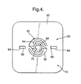
- F igs. 4 and 5 are further diagrammatic views of the jointed arrangement of
Fig. 3 ; - F ig. 6 is a diagrammatic plan view of a first ductile sheet of the jointed arrangement of
Figs. 3 to 5 ; - F ig. 7 is a diagrammatic side view of a second ductile sheet of the jointed arrangement of
Figs. 3 to 5 ; - F ig. 8 is an enlarged diagrammatic view of part of the jointed arrangement of
Figs. 3 to 5 ; - F ig. 9 is a diagrammatic view of part of a alternative second ductile sheet for an alternative jointed arrangement;
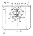
- F ig. 10 is a diagrammatic view of an alternative jointed arrangement including the alternative second ductile sheet of
Fig. 9 ; and - F ig. 11 is a diagrammatic plan view of an alternative first ductile sheet.
- Referring to the drawings, there is shown a
jointed arrangement 30 in which afirst ductile sheet 32 is secured to acomponent 34 in the form of asecond ductile sheet 36. Thefirst ductile sheet 32 is secured along anedge 38 of thesecond ductile sheet 36 in such a way that respective planes X-X and Y-Y of the first andsecond ductile sheets second ductile sheets - The
first ductile sheet 32 includes adeformable region 42 in substantially the centre of which is located anaperture 40. Thedeformable region 42 generally comprises a plurality ofdeformable ribs 44 extending between thefirst ductile sheet 32 and theaperture 40 which is defined by a generallyannular ring member 46. In the embodiment illustrated inFig. 6 , thedeformable ribs 44 are in the form ofspokes 48. Thedeformable ribs 44 and theannular member 46 defining theaperture 40 are formed by removing appropriate material from thefirst ductile sheet 32, for example by stamping or another suitable metalworking operation. - Referring in particular to
Figs. 3 and7 , it will be seen that thesecond ductile sheet 36 defines arecess 50. Therecess 50 extends into apassage 52 which, as can be seen clearly inFig. 8 , includes anut receiving portion 54 for receiving aconventional nut 55 having an internally threadedaperture 56. In order to initially retain thenut 55 within thenut receiving portion 54, thesecond ductile sheet 36 includes anut retaining member 58. - Referring initially to
Fig. 7 , it will be seen that thenut retaining member 58 comprises twolateral members upstanding member 62. Following location of thenut 55 within thenut receiving portion 54, as shown inFig. 8 thelateral members upstanding member 62 enters the internally threadedaperture 56 of thenut 55. Location of theupstanding member 62 in theaperture 56 provides sufficient constraint to thenut 55 so that it is unable to fall sideways out of thenut receiving portion 54. - When it is desired to secure the first and
second ductile sheets jointed arrangement 30 having a T-joint, the first andsecond ductile sheets deformable region 42 of thefirst ductile sheet 32 is located substantially adjacent to therecess 50 in thesecond ductile sheet 36. - In order to facilitate appropriate relative location of the
deformable region 42 and therecess 50 in the respective first andsecond ductile sheets second ductile sheets recesses 64 in thefirst ductile sheet 32 and locatingprojections 66 which extend from theedge 38 of thesecond ductile sheet 36 and which are locatable in the locatingrecesses 64 in thefirst ductile sheet 32. - After a
nut 55 has been located in thenut receiving portion 54 in thesecond ductile sheet 36 and thenut retaining member 58 appropriately deformed to retain thenut 55 in position in thenut receiving portion 54, and with the first andsecond ductile sheets fastener 68 having ahead 70 and a threadedshank 72 is used to secure the first andsecond ductile sheets - As can be seen clearly in
Figs. 3 and4 , the threadedshank 72 is passed through theaperture 40 defined by thedeformable region 42 in thefirst ductile sheet 32, through therecess 50 in thesecond ductile sheet 36 and into thepassage 52 until it encounters the threadednut 55. Upon encountering the threadednut 55, an appropriate tool (not shown) is used to rotate the threadedfastener 68 such that the threadedshank 72 enters into threaded engagement with the threaded formation of the internally threadedaperture 56 of thenut 55. As soon as the threadedshank 72 enters into engagement with the internally threadedaperture 56, thenut 55 is adequately retained in thenut receiving portion 54 by the threadedfastener 68 and thenut retaining member 58 is no longer needed. Accordingly, during continued rotation of the threadedfastener 68 to tighten it, atip 73 of the threadedshank 72 engages theupstanding member 62 of thenut retaining member 58 and pushes it out of the threadedaperture 56, thereby deforming thelateral members - Continued rotation of the threaded
fastener 68 results in a force between thenut 55 and theannular member 46 with which thehead 70 of the threadedfastener 68 is in engagement. Since theannular member 46 is supported by thedeformable ribs 44, thedeformable region 42, which comprises thedeformable ribs 44 and theannular member 46, deforms out of the plane of the firstductile sheet 32 such that thedeformable ribs 44 and theannular member 46 enter into therecess 50 in the secondductile sheet 36. This is highly advantageous as it enables thehead 70 of the threadedfastener 68 to become at least coplanar with the firstductile sheet 32, or indeed under continued rotation of the threadedfastener 68 to tighten it, to at least partially enter into therecess 50 in the secondductile sheet 36. In both of these cases, entry of thedeformable ribs 44 and theannular member 46 into therecess 50 in the secondductile sheet 36 ensures that the threadedfastener 68 can be tightened to a sufficient extent that thehead 70 of the threaded fastener does not protrude above anouter surface 74 of the firstductile sheet 32. - In order to prevent excessive deformation of the
deformable ribs 44 which could result in them being damaged, therecess 50 includesshoulders 82 against which thedeformable ribs 44 abut when the threadedfastener 68 has been tightened to a sufficient extent. - The
nut receiving portion 54 includes ananti-rotation region 90 which, in the embodiment ofFig. 8 , is defined by taperededges 76 of thepassage 52 in the secondductile sheet 36. As the threadedfastener 68 is rotated into threaded engagement with the threadednut 55 to tighten it and thereby secure the first and secondductile sheets nut 55, when thehead 70 of the threadedfastener 68 engages theannular member 46 of thedeformable region 46, causes thenut 55 to move in the direction of arrow A, into abutment withshoulders 78. In this position, the distance between thetapered edges 76 is less than the outer diameter of thenut 55, thus causing localised deformation of the secondductile sheet 36 and causing the taperededges 76 to firmly engage the nut and prevent it from rotating within theanti-rotation region 90 of thenut receiving portion 54. -
Figs. 9 and10 illustrate an alternative embodiment in which features corresponding to the embodiment ofFigs. 3 to 8 are given the same reference numerals, prefixed by the number 1. - In the embodiment of
Figs. 9 and10 , theedges 176 of thepassage 152 in the secondductile sheet 136 include inwardly directedprojections 192 defining theanti-rotation region 190. The distance between innermost points of the inwardly directedprojections 192 is less than the outer diameter of thenut 155. Accordingly, when thenut 155 engages theprojections 192, during rotation of the threadedfastener 168 to tighten it, the force exerted on theprojections 192 by thenut 155 causes localised deformation of the secondductile sheet 136, and in particular deformation of theprojections 192. Thenut 155 is thus firmly gripped in theanti-rotation region 190 of thenut receiving portion 154. - In order to permit deformation of the
projections 192 and hence localised deformation of the secondductile sheet 136 in the region of the inwardly directedprojections 192, the secondductile sheet 136 includesapertures 196 substantially adjacent to theprojections 192. When a comparison is made betweenFigs. 9 and10 , it will be readily seen that theapertures 196 have permitted localised deformation of the secondductile sheet 136 adjacent to thedeformed projections 192. - The provision of an
anti-rotation region nut nut ductile sheet ductile sheet fastener ductile sheets nut anti-rotation region nut 55 essentially having become jammed in theanti-rotation region nut receiving portion fastener nut nut receiving portion fastener -
Fig. 11 shows an alternative form of firstductile sheet 32 in which thedeformable ribs 44 are generally spiral or helical and are formed by providing a spiral or helical cut through the material of the firstductile sheet 32, centred on theaperture 40. - Although embodiments of the invention have been described in the preceding paragraphs with reference to various examples, it should be appreciated that various modifications to the examples given may be made without departing from the scope of the present invention, as claimed.
- For example, any suitable form of threaded
fastener 68 may be used to secure the first and secondductile sheets component 34 does not necessarily have to be in the form of a ductile sheet and could alternatively be any suitably shaped component. Thedeformable region 42 may be of any suitable configuration and formed by any suitable method.
Claims (17)
- A jointed arrangement (30, 130) comprising a first ductile sheet (32, 132) and a component (34, 134), wherein the first ductile sheet includes an aperture (40, 140) for receiving a threaded fastener (68, 168), the fastener engaging a threaded nut (55) to secure the ductile sheet (32, 132) to the component (34, 134), characterised in that the ductile sheet (32, 132) includes a deformable region (42, 142) in which the aperture (40, 140) is defined whereby the deformable region (42, 142) is deformable out of the plane (X-X) of the ductile sheet (32, 132) during tightening of the threaded fastener (68, 168) to secure the ductile sheet (32, 132) to the component (34, 134).
- A jointed arrangement (30, 130) according to claim 1, wherein the component (36, 136) includes a recess (50, 150) in which the deformable region (42, 142) of the first ductile sheet (32, 132) is received following tightening of the threaded fastener (68, 168) to secure the first ductile sheet (32, 132) to the second ductile sheet (36, 136).
- A jointed arrangement (30, 130) according to claim 1 or claim 2, wherein component (36, 136) includes a passage (52, 152), extending from the recess (50, 150) for receiving a threaded shank (72, 172) of the threaded fastener (68, 168).
- A jointed arrangement (30, 130) according to claim 3, wherein the passage (52, 152) includes a nut receiving portion (54, 154) for receiving the threaded nut (55, 155) in which the threaded shank (72, 172) of the threaded fastener (68, 168) is locatable to thereby secure the first ductile sheet (32, 132) to the component (36, 136).
- A jointed arrangement (30, 130) according to claim 4, wherein the nut receiving portion (54, 154) includes an anti-rotation region (90, 190) which is operable to prevent rotation of the threaded nut (55, 155) during rotation of the threaded shank (72, 172) of the threaded fastener (68, 168) relative to the threaded nut (55, 155).
- A jointed arrangement (30) according to claim 5, wherein edges (76) of the passage (52) are tapered to define the anti-rotation region (90).
- A jointed arrangement (130) according to claim 5, wherein edges (176) of the passage (152) include inwardly directed projections (192) to define the anti-rotation region (190).
- A jointed arrangement (130) according to claim 7, wherein the component (136) includes apertures (196) substantially adjacent to the inwardly directed projections (192) to permit localised deformation of the second ductile sheet (136).
- A jointed arrangement (30, 130) according to any of claims 4 to 8, wherein the component (36, 136) includes a nut retaining member (58, 158) which is locatable in an aperture (56, 156) of the threaded nut (55, 155) to retain the nut (55, 155) in the nut receiving portion (54, 154) prior to insertion of the threaded shank (72, 172) of the threaded fastener (68, 168) into the aperture (56, 156) of the threaded nut (55, 155).
- A jointed arrangement (30, 130) according to claim 9, wherein the nut retaining member (58, 158) is displaceable out of the aperture (56, 156) of the threaded nut (55, 155) by the threaded shank (72, 172) of the threaded fastener (68, 168) during tightening rotation of the threaded fastener (68, 168).
- A jointed arrangement (30, 130) according to any preceding claim, wherein the first ductile sheet (32, 132) includes at least one locating recess (64, 164) and the component (36, 136) includes at least one complementary locating projection (66, 166).
- A jointed arrangement according to any of the preceding claims wherein the component (34, 134) is in the form of a second ductile sheet (36, 136) to which the first ductile sheet (32, 132) is secured, wherein the first ductile sheet (32, 132) is secured along an edge (38, 138) of the second ductile sheet (36, 136) such that the planes (X-X, Y-Y) of the first and second ductile sheets (32, 132, 36, 136) are generally perpendicular.
- A joined arrangement according to any preceding claim, wherein the aperture (40, 140) in the first ductile sheet (32, 132) is defined substantially centrally in the deformable region (42, 142).
- A joined arrangement according to any preceding claim, wherein the aperture (40', 140) is defined by an annular member (46, 146).
- A joined arrangement according to claim 14, wherein the deformable region (40, 140) comprises a plurality of deformable ribs (44, 144) extending between the ductile sheet (32, 132) and the annular member (46, 146) to support the annular member (46, 146) and enable its deformation out of the plane (X-X) of the ductile sheet (32, 132) during tightening of the threaded fastener (68, 168).
- A joined arrangement according to claim 15, wherein the deformable ribs (44, 144) are in the form of spokes (48, 148).
- A joined arrangement according to claim 15 or claim 16, wherein the deformable ribs (44, 144) are of generally helical or spiral configuration.
Applications Claiming Priority (2)
| Application Number | Priority Date | Filing Date | Title |
|---|---|---|---|
| GBGB0705938.9A GB0705938D0 (en) | 2007-03-28 | 2007-03-28 | Component joining |
| PCT/GB2008/000729 WO2008117011A1 (en) | 2007-03-28 | 2008-03-03 | Component joining |
Publications (2)
| Publication Number | Publication Date |
|---|---|
| EP2132448A1 EP2132448A1 (en) | 2009-12-16 |
| EP2132448B1 true EP2132448B1 (en) | 2014-06-18 |
Family
ID=38050328
Family Applications (1)
| Application Number | Title | Priority Date | Filing Date |
|---|---|---|---|
| EP08718596.3A Not-in-force EP2132448B1 (en) | 2007-03-28 | 2008-03-03 | Component joining |
Country Status (4)
| Country | Link |
|---|---|
| US (1) | US20100034583A1 (en) |
| EP (1) | EP2132448B1 (en) |
| GB (1) | GB0705938D0 (en) |
| WO (1) | WO2008117011A1 (en) |
Cited By (1)
| Publication number | Priority date | Publication date | Assignee | Title |
|---|---|---|---|---|
| EP3035465A1 (en) | 2014-12-17 | 2016-06-22 | Hager Electro GmbH & Co. KG | Fastening device for fastening an installation cabinet in a wall shell opening |
Family Cites Families (13)
| Publication number | Priority date | Publication date | Assignee | Title |
|---|---|---|---|---|
| US2993573A (en) * | 1959-09-01 | 1961-07-25 | Clarence F Bloedow | Connector |
| US3498655A (en) * | 1968-09-18 | 1970-03-03 | Hewlett Packard Co | Panel mount and fastener |
| US3967432A (en) * | 1975-07-23 | 1976-07-06 | Southco, Inc. | Panel edge fastener receptacle and joint |
| US4116510A (en) * | 1977-03-03 | 1978-09-26 | Gte Automatic Electric Laboratories Incorporated | Chassis formed of sheet stock |
| JPS6173828U (en) * | 1984-10-18 | 1986-05-19 | ||
| US4657423A (en) * | 1985-12-30 | 1987-04-14 | Gte Communications Systems Corp. | Fastener and receptacle arrangement for perpendicularly connecting pieces of flat stock material |
| JP2842061B2 (en) * | 1992-07-15 | 1998-12-24 | 株式会社ダイフク | Frame shelf with fastening part |
| JPH0988919A (en) * | 1995-09-20 | 1997-03-31 | Sekisui Chem Co Ltd | Synthetic resin molded product and its mounting structure |
| US6488458B2 (en) * | 1996-02-23 | 2002-12-03 | Hitachi, Ltd. | Taper implant and a screw-fastening structure using a taper implant with female threads |
| US6267446B1 (en) * | 1997-05-14 | 2001-07-31 | Home Reserve, Inc. | Compressed upholstered furniture assembly kit and method of manufacture |
| DE19951742C1 (en) * | 1999-10-27 | 2001-07-12 | Raymond A & Cie | Fastening element for releasably connecting sheet metal plates arranged at right angles to one another |
| FR2895467B1 (en) * | 2005-12-23 | 2009-04-17 | Sidel Sas | ARRANGEMENT FOR ASSEMBLING TWO PARTS THROUGH VISE THROUGH A SCREW-NUT ASSEMBLY |
| US8434960B2 (en) * | 2008-11-26 | 2013-05-07 | Applied Minds, Llc | Captive bolt mechanism and process for structural assembly of planar components |
-
2007
- 2007-03-28 GB GBGB0705938.9A patent/GB0705938D0/en not_active Ceased
-
2008
- 2008-03-03 WO PCT/GB2008/000729 patent/WO2008117011A1/en not_active Ceased
- 2008-03-03 US US12/449,772 patent/US20100034583A1/en not_active Abandoned
- 2008-03-03 EP EP08718596.3A patent/EP2132448B1/en not_active Not-in-force
Cited By (2)
| Publication number | Priority date | Publication date | Assignee | Title |
|---|---|---|---|---|
| EP3035465A1 (en) | 2014-12-17 | 2016-06-22 | Hager Electro GmbH & Co. KG | Fastening device for fastening an installation cabinet in a wall shell opening |
| DE102014226307A1 (en) | 2014-12-17 | 2016-06-23 | Hager Electro Gmbh & Co. Kg | Fastening device for fastening an installation box in a wall shell opening |
Also Published As
| Publication number | Publication date |
|---|---|
| US20100034583A1 (en) | 2010-02-11 |
| GB0705938D0 (en) | 2007-05-09 |
| WO2008117011A1 (en) | 2008-10-02 |
| EP2132448A1 (en) | 2009-12-16 |
Similar Documents
| Publication | Publication Date | Title |
|---|---|---|
| US12085110B2 (en) | Nut and tightening method | |
| TWI451025B (en) | Nut with lug flare | |
| EP1160466B1 (en) | U-nut fastener | |
| US6758645B2 (en) | Locking cage fastener | |
| EP1598143B1 (en) | Mounting structure with energy absorber | |
| US20150345536A1 (en) | Cage nut | |
| EP0556438A1 (en) | Fastening member, fastening machine element set, and method of connecting fastening machine elements | |
| JP2024526398A (en) | Nut connection mechanism | |
| EP1097309B1 (en) | A joint for sheet material and a method of joining sheet material | |
| US3687501A (en) | Non-rotatable fastener | |
| EP2538000B1 (en) | Method for correcting ovality in wind turbine towers | |
| US4014245A (en) | Fastener | |
| EP2132448B1 (en) | Component joining | |
| EP2478230B1 (en) | System and method for fixedly connecting sheets | |
| US20100166522A1 (en) | Mounting/assembly element for assembling workpieces, particularly overlapping plates and/or components | |
| EP3812600B1 (en) | Single side access sheet metal nut | |
| JP3433726B2 (en) | Detent mechanism for rotary fastener, first and second washers used for the mechanism, and method of releasing the mechanism | |
| EP0728950A1 (en) | Method of securing members together and fastener therefor | |
| EP1880800B1 (en) | Threaded fastener and method of installation | |
| JP2860522B2 (en) | Metal fixing bracket for steel base material | |
| US20020050029A1 (en) | Mounting structure for energy absorber | |
| EP3500762B1 (en) | A locking plate unit and a vehicle comprising such a locking plate unit | |
| KR102916220B1 (en) | Self-clinching and self-piercing construction elements with multi-purpose pilots | |
| JP6016652B2 (en) | Two-stage joining method of members, and nut for one-stage joining of members used in the method | |
| US8328489B2 (en) | Self-pierce rivets and an adjustable strap handle |
Legal Events
| Date | Code | Title | Description |
|---|---|---|---|
| PUAI | Public reference made under article 153(3) epc to a published international application that has entered the european phase |
Free format text: ORIGINAL CODE: 0009012 |
|
| 17P | Request for examination filed |
Effective date: 20091028 |
|
| AK | Designated contracting states |
Kind code of ref document: A1 Designated state(s): AT BE BG CH CY CZ DE DK EE ES FI FR GB GR HR HU IE IS IT LI LT LU LV MC MT NL NO PL PT RO SE SI SK TR |
|
| DAX | Request for extension of the european patent (deleted) | ||
| GRAP | Despatch of communication of intention to grant a patent |
Free format text: ORIGINAL CODE: EPIDOSNIGR1 |
|
| INTG | Intention to grant announced |
Effective date: 20140320 |
|
| GRAS | Grant fee paid |
Free format text: ORIGINAL CODE: EPIDOSNIGR3 |
|
| GRAA | (expected) grant |
Free format text: ORIGINAL CODE: 0009210 |
|
| AK | Designated contracting states |
Kind code of ref document: B1 Designated state(s): AT BE BG CH CY CZ DE DK EE ES FI FR GB GR HR HU IE IS IT LI LT LU LV MC MT NL NO PL PT RO SE SI SK TR |
|
| REG | Reference to a national code |
Ref country code: GB Ref legal event code: FG4D |
|
| REG | Reference to a national code |
Ref country code: CH Ref legal event code: EP |
|
| REG | Reference to a national code |
Ref country code: AT Ref legal event code: REF Ref document number: 673520 Country of ref document: AT Kind code of ref document: T Effective date: 20140715 |
|
| REG | Reference to a national code |
Ref country code: IE Ref legal event code: FG4D |
|
| REG | Reference to a national code |
Ref country code: DE Ref legal event code: R096 Ref document number: 602008032826 Country of ref document: DE Effective date: 20140731 |
|
| PG25 | Lapsed in a contracting state [announced via postgrant information from national office to epo] |
Ref country code: LT Free format text: LAPSE BECAUSE OF FAILURE TO SUBMIT A TRANSLATION OF THE DESCRIPTION OR TO PAY THE FEE WITHIN THE PRESCRIBED TIME-LIMIT Effective date: 20140618 Ref country code: FI Free format text: LAPSE BECAUSE OF FAILURE TO SUBMIT A TRANSLATION OF THE DESCRIPTION OR TO PAY THE FEE WITHIN THE PRESCRIBED TIME-LIMIT Effective date: 20140618 Ref country code: NO Free format text: LAPSE BECAUSE OF FAILURE TO SUBMIT A TRANSLATION OF THE DESCRIPTION OR TO PAY THE FEE WITHIN THE PRESCRIBED TIME-LIMIT Effective date: 20140918 Ref country code: CY Free format text: LAPSE BECAUSE OF FAILURE TO SUBMIT A TRANSLATION OF THE DESCRIPTION OR TO PAY THE FEE WITHIN THE PRESCRIBED TIME-LIMIT Effective date: 20140618 Ref country code: GR Free format text: LAPSE BECAUSE OF FAILURE TO SUBMIT A TRANSLATION OF THE DESCRIPTION OR TO PAY THE FEE WITHIN THE PRESCRIBED TIME-LIMIT Effective date: 20140919 |
|
| REG | Reference to a national code |
Ref country code: NL Ref legal event code: VDEP Effective date: 20140618 |
|
| REG | Reference to a national code |
Ref country code: AT Ref legal event code: MK05 Ref document number: 673520 Country of ref document: AT Kind code of ref document: T Effective date: 20140618 |
|
| REG | Reference to a national code |
Ref country code: LT Ref legal event code: MG4D |
|
| PG25 | Lapsed in a contracting state [announced via postgrant information from national office to epo] |
Ref country code: LV Free format text: LAPSE BECAUSE OF FAILURE TO SUBMIT A TRANSLATION OF THE DESCRIPTION OR TO PAY THE FEE WITHIN THE PRESCRIBED TIME-LIMIT Effective date: 20140618 Ref country code: SE Free format text: LAPSE BECAUSE OF FAILURE TO SUBMIT A TRANSLATION OF THE DESCRIPTION OR TO PAY THE FEE WITHIN THE PRESCRIBED TIME-LIMIT Effective date: 20140618 Ref country code: HR Free format text: LAPSE BECAUSE OF FAILURE TO SUBMIT A TRANSLATION OF THE DESCRIPTION OR TO PAY THE FEE WITHIN THE PRESCRIBED TIME-LIMIT Effective date: 20140618 |
|
| PG25 | Lapsed in a contracting state [announced via postgrant information from national office to epo] |
Ref country code: CZ Free format text: LAPSE BECAUSE OF FAILURE TO SUBMIT A TRANSLATION OF THE DESCRIPTION OR TO PAY THE FEE WITHIN THE PRESCRIBED TIME-LIMIT Effective date: 20140618 Ref country code: EE Free format text: LAPSE BECAUSE OF FAILURE TO SUBMIT A TRANSLATION OF THE DESCRIPTION OR TO PAY THE FEE WITHIN THE PRESCRIBED TIME-LIMIT Effective date: 20140618 Ref country code: PT Free format text: LAPSE BECAUSE OF FAILURE TO SUBMIT A TRANSLATION OF THE DESCRIPTION OR TO PAY THE FEE WITHIN THE PRESCRIBED TIME-LIMIT Effective date: 20141020 Ref country code: ES Free format text: LAPSE BECAUSE OF FAILURE TO SUBMIT A TRANSLATION OF THE DESCRIPTION OR TO PAY THE FEE WITHIN THE PRESCRIBED TIME-LIMIT Effective date: 20140618 Ref country code: SK Free format text: LAPSE BECAUSE OF FAILURE TO SUBMIT A TRANSLATION OF THE DESCRIPTION OR TO PAY THE FEE WITHIN THE PRESCRIBED TIME-LIMIT Effective date: 20140618 Ref country code: RO Free format text: LAPSE BECAUSE OF FAILURE TO SUBMIT A TRANSLATION OF THE DESCRIPTION OR TO PAY THE FEE WITHIN THE PRESCRIBED TIME-LIMIT Effective date: 20140618 |
|
| PG25 | Lapsed in a contracting state [announced via postgrant information from national office to epo] |
Ref country code: IS Free format text: LAPSE BECAUSE OF FAILURE TO SUBMIT A TRANSLATION OF THE DESCRIPTION OR TO PAY THE FEE WITHIN THE PRESCRIBED TIME-LIMIT Effective date: 20141018 Ref country code: AT Free format text: LAPSE BECAUSE OF FAILURE TO SUBMIT A TRANSLATION OF THE DESCRIPTION OR TO PAY THE FEE WITHIN THE PRESCRIBED TIME-LIMIT Effective date: 20140618 Ref country code: NL Free format text: LAPSE BECAUSE OF FAILURE TO SUBMIT A TRANSLATION OF THE DESCRIPTION OR TO PAY THE FEE WITHIN THE PRESCRIBED TIME-LIMIT Effective date: 20140618 Ref country code: PL Free format text: LAPSE BECAUSE OF FAILURE TO SUBMIT A TRANSLATION OF THE DESCRIPTION OR TO PAY THE FEE WITHIN THE PRESCRIBED TIME-LIMIT Effective date: 20140618 |
|
| REG | Reference to a national code |
Ref country code: DE Ref legal event code: R097 Ref document number: 602008032826 Country of ref document: DE |
|
| PLBE | No opposition filed within time limit |
Free format text: ORIGINAL CODE: 0009261 |
|
| STAA | Information on the status of an ep patent application or granted ep patent |
Free format text: STATUS: NO OPPOSITION FILED WITHIN TIME LIMIT |
|
| PG25 | Lapsed in a contracting state [announced via postgrant information from national office to epo] |
Ref country code: DK Free format text: LAPSE BECAUSE OF FAILURE TO SUBMIT A TRANSLATION OF THE DESCRIPTION OR TO PAY THE FEE WITHIN THE PRESCRIBED TIME-LIMIT Effective date: 20140618 Ref country code: IT Free format text: LAPSE BECAUSE OF FAILURE TO SUBMIT A TRANSLATION OF THE DESCRIPTION OR TO PAY THE FEE WITHIN THE PRESCRIBED TIME-LIMIT Effective date: 20140618 |
|
| 26N | No opposition filed |
Effective date: 20150319 |
|
| PG25 | Lapsed in a contracting state [announced via postgrant information from national office to epo] |
Ref country code: BE Free format text: LAPSE BECAUSE OF FAILURE TO SUBMIT A TRANSLATION OF THE DESCRIPTION OR TO PAY THE FEE WITHIN THE PRESCRIBED TIME-LIMIT Effective date: 20140618 |
|
| PG25 | Lapsed in a contracting state [announced via postgrant information from national office to epo] |
Ref country code: SI Free format text: LAPSE BECAUSE OF FAILURE TO SUBMIT A TRANSLATION OF THE DESCRIPTION OR TO PAY THE FEE WITHIN THE PRESCRIBED TIME-LIMIT Effective date: 20140618 |
|
| PG25 | Lapsed in a contracting state [announced via postgrant information from national office to epo] |
Ref country code: LU Free format text: LAPSE BECAUSE OF FAILURE TO SUBMIT A TRANSLATION OF THE DESCRIPTION OR TO PAY THE FEE WITHIN THE PRESCRIBED TIME-LIMIT Effective date: 20150303 Ref country code: MC Free format text: LAPSE BECAUSE OF FAILURE TO SUBMIT A TRANSLATION OF THE DESCRIPTION OR TO PAY THE FEE WITHIN THE PRESCRIBED TIME-LIMIT Effective date: 20140618 |
|
| REG | Reference to a national code |
Ref country code: CH Ref legal event code: PL |
|
| REG | Reference to a national code |
Ref country code: IE Ref legal event code: MM4A |
|
| PG25 | Lapsed in a contracting state [announced via postgrant information from national office to epo] |
Ref country code: CH Free format text: LAPSE BECAUSE OF NON-PAYMENT OF DUE FEES Effective date: 20150331 Ref country code: LI Free format text: LAPSE BECAUSE OF NON-PAYMENT OF DUE FEES Effective date: 20150331 Ref country code: IE Free format text: LAPSE BECAUSE OF NON-PAYMENT OF DUE FEES Effective date: 20150303 |
|
| REG | Reference to a national code |
Ref country code: FR Ref legal event code: PLFP Year of fee payment: 9 |
|
| PG25 | Lapsed in a contracting state [announced via postgrant information from national office to epo] |
Ref country code: MT Free format text: LAPSE BECAUSE OF FAILURE TO SUBMIT A TRANSLATION OF THE DESCRIPTION OR TO PAY THE FEE WITHIN THE PRESCRIBED TIME-LIMIT Effective date: 20140618 |
|
| REG | Reference to a national code |
Ref country code: FR Ref legal event code: PLFP Year of fee payment: 10 |
|
| PG25 | Lapsed in a contracting state [announced via postgrant information from national office to epo] |
Ref country code: HU Free format text: LAPSE BECAUSE OF FAILURE TO SUBMIT A TRANSLATION OF THE DESCRIPTION OR TO PAY THE FEE WITHIN THE PRESCRIBED TIME-LIMIT; INVALID AB INITIO Effective date: 20080303 Ref country code: BG Free format text: LAPSE BECAUSE OF FAILURE TO SUBMIT A TRANSLATION OF THE DESCRIPTION OR TO PAY THE FEE WITHIN THE PRESCRIBED TIME-LIMIT Effective date: 20140618 |
|
| PG25 | Lapsed in a contracting state [announced via postgrant information from national office to epo] |
Ref country code: TR Free format text: LAPSE BECAUSE OF FAILURE TO SUBMIT A TRANSLATION OF THE DESCRIPTION OR TO PAY THE FEE WITHIN THE PRESCRIBED TIME-LIMIT Effective date: 20140618 |
|
| REG | Reference to a national code |
Ref country code: FR Ref legal event code: PLFP Year of fee payment: 11 |
|
| PGFP | Annual fee paid to national office [announced via postgrant information from national office to epo] |
Ref country code: GB Payment date: 20220322 Year of fee payment: 15 Ref country code: DE Payment date: 20220329 Year of fee payment: 15 |
|
| PGFP | Annual fee paid to national office [announced via postgrant information from national office to epo] |
Ref country code: FR Payment date: 20220325 Year of fee payment: 15 |
|
| P01 | Opt-out of the competence of the unified patent court (upc) registered |
Effective date: 20230528 |
|
| REG | Reference to a national code |
Ref country code: DE Ref legal event code: R119 Ref document number: 602008032826 Country of ref document: DE |
|
| GBPC | Gb: european patent ceased through non-payment of renewal fee |
Effective date: 20230303 |
|
| PG25 | Lapsed in a contracting state [announced via postgrant information from national office to epo] |
Ref country code: GB Free format text: LAPSE BECAUSE OF NON-PAYMENT OF DUE FEES Effective date: 20230303 |
|
| PG25 | Lapsed in a contracting state [announced via postgrant information from national office to epo] |
Ref country code: GB Free format text: LAPSE BECAUSE OF NON-PAYMENT OF DUE FEES Effective date: 20230303 Ref country code: FR Free format text: LAPSE BECAUSE OF NON-PAYMENT OF DUE FEES Effective date: 20230331 Ref country code: DE Free format text: LAPSE BECAUSE OF NON-PAYMENT OF DUE FEES Effective date: 20231003 |