EP2131532A1 - Communication terminal, distribution device, error notification method, and error notification program - Google Patents
Communication terminal, distribution device, error notification method, and error notification program Download PDFInfo
- Publication number
- EP2131532A1 EP2131532A1 EP20080738909 EP08738909A EP2131532A1 EP 2131532 A1 EP2131532 A1 EP 2131532A1 EP 20080738909 EP20080738909 EP 20080738909 EP 08738909 A EP08738909 A EP 08738909A EP 2131532 A1 EP2131532 A1 EP 2131532A1
- Authority
- EP
- European Patent Office
- Prior art keywords
- transmission data
- unit
- distribution
- data
- error
- Prior art date
- Legal status (The legal status is an assumption and is not a legal conclusion. Google has not performed a legal analysis and makes no representation as to the accuracy of the status listed.)
- Withdrawn
Links
Images



Classifications
-
- H—ELECTRICITY
- H04—ELECTRIC COMMUNICATION TECHNIQUE
- H04L—TRANSMISSION OF DIGITAL INFORMATION, e.g. TELEGRAPHIC COMMUNICATION
- H04L1/00—Arrangements for detecting or preventing errors in the information received
- H04L1/12—Arrangements for detecting or preventing errors in the information received by using return channel
- H04L1/16—Arrangements for detecting or preventing errors in the information received by using return channel in which the return channel carries supervisory signals, e.g. repetition request signals
- H04L1/18—Automatic repetition systems, e.g. Van Duuren systems
- H04L1/1867—Arrangements specially adapted for the transmitter end
-
- H—ELECTRICITY
- H04—ELECTRIC COMMUNICATION TECHNIQUE
- H04L—TRANSMISSION OF DIGITAL INFORMATION, e.g. TELEGRAPHIC COMMUNICATION
- H04L47/00—Traffic control in data switching networks
- H04L47/10—Flow control; Congestion control
-
- H—ELECTRICITY
- H04—ELECTRIC COMMUNICATION TECHNIQUE
- H04L—TRANSMISSION OF DIGITAL INFORMATION, e.g. TELEGRAPHIC COMMUNICATION
- H04L1/00—Arrangements for detecting or preventing errors in the information received
- H04L2001/0092—Error control systems characterised by the topology of the transmission link
- H04L2001/0097—Relays
-
- H—ELECTRICITY
- H04—ELECTRIC COMMUNICATION TECHNIQUE
- H04L—TRANSMISSION OF DIGITAL INFORMATION, e.g. TELEGRAPHIC COMMUNICATION
- H04L2212/00—Encapsulation of packets
Definitions
- the present invention relates to a communication terminal apparatus that receives using a unidirectional communication network and that transmits using a bidirectional communication network, a distribution apparatus that distributes distribution data using a unidirectional communication network and that receives transmission data from each terminal being a distribution destination of the distribution data using a bidirectional communication network, and an error notification method and an error notification program of the above apparatuses.
- connection to a communication counterpart terminal apparatus is established through a LAN (Local Area Network) or a WAN (Wide Area Network) that is configured according to any one of various standards such as Ethernet (a registered trade mark), an FDDI (Fiber-Distributed Data Interface), and an ATM (Asynchronous Transfer Mode).
- LAN Local Area Network
- WAN Wide Area Network
- Ethernet a registered trade mark
- FDDI Fiber-Distributed Data Interface
- ATM Asynchronous Transfer Mode
- a given relay apparatus such as a router is equipped between networks.
- the relay apparatus has a function of monitoring whether transmission data transmitted to a network is transmittable. Therefore, when the relay apparatus finds an error in the transmission data, the relay apparatus transmits an error message corresponding to the content of the error to a communication terminal apparatus that is the transmission source of the transmission data.
- An error message may be, for example, a packet too big message, a destination unreachable message, a time exceeded message, and a parameter problem message.
- IPv6 Internet Protocol Version 6
- MTU Maximum Transmission Unit
- Fig. 10 is a diagram for explaining a monitoring process of transmission data by a relay apparatus.
- the relay apparatus not only relays between networks but also monitors the capacity of transmission data such that a terminal apparatus for transmission may transmit transmission data of a capacity corresponding to the MTU of a network.
- two networks are configured between two communication terminal apparatuses 1000 and 1010.
- Relay apparatuses R1 and R2, and R3 and R4 are respectively disposed in the networks A and B.
- the communication terminal apparatus 1010 is a terminal for transmission
- the communication terminal apparatus 1000 is a terminal for reception
- the MTU of the networks A and B is 1,500 [bytes].
- transmission data of a capacity of 1,500 [bytes] or less, representing packet size is output to the communication processing interface (I/F) 1012A and transmission data of a packet size of 1,500 [bytes] or larger is output to the communication processing interface (I/F) 1012B.
- the transmission data transmitted from the communication processing interface (I/F) 1012A to the network A has a capacity equal to or less than the MTU and therefore, the transmission data is received by the communication processing interface (I/F) 1001A of the communication terminal apparatus 1000 for reception through the relay apparatuses R2 and R1 (S11).
- the transmission data transmitted from the communication processing interface (I/F) 1012B to the network B has a capacity exceeding the MTU and the relay apparatus R3 detects that the capacity is larger than the MTU (S12).
- the transmission data is not transmitted to the communication processing interface (I/F) 1001B of the communication terminal apparatus 1000 and instead, an error message "Packet Too Big” indicating that the transmission data exceeds the MTU is transmitted to the communication terminal apparatus 1010 (S13).
- the interface (I/F) 1012B of the communication terminal apparatus 1010 When the communication processing interface (I/F) 1012B of the communication terminal apparatus 1010 receives the error message "Packet Too Big” from the network B, the interface (I/F) 1012B reduces the packet size of the transmission data.
- This series of processing is known as “Path MTU Discovery (RFC 1981)” (see, for example, NonPatent Literature 1).
- Fig. 11 is a diagram for explaining a monitoring process of a relay apparatus in a network using the UDLR.
- the network using the UDLR includes a distribution apparatus 1100 that distributes data (distribution data) using a unidirectional communication network, and a communication terminal apparatus 1110 that receives the transmission data.
- the distribution apparatus 1100 and the communication terminal apparatus 1110 are connected to a unidirectional communication network C dedicated for distribution, and a bidirectional communication network D (a normal network) used for transmitting data from the communication terminal apparatus 1110 to the distribution apparatus 1100.
- the distribution data When the distribution data is distributed from the distribution apparatus 1100 to the communication terminal apparatus 1110, the distribution data is output from a distributing interface (I/F) 1101 to the unidirectional communication network C (S00). From the distribution apparatus 1100, the distribution data may be distributed to a specific communication terminal apparatus or may be distributed to multiple communication terminal apparatuses as a broadcast wave.
- a distributing interface I/F
- the distribution data may be distributed to a specific communication terminal apparatus or may be distributed to multiple communication terminal apparatuses as a broadcast wave.
- the communication terminal apparatus 1110 receives the distribution data using a receiving interface (I/F) 1112.
- a receiving interface (I/F) 1112 In a network using the UDLR, to transmit a response to the distribution apparatus 1100, transmission data is output from an OS/application unit 1111 to the receiving interface (I/F) 1112 that is connected to the unidirectional communication network C (S20).
- the receiving interface (I/F) 1112 realizes a virtual bidirectional communication network by transmitting the transmission data to the bidirectional communication network D. Therefore, the receiving interface (I/F) 1112 applies a given process to the transmission data and outputs the processed transmission data to a communication processing interface (I/F) 1113 (S21).
- the communication processing interface (I/F) 1113 transmits the transmission data to the bidirectional communication network D.
- the transmission data has a capacity equal to or less than the MTU
- the transmission data is transmitted to the distribution apparatus 1100 through the relay apparatuses R3 and R4.
- Nonpatent Literature 1 Izumi, Miki, "Serial Article: invitation to IPv6 Networks (No. 3) 'Header Format of IPv6'", [online], October 5, 2001, Research Institute for Internet Strategies, Inc. , [Retrieved on July 7, 2006], on the Internet ⁇ URL:
- the above monitoring process using the relay apparatuses does not function normally when bidirectional communication is executed using a network for unidirectional communication.
- the relay apparatus R3 detects that the transmission data exceeds the MTU similarly to the example depicted in Fig. 10 .
- An error message "Packet Too Big” is transmitted from the relay apparatus R3 to the communication terminal apparatus 1110 (S23). Therefore, the transmission data is not transmitted to a receiving interface (I/F) 1102 of the distribution apparatus 1100.
- the error message "Packet Too Big” is transmitted to the communication processing interface (I/F) 1113 of the communication terminal apparatus 1110. In this manner, the communication processing interface (I/F) 1113 receives the message "Packet Too Big". However, in the UDLR network, the interface that actually outputs the transmission data from the apparatus is the receiving interface (I/F) 1112. Therefore, the message "Packet Too Big” does not reach the receiving interface (I/F) 1112.
- the OS/application unit 1111 recognizes the MTU of the bidirectional communication network D and reduces the packet size of the transmission data that is directly transmitted to the bidirectional communication network D.
- the OS/application unit 1111 recognizes this transmission data as transmission data to be transmitted from the receiving interface (I/F) 1112 to the unidirectional communication network C and accordingly executes processing.
- the OS/application unit 1111 does not reflect at all the message "Packet Too Big” that arrives at the communication processing interface (I/F) 1113 and the OS/application unit 1111 inevitably outputs, consecutively, transmission data having a packet size exceeding the MTU to the receiving interface (I/F) 1112. In this manner, in a UDLR network, "Path MTU Discovery" do not function.
- a UDLR network As described, in a UDLR network, error messages by a relay apparatus are not reflected at the communication terminal apparatus 1110. Therefore, in a conventional UDLR network, to prevent the capacity of any transmission data from exceeding the MTU, transmission is executed using the smallest value set as the MTU, as the capacity of the transmission data. Hence, only transmission data having the smallest capacity may be handled regardless of the actual MTU of a network and therefore, a problem has arisen in that the efficiency of the communication is poor.
- an object of the present invention is to provide a communication terminal apparatus, a distribution apparatus, an error notification method, and an error notification program that provide notification of an error to an interface that is the transmission source transmitting transmission data from which the error is detected, enabling the error to be resolved, even using a network that is configured to receive data from a communication counterpart using a unidirectional communication network.
- a communication terminal apparatus receives using a unidirectional communication network and transmits using a bidirectional communication network.
- the communication terminal apparatus includes a receiving unit that receives distribution data distributed through the unidirectional communication network; an accepting unit that accepts transmission data to be transmitted to a distribution source of the distribution data received by the receiving unit; and a communication processing unit that transmits the transmission data accepted by the accepting unit to the bidirectional communication network.
- the communication processing unit includes a detecting unit that detects an error message concerning the transmission data from the bidirectional communication network; a setting unit that sets the transmission data that includes the error message detected by the detecting unit, to be new transmission data; an error processing unit that subjects the new transmission data set by the setting unit to a process of resolving an error corresponding to the error message; and a transmitting unit that transmits the transmission data whose error has been resolved by the error processing unit to the bidirectional communication network to use the transmission data as the distribution data from the distribution source.
- the error notification does not end with a transmission of an error message to a unit unrelated to the transmission data setting as is conventionally executed, rather the transmission data is processed as new transmission data that includes the error message.
- the new transmission data is transmitted to the distribution apparatus to be distributed from the distribution apparatus to the transmission source as distribution data.
- a distribution apparatus includes a distributing unit that distributes distribution data using a unidirectional communication network; and a receiving unit that receives transmission data from a terminal that is a distribution destination of the distribution data, using a bidirectional communication network.
- the distributing unit distributes the transmission data as the distribution data to a terminal that is a transmission source of transmission data that includes an error message received by the receiving unit, when the receiving unit receives transmission data that includes an error message from a terminal.
- the transmission data received is distributed as distribution data to a terminal that is the transmission source of the transmission data. Therefore, the error message is directly distributed to the terminal that is the transmission source of the transmission data corresponding to the error message and thereby, enabling notification of the error.
- An error notification method is that of a communication terminal apparatus that receives by a unidirectional communication network and transmits by a bidirectional communication network.
- the error notification method includes a receiving step of receiving, distribution data distributed through the unidirectional communication network; an accepting step of accepting transmission data to be transmitted to a distribution source of the distribution data received at the receiving step; and a first transmitting step of transmitting the transmission data accepted at the accepting step to the bidirectional communication network; a setting step of setting, when an error message is detected with respect to the transmission data from the bidirectional communication network, the transmission data including the detected error message to be new transmission data; an error processing step of subjecting the new transmission data set at the setting step to a process of resolving an error corresponding to the error message; and a second transmitting step of transmitting the transmission data whose error has been resolved at the error processing step, to the bidirectional communication network to use the transmission data as the distribution data from the distribution source.
- the error notification does not end with a transmission of an error message to a unit unrelated to the transmission data setting as is conventionally executed, rather the transmission data is processed as new transmission data that includes the error message.
- the new transmission data is transmitted to the distribution apparatus to be distributed from the distribution apparatus to the transmission source as distribution data.
- An error notification method includes a receiving step of receiving via a bidirectional communication network and by a transmitting unit of a distribution apparatus, transmission data from a terminal that is a distribution destination of the distribution data; and a distributing step of distributing via a unidirectional communication network, by a distribution unit of the distribution apparatus and as distribution data, the transmission data to the terminal that is a transmission source of the transmission data received at the receiving step and inclusive of an error message.
- the transmission data received is distributed as distribution data to a terminal that is the transmission source of the transmission data. Therefore, the error message is directly distributed to the terminal that is the transmission source of the transmission data corresponding to the error message and thereby, enabling notification of the error.
- An error notification program causes a computer to execute the error notification method recited in claim 7 or 8.
- an effect is achieved in that error notification may be provided to an interface that is the transmission source transmitting transmission data from which the error is detected and thereby, the error may be resolved even using a network that is configured to receive data from a communication counterpart using a unidirectional communication network.
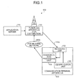
- a network configuration 100 includes an application server 110, a tunneling apparatus 120 that functions as a distribution apparatus, and a communication terminal apparatus 130.
- the network configuration 100 uses the UDLR and therefore, a unidirectional communication network 140a that is used when distribution data is distributed from the tunneling apparatus 120 to the communication terminal apparatus 130, and an IPv6 relaying network 140b that is bidirectional communicable and used when transmission data is transmitted from the communication terminal apparatus 130 to the tunneling apparatus 120 are connected between the tunneling apparatus 120 and the communication terminal apparatus 130.
- the application server 110 delivers to the tunneling apparatus 120, application data that is to be distributed to the communication terminal apparatus 130. More specifically, the application server 110 outputs the application data to the tunneling apparatus 120. Output to the tunneling apparatus 120 may be by a physical line or a wireless means.
- the "application data” is software data designed according to various purposes and is distributed to the communication terminal apparatus 130. More specifically, the application data is software that causes the communication terminal apparatus 130 to execute a specific function such as given calculation, position searching, game playing, or playing of contents, or is data of contents to be played by the communication terminal apparatus 130.
- the content of the application data is not particularly limited.
- the application data may be distributed to all the communication terminal apparatuses 130 within a distribution area of the tunneling apparatus 120.
- the tunneling apparatus 120 may distribute the distribution data only to a given communication terminal apparatus 130 by setting identification information such as an address or distribution conditions.
- the communication terminal apparatus 130 may transmit arbitrary transmission data to the tunneling apparatus 120 that is the distribution source using the IPv6 relaying network 140b.
- the tunneling apparatus 120 distributes to the communication terminal apparatuses 130 the application data delivered from the application server 110 as distribution data. More specifically, the tunneling apparatus 120 distributes (broadcasts) the distribution data to the communication terminal apparatuses 130 using the unidirectional communication network 140a. The tunneling apparatus 120 also accepts the transmission data transmitted as a response from the communication terminal apparatus 130 that receives the distribution data.
- the communication terminal apparatus 130 receives the distribution data from the tunneling apparatus 120.
- the communication terminal apparatus 130 transmits arbitrary transmission data as a response to the tunneling apparatus 120 using the IPv6 relaying network 140b.
- the communication terminal apparatus 130 includes an OS/application unit 131, a receiving unit 132, and a communication processing unit 133.
- the OS/application unit 131 functions as an interface for a user of the communication terminal apparatus 130.
- the OS/application unit 131 accepts transmission data to be transmitted from the user to the tunneling apparatus 120.
- the receiving unit 132 is connected to the unidirectional communication network 140a and receives distribution data distributed from the tunneling apparatus 120.
- the communication processing unit 133 transmits the transmission data received by the OS/application unit 131 to the IPv6 relaying network 140b that is a bidirectional communication network.
- the communication processing unit 133 detects the error message.
- the communication processing unit 133 executes a given notifying process to notify the receiving unit 132 of the error message detected. The content of the notifying process of the error message will be described in detail with reference to Fig. 2 hereinafter.
- a process by the communication terminal apparatus 130 executed when an error message is transmitted from the IPv6 relaying network 140b of the network configuration 100 depicted in Fig. 1 will be described.
- an example will be described where an error message "Packet Too Big” is transmitted to provide notification that transmission data of a capacity exceeding the MTU representing the capacity transmittable in a network, has been transmitted.
- Fig. 2-1 is a diagram for explaining the error message notification process.
- Fig. 2-1 depicts the connection between the tunneling apparatus 120 and the communication terminal apparatus 130.
- the unidirectional communication network that distributes the application data (distribution data) from the tunneling apparatus 120 is depicted as a network 210 (corresponding to the unidirectional communication network 140a).
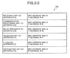
- Fig. 2-2 is a list of addresses of configurations. As depicted in Fig. 2-2 , in a list 230, an address (for example, an IP address or an MAC address) is set that designates each of the components as the transmission source or a transmission destination of transmission data, for each of the components that functions as an interface when data is transmitted or received. In practice, addresses are also set for each of the relay apparatuses R1, R2, and R4 described hereinafter. However, the embodiment does not include any process to designate the addresses of the relay apparatuses R1, R2, and R4 and therefore, representation of such addresses is omitted.
- an address for example, an IP address or an MAC address
- the transmission data transmitted from the communication terminal apparatus 130 is information having set therein a router Z connected to the tunneling apparatus 120 as its transmission destination.
- the tunneling apparatus 120 and the router Z are connected by I/F (interface) units 123 and 124.
- the bidirectional communication network that transmits the transmission data from the communication terminal apparatus 130 to the tunneling apparatus 120 is represented as a network 220 (corresponding to the IPv6 relaying network 140b).
- the relay apparatuses R1 and R2 are disposed in the network 210 and the relay apparatuses R3 and R4 are disposed in the network 220.
- the receiving unit 132 of the communication terminal apparatus 130 receives distribution data (SO) from the tunneling apparatus 120.
- the user of the communication terminal apparatus 130 transmits arbitrary transmission data to a distributing unit 122 that is the distribution source as a response to the distribution data.
- the data that the OS/application unit 131 has accepted is transmitted as the transmission data.
- the transmission data is output to the receiving unit 132 that has received the distribution data from the OS/application unit 131 (S1).
- the communication terminal apparatus 130 realizes bidirectional communication using the network that uses the UDLR.
- the receiving unit 132 and the distributing unit 122 each execute unidirectional communication.
- the units 132 and 122 seem to function as an interface that executes bidirectional communication. Therefore, the OS/application unit 131 executes the same processes as those executed when the OS/applicatior unit 131 is connected to an interface that executes bidirectional communication.
- the receiving unit 132 executes a process to transmit the transmission data input from the OS/application unit 131, to the tunneling apparatus 120. More specifically, to use the network 220 as a virtual network to transmit a response, the receiving unit 132 outputs the transmission data to the communication processing unit 133 (S2).
- the communication processing unit 133 includes a detecting unit 134, a setting unit 135, an error processing unit 136, and an I/F (interface) unit 137.
- the communication processing unit 133 transmits the transmission data from the I/F unit 137 to the network 220 (S3).
- the transmission data is sent to the tunneling apparatus 120 through the relay apparatuses R3 and R4.
- the relay apparatus R3 detects that the packet size of the transmission data exceeds the MTU, and an error message "Packet Too Big" is transmitted to the I/F unit 137 of the communication terminal apparatus 130 (S4).
- the communication processing unit 133 receives the error message through the I/F unit 137.
- the detecting unit 134, the setting unit 135, and the error processing unit 136 execute an error notification process.
- the detecting unit 134 first detects the error message (S5).
- the setting unit 135 sets data that is formed by including the error message in the transmission data, as new transmission data (S6).
- the error processing unit 136 finally executes a process of resolving the error detected by the relay apparatus R3, for the new transmission data set by the setting unit 135.
- a process of adjusting the packet size such that the transmission data has the capacity equal to or smaller than the capacity of the MTU, is executed.
- the process of resolving the error is a process of varying the packet size such that the capacity of the transmission data becomes equal to or smaller than the MTU, because the detecting unit 134 has detected the message "Packet Too Big".
- the error message "Packet Too Big” includes information that indicates the MTU of the network 220 and therefore, the packet size may be adjusted referring only to this information.
- the transmission data for which the process of resolving the error is executed by the error processing unit 136 is output again to the I/F unit 137 and is transmitted from the I/F unit 137 to the network 220 (S7).
- the transmission data having incorporated therein the error message is transmitted to the tunneling apparatus 120 through the relay apparatuses R3 and R4.
- the tunneling apparatus 120 receives the transmission data using the receiving unit 121.
- the receiving unit 121 refers to the address attached to the transmission data received and outputs the transmission data to the distributing unit 122 that is the transmission destination (S8).
- the distributing unit 122 distributes this transmission data to the communication terminal apparatus 130 as distribution data (S9).
- the distributing unit 122 refers to identification information (for example, an address) of the transmission destination of the transmission data and distributes the transmission data such that the distribution data reaches only the communication terminal apparatus 130.
- the distributing unit 122 of the tunneling apparatus 120 distributes the distribution data (for example, the distribution at S0), numerous unspecified communication terminal apparatuses 130 are distribution destinations.
- distribution limited to the communication terminal apparatus 130 that is the transmission destination of the transmission data is executed to notify the apparatus 130 of the error message. Any approach may be used to execute the limited distribution.
- the receiving unit 132 of the communication terminal apparatus 130 receives from the tunneling apparatus 120, the distribution data having incorporated therein the error message, the receiving unit 132 extracts the error message from the distribution data.
- the receiving unit 132 adjusts the packet size of the transmission data according to the MTU included in the extracted error message "Packet Too Big".
- the processes to give notification of the error are executed in the communication terminal apparatus 130 and the tunneling apparatus 120. Therefore, error notification may be executed even using a network configured by the UDLR such that an error message is reflected on the network.
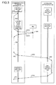
- Fig. 3 is a sequence chart of a transmission route of transmission data.
- transmission data 400 is input into the receiving unit 132 of the communication terminal apparatus 130.
- the transmission data 400 is the data accepted by the OS/application unit 131 depicted in Fig. 2-1 .
- Fig. 4 is a diagram of a configuration of the frame of the transmission data 400. It is assumed that the transmission data 400 is information to be transmitted to the router Z. Therefore, as depicted in Fig. 4 , the transmission data 400 includes a user data packet 401, an IP packet 402, and an MAC packet 403.
- the user data packet 401 is configured by data that is created by a user of the communication terminal apparatus 130.
- the data that is created by a user may be text data or may be video image data or music data, and the type of data is irrelevant.
- the data is not limited to data created by the communication terminal apparatus 130 and may be data prepared in advance.
- the IP packet 402 stores therein the IP address of the transmission source and the IP address of the transmission destination of the transmission data 400.
- An IP address is an address set in advance in each component that functions as an interface when data is transmitted or received. More specifically, the IP packet 402 is configured by the IP address (Src: IP-A) of the receiving unit 132 of the communication terminal apparatus 130 that is the transmission source, and the IP address (Dst: IP-Z) of the router Z that is the transmission destination.
- the MAC packet 403 stores therein the MAC address of the transmission source and the MAC address of the transmission destination of the transmission data 400. More specifically, the MAC packet 403 is configured by the MAC address (Src: MAC-A) of the receiving unit 132 of the communication terminal apparatus 130 that is the transmission source, and the MAC address (Dst: MAC-Z) of the router Z that is the transmission destination.
- Src MAC-A
- Dst MAC-Z
- the relay apparatuses R1 and R2 are not connected and the receiving unit 132 of the communication terminal apparatus 130 and the I/F unit 124 of the router Z are on the same segment.
- the address of the router Z itself is used as the MAC address that represents the transmission destination.
- the receiving unit 132 has set therein in advance the MTU that is the criterion and the packet size is adjusted to be the maximum size according to the MTU.
- the transmission data 400 is subject to encapsulation by the receiving unit 132 to use the UDLR. and becomes transmission data 500.
- Fig. 5 is a diagram of the configuration of the frame of the transmission data 500. As depicted in Fig. 5 , the transmission data 500 includes the transmission data 400 to which an encapsulation header packet 501, an encapsulation IP packet 502, and an encapsulation MAC packet 503 are appended as packets concerning the encapsulation.
- the encapsulation header packet 501 is a packet indicating that the transmission data 400 is encapsulated. More specifically, for example, the encapsulation is executed using a GRE (Generic Routing Encapsulation) protocol, etc.
- GRE Generic Routing Encapsulation
- the encapsulation IP packet 502 is configured by IP addresses of the communication processing unit 133 that is the transmission source and the receiving unit 121 that is the transmission destination used when the encapsulation is executed.
- the encapsulation MAC packet 503 stores therein the MAC address (Src: MAC-B) of the communication processing unit 133 that is the transmission source and the MAC address (Dst: MAC-M) of a receiving interface of R3 that is the nearest transmission destination used when the encapsulation is executed.
- the transmission data 400 is adjusted to have a packet size that is within the MTU (in this case, within 1,500 [bytes]).
- the transmission data 500 has a packet size larger than the MTU.
- This increased-portion of the packet size generated by the encapsulation is one factor that causes the packet size to exceed the MTU.
- the transmission data 500 is transmitted from the I/F unit 137 of the communication processing unit 133 to the network 220.
- the relay apparatus R3 detects that the transmission data 500 exceeds the MTU.
- Transmission data 600 including the error message "Packet Too Big” is returned from the relay apparatus R3 to the I/F unit 137 of the communication processing unit 133.
- Fig. 6 is a diagram of a configuration of the frame of the transmission data 600.
- the transmission data 600 is configured by the transmission data 500 appended with an error message packet 601 and a transmission destination IP address packet 602 to return the transmission data 500 to the communication processing unit 133 of the communication terminal apparatus 130.
- the packet size of the entire transmission data 600 is adjusted according to the MTU such that the transmission data 600 may be transmitted by the relay apparatus R3 to the network 220. More specifically, the adjustment is a process of reducing the packet size to a size equal to or smaller than the MTU. (1,500 [bytes]) by deleting a portion of the user data packet 401.
- the detecting unit 134 detects that the transmission data 600 is a packet encapsulated using the GRE protocol, etc. and is data that includes the error message packet 601.
- the detecting unit 134 detects the transmission data 600 as data that includes an error message, the detected data is set by the setting unit 135 as new transmission data.
- the communication processing unit 133 extracts the MTU included in the error message packet 601 and sets the extracted MTU to be the MTU of the network 220.
- the communication processing unit 133 progresses to a process to transmit the new transmission data.
- New transmission data 700 is created from the transmission data 600 based on the MTU( ⁇ ) calculated.
- Fig. 7 is a diagram of a configuration of the frame of the transmission data 700.
- the packet size is also adjusted by properly deleting the user data packet 401.
- the addresses of the transmission destinations of an IP address packet 702 and an MAC address packet 703 are set to be the addresses corresponding to the receiving unit 132 of the communication terminal apparatus 130 (IP address: IP-A, MAC address: MAC-A).
- the addresses of the transmission sources of the IP address packet 702 and the MAC address packet 703 of the transmission data 700 are set to be the addresses of the relay apparatus R3 (IP address: IP-M, MAC address: MAC-M) that has returned the transmission data 600 including the error message "Packet Too Big" to the I/F unit 137 of the communication processing unit 133 (see Fig. 6 ), or the addresses of the router Z (IP address: IP-Z, MAC address: MAC-Z).
- Encapsulation is again executed for the transmission data 700 created as described above to transmit the data 700 from the network 220 to the tunneling apparatus 120.
- the transmission data encapsulated by the error processing unit 136 has the configuration of transmission data 800 described hereinafter.
- the encapsulation executed again may be executed by the error processing unit 136 as one method, this encapsulation may also be executed utilizing a processing method of encapsulating an ordinary packet.
- Fig. 8 is a diagram of a configuration of the frame of the transmission data 800.
- the transmission data 800 is configured by the transmission data 500 added again with the packets (the encapsulation header packet 501, the encapsulation IP packet 502, and the encapsulation MAC packet 503) concerning the encapsulation that are added to the transmission data 500 depicted in Fig. 5 .
- the transmission data 800 processed by the error processing unit 136 is transmitted from the I/F unit 137 to the network 220.
- the transmission data 800 is received by the receiving unit 121 of the tunneling apparatus 120.
- the receiving unit 121 decapsulates the encapsulation of the transmission data 800 received, and extracts transmission data 900.
- Fig. 9 is a diagram of a configuration of the frame of the transmission data 900.
- the transmission data 900 is configured by removing the packets (the encapsulation header packet 501, the encapsulation IP packet 502, and the encapsulation MAC packet 503) concerning the encapsulation, from the transmission data 800. That is, the transmission data 900 has the same configuration as that of the transmission data 700.
- the receiving unit 121 executes a process to distribute the transmission data 900 to the receiving unit 132 of the communication terminal apparatus 130 that the addresses represent. More specifically, the receiving unit 121 outputs the transmission data 900 to the distributing unit 122.
- the distributing unit 122 using the network 210, distributes the transmission data 900 to the receiving unit 132 of the communication terminal apparatuses 130 having the destination addresses that are set in the packet.
- the receiving unit 132 of the communication terminal apparatus 130 uniquely receives distributed data (the transmission data 900) distributed from the network 210.
- the receiving unit 132 receives the error message "Packet Too Big" transmitted from the relay apparatus R3, changes the value of the MTU for the network 210 to the MTU( ⁇ ), and makes settings to transmit to the router Z, the transmission data of a packet size corresponding to the resulting MTU.
- a relay apparatus may assuredly give notification of an error via an error message regardless of the network configuration.
- the receiving unit 132 that is notified of an error transmits again the transmission data to the distributing unit 122
- the receiving unit 132 changes the content of the transmission data such that the size of the transmission data becomes equal to or smaller than the MTU. More specifically, the receiving unit 132 executes an adjustment such that the size of each frame becomes equal to or smaller than the MTU by deleting or dividing the capacity of the user data packet 401 of the transmission data 400 depicted in Fig. 4 .
- the MTU of the error message received by the receiving unit 132 of the communication terminal apparatus 130 may be set in the OS/application unit 131.
- the OS/application unit 131 divides the transmission data into capacities that each are the MTU, sequentially outputs the divided transmission data to be transmitted to the tunneling apparatus 120.
- the MTU is the packet size that is reduced in advance by the amount of the increased-portion. That is, exceeding the MTU due to the encapsulation may be prevented even using a response that uses the UDLR. Therefore, the MTU is set to be the largest communicable packet size and the transmission data may efficiently be transmitted.
- the value of the MTU of a network varies for each connection as in the embodiment even when the same communication terminal apparatus transmits data. Therefore, even when the MTU is set once by the above error notification process, the same process may be executed for each connection.
- the MTU set once using the error message may be stored and used as the initial value of the packet size of transmission data for the next session of transmission.
- the MTU in the previous session of transmission is used as the initial value as described, depending on the network connected, the MTU may become smaller each time the error notification process is repeated and as a result, the MTU may converge to the smallest MTU. Therefore, a setting of using the previous MTU as the initial value and a setting of musing an MTU of a relatively large value as the initial value may be used in parallel.
- the error notification method explained in the present embodiment may be implemented by a computer, such as a personal computer and a workstation, executing a program that is prepared in advance.
- the program is recorded on a computer-readable recording medium such as a hard disk, a flexible disk, a CD-ROM, an MO, and a DVD, and is executed by being read out from the recording medium by a computer.
- the program may be distributed through a network such as the Internet.
- the communication terminal apparatus, the distribution apparatus, the error notification method, and the error notification program according to the present invention are useful for transmission and reception of data using unidirectional communication such as broadcasting and in particular, are suitable for error notification between networks configured using the UDLR.
Landscapes
- Engineering & Computer Science (AREA)
- Computer Networks & Wireless Communication (AREA)
- Signal Processing (AREA)
- Data Exchanges In Wide-Area Networks (AREA)
- Mobile Radio Communication Systems (AREA)
Abstract
A communication terminal apparatus (130) includes a receiving unit (132) that receives distribution data distributed through a unidirectional communication network (210), an OS/application unit (131) that accepts transmission data to a tunneling apparatus (120), and a communication processing unit (133) that transmits the transmission data to a bidirectional communication network (220). When the communication processing unit (133) detects an error message of an encapsulated packet from the network (220) using a detecting unit (134), a setting unit (135) sets new transmission data that includes the error message. An error processing unit (136) subjects the transmission data to a process of resolving the error and thereafter, the transmission data is again transmitted to the network (220) to use the transmission data as distribution data from the tunneling apparatus (120).
Description
- The present invention relates to a communication terminal apparatus that receives using a unidirectional communication network and that transmits using a bidirectional communication network, a distribution apparatus that distributes distribution data using a unidirectional communication network and that receives transmission data from each terminal being a distribution destination of the distribution data using a bidirectional communication network, and an error notification method and an error notification program of the above apparatuses.
- Conventionally, to transmit and receive data using a network such as the Internet, connection to a communication counterpart terminal apparatus is established through a LAN (Local Area Network) or a WAN (Wide Area Network) that is configured according to any one of various standards such as Ethernet (a registered trade mark), an FDDI (Fiber-Distributed Data Interface), and an ATM (Asynchronous Transfer Mode).
- A given relay apparatus such as a router is equipped between networks. The relay apparatus has a function of monitoring whether transmission data transmitted to a network is transmittable. Therefore, when the relay apparatus finds an error in the transmission data, the relay apparatus transmits an error message corresponding to the content of the error to a communication terminal apparatus that is the transmission source of the transmission data.
- An error message may be, for example, a packet too big message, a destination unreachable message, a time exceeded message, and a parameter problem message. The details of processing for using a network based, in particular, on the IPv6 (Internet Protocol Version 6) will be described taking an example where a packet-capacity exceeded message is transmitted from a relay apparatus.
- As described, to transmit and receive data between given terminal apparatuses using the Internet, multiple networks must be passed through using relay apparatuses. The networks each have set therein a permissible data size that is transmittable for one packet of transmission. This permissible amount is generally referred to as "MTU (Maximum Transmission Unit)". When multiple networks are passed through to transmit and receive data between communication terminal apparatuses, a terminal apparatus for transmission must adjust the capacity of transmission data such that the transmission data may be transferred through the network having the smallest MTU.
-
Fig. 10 is a diagram for explaining a monitoring process of transmission data by a relay apparatus. The relay apparatus not only relays between networks but also monitors the capacity of transmission data such that a terminal apparatus for transmission may transmit transmission data of a capacity corresponding to the MTU of a network. - As depicted in
Fig. 10 , two networks, a network A and a network B, are configured between twocommunication terminal apparatuses communication terminal apparatus 1010 is a terminal for transmission, thecommunication terminal apparatus 1000 is a terminal for reception, and the MTU of the networks A and B is 1,500 [bytes]. - To transmit transmission data from the
communication terminal apparatus 1010, a case is tentatively assumed first where the transmission data is output from anapplication unit 1011 to communication processing interfaces (I/Fs) 1012A and 1012B (S10). A process of actually outputting packets using application software simultaneously to two interfaces is not common. However, to describe the relation between the transmission data and the MTU, a case where the transmission data is output to the communication processing interfaces (I/Fs) 1012A and 1012B is temporarily assumed and will be described for convenience. - In this example, transmission data of a capacity of 1,500 [bytes] or less, representing packet size, is output to the communication processing interface (I/F) 1012A and transmission data of a packet size of 1,500 [bytes] or larger is output to the communication processing interface (I/F) 1012B.
- The transmission data transmitted from the communication processing interface (I/F) 1012A to the network A has a capacity equal to or less than the MTU and therefore, the transmission data is received by the communication processing interface (I/F) 1001A of the
communication terminal apparatus 1000 for reception through the relay apparatuses R2 and R1 (S11). - On the other hand, the transmission data transmitted from the communication processing interface (I/F) 1012B to the network B has a capacity exceeding the MTU and the relay apparatus R3 detects that the capacity is larger than the MTU (S12). Hence, the transmission data is not transmitted to the communication processing interface (I/F) 1001B of the
communication terminal apparatus 1000 and instead, an error message "Packet Too Big" indicating that the transmission data exceeds the MTU is transmitted to the communication terminal apparatus 1010 (S13). - When the communication processing interface (I/F) 1012B of the
communication terminal apparatus 1010 receives the error message "Packet Too Big" from the network B, the interface (I/F) 1012B reduces the packet size of the transmission data. This series of processing is known as "Path MTU Discovery (RFC 1981)" (see, for example, NonPatent Literature 1). - Recently, transmission and reception of data using a network that uses UDLR (Uni-Directional Link Routing) has also been realized.
Fig. 11 is a diagram for explaining a monitoring process of a relay apparatus in a network using the UDLR. - As depicted in
Fig. 11 , the network using the UDLR includes adistribution apparatus 1100 that distributes data (distribution data) using a unidirectional communication network, and acommunication terminal apparatus 1110 that receives the transmission data. Thedistribution apparatus 1100 and thecommunication terminal apparatus 1110 are connected to a unidirectional communication network C dedicated for distribution, and a bidirectional communication network D (a normal network) used for transmitting data from thecommunication terminal apparatus 1110 to thedistribution apparatus 1100. - When the distribution data is distributed from the
distribution apparatus 1100 to thecommunication terminal apparatus 1110, the distribution data is output from a distributing interface (I/F) 1101 to the unidirectional communication network C (S00). From thedistribution apparatus 1100, the distribution data may be distributed to a specific communication terminal apparatus or may be distributed to multiple communication terminal apparatuses as a broadcast wave. - The
communication terminal apparatus 1110 receives the distribution data using a receiving interface (I/F) 1112. In a network using the UDLR, to transmit a response to thedistribution apparatus 1100, transmission data is output from an OS/application unit 1111 to the receiving interface (I/F) 1112 that is connected to the unidirectional communication network C (S20). To transmit as a response to thedistribution apparatus 1100, the transmission data that is transmitted as a response to the unidirectional communication network C, the receiving interface (I/F) 1112 realizes a virtual bidirectional communication network by transmitting the transmission data to the bidirectional communication network D. Therefore, the receiving interface (I/F) 1112 applies a given process to the transmission data and outputs the processed transmission data to a communication processing interface (I/F) 1113 (S21). - The communication processing interface (I/F) 1113 transmits the transmission data to the bidirectional communication network D. Here, when the transmission data has a capacity equal to or less than the MTU, the transmission data is transmitted to the
distribution apparatus 1100 through the relay apparatuses R3 and R4. - Nonpatent Literature 1: Izumi, Miki, "Serial Article: Invitation to IPv6 Networks (No. 3) 'Header Format of IPv6'", [online], October 5, 2001, Research Institute for Internet Strategies, Inc., [Retrieved on July 7, 2006], on the Internet <URL:
- http://www.atmarkit.co.jp/fnetwork/rensai/ipv6-03/ipv6-01.html>
- However, the above monitoring process using the relay apparatuses does not function normally when bidirectional communication is executed using a network for unidirectional communication.
- More specifically, when transmission data having a capacity exceeding the MTU is transmitted (S22) in
Fig. 11 , the relay apparatus R3 detects that the transmission data exceeds the MTU similarly to the example depicted inFig. 10 . An error message "Packet Too Big" is transmitted from the relay apparatus R3 to the communication terminal apparatus 1110 (S23). Therefore, the transmission data is not transmitted to a receiving interface (I/F) 1102 of thedistribution apparatus 1100. - The error message "Packet Too Big" is transmitted to the communication processing interface (I/F) 1113 of the
communication terminal apparatus 1110. In this manner, the communication processing interface (I/F) 1113 receives the message "Packet Too Big". However, in the UDLR network, the interface that actually outputs the transmission data from the apparatus is the receiving interface (I/F) 1112. Therefore, the message "Packet Too Big" does not reach the receiving interface (I/F) 1112. - Accordingly, the OS/
application unit 1111 recognizes the MTU of the bidirectional communication network D and reduces the packet size of the transmission data that is directly transmitted to the bidirectional communication network D. However, when the transmission data is to be transmitted from thecommunication terminal apparatus 1110 to the unidirectional communication network C, the OS/application unit 1111 recognizes this transmission data as transmission data to be transmitted from the receiving interface (I/F) 1112 to the unidirectional communication network C and accordingly executes processing. Thus, the OS/application unit 1111 does not reflect at all the message "Packet Too Big" that arrives at the communication processing interface (I/F) 1113 and the OS/application unit 1111 inevitably outputs, consecutively, transmission data having a packet size exceeding the MTU to the receiving interface (I/F) 1112. In this manner, in a UDLR network, "Path MTU Discovery" do not function. - As described, in a UDLR network, error messages by a relay apparatus are not reflected at the
communication terminal apparatus 1110. Therefore, in a conventional UDLR network, to prevent the capacity of any transmission data from exceeding the MTU, transmission is executed using the smallest value set as the MTU, as the capacity of the transmission data. Hence, only transmission data having the smallest capacity may be handled regardless of the actual MTU of a network and therefore, a problem has arisen in that the efficiency of the communication is poor. - Even when an error message other than the packet too big message is transmitted, the error message does not reach the interface (in
Fig. 11 , receiving interface (I/F)) 1112 that has output the transmission data causing the error. Therefore, a problem has arisen in that the error will not be resolved. - To solve the above problems associated with the conventional techniques, an object of the present invention is to provide a communication terminal apparatus, a distribution apparatus, an error notification method, and an error notification program that provide notification of an error to an interface that is the transmission source transmitting transmission data from which the error is detected, enabling the error to be resolved, even using a network that is configured to receive data from a communication counterpart using a unidirectional communication network.
- To solve the problems above and achieve an object, a communication terminal apparatus according to the invention of
claim 1 receives using a unidirectional communication network and transmits using a bidirectional communication network. The communication terminal apparatus includes a receiving unit that receives distribution data distributed through the unidirectional communication network; an accepting unit that accepts transmission data to be transmitted to a distribution source of the distribution data received by the receiving unit; and a communication processing unit that transmits the transmission data accepted by the accepting unit to the bidirectional communication network. The communication processing unit includes a detecting unit that detects an error message concerning the transmission data from the bidirectional communication network; a setting unit that sets the transmission data that includes the error message detected by the detecting unit, to be new transmission data; an error processing unit that subjects the new transmission data set by the setting unit to a process of resolving an error corresponding to the error message; and a transmitting unit that transmits the transmission data whose error has been resolved by the error processing unit to the bidirectional communication network to use the transmission data as the distribution data from the distribution source. - According to the invention of
claim 1, the error notification does not end with a transmission of an error message to a unit unrelated to the transmission data setting as is conventionally executed, rather the transmission data is processed as new transmission data that includes the error message. The new transmission data is transmitted to the distribution apparatus to be distributed from the distribution apparatus to the transmission source as distribution data. - Further a distribution apparatus according to the invention of
claim 5 includes a distributing unit that distributes distribution data using a unidirectional communication network; and a receiving unit that receives transmission data from a terminal that is a distribution destination of the distribution data, using a bidirectional communication network. The distributing unit distributes the transmission data as the distribution data to a terminal that is a transmission source of transmission data that includes an error message received by the receiving unit, when the receiving unit receives transmission data that includes an error message from a terminal. - According to the invention of
claim 5, when the transmission data having incorporated therein the error message is received, the transmission data received is distributed as distribution data to a terminal that is the transmission source of the transmission data. Therefore, the error message is directly distributed to the terminal that is the transmission source of the transmission data corresponding to the error message and thereby, enabling notification of the error. - An error notification method according to the invention of claim 7 is that of a communication terminal apparatus that receives by a unidirectional communication network and transmits by a bidirectional communication network. The error notification method includes a receiving step of receiving, distribution data distributed through the unidirectional communication network; an accepting step of accepting transmission data to be transmitted to a distribution source of the distribution data received at the receiving step; and a first transmitting step of transmitting the transmission data accepted at the accepting step to the bidirectional communication network; a setting step of setting, when an error message is detected with respect to the transmission data from the bidirectional communication network, the transmission data including the detected error message to be new transmission data; an error processing step of subjecting the new transmission data set at the setting step to a process of resolving an error corresponding to the error message; and a second transmitting step of transmitting the transmission data whose error has been resolved at the error processing step, to the bidirectional communication network to use the transmission data as the distribution data from the distribution source.
- According to the invention of claim 7, the error notification does not end with a transmission of an error message to a unit unrelated to the transmission data setting as is conventionally executed, rather the transmission data is processed as new transmission data that includes the error message. After processing, the new transmission data is transmitted to the distribution apparatus to be distributed from the distribution apparatus to the transmission source as distribution data.
- An error notification method according to the invention of claim 8, includes a receiving step of receiving via a bidirectional communication network and by a transmitting unit of a distribution apparatus, transmission data from a terminal that is a distribution destination of the distribution data; and a distributing step of distributing via a unidirectional communication network, by a distribution unit of the distribution apparatus and as distribution data, the transmission data to the terminal that is a transmission source of the transmission data received at the receiving step and inclusive of an error message.
- According to the invention of claim 8, when the transmission data having incorporated therein the error message is received, the transmission data received is distributed as distribution data to a terminal that is the transmission source of the transmission data. Therefore, the error message is directly distributed to the terminal that is the transmission source of the transmission data corresponding to the error message and thereby, enabling notification of the error.
- An error notification program according to
claim 9 causes a computer to execute the error notification method recited in claim 7 or 8. - According to the communication terminal apparatus, the distribution apparatus, the error notification method, and the error notification program of the present invention, an effect is achieved in that error notification may be provided to an interface that is the transmission source transmitting transmission data from which the error is detected and thereby, the error may be resolved even using a network that is configured to receive data from a communication counterpart using a unidirectional communication network.
-
-
Fig. 1 is a diagram for explaining a network configuration according to the present embodiment; -
Fig. 2-1 is a diagram for explaining an error message notification process; -
Fig. 2-2 is a list of addresses of configurations; -
Fig. 3 is a sequence chart of a transmission route of transmission data; -
Fig. 4 is a diagram of a configuration a frame oftransmission data 400; -
Fig. 5 is a diagram of a configuration of a frame oftransmission data 500; -
Fig. 6 is a diagram of a configuration of a frame oftransmission data 600; -
Fig. 7 is a diagram of a configuration of a frame oftransmission data 700; -
Fig. 8 is a diagram of a configuration of a frame oftransmission data 800; -
Fig. 9 is a diagram of a configuration of a frame oftransmission data 900; -
Fig. 10 is a diagram for explaining a monitoring process of transmission data by a relay apparatus; and -
Fig. 11 is a diagram for explaining a monitoring process of a relay apparatus in a network using the UDLR. -
- 110
- application server
- 120
- tunneling apparatus
- 121
- receiving unit
- 122
- distributing unit
- 123, 124
- I/F (interface) unit
- 130
- communication terminal apparatus
- 131
- OS/application unit
- 132
- receiving unit
- 133
- communication processing unit
- 134
- detecting unit
- 135
- setting unit
- 136
- error processing unit
- 137
- I/F (interface) unit
- 140a
- unidirectional communication network
- 140b
- IPv6 relaying network
- R1, R2, R3, R4
- relay apparatus
- Z
- router
- A preferred embodiment of a communication terminal apparatus, a distribution apparatus, an error notification method, and an error notification program according to the present invention will be described in detail with reference to the accompanying drawings.
- A network configuration according to the present embodiment will be described.
Fig. 1 is a diagram for explaining a network configuration according to the embodiment. As depicted inFig. 1 , anetwork configuration 100 according to the embodiment includes anapplication server 110, atunneling apparatus 120 that functions as a distribution apparatus, and acommunication terminal apparatus 130. Thenetwork configuration 100 uses the UDLR and therefore, aunidirectional communication network 140a that is used when distribution data is distributed from thetunneling apparatus 120 to thecommunication terminal apparatus 130, and anIPv6 relaying network 140b that is bidirectional communicable and used when transmission data is transmitted from thecommunication terminal apparatus 130 to thetunneling apparatus 120 are connected between thetunneling apparatus 120 and thecommunication terminal apparatus 130. - In the
network configuration 100, theapplication server 110 delivers to thetunneling apparatus 120, application data that is to be distributed to thecommunication terminal apparatus 130. More specifically, theapplication server 110 outputs the application data to thetunneling apparatus 120. Output to thetunneling apparatus 120 may be by a physical line or a wireless means. - The "application data" is software data designed according to various purposes and is distributed to the
communication terminal apparatus 130. More specifically, the application data is software that causes thecommunication terminal apparatus 130 to execute a specific function such as given calculation, position searching, game playing, or playing of contents, or is data of contents to be played by thecommunication terminal apparatus 130. The content of the application data is not particularly limited. - The application data may be distributed to all the
communication terminal apparatuses 130 within a distribution area of thetunneling apparatus 120. When the distribution data is distributed, thetunneling apparatus 120 may distribute the distribution data only to a givencommunication terminal apparatus 130 by setting identification information such as an address or distribution conditions. When thecommunication terminal apparatus 130 receives the application data, thecommunication terminal apparatus 130 may transmit arbitrary transmission data to thetunneling apparatus 120 that is the distribution source using theIPv6 relaying network 140b. - The
tunneling apparatus 120 distributes to thecommunication terminal apparatuses 130 the application data delivered from theapplication server 110 as distribution data. More specifically, thetunneling apparatus 120 distributes (broadcasts) the distribution data to thecommunication terminal apparatuses 130 using theunidirectional communication network 140a. Thetunneling apparatus 120 also accepts the transmission data transmitted as a response from thecommunication terminal apparatus 130 that receives the distribution data. - The
communication terminal apparatus 130 receives the distribution data from thetunneling apparatus 120. Thecommunication terminal apparatus 130 transmits arbitrary transmission data as a response to thetunneling apparatus 120 using theIPv6 relaying network 140b. More specifically, thecommunication terminal apparatus 130 includes an OS/application unit 131, a receivingunit 132, and acommunication processing unit 133. - The OS/
application unit 131 functions as an interface for a user of thecommunication terminal apparatus 130. The OS/application unit 131 accepts transmission data to be transmitted from the user to thetunneling apparatus 120. The receivingunit 132 is connected to theunidirectional communication network 140a and receives distribution data distributed from thetunneling apparatus 120. - The
communication processing unit 133 transmits the transmission data received by the OS/application unit 131 to theIPv6 relaying network 140b that is a bidirectional communication network. When an error message with respect to the transmission data is transmitted as a response from theIPv6 relaying network 140b, thecommunication processing unit 133 detects the error message. When thecommunication processing unit 133 detects the error message, thecommunication processing unit 133 executes a given notifying process to notify the receivingunit 132 of the error message detected. The content of the notifying process of the error message will be described in detail with reference toFig. 2 hereinafter. - A process by the
communication terminal apparatus 130 executed when an error message is transmitted from theIPv6 relaying network 140b of thenetwork configuration 100 depicted inFig. 1 will be described. In the embodiment, an example will be described where an error message "Packet Too Big" is transmitted to provide notification that transmission data of a capacity exceeding the MTU representing the capacity transmittable in a network, has been transmitted. -
Fig. 2-1 is a diagram for explaining the error message notification process.Fig. 2-1 depicts the connection between thetunneling apparatus 120 and thecommunication terminal apparatus 130. The unidirectional communication network that distributes the application data (distribution data) from thetunneling apparatus 120 is depicted as a network 210 (corresponding to theunidirectional communication network 140a). -
Fig. 2-2 is a list of addresses of configurations. As depicted inFig. 2-2 , in alist 230, an address (for example, an IP address or an MAC address) is set that designates each of the components as the transmission source or a transmission destination of transmission data, for each of the components that functions as an interface when data is transmitted or received. In practice, addresses are also set for each of the relay apparatuses R1, R2, and R4 described hereinafter. However, the embodiment does not include any process to designate the addresses of the relay apparatuses R1, R2, and R4 and therefore, representation of such addresses is omitted. - It is assumed that the transmission data transmitted from the
communication terminal apparatus 130 is information having set therein a router Z connected to thetunneling apparatus 120 as its transmission destination. As depicted inFig. 2-1 , thetunneling apparatus 120 and the router Z are connected by I/F (interface)units - The bidirectional communication network that transmits the transmission data from the
communication terminal apparatus 130 to thetunneling apparatus 120 is represented as a network 220 (corresponding to theIPv6 relaying network 140b). As an example, the relay apparatuses R1 and R2 are disposed in thenetwork 210 and the relay apparatuses R3 and R4 are disposed in thenetwork 220. - The receiving
unit 132 of thecommunication terminal apparatus 130 receives distribution data (SO) from thetunneling apparatus 120. The user of thecommunication terminal apparatus 130 transmits arbitrary transmission data to a distributingunit 122 that is the distribution source as a response to the distribution data. At this time, the data that the OS/application unit 131 has accepted is transmitted as the transmission data. The transmission data is output to the receivingunit 132 that has received the distribution data from the OS/application unit 131 (S1). - The
communication terminal apparatus 130 realizes bidirectional communication using the network that uses the UDLR. In practice, the receivingunit 132 and the distributingunit 122 each execute unidirectional communication. However, viewing the processes of the receivingunit 132 and the distributingunit 122 from the OS/application unit 131, theunits application unit 131 executes the same processes as those executed when the OS/applicatior unit 131 is connected to an interface that executes bidirectional communication. - The receiving
unit 132 executes a process to transmit the transmission data input from the OS/application unit 131, to thetunneling apparatus 120. More specifically, to use thenetwork 220 as a virtual network to transmit a response, the receivingunit 132 outputs the transmission data to the communication processing unit 133 (S2). - The configuration of the
communication processing unit 133 will be described. As depicted inFig. 2-1 , thecommunication processing unit 133 includes a detectingunit 134, asetting unit 135, anerror processing unit 136, and an I/F (interface)unit 137. When the transmission data is input from the receivingunit 132, thecommunication processing unit 133 transmits the transmission data from the I/F unit 137 to the network 220 (S3). - When the packet size of the transmission data transmitted from the I/
F unit 137 is equal to or smaller than the MTU of thenetwork 220, the transmission data is sent to thetunneling apparatus 120 through the relay apparatuses R3 and R4. However, when the packet size of the transmission data exceeds the MTU of thenetwork 220, the relay apparatus R3 detects that the packet size of the transmission data exceeds the MTU, and an error message "Packet Too Big" is transmitted to the I/F unit 137 of the communication terminal apparatus 130 (S4). - When the error message "Packet Too Brig" is transmitted from the relay apparatus R3, the
communication processing unit 133 receives the error message through the I/F unit 137. The detectingunit 134, thesetting unit 135, and theerror processing unit 136 execute an error notification process. The detectingunit 134 first detects the error message (S5). Thesetting unit 135 then sets data that is formed by including the error message in the transmission data, as new transmission data (S6). - The
error processing unit 136 finally executes a process of resolving the error detected by the relay apparatus R3, for the new transmission data set by thesetting unit 135. In the embodiment, because the message "Packet Too Big" is detected, a process of adjusting the packet size such that the transmission data has the capacity equal to or smaller than the capacity of the MTU, is executed. - In this example, the process of resolving the error is a process of varying the packet size such that the capacity of the transmission data becomes equal to or smaller than the MTU, because the detecting
unit 134 has detected the message "Packet Too Big". The error message "Packet Too Big" includes information that indicates the MTU of thenetwork 220 and therefore, the packet size may be adjusted referring only to this information. The transmission data for which the process of resolving the error is executed by theerror processing unit 136 is output again to the I/F unit 137 and is transmitted from the I/F unit 137 to the network 220 (S7). - The transmission data having incorporated therein the error message is transmitted to the
tunneling apparatus 120 through the relay apparatuses R3 and R4. Thetunneling apparatus 120 receives the transmission data using the receivingunit 121. The receivingunit 121 refers to the address attached to the transmission data received and outputs the transmission data to the distributingunit 122 that is the transmission destination (S8). - When the transmission data having incorporated therein the error message is input into the distributing
unit 122 from the receivingunit 121, the distributingunit 122 distributes this transmission data to thecommunication terminal apparatus 130 as distribution data (S9). When the distribution at S9 is executed, the distributingunit 122 refers to identification information (for example, an address) of the transmission destination of the transmission data and distributes the transmission data such that the distribution data reaches only thecommunication terminal apparatus 130. - As described, usually, when the distributing
unit 122 of thetunneling apparatus 120 distributes the distribution data (for example, the distribution at S0), numerous unspecifiedcommunication terminal apparatuses 130 are distribution destinations. However, in the distribution at S9, distribution limited to thecommunication terminal apparatus 130 that is the transmission destination of the transmission data is executed to notify theapparatus 130 of the error message. Any approach may be used to execute the limited distribution. - When the receiving
unit 132 of thecommunication terminal apparatus 130 receives from thetunneling apparatus 120, the distribution data having incorporated therein the error message, the receivingunit 132 extracts the error message from the distribution data. The receivingunit 132 adjusts the packet size of the transmission data according to the MTU included in the extracted error message "Packet Too Big". - As described, the processes to give notification of the error are executed in the
communication terminal apparatus 130 and thetunneling apparatus 120. Therefore, error notification may be executed even using a network configured by the UDLR such that an error message is reflected on the network. - To execute the error message notification process as depicted in
Fig. 2-1 , a given adjustment must be executed with respect to the transmission data. Hence, the details of the adjustment of the transmission data in the error message notification process will be described with reference toFigs. 3 to 9 . -
Fig. 3 is a sequence chart of a transmission route of transmission data. As depicted inFig. 3 ,transmission data 400 is input into the receivingunit 132 of thecommunication terminal apparatus 130. Thetransmission data 400 is the data accepted by the OS/application unit 131 depicted inFig. 2-1 . -
Fig. 4 is a diagram of a configuration of the frame of thetransmission data 400. It is assumed that thetransmission data 400 is information to be transmitted to the router Z. Therefore, as depicted inFig. 4 , thetransmission data 400 includes auser data packet 401, anIP packet 402, and anMAC packet 403. - The
user data packet 401 is configured by data that is created by a user of thecommunication terminal apparatus 130. The data that is created by a user may be text data or may be video image data or music data, and the type of data is irrelevant. The data is not limited to data created by thecommunication terminal apparatus 130 and may be data prepared in advance. - The
IP packet 402 stores therein the IP address of the transmission source and the IP address of the transmission destination of thetransmission data 400. An IP address is an address set in advance in each component that functions as an interface when data is transmitted or received. More specifically, theIP packet 402 is configured by the IP address (Src: IP-A) of the receivingunit 132 of thecommunication terminal apparatus 130 that is the transmission source, and the IP address (Dst: IP-Z) of the router Z that is the transmission destination. - The
MAC packet 403 stores therein the MAC address of the transmission source and the MAC address of the transmission destination of thetransmission data 400. More specifically, theMAC packet 403 is configured by the MAC address (Src: MAC-A) of the receivingunit 132 of thecommunication terminal apparatus 130 that is the transmission source, and the MAC address (Dst: MAC-Z) of the router Z that is the transmission destination. - To simply the explanation, in the embodiment, it is assumed that the relay apparatuses R1 and R2 are not connected and the receiving
unit 132 of thecommunication terminal apparatus 130 and the I/F unit 124 of the router Z are on the same segment. The address of the router Z itself is used as the MAC address that represents the transmission destination. The receivingunit 132 has set therein in advance the MTU that is the criterion and the packet size is adjusted to be the maximum size according to the MTU. - In the example depicted in
Fig. 2-1 , an example where the processing is executed assuming that the initial value of the MTU of each of thenetworks communication terminal apparatus 120 establishes a connection to another network and thereby, executes the UDLR, a different MTU may be set (the MTU may also be MTU=1,500 [bytes]). Therefore, each time a connection is established, the packet size is adjusted to be the largest size that matches the MTU set. - The
transmission data 400 is subject to encapsulation by the receivingunit 132 to use the UDLR. and becomestransmission data 500.Fig. 5 is a diagram of the configuration of the frame of thetransmission data 500. As depicted inFig. 5 , thetransmission data 500 includes thetransmission data 400 to which anencapsulation header packet 501, anencapsulation IP packet 502, and anencapsulation MAC packet 503 are appended as packets concerning the encapsulation. - The
encapsulation header packet 501 is a packet indicating that thetransmission data 400 is encapsulated. More specifically, for example, the encapsulation is executed using a GRE (Generic Routing Encapsulation) protocol, etc. - The
encapsulation IP packet 502 is configured by IP addresses of thecommunication processing unit 133 that is the transmission source and the receivingunit 121 that is the transmission destination used when the encapsulation is executed. Theencapsulation MAC packet 503 stores therein the MAC address (Src: MAC-B) of thecommunication processing unit 133 that is the transmission source and the MAC address (Dst: MAC-M) of a receiving interface of R3 that is the nearest transmission destination used when the encapsulation is executed. - The packet size of the appended
packet portions 501 to 503 of thetransmission data 500 is an increased-portion size that is the increased-portion size=α with respect to thetransmission data 400. As described, thetransmission data 400 is adjusted to have a packet size that is within the MTU (in this case, within 1,500 [bytes]). However, thetransmission data 400 is appended with the increased-portion size=α and becomes thetransmission data 500. As a result, thetransmission data 500 has a packet size larger than the MTU. This increased-portion of the packet size generated by the encapsulation is one factor that causes the packet size to exceed the MTU. The value of the increased-portion=α is stored in a memory, etc., such that the value may be used in error processing described hereinafter. - The
transmission data 500 is transmitted from the I/F unit 137 of thecommunication processing unit 133 to thenetwork 220. The relay apparatus R3 detects that thetransmission data 500 exceeds the MTU.Transmission data 600 including the error message "Packet Too Big" is returned from the relay apparatus R3 to the I/F unit 137 of thecommunication processing unit 133. -
Fig. 6 is a diagram of a configuration of the frame of thetransmission data 600. As depicted inFig. 6 , thetransmission data 600 is configured by thetransmission data 500 appended with anerror message packet 601 and a transmission destinationIP address packet 602 to return thetransmission data 500 to thecommunication processing unit 133 of thecommunication terminal apparatus 130. The packet size of theentire transmission data 600 is adjusted according to the MTU such that thetransmission data 600 may be transmitted by the relay apparatus R3 to thenetwork 220. More specifically, the adjustment is a process of reducing the packet size to a size equal to or smaller than the MTU. (1,500 [bytes]) by deleting a portion of theuser data packet 401. - When the
communication processing unit 133 receives thetransmission data 600 that is returned from the relay apparatus R3 by the I/F unit 137 (seeFig. 2-1 ), the detecting unit 134 (seeFig. 2-1 ) detects that thetransmission data 600 is a packet encapsulated using the GRE protocol, etc. and is data that includes theerror message packet 601. When the detectingunit 134 detects thetransmission data 600 as data that includes an error message, the detected data is set by thesetting unit 135 as new transmission data. - The
communication processing unit 133 extracts the MTU included in theerror message packet 601 and sets the extracted MTU to be the MTU of thenetwork 220. Thecommunication processing unit 133 progresses to a process to transmit the new transmission data. Theerror processing unit 136 extracts the increased-portion size=α added when the encapsulation is executed, from thetransmission data 500. Theerror processing unit 136 calculates a value by subtracting the increased-portion size=α from the value of the MTU extracted from theerror message packet 601 as the MTU(α) to be referred to when the receivingunit 132 outputs transmission data.New transmission data 700 is created from thetransmission data 600 based on the MTU(α) calculated. -
Fig. 7 is a diagram of a configuration of the frame of thetransmission data 700. As depicted inFig. 7 , anerror message packet 701 formed by rewriting the MTU (1,500 [bytes]) of theerror message packet 601 of thetransmission data 600 to MTU=MTU(α) is created and the packet size of theentire transmission data 700 is adjusted such that the MTU becomes MTU=MTU(α). In this case, the packet size is also adjusted by properly deleting theuser data packet 401. - When the
transmission data 700 is created, to distribute theerror message packet 701 to the receivingunit 132 of thecommunication terminal apparatus 130, the addresses of the transmission destinations of anIP address packet 702 and anMAC address packet 703 are set to be the addresses corresponding to the receivingunit 132 of the communication terminal apparatus 130 (IP address: IP-A, MAC address: MAC-A). - The addresses of the transmission sources of the
IP address packet 702 and theMAC address packet 703 of thetransmission data 700 are set to be the addresses of the relay apparatus R3 (IP address: IP-M, MAC address: MAC-M) that has returned thetransmission data 600 including the error message "Packet Too Big" to the I/F unit 137 of the communication processing unit 133 (seeFig. 6 ), or the addresses of the router Z (IP address: IP-Z, MAC address: MAC-Z). - Encapsulation is again executed for the
transmission data 700 created as described above to transmit thedata 700 from thenetwork 220 to thetunneling apparatus 120. The transmission data encapsulated by theerror processing unit 136 has the configuration oftransmission data 800 described hereinafter. However, although the encapsulation executed again may be executed by theerror processing unit 136 as one method, this encapsulation may also be executed utilizing a processing method of encapsulating an ordinary packet. -
Fig. 8 is a diagram of a configuration of the frame of thetransmission data 800. As depicted inFig. 8 , thetransmission data 800 is configured by thetransmission data 500 added again with the packets (theencapsulation header packet 501, theencapsulation IP packet 502, and the encapsulation MAC packet 503) concerning the encapsulation that are added to thetransmission data 500 depicted inFig. 5 . The increased-portion size of each of the packets is the increased-portion size=α, and the packet size of theentire transmission data 700 is MTU=MTU(α). Therefore, as a result, the packet size of theentire transmission data 800 is a size that is within the MTU that is MTU=1,500 [bytes]. - The
transmission data 800 processed by theerror processing unit 136 is transmitted from the I/F unit 137 to thenetwork 220. Thetransmission data 800 is received by the receivingunit 121 of thetunneling apparatus 120. The receivingunit 121 decapsulates the encapsulation of thetransmission data 800 received, and extractstransmission data 900. -
Fig. 9 is a diagram of a configuration of the frame of thetransmission data 900. As depicted inFig. 9 , thetransmission data 900 is configured by removing the packets (theencapsulation header packet 501, theencapsulation IP packet 502, and the encapsulation MAC packet 503) concerning the encapsulation, from thetransmission data 800. That is, thetransmission data 900 has the same configuration as that of thetransmission data 700. - The receiving
unit 121 extracts the addresses (Dst: IP=A, MAC-A) of the transmission destination that are set in theIP address packet 702 and theMAC address packet 703, from thetransmission data 900. The receivingunit 121 executes a process to distribute thetransmission data 900 to the receivingunit 132 of thecommunication terminal apparatus 130 that the addresses represent. More specifically, the receivingunit 121 outputs thetransmission data 900 to the distributingunit 122. The distributingunit 122, using thenetwork 210, distributes thetransmission data 900 to the receivingunit 132 of thecommunication terminal apparatuses 130 having the destination addresses that are set in the packet. - The receiving
unit 132 of thecommunication terminal apparatus 130 uniquely receives distributed data (the transmission data 900) distributed from thenetwork 210. As a result, the receivingunit 132 receives the error message "Packet Too Big" transmitted from the relay apparatus R3, changes the value of the MTU for thenetwork 210 to the MTU(α), and makes settings to transmit to the router Z, the transmission data of a packet size corresponding to the resulting MTU. - As described, according to the communication terminal apparatus, the distribution apparatus, the error notification method, and the error notification program, a relay apparatus may assuredly give notification of an error via an error message regardless of the network configuration. When the receiving
unit 132 that is notified of an error transmits again the transmission data to the distributingunit 122, the receivingunit 132 changes the content of the transmission data such that the size of the transmission data becomes equal to or smaller than the MTU. More specifically, the receivingunit 132 executes an adjustment such that the size of each frame becomes equal to or smaller than the MTU by deleting or dividing the capacity of theuser data packet 401 of thetransmission data 400 depicted inFig. 4 . - When transmission data of a packet size larger than the MTU is desired to be transmitted, the MTU of the error message received by the receiving
unit 132 of thecommunication terminal apparatus 130 may be set in the OS/application unit 131. In such an example, the OS/application unit 131 divides the transmission data into capacities that each are the MTU, sequentially outputs the divided transmission data to be transmitted to thetunneling apparatus 120. - Taking into account the increased-portion of the packet to be added due to the encapsulation, the MTU is the packet size that is reduced in advance by the amount of the increased-portion. That is, exceeding the MTU due to the encapsulation may be prevented even using a response that uses the UDLR. Therefore, the MTU is set to be the largest communicable packet size and the transmission data may efficiently be transmitted.
- The value of the MTU of a network varies for each connection as in the embodiment even when the same communication terminal apparatus transmits data. Therefore, even when the MTU is set once by the above error notification process, the same process may be executed for each connection.
- Further, the MTU set once using the error message may be stored and used as the initial value of the packet size of transmission data for the next session of transmission. When the MTU in the previous session of transmission is used as the initial value as described, depending on the network connected, the MTU may become smaller each time the error notification process is repeated and as a result, the MTU may converge to the smallest MTU. Therefore, a setting of using the previous MTU as the initial value and a setting of musing an MTU of a relatively large value as the initial value may be used in parallel.
- The error notification method explained in the present embodiment may be implemented by a computer, such as a personal computer and a workstation, executing a program that is prepared in advance. The program is recorded on a computer-readable recording medium such as a hard disk, a flexible disk, a CD-ROM, an MO, and a DVD, and is executed by being read out from the recording medium by a computer. The program may be distributed through a network such as the Internet.
- As described, the communication terminal apparatus, the distribution apparatus, the error notification method, and the error notification program according to the present invention are useful for transmission and reception of data using unidirectional communication such as broadcasting and in particular, are suitable for error notification between networks configured using the UDLR.
Claims (9)
- A communication terminal apparatus that receives using a unidirectional communication network and that transmits using a bidirectional communication network, comprising:a receiving unit that receives distribution data distributed through the unidirectional communication network;an accepting unit that accepts transmission data to be transmitted to a distribution source of the distribution data received by the receiving unit; anda communication processing unit that transmits the transmission data accepted by the accepting unit to the bidirectional communication network, whereinthe communication processing unit comprises:a detecting unit that detects an error message concerning the transmission data from the bidirectional communication network;a setting unit that sets the transmission data that includes the error message detected by the detecting unit, to be new transmission data;an error processing unit that subjects the new transmission data set by the setting unit to a process of resolving an error corresponding to the error message; anda transmitting unit that transmits the transmission data whose error has been resolved by the error processing unit to the bidirectional communication network to use the transmission data as the distribution data from the distribution source.
- The communication terminal apparatus according to claim 1, wherein
the error processing unit, when the detecting unit detects an error message indicating that a capacity of the transmission data exceeds than a permissible amount for the bidirectional communication network to which the transmission data is transmitted, executes a process of reducing the capacity of the transmission data into which the error message is incorporated by an incorporating unit, to an amount that is equal to or less than the permissible amount. - The communication terminal apparatus according to claim 1 or 2, wherein
the receiving unit extracts the error message from the distribution data, when the distribution data received by the receiving unit is the transmission data that has been error-processed by the error processing unit. - The communication terminal apparatus according to claim 3, wherein
the accepting unit divides the accepted transmission data into the permissible amount for the bidirectional communication network, when the error message extracted from the distribution data by the receiving unit indicates that the capacity of the transmission data exceeds the permissible amount of the bidirectional communication network, and
the transmitting unit transmits the transmission data that has been divided by the accepting unit. - A distribution apparatus comprising:a distributing unit that distributes distribution data using a unidirectional communication network; anda receiving unit that receives transmission data from a terminal that is a distribution destination of the distribution data, using a bidirectional communication network, whereinthe distributing unit distributes the transmission data as the distribution data to a terminal that is a transmission source of transmission data that includes an error message received by the receiving unit, when the receiving unit receives transmission data that includes an error message from a terminal.
- The distribution apparatus according to claim 5, wherein
the distributing unit distributes identification information of the terminal that is the transmission source of the transmission data including the error message received by the receiving unit, by attaching the identification information to the distribution data. - An error notification method of a communication terminal apparatus that receives by a unidirectional communication network and transmits by a bidirectional communication network, the error notification method comprising:a receiving step of receiving, distribution data distributed through the unidirectional communication network;an accepting step of accepting transmission data to be transmitted to a distribution source of the distribution data received at the receiving step;a first transmitting step of transmitting the transmission data accepted at the accepting step to the bidirectional communication network;a setting step of setting, when an error message is detected with respect to the transmission data from the bidirectional communication network, the transmission data including the detected error message to be new transmission data;an error processing step of subjecting the new transmission data set at the setting step to a process of resolving an error corresponding to the error message; anda second transmitting step of transmitting the transmission data whose error has been resolved at the error processing step, to the bidirectional communication network to use the transmission data as the distribution data from the distribution source.
- An error notification method comprising:a receiving step of receiving via a bidirectional communication network and by a transmitting unit of a distribution apparatus, transmission data from a terminal that is a distribution destination of the distribution data; anda distributing step of distributing via a unidirectional communication network, by a distribution unit of the distribution apparatus and as distribution data, the transmission data to the terminal that is a transmission source of the transmission data received at the receiving step and includes an error message.
- An error notification program causing a computer to execute the error notification method according to claim 7 or 8.
Applications Claiming Priority (2)
| Application Number | Priority Date | Filing Date | Title |
|---|---|---|---|
| JP2007089745A JP4758382B2 (en) | 2007-03-29 | 2007-03-29 | COMMUNICATION TERMINAL DEVICE, COMMUNICATION SYSTEM, ERROR NOTIFICATION METHOD, AND ERROR NOTIFICATION PROGRAM |
| PCT/JP2008/055721 WO2008120634A1 (en) | 2007-03-29 | 2008-03-26 | Communication terminal, distribution device, error notification method, and error notification program |
Publications (1)
| Publication Number | Publication Date |
|---|---|
| EP2131532A1 true EP2131532A1 (en) | 2009-12-09 |
Family
ID=39808216
Family Applications (1)
| Application Number | Title | Priority Date | Filing Date |
|---|---|---|---|
| EP20080738909 Withdrawn EP2131532A1 (en) | 2007-03-29 | 2008-03-26 | Communication terminal, distribution device, error notification method, and error notification program |
Country Status (6)
| Country | Link |
|---|---|
| US (1) | US8179795B2 (en) |
| EP (1) | EP2131532A1 (en) |
| JP (1) | JP4758382B2 (en) |
| KR (1) | KR101085508B1 (en) |
| CN (1) | CN101652965B (en) |
| WO (1) | WO2008120634A1 (en) |
Families Citing this family (8)
| Publication number | Priority date | Publication date | Assignee | Title |
|---|---|---|---|---|
| US9088433B2 (en) | 2009-11-10 | 2015-07-21 | Freescale Semiconductor, Inc. | Device and method for recording protocol events in an advanced communication system |
| US20110134826A1 (en) * | 2009-12-04 | 2011-06-09 | Xiangying Yang | Relay data path architecture for a wireless network |
| JP2014140096A (en) * | 2013-01-21 | 2014-07-31 | Mitsubishi Electric Corp | Communication system |
| US9271164B2 (en) * | 2013-08-05 | 2016-02-23 | Acer Incorporated | Method of increasing data throughput of a wireless network system by dynamically adjusting MTU/fragmentation size according to current transmission status |
| US9516356B2 (en) * | 2013-12-06 | 2016-12-06 | Cable Television Laboratories, Inc. | Parallel scheduling of multilayered media |
| KR101720736B1 (en) | 2016-12-15 | 2017-03-28 | 이숙자 | Cover assembly for splint |
| US10992590B2 (en) * | 2018-04-09 | 2021-04-27 | Nicira, Inc. | Path maximum transmission unit (PMTU) discovery in software-defined networking (SDN) environments |
| JP7227554B2 (en) * | 2018-10-23 | 2023-02-22 | 京セラドキュメントソリューションズ株式会社 | Electronics and Guidance Notification Program |
Family Cites Families (12)
| Publication number | Priority date | Publication date | Assignee | Title |
|---|---|---|---|---|
| JP3187566B2 (en) | 1992-11-27 | 2001-07-11 | 株式会社東芝 | Portable facsimile machine |
| EP0876023A1 (en) * | 1997-04-30 | 1998-11-04 | Sony Corporation | Transmitter and transmitting method, receiver and receiving method, and transceiver and transmitting/receiving method |
| JP2006311617A (en) * | 1997-04-30 | 2006-11-09 | Sony Corp | TRANSMISSION DEVICE AND TRANSMISSION METHOD, RECEPTION DEVICE AND RECEPTION METHOD, TRANSMISSION DEVICE |
| US6590885B1 (en) * | 1998-07-10 | 2003-07-08 | Malibu Networks, Inc. | IP-flow characterization in a wireless point to multi-point (PTMP) transmission system |
| EP0987860A3 (en) * | 1998-09-16 | 2004-01-14 | Mitsubishi Materials Corporation | Radio server system |
| JP3076324B1 (en) * | 1999-03-02 | 2000-08-14 | 宮城日本電気株式会社 | Circuit test method and apparatus for ATM communication |
| US6901449B1 (en) * | 2000-12-22 | 2005-05-31 | Microsoft Corporation | System and method for encapsulating data with a formatted data protocol |
| JP2003258833A (en) | 2002-02-28 | 2003-09-12 | Kyushu Ando Denki Kk | Inter-lan connection system and method |
| KR100453056B1 (en) * | 2002-03-29 | 2004-10-15 | 삼성전자주식회사 | Method for changing PMTU on dynamic IP network and apparatus thereof |
| JP2005020116A (en) * | 2003-06-24 | 2005-01-20 | Yokogawa Electric Corp | IPv6 / IPv4 packet conversion system |
| JP2005175715A (en) * | 2003-12-09 | 2005-06-30 | Canon Inc | Television receiver, network terminal and network control system |
| US20060114931A1 (en) * | 2004-11-30 | 2006-06-01 | Yokogawa Electric Corporation | IPv6/IPv4 packet conversion system |
-
2007
- 2007-03-29 JP JP2007089745A patent/JP4758382B2/en not_active Expired - Fee Related
-
2008
- 2008-03-26 EP EP20080738909 patent/EP2131532A1/en not_active Withdrawn
- 2008-03-26 WO PCT/JP2008/055721 patent/WO2008120634A1/en not_active Ceased
- 2008-03-26 KR KR20097020242A patent/KR101085508B1/en not_active Expired - Fee Related
- 2008-03-26 US US12/593,470 patent/US8179795B2/en not_active Expired - Fee Related
- 2008-03-26 CN CN2008800100341A patent/CN101652965B/en not_active Expired - Fee Related
Non-Patent Citations (1)
| Title |
|---|
| See references of WO2008120634A1 * |
Also Published As
| Publication number | Publication date |
|---|---|
| KR20090127145A (en) | 2009-12-09 |
| CN101652965B (en) | 2013-02-06 |
| JP4758382B2 (en) | 2011-08-24 |
| US20100097929A1 (en) | 2010-04-22 |
| US8179795B2 (en) | 2012-05-15 |
| CN101652965A (en) | 2010-02-17 |
| JP2008252393A (en) | 2008-10-16 |
| KR101085508B1 (en) | 2011-11-23 |
| WO2008120634A1 (en) | 2008-10-09 |
Similar Documents
| Publication | Publication Date | Title |
|---|---|---|
| US8179795B2 (en) | Communication terminal apparatus, distribution apparatus, error notification method, and error notification program | |
| EP3633932B1 (en) | Multipath data transmission processing method, and network device | |
| JP4627669B2 (en) | Packet transfer apparatus and transfer control method thereof | |
| EP3958521A1 (en) | Method and apparatus for providing service for service flow | |
| US9344514B2 (en) | Method and proxy for transporting IP payloads over a delay-tolerant network (DTN) | |
| EP2448183A1 (en) | Relay device and method thereof | |
| US10027496B2 (en) | Method for distributing identifiers of multicast sources | |
| JPWO2005099188A1 (en) | Communication quality control method and apparatus | |
| CN104125191B (en) | Processing method, equipment and the system of point-to-point protocol based on Ethernet | |
| EP3331205B1 (en) | Data packet transmission method utilized in ipv6 network and device utilizing same | |
| US20180198709A1 (en) | Packet coalescing | |
| CN115002023B (en) | Link aggregation method, link aggregation device, electronic equipment and storage medium | |
| EP4057576A1 (en) | Packet encapsulating method and apparatus, and packet decapsulating method and apparatus | |
| CN107231269B (en) | Accurate cluster speed limiting method and device | |
| CN102088460B (en) | Method, device and system for transmitting streaming media data in restricted networks | |
| CN102255808B (en) | Congestion notification method, device, system and network equipment | |
| CN102868613A (en) | Method and device for transmission of generic routing encapsulation tunnel packet | |
| CN107948217B (en) | Switch system and communication method | |
| EP1479213A2 (en) | Modifications to tcp/ip for broadcast or wireless networks | |
| CN102801692A (en) | Transmission control protocol (TCP) optimization method and system based on split connection | |
| CN102638395B (en) | Message forwarding method and message forwarding equipment | |
| WO2006083452A2 (en) | Method and system of consolidating mobile ip messages within a network | |
| CN104980259A (en) | Method and device for multilink data transmission | |
| EP4287567A1 (en) | Data processing method, apparatus and chip | |
| EP2938026A1 (en) | Cluster and forwarding method |
Legal Events
| Date | Code | Title | Description |
|---|---|---|---|
| PUAI | Public reference made under article 153(3) epc to a published international application that has entered the european phase |
Free format text: ORIGINAL CODE: 0009012 |
|
| 17P | Request for examination filed |
Effective date: 20090922 |
|
| AK | Designated contracting states |
Kind code of ref document: A1 Designated state(s): AT BE BG CH CY CZ DE DK EE ES FI FR GB GR HR HU IE IS IT LI LT LU LV MC MT NL NO PL PT RO SE SI SK TR |
|
| DAX | Request for extension of the european patent (deleted) | ||
| STAA | Information on the status of an ep patent application or granted ep patent |
Free format text: STATUS: THE APPLICATION HAS BEEN WITHDRAWN |
|
| 18W | Application withdrawn |
Effective date: 20130517 |