EP2131452A1 - Lever type connector - Google Patents
Lever type connector Download PDFInfo
- Publication number
- EP2131452A1 EP2131452A1 EP08721259A EP08721259A EP2131452A1 EP 2131452 A1 EP2131452 A1 EP 2131452A1 EP 08721259 A EP08721259 A EP 08721259A EP 08721259 A EP08721259 A EP 08721259A EP 2131452 A1 EP2131452 A1 EP 2131452A1
- Authority
- EP
- European Patent Office
- Prior art keywords
- lever
- connector
- mating
- slider
- mating connector
- Prior art date
- Legal status (The legal status is an assumption and is not a legal conclusion. Google has not performed a legal analysis and makes no representation as to the accuracy of the status listed.)
- Granted
Links
Images




Classifications
-
- H—ELECTRICITY
- H01—ELECTRIC ELEMENTS
- H01R—ELECTRICALLY-CONDUCTIVE CONNECTIONS; STRUCTURAL ASSOCIATIONS OF A PLURALITY OF MUTUALLY-INSULATED ELECTRICAL CONNECTING ELEMENTS; COUPLING DEVICES; CURRENT COLLECTORS
- H01R13/00—Details of coupling devices of the kinds covered by groups H01R12/70 or H01R24/00 - H01R33/00
- H01R13/62—Means for facilitating engagement or disengagement of coupling parts or for holding them in engagement
- H01R13/629—Additional means for facilitating engagement or disengagement of coupling parts, e.g. aligning or guiding means, levers, gas pressure electrical locking indicators, manufacturing tolerances
- H01R13/62977—Pivoting levers actuating linearly camming means
-
- H—ELECTRICITY
- H01—ELECTRIC ELEMENTS
- H01R—ELECTRICALLY-CONDUCTIVE CONNECTIONS; STRUCTURAL ASSOCIATIONS OF A PLURALITY OF MUTUALLY-INSULATED ELECTRICAL CONNECTING ELEMENTS; COUPLING DEVICES; CURRENT COLLECTORS
- H01R13/00—Details of coupling devices of the kinds covered by groups H01R12/70 or H01R24/00 - H01R33/00
- H01R13/46—Bases; Cases
- H01R13/52—Dustproof, splashproof, drip-proof, waterproof, or flameproof cases
- H01R13/5205—Sealing means between cable and housing, e.g. grommet
- H01R13/5208—Sealing means between cable and housing, e.g. grommet having at least two cable receiving openings
-
- H—ELECTRICITY
- H01—ELECTRIC ELEMENTS
- H01R—ELECTRICALLY-CONDUCTIVE CONNECTIONS; STRUCTURAL ASSOCIATIONS OF A PLURALITY OF MUTUALLY-INSULATED ELECTRICAL CONNECTING ELEMENTS; COUPLING DEVICES; CURRENT COLLECTORS
- H01R13/00—Details of coupling devices of the kinds covered by groups H01R12/70 or H01R24/00 - H01R33/00
- H01R13/46—Bases; Cases
- H01R13/516—Means for holding or embracing insulating body, e.g. casing, hoods
-
- H—ELECTRICITY
- H01—ELECTRIC ELEMENTS
- H01R—ELECTRICALLY-CONDUCTIVE CONNECTIONS; STRUCTURAL ASSOCIATIONS OF A PLURALITY OF MUTUALLY-INSULATED ELECTRICAL CONNECTING ELEMENTS; COUPLING DEVICES; CURRENT COLLECTORS
- H01R13/00—Details of coupling devices of the kinds covered by groups H01R12/70 or H01R24/00 - H01R33/00
- H01R13/46—Bases; Cases
- H01R13/52—Dustproof, splashproof, drip-proof, waterproof, or flameproof cases
- H01R13/5202—Sealing means between parts of housing or between housing part and a wall, e.g. sealing rings
Definitions
- the present invention relates to what is called lever-type connectors to reduce an operational force for mating.
- FIG. 11 is a cross-sectional view of a conventional lever-type connector.
- FIG. 12 is a cross-sectional view of a housing for use in the lever-type connector shown in FIG. 11 .
- a lever-type connector 101 shown in FIG. 11 is configured to be mated with a mating connector 150, and includes a housing 110, a pair of sliders 120, a lever 130, and a wire cover 140.
- the housing 110 has, as shown in FIG. 12 , a contact accommodating portion 112 having multiple contact accommodating cavities 111 that extend in the front-and-rear direction (in FIG. 12 , the left side denotes front side and the right side denotes rear side). Each of the contact accommodating cavities 111 accommodates a metal contact (not shown) connected to an electrical wire (not shown).
- the housing 110 is provided with a pair of upper and lower (in FIG. 12 , the upper side denotes upper side and the lower side denotes lower side) slider accommodating slots 113 that open at both of its left and right end surfaces (in FIG. 11 , the left side denotes left side and the right side denotes right side).
- a pair of upper and lower lever accommodating grooves 114 that open at the rear surface of the housing 110 are defined in the housing 110 and at the upper and lower outsides of the slider accommodating slot 113.
- a sealing member 115 is provided at the outer circumference of the contact accommodating portion 112. The sealing member 115 seals between the mating connector 150 to be mated with and the contact accommodating portion 112 so as to have a function of preventing water from entering into the contact accommodating cavities 111 from the mating part side.
- Each of the sliders 120 is formed to have a plate shape, and is movably accommodated in the slider accommodating slot 113 of the housing 110.
- the inner surface of each slider 120 is provided with cam grooves 121 into which cam pins 152 arranged at a mating part 151 of the mating connector 150 are inserted, as shown in FIG. 11 .
- the outer surface of each slider 120 is provided with a pin portion 122 that is inserted into an interlocking groove 133, to be described later, arranged at the lever 130.
- the lever 130 is provided to extend from a pair of arm portions 132 (only one of the arm portions is shown in FIG. 11 ), each having a plate shape from both ends of an operation portion 131.
- Each arm portion 132 is provided with a pin opening 134.
- the lever 130 is supported for rotation with respect to the wire cover 140 by making the pin opening 134 fit with a supporting pin 141 arranged at the wire cover 140.
- each arm portion 132 is provided with the interlocking groove 133 from its outer circumferential edge toward the pin opening 134.
- the wire cover 140 is attached at the rear side of the housing 110, so as to extract the electrical wire extracted from the housing 110 at one side of the left-and-right direction of the housing 110.
- the lever 130 and the sliders 120 are firstly located at separated positions, so that the mating part 151 of the mating connector 150 is mated from the front side of the lever-type connector 101. Then, the cam pins 152 of the mating connector 150 enter the inlets of the cam grooves 121 arranged at the slider 120, as shown in FIG. 11 , so both connectors 101 and 150 come to a temporary mating state. Subsequently, when the lever 130 at a separated position is rotated toward the mating position, the interlocking groove 133 arranged at the lever 130 pushes the pin portion 122 of the slider 120 to the mating position.
- the slider 120 interlocks with the lever 130 to move from the separated position to the mating position.
- the operation of the cam grooves 121 and the cam pins 152 causes both of the connectors 101 and 150 to come closer to each other and come to the mating state.
- the lever 130 at the mating position is rotated toward the separated position, the slider 120 interlocks with the lever 130 to move from the mating position to the separated position.
- the operation of the cam grooves 121 and the cam pins 152 causes both of the connectors 101 and 150 to be separated from each other.
- the lever-type connector 101 is configured to employ the toggle including: the lever 130 that rotates; and the slider 120 that interlocks with the lever 130 and that has the cam grooves 121.
- the operational force for mating can be reduced considerably.
- the mating connector 150 to be mated with and the contact accommodating portion 112 are sealed with the sealing member 115 arranged at the outer circumference of the contact accommodating portion 112, thereby preventing water from entering into the contact accommodating cavities 111 from the mating side (front side) to be mated with the mating connector.
- FIG. 13 is a plan view of a connector that utilizes the conventional cam-type toggle.
- FIG. 14 is a cross-sectional view of the connector of FIG. 13 .
- a connector 201 that utilizes the cam-type toggle shown in FIG. 13 and FIG. 14 is configured to be mated with a mating connector 250, and is provided with a housing 210 and a pair of slide-type levers 220.
- the housing 210 includes, as shown in FIG. 14 , a contact accommodating portion 212 having multiple contact accommodating cavities 211 that extend in the front-and-rear direction (in FIG. 14 , the left side denotes front side and the right side denotes rear side). Each of the contact accommodating cavities 211 accommodates a metal contact 214 connected to an electrical wire (not shown).
- the housing 210 includes a pair of upper and lower (in FIG. 14 , the upper side denotes upper side and the lower side denotes lower side) lever accommodating grooves 213 that open at both of its left and right end surfaces (in FIG. 13 , the left side denotes left side and the right side denotes right side).
- a first sealing member 215 is provided at the outer circumference of the contact accommodating portion 212.
- the first sealing member 215 seals between a mating part 251 of the mating connector 250 to be mated with and the contact accommodating portion 212 to have a function of preventing water from entering into the contact accommodating cavities 211 from the mating part side. Additionally, a second sealing member accommodating depression 216 is provided at the rear surface of the housing 210.
- the second sealing member accommodating depression 216 accommodates a second sealing member 240 having multiple electrical wire extracting openings 231 arranged at the positions corresponding to the contact accommodating cavities 211, respectively.
- the second sealing member 240 is what is called a collective-type sealing member, such that the electrical wire extracting openings 231 are in tight contact with the outer circumferential surfaces of electrical wires connected to contacts 214, and in addition, the outer circumferential surface of the second sealing member 230 is in tight contact with the inner circumferential surface of the second sealing member 216. This prevents water from entering into the contact accommodating cavities 211 from the opposite side (rear side) to the side to be mated with the mating connector 150.
- a pushing member 230 for preventing the separation of the second sealing member 240 is attached at the rear side of the second sealing member 240.
- a latching arm 217 arranged at the housing 210 elastically latches a latching portion 232 arranged at the pushing member 230, whereby the pushing member 230 is attached to the housing 210.
- Each of the levers 220 is formed to have a plate shape, and is movably accommodated in the lever accommodating groove 213 of the housing 210.
- the inner surface of each lever 220 is provided with a cam groove 221 into which a cam pin 252 arranged at a mating part 251 of the mating connector 250 is inserted, as shown in FIG. 13 .
- the lever 220 is firstly located at a separated position, so that the mating part 251 of the mating connector 250 is mated from the front side of the lever-type connector 201. Then, the cam pin 252 of the mating connector 250 enters the inlet of the cam groove 221 arranged at the lever 220, as shown in FIG.
- the first sealing member 215 is capable of sealing between the contact accommodating portion 212 and the mating connector 250 to be mated with, and in addition, the first sealing member 215 is capable of preventing water from entering into the contact accommodating cavities 211 from the opposite side to the side to be mated with the mating connector. Also, the provision of the toggle including the lever 220, of a slide type, having the cam groove 221 achieves the reduction in the operational force for mating.
- the connector 201 is configured such that the lever 220 of a slide type is directly operated by hand. Accordingly, the reduction in the operational force for mating cannot be expected too much, as compared to the lever-type connector 101 having a toggle including the lever 130 that rotates and the slider 120 that interlocks with the lever 130 and that has the cam grooves 121.
- a lever-type connector in which a family sealing member is provided for preventing water from entering into the contact accommodating cavities from the opposite side to the side to be mated with the mating connector.
- such a lever-type connector has a toggle including: a lever that rotates; and a slider that interlocks with the lever and that has cam grooves.
- FIG. 15 schematically shows a cross-sectional view of another conventional lever-type connector.
- a lever-type connector 301 shown in FiG.15 is configured to be mated with a mating connector C, and is provided with an inner housing 310, a sealingmember 320, afamilysealing member 330, an outer housing 340, a pair of sliders 350, a lever 360, and a wire cover 370.
- the inner housing 310 includes: a housing main body 312 having multiple contact accommodating cavities 311 that extend in the front-and-rear direction (in FIG. 15 , the left side denotes front side and the right side denotes rear side); and a hood portion 313 that protrudes rearward from the housing main body 312.
- Each of the contact accommodating cavities 311 accommodates a metal contact (not shown) connected to an electrical wire (not shown).
- the sealing member 320 is arranged at the outer periphery of the housing main body 312, so as to seal between the housing main body 312 and the mating connector to be mated with, thereby preventing water entering into the contact accommodating cavities 311.
- the family sealing member 330 is accommodated in the hood portion 313 of the inner housing 310 so as to be in tight contact with the inner circumferential surface of the hood portion 313.
- the family sealing member 330 prevents water from entering into the contact accommodating cavities 311 from the rear side of the inner housing 310.
- An outer housing 340 is attached to the rear side of the family sealing member 330 so as to prevent the separation of the family sealing member 330.
- a latching arm (not shown) arranged at the inner housing 310 elastically latches a latching portion (not shown) arranged at the outer housing 340, whereby the outer housing 340 is attached to the inner housing 310.
- the outer housing 340 is provided with: a main body 341 located at the rear side of the family sealing member 330; and a hood portion 342 that extends frontward from the outer circumferential end portion of the main body 341 so as to cover the inner housing 310.
- Apair of slider accommodating slots 343 that extend in the left-and-right direction (in a direction orthogonal to the sheet surface of FIG. 15 ) are provided at both of upper and lower side portions of the hood portion 342 of the outer housing 340.
- Each of the sliders 350 is formed to have a substantially plate shape, and is movably accommodated in the slider accommodating slot 343 of the outer housing 340.
- the inner surface of each slider 350 is provided with a cam groove 351 into which a cam pin (not shown) arranged at the mating connector is inserted.
- each slider 350 is provided with a groove (not shown) into which a pin for slider movement arranged (not shown) at the lever 360.
- the lever 360 is rotatably supported with respect to the outer housing 340 so that the rotation of the lever 360 causes the sliders 350 to slide in the left-and-right direction.
- the wire cover 370 is attached to the rear side of the outer housing 340, so as to extract the electrical wire extracted from the outer housing 340 at one side in the left-and-right direction of the outer housing 340.
- the lever 360 and the sliders 350 are firstly located at separated positions, so that the mating connector C is mated from the front side of the lever-type connector 301. Then, the cam pin of the mating connector C enters the inlet of the cam groove 351 arranged at the slider 350, so both of the lever-type connector 301 and the mating connector C come to a temporary mating state. Subsequently, when the lever 360 at the separated position is rotated toward the mating position, the pin for slider movement arranged at the lever 360 pushes the sliders 350. Thus, the slider 350 interlocks with the lever 360 to slide from the separated position to the mating position.
- cam groove 351 and the cam pin causes both of the lever-type connector 301 and the mating connector C to come closer to each other and come to the mating state. Conversely, when the lever 360 at the mating position is rotated toward the separated position, the slider 350 interlocks with the lever 360 to slide from the mating position to the separatedposition. The operation of the cam groove 351 and the cam pin causes the lever-type connector 301 and the mating connector C to be separated from each other.
- the lever-type connector 301 is provided with the family sealing member 330 to prevent water from entering into the contact accommodating cavities 311 from the rear side of the inner housing 310.
- the lever-type connector 301 employs the toggle including: the lever 360 that rotates; and the slider 350 that interlocks with the lever 360 and that has a cam groove 351, thereby significantly reducing the operational force for mating.
- the slider 350 is configured to be accommodated in the outer housing 340 for preventing the separation of the family sealing member 330, thereby downsizing the lever-type connector 301 and making the connector structure simple.
- the lever-type connector 301 shown in FIG. 15 has following drawbacks. That is, in order to mate the lever-type connector 301 and the mating connector C, when the lever 360 at the separated position is rotated toward the mating position, the slider 350 interlocks with the lever 360 and slides from the separated position to the mating position in the slider accommodating slot 343 in the left-and-right direction. The operation of the cam groove 351 and cam pin causes the lever-type connector 301 and the mating connector C to come closer and come to a mating state.
- the front end surface of the slider 350 firstly pushes a front surface 343b of the slider accommodating slot 343 arranged at the outer housing 340 in a direction of arrow X, that is, in the direction of getting closer to the mating connector C.
- the outer housing 340 pushes the rear end surface 313a of the inner housing 310 in the direction of arrow X.
- the slider 350 interlocks with the lever 360 and slides from the mating position to the separated position in the slider accommodating slot 343 in the left-and-right direction.
- the operation of the cam groove 351 and cam pin causes the lever-type connector 301 and the mating connector C to be separated from each other.
- the rear end surface of the slider 350 firstly pushes a rear surface 343a of the slider accommodating slot 343 arranged at the outer housing 340 in a direction of arrow Y, that is, in the direction of getting away from the mating connector C.
- the outer housing 340 pushes the inner housing 310 in the direction of arrow Y via the latching portion, and the latching arm of the inner housing 310.
- the present invention has been made in view of the above circumstances, and has an object of providing a lever-type connector in which sliders are accommodated in slider accommodating slots of an outer housing, respectively, thereby preventing the separation of an inner housing from the outer housing and remaining at the mating connector side, when the lever-type connector and a mating connector are separated from each other.
- a lever-type connector comprising: an inner housing that accommodates a contact; an outer housing that is attached to the inner housing and that prevents separation of a family sealing member; a slider that is slidably accommodated in a slider accommodating slot provided at the outer housing and that has a cam groove into which a cam pin arranged at a mating connector is inserted; and a lever that is rotatably provided with respect to the outer housing and that makes the slider slide, wherein a rotational operation of the lever allows the lever-type connector to be mated with or separated from the mating connector, and wherein the slider pulls the inner housing in a direction of getting away from the mating connector, when the lever-type connector is separated from the mating connector.
- lever-type connector recited in claim 2, according to claim 1, wherein the inner housing is provided with a projection, the slider is provided with a projection insertion groove into which the projection is inserted, and the projection insertion groove pulls the inner housing via the projection when the lever-type connector is separated from the mating connector.
- the lever-type connector recited in claim 3, according to claim 1, wherein when the lever-type connector is separated from the mating connector, the slider pulls the inner housing in a direction of getting away from the mating connector, and in addition, the inner housing pushes the outer housing in a direction of getting away from the mating connector in conjunction with the pulling operation of the inner housing.
- lever-type connector recited in claim 4, according to claim 1, wherein when the lever-type connector is mated with the mating connector, the slider pushes the outer housing in a direction of getting closer to the mating connector, and in addition, the outer housing pushes the inner housing in a direction of getting closer to the mating connector in conjunction with the pushing operation of the outer housing.
- the slider pulls the inner housing in the direction of getting away from the mating connector. Therefore, when the lever-type connector is separated from the mating connector, the slider directly pulls the inner housing in the direction of getting away from the mating connector and even if the mating force of the inner housing and the mating connector is made great, it is possible to prevent the dropping off from the inner housing from the outer housing so as not to remain at the mating connector side.
- the retaining force of the outer housing and the inner housing is not related to the separation from the mating connector.
- the inner housing is provided with a projection
- the slider is provided with a projection insertion groove into which the projection is inserted.
- the slider pulls the inner housing in a direction of getting away from the mating connector, and in addition, the inner housing pushes the outer housing in a direction of getting away from the mating connector in conjunction with the pulling operation of the inner housing. It is therefore possible to move the outer housing in a direction of getting away from the mating connector in conjunction with the pulling operation of the inner housing.
- the slider pushes the outer housing in a direction of getting closer to the mating connector, and in addition, the outer housing pushes the inner housing in a direction of getting closer to the mating connector in conjunction with the pushing operation of the outer housing. It is therefore possible to prevent the slider from making the inner housing directly pushing in the direction of getting closer to the mating connector, when the lever-type connector is mated with the mating connector.
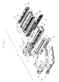
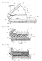
- FIG. 1 is an exploded perspective view illustrative of a lever-type connector according to an aspect of the present invention.
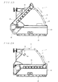
- FIG. 2A and FIG. 2B illustrate the lever-type connector of FIG. 1
- FIG. 2A illustrates a lever at a separated position
- FIG. 2B illustrates the lever at a mating position.
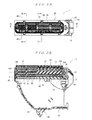
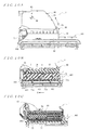
- FIG. 3A and FIG. 3B illustrate the lever-type connector of FIG. 1
- FIG. 3A is a front view thereof
- FIG. 3B is a cross-sectional view thereof taken along line 3B-3B of FIG. 3A .
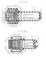
- FIG. 4A and FIG. 4B illustrate the lever-type connector of FIG. 1
- FIG. 4A is a cross-sectional view thereof taken along line 4A-4A of FIG. 3A
- FIG. 4B is a cross-sectional view thereof taken along line 4B-4B of FIG. 3A
- FIG. 5 is a cross-sectional view taken along line 5-5 of FIG. 4 . Additionally, in FIG. 5 , the state where a retainer at a permanent locking position is illustrated.
- FIG. 6A and FIG. 6B illustrate the lever-type connector with a lever located at a separated position
- FIG. 6A is a cross-sectional view illustrative of the lever and a slider
- FIG. 6B is a cross-sectional view thereof taken along line 6B-6B of FIG. 6A .
- a lever-type connector 1 illustrated in FIG. 1 includes: an inner housing 10; a front cover 20; a retainer 30; a first sealing member 40; a second sealing member (family sealing member) 50; an outer housing 60; a pair of sliders 70; a lever 80; an a wire cover 90.
- the inner housing 10 is integrally formed by molding an insulating resin.
- the inner housing 10 is provided with: a housing main body 11 that has a substantially rectangular parallelepiped shape and that extends in the widthwise direction (left-and-right direction in FIG. 3A ), in the up-and-down direction (up-and-down direction in FIG.
- the housing main body 11 is provided with multiple contact accommodating cavities 13 that extend therethrough in the front-and-rear direction.
- the inner space of the hood portion 12 defines a second sealing member accommodating space 14.
- Each of the contact accommodating cavities 13 is provided with a housing lance 15 that primarily latches a contact, not illustrated.
- the housingmainbody 11 is provided with a retainer accommodating depression 17 that opens downward and extends upward, as illustrated in FIG. 4B .
- the upper surface of the retainer accommodating depression 17 is provided with multiple openings 17a, as illustrated in FIG. 1 and FIG. 4B .
- Front cover retaining protrusions 32, to be described later, of the retainer 30 are allowed to penetrate through the openings 17a, respectively, to project at the upper side of the housing main body 11.
- a pair of larch arms 16, which latch the outer housing 60 with the inner housing 10 are formed to protrude rearward at both end portions in the widthwise direction of the hood portion 12 of the inner housing 10, as illustrated in FIG. 1 .
- the front surface of the housing main body 11 of the inner housing 10 is provided with multiple grooves 18e that penetrate therethrough in the up-and-down direction, as illustrated in FIG. 4A .
- the front end portion of each of the grooves 18e is provided with a pair of latching portions 18a that are latched with elastic latch arms, spaced away from each other at given intervals in the up-and-down direction, arranged at the front cover 20, respectively, as illustrated in FIG. 4A .
- Each of the latching portions 18a is provided to come across the groove 18e in the widthwise direction.
- the bottom surface of the housing main body 11, that is, the front surface of the retainer accommodating depression 17 in the housing main body 11, is provided with multiple cutouts 18b that are latched with elastic latch arms 26b arranged at the front cover 20, as illustrated in FIG. 4B .
- the top surface of the housing main body 11 is provided with a depression portion 18c into which a projection 26c arranged at the front cover 20 enters, as illustrated in FIG. 4A .
- both of side walls in the widthwise direction of the housing main body 11 are provided with latching depression portions 18d to be locked with elastic side locks 26d arranged at the front cover 20, respectively, as illustrated in FIG. 3B .
- multiple projections 19 are formed to protrude at given intervals in the widthwise direction at both of upper and lower surfaces of the hoodportion 12 of the inner housing 10.
- the front cover 20 is attached to the front side of the inner housing 10, and is provided with a cover main body 21 that extends in the widthwise direction so as to cover the front surface of the housing main body 11, as illustrated in FIG. 1 .
- the front cover 20 is formed by molding an insulating resin.
- a hood portion 22 that covers the upper surface and both of side surfaces in the widthwise direction is provided at the rear surface of the cover main body 21 so as to extend rearward.
- multiple contact accommodating chambers 23 are defined at the rear surface of the cover main body 21 of the front cover 20, at positions corresponding to the contact accommodating cavities 13 provided at the housing main body 11, as illustrated in FIG. 4B and FIG. 5 .
- multiple mating terminal insertion openings 24 communicated with the contact accommodating chambers 23 at the front surface of the cover main body 21, at positions corresponding to the contact accommodating cavities 13 provided at the housing main body 11.
- tool openings 25 into which a tool (not illustrated) for removing the contacts (not illustrated) by operating the housing lance 15 are defined at the front surface of the cover main body 21 and below the mating terminal insertion openings 24.
- the provision of the front cover 20 avoids the drawbacks that a mating terminal (not illustrated) arranged at a mating connector 401 is brought into contact with a contact and the like, when the lever-type connector 1 is mated with the mating connector 401 (see FIG. 7A to FIG. 7C ). That is to say, it is possible to protect the contacts accommodated in the inner housing 10. Also, multiple pairs of elastic latch arms 26a are formed at the cover main body 21 of the front cover 20 so as to protrude rearward at given intervals in the widthwise direction, as illustrated in FIG. 1 . Each of the elastic latch arms 2 6a is pushed between the pair of the latching portions 18a arranged at the inner housing 10 so as to be latched with the latching portions 18a, as illustrated in FIG. 4A .
- Each pair of the elastic latch arms 2 6a are arranged, as illustrated in FIG. 4A , to be spaced apart from each other at given intervals in the up-and-down direction of the cover main body 21.
- multiple elastic latch arms 26b to be respectively latched with the cutouts 18b arranged at the inner housing 10 are provided below the cover main body 21 of the front cover 20, as illustrated in FIG. 4B .
- an upper wall 22a of the hood portion 22 in the front cover 20 is provided with the projection 26c that enters into a depression 28c arranged at the inner housing 10, as illustrated in FIG. 4A .
- both of the side walls of the hood portion 22 in the front cover 20 are provided with a pair of the elastic side locks 26d to be locked with the latching depression portions 18d of the inner housing 10.
- the upper wall 22a of the hood portion 22 in the front cover 20 is provided with multiple openings 27 through which the front cover retaining protrusions 32, to be described later, of the retainer 30 are inserted, as illustrated in FIG. 4B .
- Each of the openings 27 regulates the movement in the front-and-rear direction of the front cover 20 with each of the front cover retaining protrusions 32 of the retainer 30 inserted into each of the openings 27, when the retainer 30 is attached to the inner housing 10.
- the retainer 30 is attached in the retainer accommodating depression 17 from the lower side of the inner housing 10.
- the retainer 30 is formed to have a substantially plate shape that extends in the widthwise direction.
- the retainer 30 is temporarily retained by the inner housing 10 at a temporary lockingposition illustrated in FIG. 4A and FIG. 4B , is further pushed into the inner housing 10, and is secured by the inner housing 10 at a proper locking position illustrated in FIG. 5 .
- the proper locking state of the retainer 30 denotes that the retainer 30 is pushed completely.
- the retainer 30 has multiple contact insertion openings 31 arranged to correspond to the contact accommodating cavities 13, respectively, arranged at the housing main body 11, as illustrated in FIG. 4B .
- multiple front cover retaining protrusions 32 are formed to protrude upward at an upper end surface 30a of the retainer 30.
- the first sealing member 40 is formed to have a ring shape to be in tight contact with the outside of the housing main body 11 of the inner housing 10, as illustrated in FIG. 1 , FIG. 4A, and FIG. 4B .
- the first sealing member 40 seals between the housing main body 11 and the mating connector 401, and has a function of preventing water entering into the inner housing 10 from the mating part, when the lever-type connector 1 is mated with the mating connector 401.
- the second sealing member 50 is what is called a family sealingmember.
- the second sealingmember 50 is formed to have a substantially plate shape and is accommodated in a second sealing member accommodating space 14 of the hood portion 12 in the inner housing 10 so as to be in tight contact with the inner circumferential surface of the hood portion 12, as illustrated in FIG. 1 and FIG. 4A .
- the second sealing member 50 is provided with multiple electrical wire insertion openings 51 at positions corresponding to the contact accommodating cavities 13, respectively, as illustrated in FIG. 1 and FIG. 4B .
- the electrical wires (not illustrated) connected to the contacts accommodated in the contact accommodating cavities 13 are extracted rearward through the electrical wire insertion openings 51.
- the outer housing 60 is attached to the rear side of the inner housing 10 to prevent the separation of the second sealingmember 50.
- the outer housing 60 is formed to be a single member by molding an insulating resin.
- the outer housing 60 is formed to have a substantially rectangular parallelepiped shape that extends in the widthwise direction, in the front-and-rear direction, and in the up-and-down direction.
- the outer housing 60 is provided with: a main body 61 that extends in the widthwise direction and that is located at the rear side of the second sealing member 50; and a hood portion 62 that extends frontward from an outer circumferential end portion of the main body 61 and that covers the inner housing 10, as illustrated in FIG. 4A .
- the main body 61 of the outer housing 60 is provided with multiple electrical wire extracting openings 63 at positions corresponding to the contact accommodating cavities 13, respectively, as illustrated in FIG. 4B .
- a pair of slider accommodating slots 64 that extend in the widthwise direction are defined at both of upper and lower portions of the hood portion 62 of the outer housing 60.
- a step portion 66, with which the latch arm 16 arranged at the inner housing 10 is latched, is provided at the rear surface of the outer housing 60, as illustrated in FIG. 3B .
- a pivot receiving portion 65 into which a pivot 84, to be described later, of the lever 80 is fit is provided at one end portion in the widthwise direction of the hood portion 62 of the outer housing 60, as illustrated in FIG. 1 .
- Each slider 70 is formed to have a substantially plate shape by molding an insulating resin, and is movably accommodated in the slider accommodating slot 64 of the outer housing 60.
- the inner surface of each of the sliders 70 is provided with cam grooves 71 into which cam pins 411 (see FIG. 7A to FIG. 7C ) arranged at the mating connector 401 enter, respectively.
- one end portion of the inner surface of each of the sliders 70 is provided with a depression portion 72 into which a projection for slider movement 85, to be described later, arranged at the lever 80 is inserted.
- the inner surface of each slider 70 is provided with a projection insertion groove 73 into which the projections 19 arranged at the inner housing 10 are respectively fit, as illustrated in FIG. 1 and FIG. 4A to FIG.
- the projection insertion groove 73 linearly extends from an end edge opposite to the end portion having the depression portion 72 in the slider 70, and the width of the projection insertion groove 73 is made slightly wider than the diameter of the projection 19.
- the projection insertion groove 73 pulls the inner housing 10 in the direction of arrow Y via the projections 19 as illustrated in FIG. 5 , when the lever-type connector 1 is separated from the mating connector 401, as will be described later in more detail.
- the lever 80 is provided with: a pair of arm portions 81; and a connecting portion 82 that connects one ends of the arm portions 81, as illustrated in FIG. 1 .
- the other end of each of the arm portions 81 is provided with an extension portion 83 that extends at right angle with respect to the arm portion 81, and the inner surface of an end of each extension portion 83 is provided with the spindle 84 to be formed to protrude.
- the outer surface of the other end portion of each arm portion 81 is provided with the projection for slider movement 85 that is fit into the depression portion 72 of each slider 70.
- the pivot 84 of the lever 80 is fit into the pivot receiving portion 65 arranged at one end in the widthwise direction of the outer housing 60, so as to rotate in both of the direction of arrow A illustrated in FIG. 2A and the direction of arrow B illustrated in FIG. 2B , with respect to the outer housing 60.
- the projection for slider movement 85 arranged at the lever 80 pushes the slider 70. This causes the slider 70 to interlock with the lever 80 and slide in the direction of being accommodated in the slider accommodating slot 64.
- the operation of the cam grooves 71 and the cam pins 411 causes the lever-type connector 1 and the mating connector 401 to come closer to each other and come to the mating state. Conversely, when the lever 80 is rotated from the mating position to the separated position in the direction of arrow B, the slider 70 interlocks with the lever 80 to slide in the direction of getting out of the slider accommodating slot 64. The operation of the cam grooves 71 and the cam pins 411 causes the lever-type connector 1 and the mating connector 401 to be separated from each other. Such mating and separating operations will be described later in more detail.
- the wire cover 90 includes: a lower side cover member 91; and an upper side cover member 92 that is attached at the lower side cover member 91.
- the wire cover 90 is attached at the rear side of the outer housing 60 so as to extract multiple electrical wires extracted from the electrical wire extracting openings 61 of the outer housing 60 to one side in the widthwise direction of the outer housing 60.
- Each of the upper side cover member 91 and the lower side cover member 92 is provided with a first regulating projection 94 that regulates the rotation in the direction of arrow A from the separated position of the lever 80, as illustrated in FIG. 1 , FIG. 2A , FIG. 2B , FIG. 6A, and FIG. 6B .
- each of the upper side cover member 91 and the lower side cover member 92 is provided with a second regulating projection 95 that regulates the rotation in the direction opposite to the direction of arrow A from the separated position of the lever 80, as illustrated in FIG. 1 , FIG. 2A , FIG. 2B , FIG. 6A, and FIG. 6B .
- the lower side cover member 92 is provided with a lock member 93 that prevents the rotation in the direction of arrow B, when the lever 80 rotates in the direction of arrow A and is located at the mating position.
- the first sealing member 40 is firstly attached to the outside of the housing main body 11 in the inner housing 10.
- the front cover 20 is attached to the front side of the inner housing 10.
- each pair of the elastic latch arms 26a are pushed between each pair of the latching portions 18a arranged at the inner housing 10 and are latched by the latching portions 18a.
- the projection 26c arranged at the front cover 20 enters into the depression portion 18c arranged at the inner housing 10. Also, as illustrated in FIG.
- the elastic latch arms 26b arranged at the front cover 20 are latched by the cutouts 18b arranged at the inner housing 10. Further, as illustrated in FIG. 3B , the elastic side locks 26d arranged at the front cover 20 are latched by the latching depression portions 18d of the inner housing 10.
- the retainer 30 is inserted into the retainer accommodating depression 17 from the lower side of the inner housing 10, and is locked at the temporary position, as illustrated in FIG. 4A and FIG. 4B .
- each of the contact insertion openings 31 is located at the position conforming to the corresponding contact accommodating cavity 13 of the inner housing 10.
- the front cover retaining protrusion 32 of the retainer 30 protrudes through the opening 17a of the inner housing 10 and penetrates through the opening 27 of the front cover 20, as illustrated in FIG. 4B , thereby regulating the movement in the front-and-rear direction of the front cover 20.
- the second sealingmember 50 is accommodated in the second sealing member accommodating space 14 of the hood portion 12 from the rear side of the inner housing 10. This causes the outer circumferential surface of the second sealing member 50 to be tight with the inner circumferential surface of the hood portion 12.
- the outer housing 60 is attached from the rear side of the inner housing 10 to which the first sealing member 40, the front cover 20, the retainer 30, and the second sealing member 50 are installed.
- a latch arm 16 arranged at the inner housing 10 is latched with the step portion 66 of the outer housing 60. This prevents the separation of the second sealing member 50 from the second sealing member accommodating space 14.
- the pair of the sliders 70 are inserted into the slider accommodating slots 64 of the outer housing 60 from the end edge of the side opposite to the depression portion 72 arranged at one end thereof.
- the projections 19 arranged at the inner housing 10 are fit into the projection insertion groove 73 of the slider 70.
- the pivot 84 of the lever 80 is fit into the pivot receiving portion 65 arranged at one end portion in the widthwise direction of the outer housing 60, and the projection for slider movement 85 of the lever 80 is fit into the depression portion 72 of each slider 70.
- the lever 80 is rotatable in both of the direction of arrow A illustrated in FIG. 2A and the direction of arrow B illustrated in FIG. 2B .
- the sliders 70 are capable of moving slidably in the slider accommodating slot 64 in conjunction with the rotational movement of the lever 80.
- the housing lance 15 arranged at the inner housing 10 primarily locks each contact.
- the retainer 30 at the temporary locking position is pushed to the proper locking position. Then, the contacts are locked by the retainer 30 secondarily.
- the front cover retaining protrusions 32 arranged at the retainer pass through the openings 27 of the front cover 20 and regulates the movement of the front cover 20 in the front-and-rear direction.
- the wire cover 90 is attached at the rear side of the outer housing 60, and then multiple electrical wires extracted from the electrical wire extracting openings 63 of the outer housing 60 to be further extracted to one side in the longitudinal direction of the outer housing 60. The assembling of the lever-type connector 1 is completed by the above processing.
- FIG. 7A to FIG. 7C are explanatory views illustrative of a state before the lever-type connector and the mating connector are mated.
- FIG. 8A to FIG. 8C are explanatory views illustrative of a mating state where the lever-type connector and the mating connector are mated.
- FIG. 9A to FIG. 9C are explanatory views illustrative of a state where the lever-type connector and the mating connector are on the way of being mated.
- FIG. 10A to FIG. 10C are explanatory views illustrative of a state where the mating of the lever-type connector and the mating connector is completed.
- the lever 80 and the slider 70 are firstly located at separated positions illustrated in FIG. 7A to FIG. 7C .
- the rotation of the lever 80 in the direction of arrow A illustrated in FIG. 8A to FIG. 8C is regulated by the first regulating projection 94 arranged at the lower side cover member 91 and the upper side cover member 92.
- the mating connector 401 is pushed in the direction of arrow C from the front side of the lever-type connector 1 as illustrated in FIG. 7A to FIG. 7C .
- the cam pins 411 arranged at the housing 410 in the mating connector 401 enter inlets 71a of the cam grooves 71 arranged at the sliders 70, respectively, leading to the temporary mating state where the lever-type connector 1 and the mating connector 401 are mated with each other, as illustrated in FIG. 8A to FIG. 8C .
- the front end surface of the slider 70 firstlypushes a front surface 64a of the slider accommodating slot 64 arranged at the outer housing 60 in the direction of arrow X, as illustrated in FIG. 5 , that is, the direction of getting closer to the mating connector 401.
- the outer housing 60 pushes a rear end surface 12a of the inner housing 10 in the direction of getting closer to the mating connector 401.
- the lock member 93 is firstly pushed so that the lever 80 can rotate.
- the lever 80 at the mating position is rotated in the direction of arrow B as illustrated in FIG. 10A to FIG. 10C to be located at the separated position.
- the projection for slider movement 85 arranged at the lever 80 pushes the slider 70 in the direction of arrow E as illustrated in FIG. 10 , making the sliders slide in conjunction with the lever 80.
- the lever-type connector 1 and the mating connector 401 come through the state where the lever-type connector 1 and the mating connector 401 are on the way of being mated, and reach to the temporary mating state as illustrated in FIG. 8A to FIG. 8C .
- the operation of the cam grooves 71 arranged at the slider 70 and the cam pins 411 arranged at the mating connector 401 causes the lever-type connector 1 and the mating connector 401 to move in a direction of being separated from each other.
- the lever-type connector 1 is configured that the slider 70 pulls the inner housing 10 to get away from the mating connector 401, when being separated from the mating connector 401. Even if a great mating force between the inner housing 10 and the mating connector 401 is exerted, it is possible to prevent the separation of the inner housing 10 from the outer housing 60 to remain at the mating connector 401 side. The retaining force of the outer housing 60 and the inner housing 10 is not related to the separation of the lever-type connector 1 from the mating connector 401.
- the lever-type connector 1 is configured such that the projection insertion groove 73 of the slider 70 pulls the inner housing 10 via the projections 19, when being separated from the mating connector 401. Accordingly, the sliders 70 are capable of pulling the inner housing 10 with a simple configuration.
- the front end surface of the slider 70 firstly pushes the front surface 64a of the slider accommodating slot 64 arranged at the outer housing 60 in a direction of getting closer to the mating connector 401.
- the outer housing 60 pushes the rear end surface 12a of the inner housing 10 in a direction of getting closer to the mating connector 401. It is therefore possible to avoid the projection insertion groove 73 of the slider 70 from directly pushing the projections 19 of the inner housing 10 in a direction of getting closer to the mating connector 401, when the lever-type connector 1 and the mating connector 401 are mated with each other.
- the projection insertion groove 73 of the slider 70 directly pushes the projections 19 of the inner housing 10 in the direction of getting closer to the mating connector 401, a greater mating force will be needed between the inner housing 10 and the mating connector 401 as the number of the terminals is increased. Accordingly, a great force will be exerted onto the projection insertion groove 73 of the slider 70 by the projections 19. If such a great force is exerted onto the projection insertion groove 73 by the projections 19, the projection insertion groove 73 may be broken.
- the lever-type connector 1 when the mating of the lever-type connector 1 and the mating connector 401 is separated from each other, the lever-type connector 1 is configured such that the projection insertion groove 73 of the slider 70 pulls the inner housing 10 via the projections 19.
- the present invention is not limited to the above configuration, as long as the slider 70 pulls the inner housing 10.
- a projection may be provided at the slider 70 and a projection fitting groove may be provided at the inner housing 10.
Landscapes
- Details Of Connecting Devices For Male And Female Coupling (AREA)
- Connector Housings Or Holding Contact Members (AREA)
Abstract
Description
- The present invention relates to what is called lever-type connectors to reduce an operational force for mating.
- When connectors with lots of terminals are mated, the mating resistance generated between mating contacts in both of the connectors is made greater. Hence, it is difficult to mate the connectors by pushing the connectors by hand. For this reason, several kinds of what is called lever-type connectors that utilize a toggle for reducing the operational force for mating have been proposed. As a conventional lever-type connector of such a kind, for example, the connectors shown in
FIG. 11 and FIG. 12 are known (see Patent Document 1).FIG. 11 is a cross-sectional view of a conventional lever-type connector.FIG. 12 is a cross-sectional view of a housing for use in the lever-type connector shown inFIG. 11 . A lever-type connector 101 shown inFIG. 11 is configured to be mated with amating connector 150, and includes ahousing 110, a pair ofsliders 120, alever 130, and awire cover 140. - The
housing 110 has, as shown inFIG. 12 , acontact accommodating portion 112 having multiplecontact accommodating cavities 111 that extend in the front-and-rear direction (inFIG. 12 , the left side denotes front side and the right side denotes rear side). Each of thecontact accommodating cavities 111 accommodates a metal contact (not shown) connected to an electrical wire (not shown). In addition, thehousing 110 is provided with a pair of upper and lower (inFIG. 12 , the upper side denotes upper side and the lower side denotes lower side)slider accommodating slots 113 that open at both of its left and right end surfaces (inFIG. 11 , the left side denotes left side and the right side denotes right side). Furthermore, a pair of upper and lowerlever accommodating grooves 114 that open at the rear surface of thehousing 110 are defined in thehousing 110 and at the upper and lower outsides of the slider accommodatingslot 113. A sealingmember 115 is provided at the outer circumference of thecontact accommodating portion 112. The sealingmember 115 seals between themating connector 150 to be mated with and thecontact accommodating portion 112 so as to have a function of preventing water from entering into thecontact accommodating cavities 111 from the mating part side. - Each of the
sliders 120 is formed to have a plate shape, and is movably accommodated in the slider accommodatingslot 113 of thehousing 110. The inner surface of eachslider 120 is provided withcam grooves 121 into whichcam pins 152 arranged at amating part 151 of themating connector 150 are inserted, as shown inFIG. 11 . Also, the outer surface of eachslider 120 is provided with apin portion 122 that is inserted into an interlockinggroove 133, to be described later, arranged at thelever 130. - Additionally, the
lever 130 is provided to extend from a pair of arm portions 132 (only one of the arm portions is shown inFIG. 11 ), each having a plate shape from both ends of anoperation portion 131. Eacharm portion 132 is provided with a pin opening 134. Thelever 130 is supported for rotation with respect to thewire cover 140 by making the pin opening 134 fit with a supportingpin 141 arranged at thewire cover 140. Also, eacharm portion 132 is provided with the interlockinggroove 133 from its outer circumferential edge toward the pin opening 134. Further, thewire cover 140 is attached at the rear side of thehousing 110, so as to extract the electrical wire extracted from thehousing 110 at one side of the left-and-right direction of thehousing 110. - In order to mate the lever-
type connector 101 and themating connector 150, thelever 130 and thesliders 120 are firstly located at separated positions, so that themating part 151 of themating connector 150 is mated from the front side of the lever-type connector 101. Then, thecam pins 152 of themating connector 150 enter the inlets of thecam grooves 121 arranged at theslider 120, as shown inFIG. 11 , so bothconnectors lever 130 at a separated position is rotated toward the mating position, the interlockinggroove 133 arranged at thelever 130 pushes thepin portion 122 of theslider 120 to the mating position. Thus, theslider 120 interlocks with thelever 130 to move from the separated position to the mating position. The operation of thecam grooves 121 and thecam pins 152 causes both of theconnectors lever 130 at the mating position is rotated toward the separated position, theslider 120 interlocks with thelever 130 to move from the mating position to the separated position. The operation of thecam grooves 121 and thecam pins 152 causes both of theconnectors - In this manner, the lever-
type connector 101 is configured to employ the toggle including: thelever 130 that rotates; and theslider 120 that interlocks with thelever 130 and that has thecam grooves 121. Thus, the operational force for mating can be reduced considerably. In the lever-type connector 101 shown inFIG. 11 and FIG. 12 , themating connector 150 to be mated with and thecontact accommodating portion 112 are sealed with the sealingmember 115 arranged at the outer circumference of thecontact accommodating portion 112, thereby preventing water from entering into thecontact accommodating cavities 111 from the mating side (front side) to be mated with the mating connector. In the lever-type connector 101, however, it is impossible to prevent water from entering into thecontact accommodating cavities 111 from the opposite side to the side to be mated with the mating connector. - Hence, conventionally, there is known a connector shown in
FIG. 13 and FIG. 14 , for example, as a connector that utilizes a cam-type toggle for preventing water from entering from the opposite side to the side to be mated with the mating connector (see Patent Document 2).FIG. 13 is a plan view of a connector that utilizes the conventional cam-type toggle.
FIG. 14 is a cross-sectional view of the connector ofFIG. 13 . Aconnector 201 that utilizes the cam-type toggle shown inFIG. 13 and FIG. 14 is configured to be mated with amating connector 250, and is provided with ahousing 210 and a pair of slide-type levers 220. - The
housing 210 includes, as shown inFIG. 14 , acontact accommodating portion 212 having multiplecontact accommodating cavities 211 that extend in the front-and-rear direction (inFIG. 14 , the left side denotes front side and the right side denotes rear side). Each of thecontact accommodating cavities 211 accommodates ametal contact 214 connected to an electrical wire (not shown). In addition, thehousing 210 includes a pair of upper and lower (inFIG. 14 , the upper side denotes upper side and the lower side denotes lower side)lever accommodating grooves 213 that open at both of its left and right end surfaces (inFIG. 13 , the left side denotes left side and the right side denotes right side). Afirst sealing member 215 is provided at the outer circumference of thecontact accommodating portion 212. Thefirst sealing member 215 seals between amating part 251 of themating connector 250 to be mated with and thecontact accommodating portion 212 to have a function of preventing water from entering into thecontact accommodating cavities 211 from the mating part side. Additionally, a second sealingmember accommodating depression 216 is provided at the rear surface of thehousing 210. - The second sealing
member accommodating depression 216 accommodates a second sealingmember 240 having multiple electricalwire extracting openings 231 arranged at the positions corresponding to thecontact accommodating cavities 211, respectively. Thesecond sealing member 240 is what is called a collective-type sealing member, such that the electricalwire extracting openings 231 are in tight contact with the outer circumferential surfaces of electrical wires connected tocontacts 214, and in addition, the outer circumferential surface of thesecond sealing member 230 is in tight contact with the inner circumferential surface of thesecond sealing member 216. This prevents water from entering into thecontact accommodating cavities 211 from the opposite side (rear side) to the side to be mated with themating connector 150. A pushingmember 230 for preventing the separation of thesecond sealing member 240 is attached at the rear side of thesecond sealing member 240. Alatching arm 217 arranged at thehousing 210 elastically latches alatching portion 232 arranged at the pushingmember 230, whereby the pushingmember 230 is attached to thehousing 210. - Each of the
levers 220 is formed to have a plate shape, and is movably accommodated in thelever accommodating groove 213 of thehousing 210. The inner surface of eachlever 220 is provided with acam groove 221 into which acam pin 252 arranged at amating part 251 of themating connector 250 is inserted, as shown inFIG. 13 . In order to mate theconnector 201 and themating connector 250, thelever 220 is firstly located at a separated position, so that themating part 251 of themating connector 250 is mated from the front side of the lever-type connector 201. Then, thecam pin 252 of themating connector 250 enters the inlet of thecam groove 221 arranged at thelever 220, as shown inFIG. 13 , so bothconnectors lever 220 at the separated position is pushed to the mating position, the operation of thecam groove 221 and thecam pin 252 causes both of theconnectors lever 220 at the mating position is returned to the separated position, the operation of thecam groove 221 and thecam pin 252 causes both of theconnectors - In the
connector 201 that utilizes the cam-type toggle , thefirst sealing member 215 is capable of sealing between thecontact accommodating portion 212 and themating connector 250 to be mated with, and in addition, thefirst sealing member 215 is capable of preventing water from entering into thecontact accommodating cavities 211 from the opposite side to the side to be mated with the mating connector. Also, the provision of the toggle including thelever 220, of a slide type, having thecam groove 221 achieves the reduction in the operational force for mating. - It should be noted, however, that the
connector 201 is configured such that thelever 220 of a slide type is directly operated by hand. Accordingly, the reduction in the operational force for mating cannot be expected too much, as compared to the lever-type connector 101 having a toggle including thelever 130 that rotates and theslider 120 that interlocks with thelever 130 and that has thecam grooves 121. Hence, conventionally, as schematically shown inFIG. 15 , there has been developed a lever-type connector in which a family sealing member is provided for preventing water from entering into the contact accommodating cavities from the opposite side to the side to be mated with the mating connector. In addition, such a lever-type connector has a toggle including: a lever that rotates; and a slider that interlocks with the lever and that has cam grooves.FIG. 15 schematically shows a cross-sectional view of another conventional lever-type connector. - A lever-
type connector 301 shown inFiG.15 is configured to be mated with a mating connector C, and is provided with aninner housing 310, asealingmember 320,afamilysealing member 330, anouter housing 340, a pair ofsliders 350, alever 360, and awire cover 370. Theinner housing 310 includes: a housingmain body 312 having multiplecontact accommodating cavities 311 that extend in the front-and-rear direction (inFIG. 15 , the left side denotes front side and the right side denotes rear side); and ahood portion 313 that protrudes rearward from the housingmain body 312. Each of thecontact accommodating cavities 311 accommodates a metal contact (not shown) connected to an electrical wire (not shown). The sealingmember 320 is arranged at the outer periphery of the housingmain body 312, so as to seal between the housingmain body 312 and the mating connector to be mated with, thereby preventing water entering into thecontact accommodating cavities 311. - In addition, the
family sealing member 330 is accommodated in thehood portion 313 of theinner housing 310 so as to be in tight contact with the inner circumferential surface of thehood portion 313. Thefamily sealing member 330 prevents water from entering into thecontact accommodating cavities 311 from the rear side of theinner housing 310. Anouter housing 340 is attached to the rear side of thefamily sealing member 330 so as to prevent the separation of thefamily sealing member 330. A latching arm (not shown) arranged at theinner housing 310 elastically latches a latching portion (not shown) arranged at theouter housing 340, whereby theouter housing 340 is attached to theinner housing 310. - The
outer housing 340 is provided with: amain body 341 located at the rear side of thefamily sealing member 330; and ahood portion 342 that extends frontward from the outer circumferential end portion of themain body 341 so as to cover theinner housing 310. Apair ofslider accommodating slots 343 that extend in the left-and-right direction (in a direction orthogonal to the sheet surface ofFIG. 15 ) are provided at both of upper and lower side portions of thehood portion 342 of theouter housing 340. - Each of the
sliders 350 is formed to have a substantially plate shape, and is movably accommodated in the slideraccommodating slot 343 of theouter housing 340. The inner surface of eachslider 350 is provided with acam groove 351 into which a cam pin (not shown) arranged at the mating connector is inserted. Also, eachslider 350 is provided with a groove (not shown) into which a pin for slider movement arranged (not shown) at thelever 360. - Additionally, the
lever 360 is rotatably supported with respect to theouter housing 340 so that the rotation of thelever 360 causes thesliders 350 to slide in the left-and-right direction. Further, thewire cover 370 is attached to the rear side of theouter housing 340, so as to extract the electrical wire extracted from theouter housing 340 at one side in the left-and-right direction of theouter housing 340. - In order to mate the above lever-
type connector 301 and the mating connector C, thelever 360 and thesliders 350 are firstly located at separated positions, so that the mating connector C is mated from the front side of the lever-type connector 301. Then, the cam pin of the mating connector C enters the inlet of thecam groove 351 arranged at theslider 350, so both of the lever-type connector 301 and the mating connector C come to a temporary mating state. Subsequently, when thelever 360 at the separated position is rotated toward the mating position, the pin for slider movement arranged at thelever 360 pushes thesliders 350. Thus, theslider 350 interlocks with thelever 360 to slide from the separated position to the mating position. The operation of thecam groove 351 and the cam pin causes both of the lever-type connector 301 and the mating connector C to come closer to each other and come to the mating state. Conversely, when thelever 360 at the mating position is rotated toward the separated position, theslider 350 interlocks with thelever 360 to slide from the mating position to the separatedposition. The operation of thecam groove 351 and the cam pin causes the lever-type connector 301 and the mating connector C to be separated from each other. - In this manner, the lever-
type connector 301 is provided with thefamily sealing member 330 to prevent water from entering into thecontact accommodating cavities 311 from the rear side of theinner housing 310. Also, the lever-type connector 301 employs the toggle including: thelever 360 that rotates; and theslider 350 that interlocks with thelever 360 and that has acam groove 351, thereby significantly reducing the operational force for mating. Additionally, theslider 350 is configured to be accommodated in theouter housing 340 for preventing the separation of thefamily sealing member 330, thereby downsizing the lever-type connector 301 and making the connector structure simple. - Patent Document 1:
JP 2003-132996 A - Patent Document 2:
JP 2003-331983 A - The lever-
type connector 301 shown inFIG. 15 , however, has following drawbacks. That is, in order to mate the lever-type connector 301 and the mating connector C, when thelever 360 at the separated position is rotated toward the mating position, theslider 350 interlocks with thelever 360 and slides from the separated position to the mating position in the slideraccommodating slot 343 in the left-and-right direction. The operation of thecam groove 351 and cam pin causes the lever-type connector 301 and the mating connector C to come closer and come to a mating state. In this process, the front end surface of theslider 350 firstly pushes afront surface 343b of the slideraccommodating slot 343 arranged at theouter housing 340 in a direction of arrow X, that is, in the direction of getting closer to the mating connector C. Next, theouter housing 340 pushes therear end surface 313a of theinner housing 310 in the direction of arrow X. - Meanwhile, in order to separate the lever-
type connector 301 and the mating connector C from each other, when thelever 360 at the mating position is rotated toward the separated position, theslider 350 interlocks with thelever 360 and slides from the mating position to the separated position in the slideraccommodating slot 343 in the left-and-right direction. The operation of thecam groove 351 and cam pin causes the lever-type connector 301 and the mating connector C to be separated from each other. In this process, the rear end surface of theslider 350 firstly pushes arear surface 343a of the slideraccommodating slot 343 arranged at theouter housing 340 in a direction of arrow Y, that is, in the direction of getting away from the mating connector C. Next, theouter housing 340 pushes theinner housing 310 in the direction of arrow Y via the latching portion, and the latching arm of theinner housing 310. - In this manner, when the lever-
type connector 301 and the mating connector C are separated from each other, theouter housing 340 pulls theinner housing 310 in the direction of arrow Y via the latching portion, and the latching arm of theinner housing 310. In such a structure, connectors with lots of terminals are mated with each other and the mating resistance generated between both contacts becomes greater. Since the mating force of theinner housing 310 and the mating connector C is great, a great force is exerted onto the latching portion of theouter housing 340 and the latching arm of theinner housing 310. This damages the latching portion and the latching arm and causes malfunction in some cases. In a case where the latching portion does not function normally as described, theouter housing 340 cannot pull theinner housing 310 sufficiently and theinner housing 310 is separated from theouter housing 340, remaining at the mating connector C side. - Meanwhile, if the structure is configured such that the retaining force of the
outer housing 340 and theinner housing 310 is enhanced by the latching portion of theouter housing 340 and the latching arm of theinner housing 310 so that theouter housing 340 can pull theinner housing 310 with certainty, there are limitations in the need for downsizing the lever-type connectors. Therefore, the present invention has been made in view of the above circumstances, and has an object of providing a lever-type connector in which sliders are accommodated in slider accommodating slots of an outer housing, respectively, thereby preventing the separation of an inner housing from the outer housing and remaining at the mating connector side, when the lever-type connector and a mating connector are separated from each other. - In order to address the above drawbacks, the lever-type connector recited in claim 1, there is provided a lever-type connector comprising: an inner housing that accommodates a contact; an outer housing that is attached to the inner housing and that prevents separation of a family sealing member; a slider that is slidably accommodated in a slider accommodating slot provided at the outer housing and that has a cam groove into which a cam pin arranged at a mating connector is inserted; and a lever that is rotatably provided with respect to the outer housing and that makes the slider slide, wherein a rotational operation of the lever allows the lever-type connector to be mated with or separated from the mating connector, and wherein the slider pulls the inner housing in a direction of getting away from the mating connector, when the lever-type connector is separated from the mating connector.
- In addition, the lever-type connector, recited in claim 2, according to claim 1, wherein the inner housing is provided with a projection, the slider is provided with a projection insertion groove into which the projection is inserted, and the projection insertion groove pulls the inner housing via the projection when the lever-type connector is separated from the mating connector. Furthermore, the lever-type connector, recited in claim 3, according to claim 1, wherein when the lever-type connector is separated from the mating connector, the slider pulls the inner housing in a direction of getting away from the mating connector, and in addition, the inner housing pushes the outer housing in a direction of getting away from the mating connector in conjunction with the pulling operation of the inner housing.
- Moreover, the lever-type connector, recited in claim 4, according to claim 1, wherein when the lever-type connector is mated with the mating connector, the slider pushes the outer housing in a direction of getting closer to the mating connector, and in addition, the outer housing pushes the inner housing in a direction of getting closer to the mating connector in conjunction with the pushing operation of the outer housing.
- According to the lever-type connector recited in claim 1 of the present invention, when the lever-type connector is separated from the mating connector, the slider pulls the inner housing in the direction of getting away from the mating connector. Therefore, when the lever-type connector is separated from the mating connector, the slider directly pulls the inner housing in the direction of getting away from the mating connector and even if the mating force of the inner housing and the mating connector is made great, it is possible to prevent the dropping off from the inner housing from the outer housing so as not to remain at the mating connector side.
The retaining force of the outer housing and the inner housing is not related to the separation from the mating connector. - In addition, according to the lever-type connector recited in claim 2 of the present invention, in the lever-type connector of claim 1, the inner housing is provided with a projection, the slider is provided with a projection insertion groove into which the projection is inserted. When the lever-type connector is separated from the mating connector, the projection insertion groove pulls the inner housing via the projection, thereby making the slider directly pull the inner housing with a simple configuration.
- Furthermore, according to the lever-type connector recited in claim 3 of the present invention, in the lever-type connector of claim 1, when the lever-type connector is separated from the mating connector, the slider pulls the inner housing in a direction of getting away from the mating connector, and in addition, the inner housing pushes the outer housing in a direction of getting away from the mating connector in conjunction with the pulling operation of the inner housing. It is therefore possible to move the outer housing in a direction of getting away from the mating connector in conjunction with the pulling operation of the inner housing.
- Moreover, according to the lever-type connector recited in claim 4 of the present invention, in the lever-type connector of claim 1, when the lever-type connector is mated with the mating connector, the slider pushes the outer housing in a direction of getting closer to the mating connector, and in addition, the outer housing pushes the inner housing in a direction of getting closer to the mating connector in conjunction with the pushing operation of the outer housing. It is therefore possible to prevent the slider from making the inner housing directly pushing in the direction of getting closer to the mating connector, when the lever-type connector is mated with the mating connector.
-
-
FIG. 1 is an exploded perspective view illustrative of a lever-type connector according to an aspect of the present invention; -
FIG. 2A and FIG. 2B illustrate the lever-type connector ofFIG. 1 ,FIG. 2A illustrates a lever at a separated position, andFIG. 2B illustrates the lever at a mating position; -
FIG. 3A and FIG. 3B illustrate the lever-type connector ofFIG. 1 ,FIG. 3A is a front view thereof, andFIG. 3B is a cross-sectional view thereof taken alongline 3B-3B ofFIG. 3A ; -
FIG. 4A and FIG. 4B illustrate the lever-type connector ofFIG. 1 ,FIG. 4A is a cross-sectional view thereof taken alongline 4A-4A ofFIG. 3A , andFIG. 4B is a cross-sectional view thereof taken alongline 4B-4B ofFIG. 3A ; -
FIG. 5 is a cross-sectional view taken along line 5-5 ofFIG. 4 , and inFIG. 5 , the state where a retainer at a permanent locking position is illustrated; -
FIG. 6A and FIG. 6B illustrate the lever-type connector with a lever located at a separated position,FIG. 6A is a cross-sectional view illustrative of the lever and a slider, andFIG. 6B is a cross-sectional view thereof taken alongline 6B-6B ofFIG. 6A ; -
FIG. 7A to FIG. 7C are explanatory views illustrative of a state before the lever-type connector and the mating connector are mated; -
FIG. 8A to FIG. 8C are explanatory views illustrative of a mating state where the lever-type connector and the mating connector are mated; -
FIG. 9A to FIG. 9C are explanatory views illustrative of a state where the lever-type connector and the mating connector are on the way of being mated; -
FIG. 10A to FIG. 10C are explanatory views illustrative of a state where the mating of the lever-type connector and the mating connector is completed; -
FIG. 11 is a cross-sectional view of a conventional lever-type connector; -
FIG. 12 is a cross-sectional view of a housing for use in the lever-type connector shown inFIG. 11 ; -
FIG. 13 is a plan view of a connector that utilizes a conventional cam-type toggle; -
FIG. 14 is a cross-sectional view of the connector ofFIG. 13 ; and -
FIG. 15 schematically shows a cross-sectional view of another conventional lever-type connector. -
- 1
- lever-type connector
- 10
- inner housing
- 19
- projection
- 50
- second sealing member (family sealing member)
- 60
- outer housing
- 64
- slider accommodating slot
- 70
- slider
- 71
- cam groove
- 73
- projection insertion groove
- 80
- lever
- 401
- mating connector
- 411
- cam pin
- Embodiments of the present invention will now be described with reference to the drawings.
FIG. 1 is an exploded perspective view illustrative of a lever-type connector according to an aspect of the present invention.FIG. 2A and FIG. 2B illustrate the lever-type connector ofFIG. 1 ,FIG. 2A illustrates a lever at a separated position, andFIG. 2B illustrates the lever at a mating position.FIG. 3A and FIG. 3B illustrate the lever-type connector ofFIG. 1 ,FIG. 3A is a front view thereof, andFIG. 3B is a cross-sectional view thereof taken alongline 3B-3B ofFIG. 3A .FIG. 4A and FIG. 4B illustrate the lever-type connector ofFIG. 1 ,FIG. 4A is a cross-sectional view thereof taken alongline 4A-4A ofFIG. 3A , andFIG. 4B is a cross-sectional view thereof taken alongline 4B-4B ofFIG. 3A .FIG. 5 is a cross-sectional view taken along line 5-5 ofFIG. 4 . Additionally, inFIG. 5 , the state where a retainer at a permanent locking position is illustrated.FIG. 6A and FIG. 6B illustrate the lever-type connector with a lever located at a separated position,FIG. 6A is a cross-sectional view illustrative of the lever and a slider, andFIG. 6B is a cross-sectional view thereof taken alongline 6B-6B ofFIG. 6A . - A lever-type connector 1 illustrated in
FIG. 1 includes: aninner housing 10; afront cover 20; aretainer 30; a first sealingmember 40; a second sealing member (family sealing member) 50; anouter housing 60; a pair ofsliders 70; alever 80; an awire cover 90. Herein, theinner housing 10 is integrally formed by molding an insulating resin. As illustrated inFIG. 1 andFIG. 3A toFIG. 5 , theinner housing 10 is provided with: a housingmain body 11 that has a substantially rectangular parallelepiped shape and that extends in the widthwise direction (left-and-right direction inFIG. 3A ), in the up-and-down direction (up-and-down direction inFIG. 3A ), and in the front-and-rear direction (up-and-down direction inFIG. 3B ) ; and ahood portion 12 that extends rearward from the housingmain body 11. The housingmain body 11 is provided with multiplecontact accommodating cavities 13 that extend therethrough in the front-and-rear direction. The inner space of thehood portion 12 defines a second sealingmember accommodating space 14. Each of thecontact accommodating cavities 13 is provided with ahousing lance 15 that primarily latches a contact, not illustrated. - The
housingmainbody 11 is provided with aretainer accommodating depression 17 that opens downward and extends upward, as illustrated inFIG. 4B . The upper surface of theretainer accommodating depression 17 is provided withmultiple openings 17a, as illustrated inFIG. 1 andFIG. 4B . Frontcover retaining protrusions 32, to be described later, of theretainer 30 are allowed to penetrate through theopenings 17a, respectively, to project at the upper side of the housingmain body 11. - In addition, a pair of
larch arms 16, which latch theouter housing 60 with theinner housing 10, are formed to protrude rearward at both end portions in the widthwise direction of thehood portion 12 of theinner housing 10, as illustrated inFIG. 1 . Meanwhile, the front surface of the housingmain body 11 of theinner housing 10 is provided withmultiple grooves 18e that penetrate therethrough in the up-and-down direction, as illustrated inFIG. 4A . The front end portion of each of thegrooves 18e is provided with a pair of latchingportions 18a that are latched with elastic latch arms, spaced away from each other at given intervals in the up-and-down direction, arranged at thefront cover 20, respectively, as illustrated inFIG. 4A . Each of the latchingportions 18a is provided to come across thegroove 18e in the widthwise direction. Also, the bottom surface of the housingmain body 11, that is, the front surface of theretainer accommodating depression 17 in the housingmain body 11, is provided withmultiple cutouts 18b that are latched withelastic latch arms 26b arranged at thefront cover 20, as illustrated inFIG. 4B . - Further, the top surface of the housing
main body 11 is provided with adepression portion 18c into which aprojection 26c arranged at thefront cover 20 enters, as illustrated inFIG. 4A . Moreover, both of side walls in the widthwise direction of the housingmain body 11 are provided with latchingdepression portions 18d to be locked withelastic side locks 26d arranged at thefront cover 20, respectively, as illustrated inFIG. 3B . Also,multiple projections 19 are formed to protrude at given intervals in the widthwise direction at both of upper and lower surfaces of thehoodportion 12 of theinner housing 10. - Additionally, the
front cover 20 is attached to the front side of theinner housing 10, and is provided with a covermain body 21 that extends in the widthwise direction so as to cover the front surface of the housingmain body 11, as illustrated inFIG. 1 . Thefront cover 20 is formed by molding an insulating resin. Ahood portion 22 that covers the upper surface and both of side surfaces in the widthwise direction is provided at the rear surface of the covermain body 21 so as to extend rearward. - Herein, multiple
contact accommodating chambers 23 are defined at the rear surface of the covermain body 21 of thefront cover 20, at positions corresponding to thecontact accommodating cavities 13 provided at the housingmain body 11, as illustrated inFIG. 4B andFIG. 5 . In addition, multiple matingterminal insertion openings 24 communicated with thecontact accommodating chambers 23 at the front surface of the covermain body 21, at positions corresponding to thecontact accommodating cavities 13 provided at the housingmain body 11. Further,tool openings 25 into which a tool (not illustrated) for removing the contacts (not illustrated) by operating thehousing lance 15 are defined at the front surface of the covermain body 21 and below the matingterminal insertion openings 24. - The provision of the
front cover 20 avoids the drawbacks that a mating terminal (not illustrated) arranged at amating connector 401 is brought into contact with a contact and the like, when the lever-type connector 1 is mated with the mating connector 401 (seeFIG. 7A to FIG. 7C ). That is to say, it is possible to protect the contacts accommodated in theinner housing 10. Also, multiple pairs ofelastic latch arms 26a are formed at the covermain body 21 of thefront cover 20 so as to protrude rearward at given intervals in the widthwise direction, as illustrated inFIG. 1 . Each of the elastic latch arms 2 6a is pushed between the pair of the latchingportions 18a arranged at theinner housing 10 so as to be latched with the latchingportions 18a, as illustrated inFIG. 4A . - Each pair of the elastic latch arms 2 6a are arranged, as illustrated in
FIG. 4A , to be spaced apart from each other at given intervals in the up-and-down direction of the covermain body 21. Also, multipleelastic latch arms 26b to be respectively latched with thecutouts 18b arranged at theinner housing 10 are provided below the covermain body 21 of thefront cover 20, as illustrated inFIG. 4B . Further, anupper wall 22a of thehood portion 22 in thefront cover 20 is provided with theprojection 26c that enters into a depression 28c arranged at theinner housing 10, as illustrated inFIG. 4A . Additionally, both of the side walls of thehood portion 22 in thefront cover 20 are provided with a pair of theelastic side locks 26d to be locked with the latchingdepression portions 18d of theinner housing 10. Further, theupper wall 22a of thehood portion 22 in thefront cover 20 is provided withmultiple openings 27 through which the frontcover retaining protrusions 32, to be described later, of theretainer 30 are inserted, as illustrated inFIG. 4B . Each of theopenings 27 regulates the movement in the front-and-rear direction of thefront cover 20 with each of the frontcover retaining protrusions 32 of theretainer 30 inserted into each of theopenings 27, when theretainer 30 is attached to theinner housing 10. - Next, the
retainer 30 is attached in theretainer accommodating depression 17 from the lower side of theinner housing 10. As illustrated inFIG. 1 ,FIG. 4A, and FIG. 4B , theretainer 30 is formed to have a substantially plate shape that extends in the widthwise direction. Theretainer 30 is temporarily retained by theinner housing 10 at a temporary lockingposition illustrated inFIG. 4A and FIG. 4B , is further pushed into theinner housing 10, and is secured by theinner housing 10 at a proper locking position illustrated inFIG. 5 . The proper locking state of theretainer 30 denotes that theretainer 30 is pushed completely. Theretainer 30 has multiplecontact insertion openings 31 arranged to correspond to thecontact accommodating cavities 13, respectively, arranged at the housingmain body 11, as illustrated inFIG. 4B . Then, multiple frontcover retaining protrusions 32 are formed to protrude upward at anupper end surface 30a of theretainer 30. - When the
retainer 30 is located at the temporary lockingposition, contacts, not illustrated, are inserted into thecontact accommodating cavities 13, respectively, so that the contacts are primarily locked by thehousing lance 15. Subsequently, when theretainer 30 is moved to the proper locking position, the contacts are secondarily locked by theretainer 30. Incidentally, the first sealingmember 40 is formed to have a ring shape to be in tight contact with the outside of the housingmain body 11 of theinner housing 10, as illustrated inFIG. 1 ,FIG. 4A, and FIG. 4B . Thefirst sealing member 40 seals between the housingmain body 11 and themating connector 401, and has a function of preventing water entering into theinner housing 10 from the mating part, when the lever-type connector 1 is mated with themating connector 401. - The
second sealing member 50 is what is called a family sealingmember. Thesecond sealingmember 50 is formed to have a substantially plate shape and is accommodated in a second sealingmember accommodating space 14 of thehood portion 12 in theinner housing 10 so as to be in tight contact with the inner circumferential surface of thehood portion 12, as illustrated inFIG. 1 andFIG. 4A . Thesecond sealing member 50 is provided with multiple electricalwire insertion openings 51 at positions corresponding to thecontact accommodating cavities 13, respectively, as illustrated inFIG. 1 andFIG. 4B . The electrical wires (not illustrated) connected to the contacts accommodated in thecontact accommodating cavities 13 are extracted rearward through the electricalwire insertion openings 51. - Furthermore, the
outer housing 60 is attached to the rear side of theinner housing 10 to prevent the separation of thesecond sealingmember 50. Theouter housing 60 is formed to be a single member by molding an insulating resin. Theouter housing 60 is formed to have a substantially rectangular parallelepiped shape that extends in the widthwise direction, in the front-and-rear direction, and in the up-and-down direction. Theouter housing 60 is provided with: amain body 61 that extends in the widthwise direction and that is located at the rear side of the second sealingmember 50; and ahood portion 62 that extends frontward from an outer circumferential end portion of themain body 61 and that covers theinner housing 10, as illustrated inFIG. 4A . Themain body 61 of theouter housing 60 is provided with multiple electricalwire extracting openings 63 at positions corresponding to thecontact accommodating cavities 13, respectively, as illustrated inFIG. 4B . A pair ofslider accommodating slots 64 that extend in the widthwise direction are defined at both of upper and lower portions of thehood portion 62 of theouter housing 60. Moreover, astep portion 66, with which thelatch arm 16 arranged at theinner housing 10 is latched, is provided at the rear surface of theouter housing 60, as illustrated inFIG. 3B . Also, apivot receiving portion 65 into which apivot 84, to be described later, of thelever 80 is fit is provided at one end portion in the widthwise direction of thehood portion 62 of theouter housing 60, as illustrated inFIG. 1 . - Each
slider 70 is formed to have a substantially plate shape by molding an insulating resin, and is movably accommodated in theslider accommodating slot 64 of theouter housing 60. The inner surface of each of thesliders 70 is provided withcam grooves 71 into which cam pins 411 (seeFIG. 7A to FIG. 7C ) arranged at themating connector 401 enter, respectively. In addition, one end portion of the inner surface of each of thesliders 70 is provided with adepression portion 72 into which a projection forslider movement 85, to be described later, arranged at thelever 80 is inserted. Further, the inner surface of eachslider 70 is provided with aprojection insertion groove 73 into which theprojections 19 arranged at theinner housing 10 are respectively fit, as illustrated inFIG. 1 andFIG. 4A toFIG. 5 . Theprojection insertion groove 73 linearly extends from an end edge opposite to the end portion having thedepression portion 72 in theslider 70, and the width of theprojection insertion groove 73 is made slightly wider than the diameter of theprojection 19. Theprojection insertion groove 73 pulls theinner housing 10 in the direction of arrow Y via theprojections 19 as illustrated inFIG. 5 , when the lever-type connector 1 is separated from themating connector 401, as will be described later in more detail. - The
lever 80 is provided with: a pair ofarm portions 81; and a connectingportion 82 that connects one ends of thearm portions 81, as illustrated inFIG. 1 . The other end of each of thearm portions 81 is provided with anextension portion 83 that extends at right angle with respect to thearm portion 81, and the inner surface of an end of eachextension portion 83 is provided with thespindle 84 to be formed to protrude. Meanwhile, the outer surface of the other end portion of eacharm portion 81 is provided with the projection forslider movement 85 that is fit into thedepression portion 72 of eachslider 70. - The
pivot 84 of thelever 80 is fit into thepivot receiving portion 65 arranged at one end in the widthwise direction of theouter housing 60, so as to rotate in both of the direction of arrow A illustrated inFIG. 2A and the direction of arrow B illustrated inFIG. 2B , with respect to theouter housing 60. When thelever 80 is rotated from the separated position illustrated inFIG. 2A to the mating position illustrated inFIG. 2B in the direction of arrow A, the projection forslider movement 85 arranged at thelever 80 pushes theslider 70. This causes theslider 70 to interlock with thelever 80 and slide in the direction of being accommodated in theslider accommodating slot 64. The operation of thecam grooves 71 and the cam pins 411 causes the lever-type connector 1 and themating connector 401 to come closer to each other and come to the mating state. Conversely, when thelever 80 is rotated from the mating position to the separated position in the direction of arrow B, theslider 70 interlocks with thelever 80 to slide in the direction of getting out of theslider accommodating slot 64. The operation of thecam grooves 71 and the cam pins 411 causes the lever-type connector 1 and themating connector 401 to be separated from each other. Such mating and separating operations will be described later in more detail. - Moreover, the
wire cover 90 includes: a lowerside cover member 91; and an upperside cover member 92 that is attached at the lowerside cover member 91. Thewire cover 90 is attached at the rear side of theouter housing 60 so as to extract multiple electrical wires extracted from the electricalwire extracting openings 61 of theouter housing 60 to one side in the widthwise direction of theouter housing 60. Each of the upperside cover member 91 and the lowerside cover member 92 is provided with afirst regulating projection 94 that regulates the rotation in the direction of arrow A from the separated position of thelever 80, as illustrated inFIG. 1 ,FIG. 2A ,FIG. 2B ,FIG. 6A, and FIG. 6B . Also, each of the upperside cover member 91 and the lowerside cover member 92 is provided with asecond regulating projection 95 that regulates the rotation in the direction opposite to the direction of arrow A from the separated position of thelever 80, as illustrated inFIG. 1 ,FIG. 2A ,FIG. 2B ,FIG. 6A, and FIG. 6B . Furthermore, the lowerside cover member 92 is provided with alock member 93 that prevents the rotation in the direction of arrow B, when thelever 80 rotates in the direction of arrow A and is located at the mating position. - An assembling method of the lever-type connector 1 will now be described. In order to assemble the lever-type connector 1, the first sealing
member 40 is firstly attached to the outside of the housingmain body 11 in theinner housing 10. Next, thefront cover 20 is attached to the front side of theinner housing 10. In this situation, as illustrated inFIG. 4A , each pair of theelastic latch arms 26a are pushed between each pair of the latchingportions 18a arranged at theinner housing 10 and are latched by the latchingportions 18a. As illustrated inFIG. 4A , theprojection 26c arranged at thefront cover 20 enters into thedepression portion 18c arranged at theinner housing 10. Also, as illustrated inFIG. 4B , theelastic latch arms 26b arranged at thefront cover 20 are latched by thecutouts 18b arranged at theinner housing 10. Further, as illustrated inFIG. 3B , theelastic side locks 26d arranged at thefront cover 20 are latched by the latchingdepression portions 18d of theinner housing 10. - Subsequently, the
retainer 30 is inserted into theretainer accommodating depression 17 from the lower side of theinner housing 10, and is locked at the temporary position, as illustrated inFIG. 4A and FIG. 4B . When theretainer 30 is located at the temporary locking position, each of thecontact insertion openings 31 is located at the position conforming to the correspondingcontact accommodating cavity 13 of theinner housing 10. Also, in this situation, the frontcover retaining protrusion 32 of theretainer 30 protrudes through theopening 17a of theinner housing 10 and penetrates through theopening 27 of thefront cover 20, as illustrated inFIG. 4B , thereby regulating the movement in the front-and-rear direction of thefront cover 20. - Next, the
second sealingmember 50 is accommodated in the second sealingmember accommodating space 14 of thehood portion 12 from the rear side of theinner housing 10. This causes the outer circumferential surface of the second sealingmember 50 to be tight with the inner circumferential surface of thehood portion 12. Then, theouter housing 60 is attached from the rear side of theinner housing 10 to which the first sealingmember 40, thefront cover 20, theretainer 30, and the second sealingmember 50 are installed. In this process, alatch arm 16 arranged at theinner housing 10 is latched with thestep portion 66 of theouter housing 60. This prevents the separation of the second sealingmember 50 from the second sealingmember accommodating space 14. - After that, the pair of the
sliders 70 are inserted into theslider accommodating slots 64 of theouter housing 60 from the end edge of the side opposite to thedepression portion 72 arranged at one end thereof. In this situation, as illustrated inFIG. 5 , theprojections 19 arranged at theinner housing 10 are fit into theprojection insertion groove 73 of theslider 70. Next, thepivot 84 of thelever 80 is fit into thepivot receiving portion 65 arranged at one end portion in the widthwise direction of theouter housing 60, and the projection forslider movement 85 of thelever 80 is fit into thedepression portion 72 of eachslider 70. In this manner, thelever 80 is rotatable in both of the direction of arrow A illustrated inFIG. 2A and the direction of arrow B illustrated inFIG. 2B . Also, thesliders 70 are capable of moving slidably in theslider accommodating slot 64 in conjunction with the rotational movement of thelever 80. - Subsequently, multiple contacts connected to the electrical wires are accommodated in the
contact accommodating cavities 13 of theinner housing 10 via the electricalwire extracting openings 63 and the electricalwire insertion openings 51 of the second sealingmember 50 from the rear side of theouter housing 60, respectively. In this process, thehousing lance 15 arranged at theinner housing 10 primarily locks each contact. - Subsequently, the
retainer 30 at the temporary locking position is pushed to the proper locking position. Then, the contacts are locked by theretainer 30 secondarily. In this situation, the frontcover retaining protrusions 32 arranged at the retainer pass through theopenings 27 of thefront cover 20 and regulates the movement of thefront cover 20 in the front-and-rear direction. Lastly, thewire cover 90 is attached at the rear side of theouter housing 60, and then multiple electrical wires extracted from the electricalwire extracting openings 63 of theouter housing 60 to be further extracted to one side in the longitudinal direction of theouter housing 60. The assembling of the lever-type connector 1 is completed by the above processing. - The mating and separating operations of the lever-type connector 1 and the
mating connector 401 will now be described with reference toFIG. 5 ,FIG. 7A to FIG. 10C .FIG. 7A to FIG. 7C are explanatory views illustrative of a state before the lever-type connector and the mating connector are mated.FIG. 8A to FIG. 8C are explanatory views illustrative of a mating state where the lever-type connector and the mating connector are mated.FIG. 9A to FIG. 9C are explanatory views illustrative of a state where the lever-type connector and the mating connector are on the way of being mated.FIG. 10A to FIG. 10C are explanatory views illustrative of a state where the mating of the lever-type connector and the mating connector is completed. - In order to mate the lever-type connector 1 and the
mating connector 401, thelever 80 and theslider 70 are firstly located at separated positions illustrated inFIG. 7A to FIG. 7C . In this situation, the rotation of thelever 80 in the direction of arrow A illustrated inFIG. 8A to FIG. 8C is regulated by thefirst regulating projection 94 arranged at the lowerside cover member 91 and the upperside cover member 92. Then, in this state, themating connector 401 is pushed in the direction of arrow C from the front side of the lever-type connector 1 as illustrated inFIG. 7A to FIG. 7C . Subsequently, the cam pins 411 arranged at thehousing 410 in themating connector 401enter inlets 71a of thecam grooves 71 arranged at thesliders 70, respectively, leading to the temporary mating state where the lever-type connector 1 and themating connector 401 are mated with each other, as illustrated inFIG. 8A to FIG. 8C . - Then, when the
lever 80 at the separated position is rotated in the direction of arrow A illustrated inFIG. 8A to FIG. 8C with a power greater than that necessary for releasing the regulation of thefirst regulating projection 94, the projection forslider movement 85 arranged at thelever 80 pushes theslider 70 in the direction of arrow D and thesliders 70 slide in conjunction with thelever 80. In this manner, the state where the lever-type connector 1 and themating connector 401 are being mated as illustrated inFIG. 9A to FIG. 9C . In this case, the operation of thecam grooves 71 arranged at theslider 70 and the cam pins 411 arranged at themating connector 401 causes the lever-type connector 1 and themating connector 401 to get closer to each other slightly. - Then, when the
lever 80 is further rotated in the direction of arrow A to the mating position, the projection forslider movement 85 arranged at thelever 80 further pushes theslider 70 in the direction of arrow D, making theslider 70 slide in conjunction with thelever 80. In this manner, the mating state is completed as illustrated inFIG. 10A to FIG. 10C . In this process, the operation of thecam grooves 71 arranged at theslider 70 and the cam pins 411 arranged at themating connector 401 causes the lever-type connector 1 and themating connector 401 to come to the final positions. Accordingly, the mating operation of the lever-type connector 1 and themating connector 401 is completed. When thelever 80 is located at the mating position, the rotation of thelever 80 in the direction of arrow B as illustrated inFIG. 10A to FIG. 10C is prevented by thelock member 93. - In this process, when the mating operation of the lever-type connector 1 and the
mating connector 401 is performed, the front end surface of theslider 70 firstlypushes afront surface 64a of theslider accommodating slot 64 arranged at theouter housing 60 in the direction of arrow X, as illustrated inFIG. 5 , that is, the direction of getting closer to themating connector 401. In conjunction with the pushing operation of theouter housing 60, theouter housing 60 pushes arear end surface 12a of theinner housing 10 in the direction of getting closer to themating connector 401. - Meanwhile, in order to separate the lever-type connector 1 from the
mating connector 401, thelock member 93 is firstly pushed so that thelever 80 can rotate. Next, thelever 80 at the mating position is rotated in the direction of arrow B as illustrated inFIG. 10A to FIG. 10C to be located at the separated position. When thelever 80 is rotated in the direction of arrow B, the projection forslider movement 85 arranged at thelever 80 pushes theslider 70 in the direction of arrow E as illustrated inFIG. 10 , making the sliders slide in conjunction with thelever 80. In this manner, the lever-type connector 1 and themating connector 401 come through the state where the lever-type connector 1 and themating connector 401 are on the way of being mated, and reach to the temporary mating state as illustrated inFIG. 8A to FIG. 8C . In this process, the operation of thecam grooves 71 arranged at theslider 70 and the cam pins 411 arranged at themating connector 401 causes the lever-type connector 1 and themating connector 401 to move in a direction of being separated from each other. - Subsequently, when the
mating connector 401 is pulled out in a direction opposite to the direction of arrow C as illustrated inFIG. 7A to FIG. 7C , the lever-type connector 1 and themating connector 401 are separated from each other, as illustrated inFIG. 7A to FIG. 7C . In this process, when the lever-type connector 1 and themating connector 401 are separated from each other, theprojection insertion groove 73 of theslider 70 pulls theinner housing 10 via theprojections 19 in the direction of arrow Y as illustrated inFIG. 5 , that is, the direction of getting away from themating connector 401. Then, in conjunction of the pulling operation of theinner housing 10, therear end surface 12a of theinner housing 10 pushes theouter housing 60 in the direction of getting away from themating connector 401. - As described, the lever-type connector 1 is configured that the
slider 70 pulls theinner housing 10 to get away from themating connector 401, when being separated from themating connector 401. Even if a great mating force between theinner housing 10 and themating connector 401 is exerted, it is possible to prevent the separation of theinner housing 10 from theouter housing 60 to remain at themating connector 401 side. The retaining force of theouter housing 60 and theinner housing 10 is not related to the separation of the lever-type connector 1 from themating connector 401. In addition, the lever-type connector 1 is configured such that theprojection insertion groove 73 of theslider 70 pulls theinner housing 10 via theprojections 19, when being separated from themating connector 401. Accordingly, thesliders 70 are capable of pulling theinner housing 10 with a simple configuration. - Also, when the lever-type connector 1 and the
mating connector 401 are mated with each other, the front end surface of theslider 70 firstly pushes thefront surface 64a of theslider accommodating slot 64 arranged at theouter housing 60 in a direction of getting closer to themating connector 401. In conjunction with the pushing operation of theouter housing 60, theouter housing 60 pushes therear end surface 12a of theinner housing 10 in a direction of getting closer to themating connector 401. It is therefore possible to avoid theprojection insertion groove 73 of theslider 70 from directly pushing theprojections 19 of theinner housing 10 in a direction of getting closer to themating connector 401, when the lever-type connector 1 and themating connector 401 are mated with each other. If theprojection insertion groove 73 of theslider 70 directly pushes theprojections 19 of theinner housing 10 in the direction of getting closer to themating connector 401, a greater mating force will be needed between theinner housing 10 and themating connector 401 as the number of the terminals is increased. Accordingly, a great force will be exerted onto theprojection insertion groove 73 of theslider 70 by theprojections 19. If such a great force is exerted onto theprojection insertion groove 73 by theprojections 19, theprojection insertion groove 73 may be broken. In contrast, when the entire of the front end surface of theslider 70 pushes thefront surface 64a of theslider accommodating slot 64 arranged at theouter housing 60 in the direction of getting closer to themating connector 401, not only the stress exerted onto the front surface of theslider 70 but also the stress exerted onto theprojection insertion groove 73 can be made small, thereby making theprojection insertion groove 73 difficult to be broken. - While the embodiments of the present invention have been illustrated in detail, it should be apparent that modifications and adaptations to those embodiments may occur. For example, when the mating of the lever-type connector 1 and the
mating connector 401 is separated from each other, the lever-type connector 1 is configured such that theprojection insertion groove 73 of theslider 70 pulls theinner housing 10 via theprojections 19. However, the present invention is not limited to the above configuration, as long as theslider 70 pulls theinner housing 10. A projection may be provided at theslider 70 and a projection fitting groove may be provided at theinner housing 10.
Claims (4)
- A lever-type connector comprising:an inner housing that accommodates a contact;an outer housing that is attached to the inner housing and that prevents separation of a family sealing member;a slider that is slidably accommodated in a slider accommodating slot provided at the outer housing and that has a cam groove into which a cam pin arranged at a mating connector is inserted; anda lever that is rotatably provided with respect to the outer housing and that makes the slider slide,wherein a rotational operation of the lever allows the lever-type connector to be mated with or separated from the mating connector, andwherein the slider pulls the inner housing in a direction of getting away from the mating connector, when the lever-type connector is separated from the mating connector.
- The lever-type connector according to claim 1,
wherein the inner housing is provided with a projection, the slider is provided with a projection insertion groove into which the projection is inserted, and the projection insertion groove pulls the inner housing via the projection when the lever-type connector is separated from the mating connector. - The lever-type connector according to claim 1, wherein when the lever-type connector is separated from the mating connector, the slider pulls the inner housing in a direction of getting away from the mating connector, and in addition, the inner housing pushes the outer housing in a direction of getting away from the mating connector in conjunction with the pulling operation of the inner housing.
- The lever-type connector according to claim 1,
wherein when the lever-type connector is mated with the mating connector, the slider pushes the outer housing in a direction of getting closer to the mating connector, and in addition, the outer housing pushes the inner housing in a direction of getting closer to the mating connector in conjunction with the pushing operation of the outer housing.
Applications Claiming Priority (2)
| Application Number | Priority Date | Filing Date | Title |
|---|---|---|---|
| JP2007056786A JP4130467B1 (en) | 2007-03-07 | 2007-03-07 | Lever type connector |
| PCT/JP2008/053839 WO2008108361A1 (en) | 2007-03-07 | 2008-03-04 | Lever type connector |
Publications (3)
| Publication Number | Publication Date |
|---|---|
| EP2131452A1 true EP2131452A1 (en) | 2009-12-09 |
| EP2131452A4 EP2131452A4 (en) | 2012-08-08 |
| EP2131452B1 EP2131452B1 (en) | 2014-05-07 |
Family
ID=39730551
Family Applications (1)
| Application Number | Title | Priority Date | Filing Date |
|---|---|---|---|
| EP08721259.3A Not-in-force EP2131452B1 (en) | 2007-03-07 | 2008-03-04 | Lever type connector |
Country Status (5)
| Country | Link |
|---|---|
| US (1) | US7938655B2 (en) |
| EP (1) | EP2131452B1 (en) |
| JP (1) | JP4130467B1 (en) |
| CN (1) | CN101627509B (en) |
| WO (1) | WO2008108361A1 (en) |
Cited By (1)
| Publication number | Priority date | Publication date | Assignee | Title |
|---|---|---|---|---|
| EP2658041B1 (en) * | 2010-12-24 | 2018-12-26 | Tyco Electronics Japan G.K. | Lever-type connector |
Families Citing this family (18)
| Publication number | Priority date | Publication date | Assignee | Title |
|---|---|---|---|---|
| JP4523987B1 (en) * | 2009-02-27 | 2010-08-11 | タイコエレクトロニクスジャパン合同会社 | Connector with slide cam |
| JP5500680B2 (en) * | 2010-03-26 | 2014-05-21 | タイコエレクトロニクスジャパン合同会社 | Lever type electrical connector |
| JP5588773B2 (en) * | 2010-07-28 | 2014-09-10 | タイコエレクトロニクスジャパン合同会社 | Wire cover, electrical connector |
| JP5662210B2 (en) * | 2011-03-16 | 2015-01-28 | 矢崎総業株式会社 | Lever jig and connector device |
| JP5706768B2 (en) * | 2011-06-17 | 2015-04-22 | 矢崎総業株式会社 | Connector fitting lever, connector |
| WO2013034956A1 (en) * | 2011-09-09 | 2013-03-14 | Nokia Corporation | Apparatus and methods of forming molded parts |
| US10212834B2 (en) | 2011-09-28 | 2019-02-19 | Nokia Technologies Oy | Apparatus and methods of forming molded parts |
| JP5761035B2 (en) * | 2012-01-10 | 2015-08-12 | 住友電装株式会社 | Lever type connector |
| JP2014017135A (en) * | 2012-07-10 | 2014-01-30 | Tyco Electronics Japan Kk | Connector |
| US9160109B2 (en) * | 2013-12-13 | 2015-10-13 | Yazaki North America, Inc. | Lever actuated electrical center assembly |
| FR3033091B1 (en) * | 2015-02-25 | 2018-05-25 | Amphenol - Air Lb | CONNECTOR CONNECTION SYSTEM |
| JP2016207414A (en) * | 2015-04-21 | 2016-12-08 | 住友電装株式会社 | connector |
| FR3050578B1 (en) * | 2016-04-26 | 2020-08-14 | Amphenol - Air Lb | LEVER CONNECTOR AND PRINTED CIRCUIT BOARD WITH SUCH CONNECTORS |
| US9843126B1 (en) * | 2017-02-21 | 2017-12-12 | Sumitomo Wiring Systems, Ltd. | Connector housing assemblies with access hood and push surface |
| JP7081475B2 (en) * | 2018-12-21 | 2022-06-07 | 住友電装株式会社 | connector |
| JP7139981B2 (en) * | 2019-02-01 | 2022-09-21 | 住友電装株式会社 | lever type connector |
| GB2597960B (en) * | 2020-08-11 | 2022-09-07 | Aptiv Tech Ltd | Connector assembly with sealed symmetrical split lever |
| JP7268083B2 (en) * | 2021-05-13 | 2023-05-02 | 矢崎総業株式会社 | protector and wire harness |
Family Cites Families (12)
| Publication number | Priority date | Publication date | Assignee | Title |
|---|---|---|---|---|
| US6171146B1 (en) * | 1998-02-19 | 2001-01-09 | Delphi Technologies, Inc. | Repair method for dual lock multi-row electrical connector system |
| US6071153A (en) * | 1998-02-19 | 2000-06-06 | Delphi Technologies, Inc. | Dual lock for multi-row electrical connector system |
| US5938458A (en) * | 1998-06-17 | 1999-08-17 | Molex Incorporated | Lever type electrical connector |
| US6475004B2 (en) * | 2001-01-09 | 2002-11-05 | Tyco Electronics Corporation | Connector assembly with an engagement assist member and connector position assurance device |
| US6666697B2 (en) | 2001-10-29 | 2003-12-23 | Sumitomo Wiring Systems, Ltd. | Connector assembly |
| JP2003132996A (en) | 2001-10-30 | 2003-05-09 | Sumitomo Wiring Syst Ltd | Connector |
| JP2003331983A (en) | 2002-05-14 | 2003-11-21 | Sumitomo Wiring Syst Ltd | Lever connector |
| US6960090B2 (en) * | 2002-08-07 | 2005-11-01 | Tyco Electronics Amp Gmbh | Plug connector arrangement with latching actuation slide means |
| US6824406B1 (en) * | 2003-06-26 | 2004-11-30 | Delphi Technologies, Inc. | Electrical connector assembly |
| US7052293B2 (en) * | 2004-08-20 | 2006-05-30 | Molex Incorporated | Lever type electrical connector |
| JP2006331991A (en) * | 2005-05-30 | 2006-12-07 | Tyco Electronics Amp Kk | Lever-type connector |
| JP4252603B2 (en) * | 2007-01-31 | 2009-04-08 | タイコエレクトロニクスアンプ株式会社 | Electrical connector |
-
2007
- 2007-03-07 JP JP2007056786A patent/JP4130467B1/en active Active
-
2008
- 2008-03-04 WO PCT/JP2008/053839 patent/WO2008108361A1/en not_active Ceased
- 2008-03-04 CN CN2008800074953A patent/CN101627509B/en active Active
- 2008-03-04 EP EP08721259.3A patent/EP2131452B1/en not_active Not-in-force
-
2009
- 2009-09-04 US US12/554,480 patent/US7938655B2/en active Active
Cited By (1)
| Publication number | Priority date | Publication date | Assignee | Title |
|---|---|---|---|---|
| EP2658041B1 (en) * | 2010-12-24 | 2018-12-26 | Tyco Electronics Japan G.K. | Lever-type connector |
Also Published As
| Publication number | Publication date |
|---|---|
| JP4130467B1 (en) | 2008-08-06 |
| EP2131452B1 (en) | 2014-05-07 |
| EP2131452A4 (en) | 2012-08-08 |
| WO2008108361A1 (en) | 2008-09-12 |
| JP2008218302A (en) | 2008-09-18 |
| CN101627509B (en) | 2012-01-11 |
| US7938655B2 (en) | 2011-05-10 |
| CN101627509A (en) | 2010-01-13 |
| US20090317993A1 (en) | 2009-12-24 |
Similar Documents
| Publication | Publication Date | Title |
|---|---|---|
| EP2131452B1 (en) | Lever type connector | |
| US8235742B2 (en) | Connector with sliding cam | |
| US7931483B2 (en) | Lever-type connector | |
| CN101647157B (en) | Electric connector | |
| EP1936756B1 (en) | A connector of the movable member type | |
| CN100452560C (en) | Lever-type connector | |
| EP2369691B1 (en) | Lever type electrical connector | |
| EP2224549B1 (en) | Lever-type connector, connector assembly and connecting method | |
| EP1672747B1 (en) | A connector | |
| JP2003151688A (en) | Lever connector | |
| CN115939860A (en) | connector device | |
| US20030017733A1 (en) | Connector | |
| CN100502159C (en) | Connector, connector assembly and method of assembling same | |
| KR20210001980A (en) | Electrical connector with mate assist having feedback | |
| EP1528636B1 (en) | A divided connector and method of disengaging an auxiliary connector housing therefrom | |
| CN101218716B (en) | electrical connector | |
| EP2362974B1 (en) | Mate-assist with an off-centre lever | |
| JP4175600B2 (en) | Connector device with sliding drive | |
| EP1801926B1 (en) | A connetor and connector assembly | |
| WO2002073749A1 (en) | Lever type electrical connector | |
| JP7758795B2 (en) | Connector housing assemblies, connectors, and connection assemblies | |
| US20240396248A1 (en) | Sealed connector with self locking terminal position assurance device | |
| CN119096434A (en) | Connectors |
Legal Events
| Date | Code | Title | Description |
|---|---|---|---|
| PUAI | Public reference made under article 153(3) epc to a published international application that has entered the european phase |
Free format text: ORIGINAL CODE: 0009012 |
|
| 17P | Request for examination filed |
Effective date: 20091006 |
|
| AK | Designated contracting states |
Kind code of ref document: A1 Designated state(s): AT BE BG CH CY CZ DE DK EE ES FI FR GB GR HR HU IE IS IT LI LT LU LV MC MT NL NO PL PT RO SE SI SK TR |
|
| RAP1 | Party data changed (applicant data changed or rights of an application transferred) |
Owner name: TYCO ELECTRONICS JAPAN G.K. |
|
| DAX | Request for extension of the european patent (deleted) | ||
| A4 | Supplementary search report drawn up and despatched |
Effective date: 20120706 |
|
| RIC1 | Information provided on ipc code assigned before grant |
Ipc: H01R 13/629 20060101AFI20120702BHEP Ipc: H01R 13/52 20060101ALI20120702BHEP |
|
| GRAP | Despatch of communication of intention to grant a patent |
Free format text: ORIGINAL CODE: EPIDOSNIGR1 |
|
| INTG | Intention to grant announced |
Effective date: 20131014 |
|
| GRAS | Grant fee paid |
Free format text: ORIGINAL CODE: EPIDOSNIGR3 |
|
| GRAA | (expected) grant |
Free format text: ORIGINAL CODE: 0009210 |
|
| AK | Designated contracting states |
Kind code of ref document: B1 Designated state(s): AT BE BG CH CY CZ DE DK EE ES FI FR GB GR HR HU IE IS IT LI LT LU LV MC MT NL NO PL PT RO SE SI SK TR |
|
| REG | Reference to a national code |
Ref country code: GB Ref legal event code: FG4D |
|
| REG | Reference to a national code |
Ref country code: AT Ref legal event code: REF Ref document number: 667317 Country of ref document: AT Kind code of ref document: T Effective date: 20140515 |
|
| REG | Reference to a national code |
Ref country code: IE Ref legal event code: FG4D |
|
| REG | Reference to a national code |
Ref country code: DE Ref legal event code: R096 Ref document number: 602008032045 Country of ref document: DE Effective date: 20140618 |
|
| REG | Reference to a national code |
Ref country code: AT Ref legal event code: MK05 Ref document number: 667317 Country of ref document: AT Kind code of ref document: T Effective date: 20140507 |
|
| REG | Reference to a national code |
Ref country code: NL Ref legal event code: VDEP Effective date: 20140507 |
|
| REG | Reference to a national code |
Ref country code: LT Ref legal event code: MG4D |
|
| PG25 | Lapsed in a contracting state [announced via postgrant information from national office to epo] |
Ref country code: IS Free format text: LAPSE BECAUSE OF FAILURE TO SUBMIT A TRANSLATION OF THE DESCRIPTION OR TO PAY THE FEE WITHIN THE PRESCRIBED TIME-LIMIT Effective date: 20140907 Ref country code: FI Free format text: LAPSE BECAUSE OF FAILURE TO SUBMIT A TRANSLATION OF THE DESCRIPTION OR TO PAY THE FEE WITHIN THE PRESCRIBED TIME-LIMIT Effective date: 20140507 Ref country code: LT Free format text: LAPSE BECAUSE OF FAILURE TO SUBMIT A TRANSLATION OF THE DESCRIPTION OR TO PAY THE FEE WITHIN THE PRESCRIBED TIME-LIMIT Effective date: 20140507 Ref country code: GR Free format text: LAPSE BECAUSE OF FAILURE TO SUBMIT A TRANSLATION OF THE DESCRIPTION OR TO PAY THE FEE WITHIN THE PRESCRIBED TIME-LIMIT Effective date: 20140808 Ref country code: CY Free format text: LAPSE BECAUSE OF FAILURE TO SUBMIT A TRANSLATION OF THE DESCRIPTION OR TO PAY THE FEE WITHIN THE PRESCRIBED TIME-LIMIT Effective date: 20140507 Ref country code: NO Free format text: LAPSE BECAUSE OF FAILURE TO SUBMIT A TRANSLATION OF THE DESCRIPTION OR TO PAY THE FEE WITHIN THE PRESCRIBED TIME-LIMIT Effective date: 20140807 |
|
| PG25 | Lapsed in a contracting state [announced via postgrant information from national office to epo] |
Ref country code: AT Free format text: LAPSE BECAUSE OF FAILURE TO SUBMIT A TRANSLATION OF THE DESCRIPTION OR TO PAY THE FEE WITHIN THE PRESCRIBED TIME-LIMIT Effective date: 20140507 Ref country code: ES Free format text: LAPSE BECAUSE OF FAILURE TO SUBMIT A TRANSLATION OF THE DESCRIPTION OR TO PAY THE FEE WITHIN THE PRESCRIBED TIME-LIMIT Effective date: 20140507 Ref country code: HR Free format text: LAPSE BECAUSE OF FAILURE TO SUBMIT A TRANSLATION OF THE DESCRIPTION OR TO PAY THE FEE WITHIN THE PRESCRIBED TIME-LIMIT Effective date: 20140507 Ref country code: SE Free format text: LAPSE BECAUSE OF FAILURE TO SUBMIT A TRANSLATION OF THE DESCRIPTION OR TO PAY THE FEE WITHIN THE PRESCRIBED TIME-LIMIT Effective date: 20140507 Ref country code: PL Free format text: LAPSE BECAUSE OF FAILURE TO SUBMIT A TRANSLATION OF THE DESCRIPTION OR TO PAY THE FEE WITHIN THE PRESCRIBED TIME-LIMIT Effective date: 20140507 Ref country code: LV Free format text: LAPSE BECAUSE OF FAILURE TO SUBMIT A TRANSLATION OF THE DESCRIPTION OR TO PAY THE FEE WITHIN THE PRESCRIBED TIME-LIMIT Effective date: 20140507 |
|
| PG25 | Lapsed in a contracting state [announced via postgrant information from national office to epo] |
Ref country code: PT Free format text: LAPSE BECAUSE OF FAILURE TO SUBMIT A TRANSLATION OF THE DESCRIPTION OR TO PAY THE FEE WITHIN THE PRESCRIBED TIME-LIMIT Effective date: 20140908 |
|
| PG25 | Lapsed in a contracting state [announced via postgrant information from national office to epo] |
Ref country code: SK Free format text: LAPSE BECAUSE OF FAILURE TO SUBMIT A TRANSLATION OF THE DESCRIPTION OR TO PAY THE FEE WITHIN THE PRESCRIBED TIME-LIMIT Effective date: 20140507 Ref country code: BE Free format text: LAPSE BECAUSE OF FAILURE TO SUBMIT A TRANSLATION OF THE DESCRIPTION OR TO PAY THE FEE WITHIN THE PRESCRIBED TIME-LIMIT Effective date: 20140507 Ref country code: EE Free format text: LAPSE BECAUSE OF FAILURE TO SUBMIT A TRANSLATION OF THE DESCRIPTION OR TO PAY THE FEE WITHIN THE PRESCRIBED TIME-LIMIT Effective date: 20140507 Ref country code: DK Free format text: LAPSE BECAUSE OF FAILURE TO SUBMIT A TRANSLATION OF THE DESCRIPTION OR TO PAY THE FEE WITHIN THE PRESCRIBED TIME-LIMIT Effective date: 20140507 Ref country code: RO Free format text: LAPSE BECAUSE OF FAILURE TO SUBMIT A TRANSLATION OF THE DESCRIPTION OR TO PAY THE FEE WITHIN THE PRESCRIBED TIME-LIMIT Effective date: 20140507 Ref country code: CZ Free format text: LAPSE BECAUSE OF FAILURE TO SUBMIT A TRANSLATION OF THE DESCRIPTION OR TO PAY THE FEE WITHIN THE PRESCRIBED TIME-LIMIT Effective date: 20140507 |
|
| REG | Reference to a national code |
Ref country code: DE Ref legal event code: R097 Ref document number: 602008032045 Country of ref document: DE |
|
| PG25 | Lapsed in a contracting state [announced via postgrant information from national office to epo] |
Ref country code: NL Free format text: LAPSE BECAUSE OF FAILURE TO SUBMIT A TRANSLATION OF THE DESCRIPTION OR TO PAY THE FEE WITHIN THE PRESCRIBED TIME-LIMIT Effective date: 20140507 |
|
| PLBE | No opposition filed within time limit |
Free format text: ORIGINAL CODE: 0009261 |
|
| STAA | Information on the status of an ep patent application or granted ep patent |
Free format text: STATUS: NO OPPOSITION FILED WITHIN TIME LIMIT |
|
| 26N | No opposition filed |
Effective date: 20150210 |
|
| PG25 | Lapsed in a contracting state [announced via postgrant information from national office to epo] |
Ref country code: IT Free format text: LAPSE BECAUSE OF FAILURE TO SUBMIT A TRANSLATION OF THE DESCRIPTION OR TO PAY THE FEE WITHIN THE PRESCRIBED TIME-LIMIT Effective date: 20140507 |
|
| REG | Reference to a national code |
Ref country code: DE Ref legal event code: R097 Ref document number: 602008032045 Country of ref document: DE Effective date: 20150210 |
|
| PG25 | Lapsed in a contracting state [announced via postgrant information from national office to epo] |
Ref country code: SI Free format text: LAPSE BECAUSE OF FAILURE TO SUBMIT A TRANSLATION OF THE DESCRIPTION OR TO PAY THE FEE WITHIN THE PRESCRIBED TIME-LIMIT Effective date: 20140507 |
|
| PG25 | Lapsed in a contracting state [announced via postgrant information from national office to epo] |
Ref country code: MC Free format text: LAPSE BECAUSE OF FAILURE TO SUBMIT A TRANSLATION OF THE DESCRIPTION OR TO PAY THE FEE WITHIN THE PRESCRIBED TIME-LIMIT Effective date: 20140507 Ref country code: LU Free format text: LAPSE BECAUSE OF FAILURE TO SUBMIT A TRANSLATION OF THE DESCRIPTION OR TO PAY THE FEE WITHIN THE PRESCRIBED TIME-LIMIT Effective date: 20150304 |
|
| REG | Reference to a national code |
Ref country code: CH Ref legal event code: PL |
|
| GBPC | Gb: european patent ceased through non-payment of renewal fee |
Effective date: 20150304 |
|
| REG | Reference to a national code |
Ref country code: IE Ref legal event code: MM4A |
|
| PG25 | Lapsed in a contracting state [announced via postgrant information from national office to epo] |
Ref country code: IE Free format text: LAPSE BECAUSE OF NON-PAYMENT OF DUE FEES Effective date: 20150304 Ref country code: GB Free format text: LAPSE BECAUSE OF NON-PAYMENT OF DUE FEES Effective date: 20150304 Ref country code: CH Free format text: LAPSE BECAUSE OF NON-PAYMENT OF DUE FEES Effective date: 20150331 Ref country code: LI Free format text: LAPSE BECAUSE OF NON-PAYMENT OF DUE FEES Effective date: 20150331 |
|
| REG | Reference to a national code |
Ref country code: FR Ref legal event code: PLFP Year of fee payment: 9 |
|
| PG25 | Lapsed in a contracting state [announced via postgrant information from national office to epo] |
Ref country code: MT Free format text: LAPSE BECAUSE OF FAILURE TO SUBMIT A TRANSLATION OF THE DESCRIPTION OR TO PAY THE FEE WITHIN THE PRESCRIBED TIME-LIMIT Effective date: 20140507 |
|
| REG | Reference to a national code |
Ref country code: FR Ref legal event code: PLFP Year of fee payment: 10 |
|
| PG25 | Lapsed in a contracting state [announced via postgrant information from national office to epo] |
Ref country code: HU Free format text: LAPSE BECAUSE OF FAILURE TO SUBMIT A TRANSLATION OF THE DESCRIPTION OR TO PAY THE FEE WITHIN THE PRESCRIBED TIME-LIMIT; INVALID AB INITIO Effective date: 20080304 Ref country code: BG Free format text: LAPSE BECAUSE OF FAILURE TO SUBMIT A TRANSLATION OF THE DESCRIPTION OR TO PAY THE FEE WITHIN THE PRESCRIBED TIME-LIMIT Effective date: 20140507 |
|
| PG25 | Lapsed in a contracting state [announced via postgrant information from national office to epo] |
Ref country code: TR Free format text: LAPSE BECAUSE OF FAILURE TO SUBMIT A TRANSLATION OF THE DESCRIPTION OR TO PAY THE FEE WITHIN THE PRESCRIBED TIME-LIMIT Effective date: 20140507 |
|
| REG | Reference to a national code |
Ref country code: FR Ref legal event code: PLFP Year of fee payment: 11 |
|
| PGFP | Annual fee paid to national office [announced via postgrant information from national office to epo] |
Ref country code: DE Payment date: 20190219 Year of fee payment: 12 Ref country code: FR Payment date: 20190111 Year of fee payment: 12 |
|
| REG | Reference to a national code |
Ref country code: DE Ref legal event code: R119 Ref document number: 602008032045 Country of ref document: DE |
|
| PG25 | Lapsed in a contracting state [announced via postgrant information from national office to epo] |
Ref country code: DE Free format text: LAPSE BECAUSE OF NON-PAYMENT OF DUE FEES Effective date: 20201001 Ref country code: FR Free format text: LAPSE BECAUSE OF NON-PAYMENT OF DUE FEES Effective date: 20200331 |