EP2131179A2 - Vorrichtung und Verfahren zur Beurteilung eines Kohlenwasserstoffs, um die Neigung zur Koksbildung zu bestimmen - Google Patents
Vorrichtung und Verfahren zur Beurteilung eines Kohlenwasserstoffs, um die Neigung zur Koksbildung zu bestimmen Download PDFInfo
- Publication number
- EP2131179A2 EP2131179A2 EP09251296A EP09251296A EP2131179A2 EP 2131179 A2 EP2131179 A2 EP 2131179A2 EP 09251296 A EP09251296 A EP 09251296A EP 09251296 A EP09251296 A EP 09251296A EP 2131179 A2 EP2131179 A2 EP 2131179A2
- Authority
- EP
- European Patent Office
- Prior art keywords
- test pipe
- supply
- liquid hydrocarbon
- injector
- air
- Prior art date
- Legal status (The legal status is an assumption and is not a legal conclusion. Google has not performed a legal analysis and makes no representation as to the accuracy of the status listed.)
- Withdrawn
Links
- 150000002430 hydrocarbons Chemical class 0.000 title claims abstract description 49
- 239000004215 Carbon black (E152) Substances 0.000 title claims abstract description 44
- 229930195733 hydrocarbon Natural products 0.000 title claims abstract description 44
- 239000000571 coke Substances 0.000 title claims abstract description 24
- 230000015572 biosynthetic process Effects 0.000 title claims abstract description 23
- 238000000034 method Methods 0.000 title claims description 9
- 239000000314 lubricant Substances 0.000 claims abstract description 48
- 239000007788 liquid Substances 0.000 claims abstract description 44
- 238000004939 coking Methods 0.000 claims description 9
- 238000010438 heat treatment Methods 0.000 claims description 7
- 230000008021 deposition Effects 0.000 claims description 3
- 239000003921 oil Substances 0.000 description 60
- 239000003595 mist Substances 0.000 description 3
- 238000010008 shearing Methods 0.000 description 3
- 239000003570 air Substances 0.000 description 2
- 238000011156 evaluation Methods 0.000 description 2
- 229910001369 Brass Inorganic materials 0.000 description 1
- 239000010951 brass Substances 0.000 description 1
- 230000015556 catabolic process Effects 0.000 description 1
- 238000006731 degradation reaction Methods 0.000 description 1
- 239000000446 fuel Substances 0.000 description 1
- 239000010705 motor oil Substances 0.000 description 1
- -1 un-atomised Substances 0.000 description 1
Images

Classifications
-
- G—PHYSICS
- G01—MEASURING; TESTING
- G01N—INVESTIGATING OR ANALYSING MATERIALS BY DETERMINING THEIR CHEMICAL OR PHYSICAL PROPERTIES
- G01N5/00—Analysing materials by weighing, e.g. weighing small particles separated from a gas or liquid
- G01N5/04—Analysing materials by weighing, e.g. weighing small particles separated from a gas or liquid by removing a component, e.g. by evaporation, and weighing the remainder
-
- F—MECHANICAL ENGINEERING; LIGHTING; HEATING; WEAPONS; BLASTING
- F01—MACHINES OR ENGINES IN GENERAL; ENGINE PLANTS IN GENERAL; STEAM ENGINES
- F01D—NON-POSITIVE DISPLACEMENT MACHINES OR ENGINES, e.g. STEAM TURBINES
- F01D25/00—Component parts, details, or accessories, not provided for in, or of interest apart from, other groups
- F01D25/18—Lubricating arrangements
-
- F—MECHANICAL ENGINEERING; LIGHTING; HEATING; WEAPONS; BLASTING
- F02—COMBUSTION ENGINES; HOT-GAS OR COMBUSTION-PRODUCT ENGINE PLANTS
- F02C—GAS-TURBINE PLANTS; AIR INTAKES FOR JET-PROPULSION PLANTS; CONTROLLING FUEL SUPPLY IN AIR-BREATHING JET-PROPULSION PLANTS
- F02C7/00—Features, components parts, details or accessories, not provided for in, or of interest apart form groups F02C1/00 - F02C6/00; Air intakes for jet-propulsion plants
- F02C7/06—Arrangements of bearings; Lubricating
-
- G—PHYSICS
- G01—MEASURING; TESTING
- G01N—INVESTIGATING OR ANALYSING MATERIALS BY DETERMINING THEIR CHEMICAL OR PHYSICAL PROPERTIES
- G01N33/00—Investigating or analysing materials by specific methods not covered by groups G01N1/00 - G01N31/00
- G01N33/26—Oils; Viscous liquids; Paints; Inks
- G01N33/28—Oils, i.e. hydrocarbon liquids
- G01N33/2888—Lubricating oil characteristics, e.g. deterioration
-
- G—PHYSICS
- G01—MEASURING; TESTING
- G01N—INVESTIGATING OR ANALYSING MATERIALS BY DETERMINING THEIR CHEMICAL OR PHYSICAL PROPERTIES
- G01N5/00—Analysing materials by weighing, e.g. weighing small particles separated from a gas or liquid
-
- G—PHYSICS
- G01—MEASURING; TESTING
- G01N—INVESTIGATING OR ANALYSING MATERIALS BY DETERMINING THEIR CHEMICAL OR PHYSICAL PROPERTIES
- G01N5/00—Analysing materials by weighing, e.g. weighing small particles separated from a gas or liquid
- G01N5/02—Analysing materials by weighing, e.g. weighing small particles separated from a gas or liquid by absorbing or adsorbing components of a material and determining change of weight of the adsorbent, e.g. determining moisture content
-
- F—MECHANICAL ENGINEERING; LIGHTING; HEATING; WEAPONS; BLASTING
- F05—INDEXING SCHEMES RELATING TO ENGINES OR PUMPS IN VARIOUS SUBCLASSES OF CLASSES F01-F04
- F05D—INDEXING SCHEME FOR ASPECTS RELATING TO NON-POSITIVE-DISPLACEMENT MACHINES OR ENGINES, GAS-TURBINES OR JET-PROPULSION PLANTS
- F05D2260/00—Function
- F05D2260/80—Diagnostics
-
- F—MECHANICAL ENGINEERING; LIGHTING; HEATING; WEAPONS; BLASTING
- F05—INDEXING SCHEMES RELATING TO ENGINES OR PUMPS IN VARIOUS SUBCLASSES OF CLASSES F01-F04
- F05D—INDEXING SCHEME FOR ASPECTS RELATING TO NON-POSITIVE-DISPLACEMENT MACHINES OR ENGINES, GAS-TURBINES OR JET-PROPULSION PLANTS
- F05D2260/00—Function
- F05D2260/98—Lubrication
-
- Y—GENERAL TAGGING OF NEW TECHNOLOGICAL DEVELOPMENTS; GENERAL TAGGING OF CROSS-SECTIONAL TECHNOLOGIES SPANNING OVER SEVERAL SECTIONS OF THE IPC; TECHNICAL SUBJECTS COVERED BY FORMER USPC CROSS-REFERENCE ART COLLECTIONS [XRACs] AND DIGESTS
- Y02—TECHNOLOGIES OR APPLICATIONS FOR MITIGATION OR ADAPTATION AGAINST CLIMATE CHANGE
- Y02E—REDUCTION OF GREENHOUSE GAS [GHG] EMISSIONS, RELATED TO ENERGY GENERATION, TRANSMISSION OR DISTRIBUTION
- Y02E50/00—Technologies for the production of fuel of non-fossil origin
- Y02E50/30—Fuel from waste, e.g. synthetic alcohol or diesel
-
- Y—GENERAL TAGGING OF NEW TECHNOLOGICAL DEVELOPMENTS; GENERAL TAGGING OF CROSS-SECTIONAL TECHNOLOGIES SPANNING OVER SEVERAL SECTIONS OF THE IPC; TECHNICAL SUBJECTS COVERED BY FORMER USPC CROSS-REFERENCE ART COLLECTIONS [XRACs] AND DIGESTS
- Y10—TECHNICAL SUBJECTS COVERED BY FORMER USPC
- Y10T—TECHNICAL SUBJECTS COVERED BY FORMER US CLASSIFICATION
- Y10T436/00—Chemistry: analytical and immunological testing
- Y10T436/21—Hydrocarbon
-
- Y—GENERAL TAGGING OF NEW TECHNOLOGICAL DEVELOPMENTS; GENERAL TAGGING OF CROSS-SECTIONAL TECHNOLOGIES SPANNING OVER SEVERAL SECTIONS OF THE IPC; TECHNICAL SUBJECTS COVERED BY FORMER USPC CROSS-REFERENCE ART COLLECTIONS [XRACs] AND DIGESTS
- Y10—TECHNICAL SUBJECTS COVERED BY FORMER USPC
- Y10T—TECHNICAL SUBJECTS COVERED BY FORMER US CLASSIFICATION
- Y10T436/00—Chemistry: analytical and immunological testing
- Y10T436/23—Carbon containing
Definitions
- the present invention relates to an apparatus for evaluating a liquid hydrocarbon to determine the propensity for coke formation and in particular to an apparatus for evaluating lubricant, or oil, to determine the propensity for coke formation.
- the apparatus comprises a supply of oil, lubricant, in a reservoir and a heater to heat the oil in the reservoir.
- a supply of air is arranged to supply air into the oil in the reservoir such that the air is bubbled through the oil.
- the reservoir is arranged to supply the air to a vertical test pipe and a heater is provided to heat the test pipe.
- a thermocouple is arranged to measure the temperature of the oil in the reservoir. The mass, weight, of the deposit on the test pipe is used to give a measure of the propensity for coke formation.
- the air flow through the test pipe contains a fraction of oil vapour and forms deposits, coke, on the test pipe.
- a first problem with this apparatus is that the evaluation only determines the propensity for coke formation for a fraction of the oil and not the fully formulated oil.
- a second problem with this apparatus is that the evaluation only determines the propensity for coke formation for a vertical test pipe.
- the present invention seeks to provide a novel apparatus for evaluating a liquid hydrocarbon to determine the propensity for coke formation which reduces, preferably overcomes, the above mentioned problem.
- the present invention provides an apparatus for evaluating a liquid hydrocarbon to determine the propensity for coke formation comprising an injector, a supply of air arranged to supply air to the injector, a supply of liquid hydrocarbon arranged to supply liquid hydrocarbon to the injector, the injector is arranged to atomise the liquid hydrocarbon and to supply the air and atomised liquid hydrocarbon into a chamber, the chamber is arranged to supply atomised liquid hydrocarbon and air to a test pipe and a heater to heat the test pipe.
- the chamber is arranged to return liquid hydrocarbon to the supply of hydrocarbon.
- the supply of liquid hydrocarbon is arranged to supply the liquid hydrocarbon to the injector via a pump.
- the supply of liquid hydrocarbon is a reservoir.
- test pipe is mounted on a frame.
- test pipe is variably mounted on the frame such that the orientation of the test pipe relative to the frame is variable.
- test pipe is pivotably mounted on the frame.
- the heater comprises a heating block arranged around the test pipe.
- the supply of liquid hydrocarbon comprises a supply of lubricant or oil.
- the present invention also provides a method of evaluating a liquid hydrocarbon to determine the propensity for coke formation the method comprising supplying air to an injector, supplying liquid hydrocarbon to the injector, atomising the liquid hydrocarbon, supplying air and atomised liquid hydrocarbon from the injector into a chamber, supplying atomised liquid hydrocarbon and air to a test pipe, heating the test pipe to produce coking deposition in the test pipe and measuring the mass of coking deposited in the test pipe.
- the method comprises supplying lubricant or oil to the injector.
- the method comprises mounting the test pipe on a frame such that the test pipe is variably mounted on the frame, varying the orientation of the test pipe relative to the frame and determining the propensity for coke formation at different orientations of the test pipe.
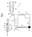
- FIG. 1 An apparatus 10 for evaluating a lubricant, oil, to determine the propensity for coke formation is shown in figure 1 and the apparatus 10 comprises an injector 12, a supply of air 14, a supply of lubricant e.g. oil, 16, a chamber 18 and a test pipe 20.
- the supply of air 14 is arranged to supply air to the injector 12 and the supply of lubricant, oil, 16 is arranged to supply lubricant, oil, to the injector 12.
- the injector 12 is arranged to atomise the lubricant, oil, and supply the air and atomised lubricant, oil, into a chamber 18.
- the chamber 18 is arranged to supply atomised lubricant, oil, and air to the test pipe 20 via a conduit 19 and the heater 22 is arranged around the test pipe 20 to heat the test pipe 20 and thus heat the atomised lubricant, oil, in the test pipe 20.
- the chamber 18 is arranged to return, supply, liquid, un-atomised, lubricant, oil, back to the supply of lubricant, oil, 16 via a conduit 21.
- the supply of lubricant, oil, 16 is arranged to supply the lubricant, oil, to the injector 12 via a conduit 23, a pump 24 and a conduit 25.
- the supply of lubricant, oil, 16 is actually a reservoir.
- the heater 22 comprises a heating block 26 arranged around the test pipe 20 and for example comprises a brass heating block.
- the injector 12 comprises an inner cylindrical member 11 and a coaxial outer cylindrical member 13.
- An inner flow path 15 for air is defined by the inner cylindrical member 11.
- a coaxial outer annular flow path 17 for lubricant, oil, is defined between the inner cylindrical member 11 and the outer cylindrical member 13.
- air and lubricant, oil are supplied to the injector 12 and the injector atomises some of the lubricant, oil to form a lubricant mist, an oil mist, in the air even at ambient temperatures.
- the lubricant, oil is atomised by the shearing force of the air expanding out of the injector 12 into the chamber 18.
- the lubricant flows along the outer annular flow path 17 between the inner and outer cylindrical members 11 and 13 and the air flows along the inner flow path 15 within the inner cylindrical member 11.
- the lubricant, oil is atomised at the downstream end 11B of the inner cylindrical member 11.
- the lubricant, oil is atomised due to the air expanding out of the inner cylindrical member 11 and producing shearing of the lubricant, oil, immediately around the air. The shearing action breaks the lubricant, oil, into small droplets, atomises the lubricant, oil.
- the atomised lubricant, oil e.g. the lubricant, oil, droplets, is carried by the flow of air through the chamber 18 and the conduit 19 to the test pipe 20. Any un-atomised lubricant, oil, is returned by the conduit 21 to the supply of lubricant, oil, 16.
- the atomised lubricant, oil, in the air or the lubricant, oil, mist flows through the test pipe 20, which is heated by the heater 22.
- the heating block 26 produces high wall temperatures in the test pipe 20.
- the lubricant, oil collects, wets out, on the inner surface of the test pipe 20 and the lubricant, oil, on the inner surface of the test pipe 20 is subjected to high temperatures, which results in the degradation of the lubricant, oil, and the formation of carbonaceous deposits, e.g. coke or coking.
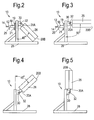
- Figures 2 to 5 show the test pipe 20 of the apparatus 10 of figure 1 mounted on a frame 28.
- the test pipe 20 is variably mounted on the frame 28 such that the orientation of the test pipe 20 relative to the frame 28 is variable.
- the test pipe 20 is pivotably mounted on the frame 28 by a pivot 30 and the test pipe 20 is then locked in the selected orientation by a lock 32.
- the present invention mounts the test pipe 20 on a frame 28 such that the test pipe 20 is variably mounted on the frame 28, then the orientation of the test pipe 20 relative to the frame 28 is varied and the propensity for coke formation at different orientations of the test pipe 20 is determined.
- Figure 2 shows the test pipe 20 arranged at an angle of 45° to the vertical direction and such that the outlet 20B of the test pipe 20 is arranged at a lesser height, lower down than, the inlet 20A.
- Figure 3 shows the test pipe 20 arranged at an angle of 90° to the vertical direction, e.g. horizontal, and such that the outlet 20B of the test pipe 20 is arranged at the same height as the inlet 20A.
- Figure 4 shows the test pipe 20 arranged at an angle of 45° to the vertical direction and such that the outlet 20B of the test pipe 20 is arranged at a greater height, higher up than, the inlet 20A.
- Figure 5 shows the test pipe 20 arranged parallel to the vertical direction, e.g. vertical, and such that the outlet 20B of the test pipe 20 is arranged at a greater height than the inlet 20A.
- HPC oil is high performance capability oil and defined in SAEAS 5780. HPC oils produce less carbonaceous deposits, coking, than standard oils according to the apparatus.
- Figure 6 is a graph of mass of deposit versus oil type tested in the apparatus according to the present invention and it is seen that the mass of deposit for HPC oils is less than that for standard oils.
- HPC oils produce less carbonaceous deposits, coking, than standard oils on aero gas turbine engine vent pipes, e.g. gas turbine engine lubricant system vent pipes.
- the apparatus for evaluating a lubricant, oil, to determine the propensity for coke formation is able to differentiate between different orientations of the test pipe.
- a test pipe arranged vertically produces more carbonaceous deposits, coking, than a test pipe arranged at an angle below the horizontal, e.g. with the outlet of the test pipe at lesser height than the inlet of the test pipe.
- Figure 7 is a graph of mass of deposit versus temperature for a vertical test pipe and a below horizontal test pipe for lubricant, oil, tested in the apparatus according to the present invention and it is seen that the mass of deposit for a vertical test pipe is greater than for a below horizontal test pipe.
- a vertical vent pipe on an aero gas turbine engine produces more deposition, coking, than a below horizontal vent pipe on an aero gas turbine engine.
- the present invention is able to simulate a vent pipe of a lubricant system of an aero gas turbine engine and in particular the variable positioning of the test pipe is able to simulate different angles of vent pipe of a lubricant system on different aero gas turbine engines.
Landscapes
- Engineering & Computer Science (AREA)
- Chemical & Material Sciences (AREA)
- Health & Medical Sciences (AREA)
- Life Sciences & Earth Sciences (AREA)
- Biochemistry (AREA)
- General Health & Medical Sciences (AREA)
- General Physics & Mathematics (AREA)
- Immunology (AREA)
- Pathology (AREA)
- Analytical Chemistry (AREA)
- Physics & Mathematics (AREA)
- Combustion & Propulsion (AREA)
- General Engineering & Computer Science (AREA)
- Mechanical Engineering (AREA)
- Chemical Kinetics & Catalysis (AREA)
- Medicinal Chemistry (AREA)
- Food Science & Technology (AREA)
- Oil, Petroleum & Natural Gas (AREA)
- General Chemical & Material Sciences (AREA)
- Production Of Liquid Hydrocarbon Mixture For Refining Petroleum (AREA)
Applications Claiming Priority (1)
| Application Number | Priority Date | Filing Date | Title |
|---|---|---|---|
| GBGB0810299.8A GB0810299D0 (en) | 2008-06-06 | 2008-06-06 | An apparatus and method for evaluating a hydrocarbon to determine the propensity for coke formation |
Publications (2)
| Publication Number | Publication Date |
|---|---|
| EP2131179A2 true EP2131179A2 (de) | 2009-12-09 |
| EP2131179A3 EP2131179A3 (de) | 2014-04-16 |
Family
ID=39638233
Family Applications (1)
| Application Number | Title | Priority Date | Filing Date |
|---|---|---|---|
| EP09251296.1A Withdrawn EP2131179A3 (de) | 2008-06-06 | 2009-05-12 | Vorrichtung und Verfahren zur Beurteilung eines Kohlenwasserstoffs, um die Neigung zur Koksbildung zu bestimmen |
Country Status (3)
| Country | Link |
|---|---|
| US (1) | US8309363B2 (de) |
| EP (1) | EP2131179A3 (de) |
| GB (1) | GB0810299D0 (de) |
Cited By (2)
| Publication number | Priority date | Publication date | Assignee | Title |
|---|---|---|---|---|
| WO2012118936A1 (en) * | 2011-03-03 | 2012-09-07 | Phillips 66 Company | Measuring coking propensity |
| RU2785434C1 (ru) * | 2022-07-21 | 2022-12-07 | Федеральное автономное учреждение "25 Государственный научно-исследовательский институт химмотологии Министерства обороны Российской Федерации" | Установка для оценки склонности дизельных топлив к образованию отложений на деталях форсунки |
Families Citing this family (5)
| Publication number | Priority date | Publication date | Assignee | Title |
|---|---|---|---|---|
| CN102818741A (zh) * | 2011-06-08 | 2012-12-12 | 重庆车辆检测研究院有限公司 | 车用油管燃油渗透率测试设备 |
| CN104034623B (zh) * | 2013-03-06 | 2016-08-10 | 中国石油天然气股份有限公司 | 一种船用中速机润滑油清净性的试验方法及设备 |
| US10704734B2 (en) | 2017-08-22 | 2020-07-07 | General Electric Company | Method and apparatus for determining lubricant contamination or deterioration in an engine |
| JP7540723B2 (ja) | 2021-12-01 | 2024-08-27 | 大同化学株式会社 | 熱劣化再現装置および熱劣化再現試験方法 |
| CN116106156A (zh) * | 2022-12-20 | 2023-05-12 | 珠海三泰新材料有限公司 | 一种n-甲基吡咯烷酮结焦性能评价装置及评价方法 |
Family Cites Families (14)
| Publication number | Priority date | Publication date | Assignee | Title |
|---|---|---|---|---|
| US1940955A (en) * | 1927-04-04 | 1933-12-26 | Heat Treating Company | Process and apparatus for refining mineral oils |
| US1983386A (en) * | 1931-01-02 | 1934-12-04 | Gen Electric | Combustion arrangement for oil burners |
| US3108468A (en) * | 1960-04-29 | 1963-10-29 | Standard Oil Co | Engine fuel test device |
| US3248927A (en) * | 1964-01-07 | 1966-05-03 | Sinclair Research Inc | Coking test |
| JPS5250306A (en) * | 1975-10-22 | 1977-04-22 | Kureha Chem Ind Co Ltd | Method and apparatus for decoking |
| GB2129710B (en) * | 1982-10-27 | 1986-04-23 | Cabot Corp | Carbon black burner |
| DE3535107A1 (de) * | 1985-10-02 | 1987-04-09 | Mtu Muenchen Gmbh | Versorgungssystem von lagern |
| US4985136A (en) * | 1987-11-05 | 1991-01-15 | Bartholic David B | Ultra-short contact time fluidized catalytic cracking process |
| US5693874A (en) * | 1996-10-11 | 1997-12-02 | Southwest Research Institute | Test apparatus and method for determining deposit formation characteristics of fuels |
| US20030201334A1 (en) * | 2002-04-24 | 2003-10-30 | Wells Jan W. | Liquid feed atomization |
| CA2404798C (en) * | 2002-09-24 | 2007-02-20 | Edward W. Chan | Nozzle/mixer assembly |
| FR2880689A1 (fr) | 2005-01-10 | 2006-07-14 | Snecma Moteurs Sa | Procede d'analyse de cokefaction d'une huile pour turbomoteur. |
| US7550063B2 (en) * | 2005-08-26 | 2009-06-23 | Altene (Canada) Inc. | Method and apparatus for cracking hydrocarbons |
| FR2903450B1 (fr) * | 2006-07-07 | 2013-03-01 | Snecma | Procede de traitement des rejets d'huile dans un moteur a turbine a gaz |
-
2008
- 2008-06-06 GB GBGB0810299.8A patent/GB0810299D0/en not_active Ceased
-
2009
- 2009-05-11 US US12/453,429 patent/US8309363B2/en not_active Expired - Fee Related
- 2009-05-12 EP EP09251296.1A patent/EP2131179A3/de not_active Withdrawn
Non-Patent Citations (1)
| Title |
|---|
| None * |
Cited By (3)
| Publication number | Priority date | Publication date | Assignee | Title |
|---|---|---|---|---|
| WO2012118936A1 (en) * | 2011-03-03 | 2012-09-07 | Phillips 66 Company | Measuring coking propensity |
| RU2785434C1 (ru) * | 2022-07-21 | 2022-12-07 | Федеральное автономное учреждение "25 Государственный научно-исследовательский институт химмотологии Министерства обороны Российской Федерации" | Установка для оценки склонности дизельных топлив к образованию отложений на деталях форсунки |
| RU2785434C9 (ru) * | 2022-07-21 | 2022-12-15 | Федеральное автономное учреждение "25 Государственный научно-исследовательский институт химмотологии Министерства обороны Российской Федерации" | Установка для оценки склонности дизельных топлив к образованию отложений на деталях форсунки |
Also Published As
| Publication number | Publication date |
|---|---|
| EP2131179A3 (de) | 2014-04-16 |
| GB0810299D0 (en) | 2008-07-09 |
| US8309363B2 (en) | 2012-11-13 |
| US20090305428A1 (en) | 2009-12-10 |
Similar Documents
| Publication | Publication Date | Title |
|---|---|---|
| EP2131179A2 (de) | Vorrichtung und Verfahren zur Beurteilung eines Kohlenwasserstoffs, um die Neigung zur Koksbildung zu bestimmen | |
| Vuk et al. | The measurement and analysis of the physical character of diesel particulate emissions | |
| EP2179169B1 (de) | Vorrichtung und verfahren zur überprüfung einer brennstoffeinspritzdüse | |
| Rizk et al. | Drop-size distribution characteristics of spill-return atomizers | |
| Wurster et al. | On the relationship of drop entrainment with bubble formation rates in oil mist filters | |
| US6739184B2 (en) | Method and apparatus for measuring effects of exhaust gas recirculation deposits | |
| Buchmüller | Influence of pressure on Leidenfrost effect | |
| US20120090384A1 (en) | Carbon Deposit Simulation Bench And Methods Therefor | |
| CN115356094B (zh) | 一种发动机油气分离器综合性能测试装置 | |
| Ehteram et al. | Investigation of fine droplet generation from hot engine oil by impinging gas jets onto liquid surface | |
| Yilmaz et al. | An experimental and theoretical study of the contribution of oil evaporation to oil consumption | |
| Park et al. | Transitional instability of a pressure-swirl atomizer due to air-core eruption at low temperature | |
| Chaker | Key parameters for the performance of impaction-pin nozzles used in inlet fogging of gas turbine engines | |
| Shojaeefard et al. | Taguchi optimization of micron sized lubricant oil droplet deposition on a hot plate | |
| Dombrovskii et al. | Atomization of superheated water: Results from experimental studies | |
| CN108713140B (zh) | 用于对燃料(特别是在飞行器中使用的燃料)中的沉积物形成的敏感度进行分析的设备 | |
| Safiullah et al. | Investigation of Water Film Dynamics on the Surface of an Airfoil in a High-Speed Flow and Subsequent Ligament Formation and Breakup From the Trailing Edge | |
| Krawczyk et al. | Effect of the air to water ratio on the performance of internal mixing two-fluid atomiser | |
| Cossali et al. | Secondary droplet atomisation from single drop impact on heated surfaces | |
| Montanaro et al. | Influence of the nozzle geometry of a diesel single-hole injector on liquid and vapor phase distributions at engine-like conditions | |
| CN111896423B (zh) | 汽车油箱加油原始碳氢排放量的测试装置及测试方法和活性炭罐吸附容量的验证装置及验证方法 | |
| Klyus et al. | Residual fuel atomization process simulation | |
| Avulapati et al. | An experimental study on effervescent atomization of bio-oil fuels | |
| Mousapour Khaneshan et al. | Effect of surface temperature on the impaction and deposition of micron-sized engine oil particles on a heated flat plate | |
| Ahmed | Multitude Characterization and Prediction of DOE Advanced Biofuels Properties |
Legal Events
| Date | Code | Title | Description |
|---|---|---|---|
| PUAI | Public reference made under article 153(3) epc to a published international application that has entered the european phase |
Free format text: ORIGINAL CODE: 0009012 |
|
| AK | Designated contracting states |
Kind code of ref document: A2 Designated state(s): AT BE BG CH CY CZ DE DK EE ES FI FR GB GR HR HU IE IS IT LI LT LU LV MC MK MT NL NO PL PT RO SE SI SK TR |
|
| PUAL | Search report despatched |
Free format text: ORIGINAL CODE: 0009013 |
|
| AK | Designated contracting states |
Kind code of ref document: A3 Designated state(s): AT BE BG CH CY CZ DE DK EE ES FI FR GB GR HR HU IE IS IT LI LT LU LV MC MK MT NL NO PL PT RO SE SI SK TR |
|
| AX | Request for extension of the european patent |
Extension state: AL BA RS |
|
| RIC1 | Information provided on ipc code assigned before grant |
Ipc: G01N 5/00 20060101ALI20140307BHEP Ipc: G01N 33/28 20060101ALI20140307BHEP Ipc: G01N 5/02 20060101ALI20140307BHEP Ipc: G01N 33/26 20060101ALI20140307BHEP Ipc: F02K 1/00 20060101ALN20140307BHEP Ipc: G01N 5/04 20060101AFI20140307BHEP Ipc: F02C 7/14 20060101ALN20140307BHEP |
|
| 17P | Request for examination filed |
Effective date: 20141015 |
|
| RAP1 | Party data changed (applicant data changed or rights of an application transferred) |
Owner name: ROLLS-ROYCE PLC |
|
| STAA | Information on the status of an ep patent application or granted ep patent |
Free format text: STATUS: EXAMINATION IS IN PROGRESS |
|
| 17Q | First examination report despatched |
Effective date: 20170130 |
|
| STAA | Information on the status of an ep patent application or granted ep patent |
Free format text: STATUS: THE APPLICATION IS DEEMED TO BE WITHDRAWN |
|
| 18D | Application deemed to be withdrawn |
Effective date: 20170610 |