EP2131134B1 - A method for applying a closing plate to an end of a tubular element - Google Patents
A method for applying a closing plate to an end of a tubular element Download PDFInfo
- Publication number
- EP2131134B1 EP2131134B1 EP09161571.6A EP09161571A EP2131134B1 EP 2131134 B1 EP2131134 B1 EP 2131134B1 EP 09161571 A EP09161571 A EP 09161571A EP 2131134 B1 EP2131134 B1 EP 2131134B1
- Authority
- EP
- European Patent Office
- Prior art keywords
- tubular element
- plate
- annular seating
- annular
- perimeter
- Prior art date
- Legal status (The legal status is an assumption and is not a legal conclusion. Google has not performed a legal analysis and makes no representation as to the accuracy of the status listed.)
- Active
Links
Images

Classifications
-
- F—MECHANICAL ENGINEERING; LIGHTING; HEATING; WEAPONS; BLASTING
- F28—HEAT EXCHANGE IN GENERAL
- F28F—DETAILS OF HEAT-EXCHANGE AND HEAT-TRANSFER APPARATUS, OF GENERAL APPLICATION
- F28F9/00—Casings; Header boxes; Auxiliary supports for elements; Auxiliary members within casings
- F28F9/26—Arrangements for connecting different sections of heat-exchange elements, e.g. of radiators
- F28F9/262—Arrangements for connecting different sections of heat-exchange elements, e.g. of radiators for radiators
- F28F9/268—Arrangements for connecting different sections of heat-exchange elements, e.g. of radiators for radiators by permanent joints, e.g. by welding
-
- F—MECHANICAL ENGINEERING; LIGHTING; HEATING; WEAPONS; BLASTING
- F28—HEAT EXCHANGE IN GENERAL
- F28F—DETAILS OF HEAT-EXCHANGE AND HEAT-TRANSFER APPARATUS, OF GENERAL APPLICATION
- F28F9/00—Casings; Header boxes; Auxiliary supports for elements; Auxiliary members within casings
- F28F9/02—Header boxes; End plates
-
- F—MECHANICAL ENGINEERING; LIGHTING; HEATING; WEAPONS; BLASTING
- F28—HEAT EXCHANGE IN GENERAL
- F28D—HEAT-EXCHANGE APPARATUS, NOT PROVIDED FOR IN ANOTHER SUBCLASS, IN WHICH THE HEAT-EXCHANGE MEDIA DO NOT COME INTO DIRECT CONTACT
- F28D21/00—Heat-exchange apparatus not covered by any of the groups F28D1/00 - F28D20/00
- F28D2021/0019—Other heat exchangers for particular applications; Heat exchange systems not otherwise provided for
- F28D2021/0035—Other heat exchangers for particular applications; Heat exchange systems not otherwise provided for for domestic or space heating, e.g. heating radiators
-
- F—MECHANICAL ENGINEERING; LIGHTING; HEATING; WEAPONS; BLASTING
- F28—HEAT EXCHANGE IN GENERAL
- F28F—DETAILS OF HEAT-EXCHANGE AND HEAT-TRANSFER APPARATUS, OF GENERAL APPLICATION
- F28F2220/00—Closure means, e.g. end caps on header boxes or plugs on conduits
-
- F—MECHANICAL ENGINEERING; LIGHTING; HEATING; WEAPONS; BLASTING
- F28—HEAT EXCHANGE IN GENERAL
- F28F—DETAILS OF HEAT-EXCHANGE AND HEAT-TRANSFER APPARATUS, OF GENERAL APPLICATION
- F28F2275/00—Fastening; Joining
- F28F2275/12—Fastening; Joining by methods involving deformation of the elements
- F28F2275/122—Fastening; Joining by methods involving deformation of the elements by crimping, caulking or clinching
Definitions
- the present invention relates to an original method for applying a metal plate to an end of a tubular element, also made of metal, with the aim of closing a head thereof.
- heating radiators which are constituted by a pair of manifolds, arranged vertically, mutually parallel and interconnected by a plurality of conduits, arranged perpendicular at different heights.
- the upper and lower ends of the vertical manifolds are closed by relative plates having profiles which correspond to the section of the manifolds themselves, which are preferably semi-oval.
- the plates can be solid or can afford, in a central zone thereof, a threaded collar for connection of the radiator to the water line of the heating plant.
- a first known method comprises welding the plate to the tubular element, with the drawbacks which this leads to in terms of time and costs for the use of specialised personnel, needed not only for the welding, but also for the following lapping and seal control operations.
- a further known method includes realising, in the edge of the plate: a small step destined to define a rest for the tubular element and for centring, with respect to the tubular element, the plate itself, thanks to its partial insertion in the mouth of the tubular element.
- the result of the operation in particular in relation to the seal, depends on a correct spreading of the paste over the whole contact perimeter.
- PCT/EP2007061948 relating to a "Plate couplable to an opening edge provided in a tubular element, and a method for constraining the plate to the edge.
- the above application relates to a plate internally provided with a first annular channel in which a ring of low-fusion point brazing material is blocked; further annular channels are arrayed spoke-fashion from the first annular channel and extend towards the edge.
- the junction line between the plate and the tubular element is on the flanks thereof; if the fixing is done by welding, the aesthetic result is not appealing even after lapping, while with the heat-welding paste or the ring of fusible material the situation is improved, although the line is still visible as it is highlighted by the subsequent enamelling.
- DE3936251 which represents the preamble of claim 1 discloses a refrigerant receiver for use in motor vehicle air conditioner, which has a tubular body, in which an annular seating is afforded at one of its open ends, the seating being defined by an upper and a lower projection made by means of electromagnetic forming.
- DE3936251 also discloses a bottom closure with an obliquely inclined perimeter which gives the closure a truncoconical conformation, with the peripheral edge of the bottom closure being clamped between the lower and the upper projection.
- the aim of the present invention is to provide a method for applying a closing plate to the end of a tubular element, which enables obtaining a mechanically stable joint without the use of any extra material, and which at the same time guarantees an aesthetically improved result with respect to what can be obtained with traditional methods.
- a further aim of the invention relates to the providing of a valid method even where a sealed coupling is to be achieved, by predisposing special operating and/or enactment stages which are similar to those in the prior art.
- a still further aim of the process consists in being defined by simple and rapid actuation stages, which can be realised with constant results, using equipment having contained costs and independently of the ability of the personnel doing the operations.
- a further aim of the invention is to provide a method which can be used both with solid plates and with plates having a threaded central sleeve.
- 1 denotes a metal tubular element, for example a metal tubular element 1 which is of the type used in a thermal radiator for installation in a bathroom, and is applicable to one of the two vertical manifolds, to which reference was made in the preamble hereto.
- the ends of the tubular element 1 are destined to be sealedly closed by metal plates which can be solid, as in a first embodiment denoted by 2, or, in a second embodiment denoted by 20, can afford a sleeve 21 in a central zone thereof, which sleeve 21 is internally threaded for connecting the radiator to the water line of the heating plant ( figure 1 ).
- the method of the present invention concerns stages which involve both the preparation of the end of the tubular element 1 and the realisation of the plate 2, 20 and stages which relate to mutual assembly thereof.
- the preparation of the end of the tubular element consists in realising, in the mouth 10 thereof, an annular seating 12 having a predetermined depth P shaped to define a perimeter rest step 13 in a relative bottom situated internally of the tubular element 1.
- the annular seating 12 is obtained by means of successive operations of cold plastic deformation, in particular:
- annular lip 11 is thus defined externally on the annular seating 12, which lip 11 is slimmer than the border of the tubular element 1 (see also figure 3 ).
- a stage of rounding the edge 110 of the annular lip ( figure 4 ) is included in the preparation of the tubular element 1.
- the realisation of the plate 2, 20 involves shaping it (in plan view) such as to obtain a profile which is complementary to the profile of the annular seating 12 ( figure 1 ), with a cutting action such that the perimeter surfaces 22 which result have an oblique inclination, thus determining a truncoconical conformation of the plate 2, 20 ( figure 2 ), the thickness S of which must be equal to the depth P of the annular seating 12, at least over a certain width of the relative perimeter edge 23.
- the plate 2, 20 is preferably fashioned from a flat metal sheet having a constant thickness S, which is equal to the thickness S of the depth P of the seating 12.
- the stage of realisation includes drawing, perforating and tapping operations, apart from the operations described above.
- Sealing means 30 are associated to the plates 2, 20 of the embodiment, which sealing means 30 are destined to guarantee liquid seal of the coupling between the plates 2, 20 and the tubular element 1; the sealing means 30, not illustrated in detail, are advantageously of the type described in the patent application mentioned herein above, and comprise a ring 31 of low-fusion point brazing material, schematically denoted by broken lines in figure 2 .
- the ring 31 is fixed by friction force to an annular channel 32 (visible in the plate 20 in figure 2 ) connected to other channels developing spoke-fashion towards the edge (not illustrated).
- the stages of the method for application of the plate 2, 20 to the tubular element 1 comprise:
- the method comprises a supplementary stage, using the sealing means 30.
- this stage consists in heating the tubular element-plate assembly to a temperature above the fusion temperature of the ring 31, for a predetermined time, followed by a cooling of the assembly in order to obtain a new solidification of the metal of the ring 31, distributed in the contact zones between the plate 2, 20 and the tubular element 1.
- the sealed coupling between the plate 2, 20 and the tubular element 1 can obviously be realised, alternatively to what has been described, by a bead of heat-welding paste, mentioned in the preamble, distribution, in preparation, between the contact zones.
- the plate is unremovably fixed merely by mechanical action, entirely contrary to all the known solutions, thanks to the snug fit created by the profiling of the annular lip of the tubular element.
- the conformation of the seating, and consequently the plate locates the joint line between the two parts in the head of the tubular element, thus in a much less visible zone than on the flank; this leads to obvious benefits from the overall aesthetic point of view.
- joint line lies on a plane, so that any lapping or sanding operations which might be desired to further reduce the visibility of the line are evidently very simple and effective.
- the described method enables easily obtaining couplings with or without seal, according to needs.
- the need to realise the step in the edge of the plate is eliminated and, consequently, the plate can be slimmer; by way of example, metal sheeting of 2 mm thickness can be used instead of the 3.5 mm thickness required for prior-art plates.
- the proposed method is advantageous, in general, for all cases in which the application of a metal plate for closing the head of a metal tube is required; in the particular technical sector of the described example, the fact that all the coupling stages of the plate are the same both when the plate is solid and when it is provided with a threaded central sleeve is much appreciated.
Landscapes
- Engineering & Computer Science (AREA)
- Physics & Mathematics (AREA)
- Thermal Sciences (AREA)
- Mechanical Engineering (AREA)
- General Engineering & Computer Science (AREA)
- Lining Or Joining Of Plastics Or The Like (AREA)
- Pipe Accessories (AREA)
- Standing Axle, Rod, Or Tube Structures Coupled By Welding, Adhesion, Or Deposition (AREA)
- Pressure Vessels And Lids Thereof (AREA)
- Steam Or Hot-Water Central Heating Systems (AREA)
- Photoreceptors In Electrophotography (AREA)
- Shaping Of Tube Ends By Bending Or Straightening (AREA)
Description
- The present invention relates to an original method for applying a metal plate to an end of a tubular element, also made of metal, with the aim of closing a head thereof.
- The need to perform the above operation is frequent and, in accordance with specific needs, the method used is the one which seems most appropriate to the particular case; for example, it may be necessary to guarantee a liquid or a gas seal coupling, or it may not.
- In the field of thermal sanitary plants for bathrooms and the like, the use of heating radiators is known, which are constituted by a pair of manifolds, arranged vertically, mutually parallel and interconnected by a plurality of conduits, arranged perpendicular at different heights.
- The upper and lower ends of the vertical manifolds are closed by relative plates having profiles which correspond to the section of the manifolds themselves, which are preferably semi-oval.
- The plates can be solid or can afford, in a central zone thereof, a threaded collar for connection of the radiator to the water line of the heating plant.
- In the above-cited case, it is obvious that the joint between the plate and the end of the manifold must be one that ensures liquid seal.
- A first known method comprises welding the plate to the tubular element, with the drawbacks which this leads to in terms of time and costs for the use of specialised personnel, needed not only for the welding, but also for the following lapping and seal control operations.
- A further known method includes realising, in the edge of the plate: a small step destined to define a rest for the tubular element and for centring, with respect to the tubular element, the plate itself, thanks to its partial insertion in the mouth of the tubular element.
- Between the contact zones of the plate and the end of the tubular element, before mounting a special heat-welding paste is manually applied, which paste, following a suitable heat treatment, makes the fixing unremovable as well as guaranteeing a seal against leaks.
- The result of the operation, in particular in relation to the seal, depends on a correct spreading of the paste over the whole contact perimeter.
- In order to obviate the limits of the above solution, the applicant filed a PCT/EP application,
PCT/EP2007061948 - The above application relates to a plate internally provided with a first annular channel in which a ring of low-fusion point brazing material is blocked; further annular channels are arrayed spoke-fashion from the first annular channel and extend towards the edge.
- After mounting the plate on the tubular element there is a stage of heating which fuses the ring, the material of which, by capillarity, runs along the channels and reaches all the contact zones between the plate and the tubular element; the following cooling enables solidification of the molten metal, guaranteeing joint stability and seal.
- The presence of a ring of fusible material, the same for all plates, guarantees absolute constancy and repeatability of the result, independently of the position assumed in the heating kiln.
- In all the known solutions described above, the junction line between the plate and the tubular element is on the flanks thereof; if the fixing is done by welding, the aesthetic result is not appealing even after lapping, while with the heat-welding paste or the ring of fusible material the situation is improved, although the line is still visible as it is highlighted by the subsequent enamelling.
- The need to realise a step in the plate means that the plate must have a total thickness which is sufficient to leave, at the edge thereof, an adequate residual thickness; in practice, these plates have a thickness of in the region of 3.5 mm.
DE3936251 which represents the preamble ofclaim 1 discloses a refrigerant receiver for use in motor vehicle air conditioner, which has a tubular body, in which an annular seating is afforded at one of its open ends, the seating being defined by an upper and a lower projection made by means of electromagnetic forming. -
DE3936251 also discloses a bottom closure with an obliquely inclined perimeter which gives the closure a truncoconical conformation, with the peripheral edge of the bottom closure being clamped between the lower and the upper projection. - The aim of the present invention is to provide a method for applying a closing plate to the end of a tubular element, which enables obtaining a mechanically stable joint without the use of any extra material, and which at the same time guarantees an aesthetically improved result with respect to what can be obtained with traditional methods.
- A further aim of the invention relates to the providing of a valid method even where a sealed coupling is to be achieved, by predisposing special operating and/or enactment stages which are similar to those in the prior art.
- A still further aim of the process consists in being defined by simple and rapid actuation stages, which can be realised with constant results, using equipment having contained costs and independently of the ability of the personnel doing the operations.
- A further aim of the invention is to provide a method which can be used both with solid plates and with plates having a threaded central sleeve.
- The characteristics of the method of the invention will better emerge from the following description, in accordance with what is set out in the claims and with the aid of the accompanying figures of the tables of drawings, in which:
-
figure 1 is an exploded perspective view of a portion of a tubular element and two different plates to be alternatively coupled thereto; -
figure 2 is a front view of the same pieces offigure 1 , which highlights constructional aspects of the plates and a stage of the method relating to the tubular element; -
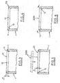
figures 3 and 4 illustrate, in large-scale, corresponding axial sections of the tubular element, following realisation of successive operating stages of the method; -
figure 5 illustrates, in a similar view to precedingfigures 3 and 4 , the following stage of insertion of the plate into the tubular element; -
figure 6 illustrates, in a similar view tofigure 5 , the following stage of mechanical blocking of the plate to the element. - With reference to the figures of the drawings, 1 denotes a metal tubular element, for example a metal
tubular element 1 which is of the type used in a thermal radiator for installation in a bathroom, and is applicable to one of the two vertical manifolds, to which reference was made in the preamble hereto. - The ends of the
tubular element 1 are destined to be sealedly closed by metal plates which can be solid, as in a first embodiment denoted by 2, or, in a second embodiment denoted by 20, can afford asleeve 21 in a central zone thereof, whichsleeve 21 is internally threaded for connecting the radiator to the water line of the heating plant (figure 1 ). - The method of the present invention concerns stages which involve both the preparation of the end of the
tubular element 1 and the realisation of theplate - The preparation of the end of the tubular element consists in realising, in the
mouth 10 thereof, anannular seating 12 having a predetermined depth P shaped to define aperimeter rest step 13 in a relative bottom situated internally of thetubular element 1. - According to the invention, the
annular seating 12 is obtained by means of successive operations of cold plastic deformation, in particular: - calibrating (denoted by C in
figure 2 ) an inside of thetubular element 1, starting from themouth 10 and going down to a predetermined depth L (seefigure 2 again); - moulding the
annular seating 12, having the same shape as the calibrated internal section of thetubular element 1 and having uniformly larger dimensions than the calibrated internal section, such that the moulding action causes material to be pressed towards the inside in order to form the above-mentioned perimeter rest step 13 (figure 3 ). - An annular lip 11 is thus defined externally on the
annular seating 12, which lip 11 is slimmer than the border of the tubular element 1 (see alsofigure 3 ). - In a preferred embodiment of the method, a stage of rounding the
edge 110 of the annular lip (figure 4 ) is included in the preparation of thetubular element 1. - The realisation of the
plate figure 1 ), with a cutting action such that theperimeter surfaces 22 which result have an oblique inclination, thus determining a truncoconical conformation of theplate 2, 20 (figure 2 ), the thickness S of which must be equal to the depth P of theannular seating 12, at least over a certain width of therelative perimeter edge 23. - The
plate seating 12. - In order to obtain the
plate 20 in which the threadedsleeve 21 is afforded, the stage of realisation includes drawing, perforating and tapping operations, apart from the operations described above. - Sealing means 30 are associated to the
plates plates tubular element 1; the sealing means 30, not illustrated in detail, are advantageously of the type described in the patent application mentioned herein above, and comprise aring 31 of low-fusion point brazing material, schematically denoted by broken lines infigure 2 . - The
ring 31 is fixed by friction force to an annular channel 32 (visible in theplate 20 infigure 2 ) connected to other channels developing spoke-fashion towards the edge (not illustrated). - The stages of the method for application of the
plate tubular element 1 comprise: - inserting the
plate annular seating 12, such that theperimeter cut surfaces 22 exhibit respective converging inclinations in a vertex located externally on the tubular element 1 (figure 5 ); - fashioning the annular lip 11 in order to superpose it on the perimeter cut
surfaces 22 and obtaining, in this way, a mechanical blocking of theplate figure 6 ). - On conclusion of this last operation, as already mentioned, the
plate tubular element 1 and, should the coupling not require further seal characteristics, the application might be considered complete. - In the specific case, however, that a seal is required, the method comprises a supplementary stage, using the sealing means 30.
- With reference to the described example, this stage consists in heating the tubular element-plate assembly to a temperature above the fusion temperature of the
ring 31, for a predetermined time, followed by a cooling of the assembly in order to obtain a new solidification of the metal of thering 31, distributed in the contact zones between theplate tubular element 1. - The sealed coupling between the
plate tubular element 1 can obviously be realised, alternatively to what has been described, by a bead of heat-welding paste, mentioned in the preamble, distribution, in preparation, between the contact zones. - From the above the positive characteristics of the described method clearly emerge, which characteristics enable the aims indicated in the preamble to be fully attained.
- Firstly, the plate is unremovably fixed merely by mechanical action, entirely contrary to all the known solutions, thanks to the snug fit created by the profiling of the annular lip of the tubular element.
- Further, the conformation of the seating, and consequently the plate, locates the joint line between the two parts in the head of the tubular element, thus in a much less visible zone than on the flank; this leads to obvious benefits from the overall aesthetic point of view.
- Further, the joint line lies on a plane, so that any lapping or sanding operations which might be desired to further reduce the visibility of the line are evidently very simple and effective.
- The described method enables easily obtaining couplings with or without seal, according to needs.
- With the method of the invention, the need to realise the step in the edge of the plate is eliminated and, consequently, the plate can be slimmer; by way of example, metal sheeting of 2 mm thickness can be used instead of the 3.5 mm thickness required for prior-art plates.
- Considering that the above-mentioned plates, in the cited technical sector, are produced in very high numbers, it can be understood how the ensuing savings are of not inconsiderable entity.
- All of the stages of the method are simple and rapid to actuate, with an absolute repeatability in terms of results, by equipment having contained costs, without the need to use specialised personnel.
- The proposed method is advantageous, in general, for all cases in which the application of a metal plate for closing the head of a metal tube is required; in the particular technical sector of the described example, the fact that all the coupling stages of the plate are the same both when the plate is solid and when it is provided with a threaded central sleeve is much appreciated.
- However the above description is intended to be of non-limiting nature, and any modifications to detail in the actuation of the described stages are considered to fall within the ambit of protection thereof, as set out in the following claims.
Claims (5)
- A method for applying a closing plate (2, 20) to an end of a tubular element (1), comprising:realising an annular seating (12) in a mouth (10) of the tubular element (1), which annular seating (12) has a predetermined depth (P) and is shaped such as to define a rest perimeter (13) in a bottom thereof situated internally of the tubular element (1);realising the plate (2, 20), with a plan profile which is complementary to a profile of the annular seating (12), perimeter cut surfaces (22) of the profile being obliquely inclined in order to obtain a truncoconical conformation of the plate (2, 20) and with a thickness (S) of the plate being substantially equal to the depth (P) of the annular seating (12), at least concerning a predetermined width of a perimeter edge (23) thereof;inverting the plate (2, 20) in the annular seating (12), such that the perimeter cut surfaces (22) of the profile exhibit respective inclinations converging to a point located externally of the tubular element (1);fashioning an annular lip (11) of the tubular element (1) located externally on the seating (12), in order to superpose the annular lip (11) onto the perimeter cut surfaces (22), thus obtaining a mechanical blocking of the plate (2, 20) to the tubular element (1);characterized in that the stage of realising the annular seating (12) consists in successive plastic cold-deformation operations of the tubular element (1), and in that the plastic cold-deformation operations comprise:calibrating an inside of the tubular element (1), starting from the mouth (10) and reaching a predetermined depth (L);moulding the annular seating (12) having the same shape as the calibrated interval section of the tubular element (1) and having uniformly larger dimensions than the calibrated internal section of the tubular element (1), such that the moulding action causes some material to be intercepted and pressed towards an inside of the tubular element (1) in order to form the above-mentioned perimeter rest step (13).
- The method of claim 1, characterised in that sealing means (30) are associated to the plate (2, 20), and in that subsequent to the stage of fashioning, the sealing means (30) are activated in order to realise a sealed coupling between the plate (2, 20) and the tubular element (1).
- The method of claim 1 characterised in that it comprises, in the stage of realising the annular seating (12), a rounding of the edge (110) of the annular lip (11).
- The method of claim 1, characterised in that operations for affording an internally-threaded sleeve (21) in a central zone of the plate (2, 20) are comprised during the stage of realising the plate (2, 20).
- The method of claim 4, characterised in that the operations for defining the threaded sleeve (21) comprise operations of drawing, perforating and tapping.
Priority Applications (3)
| Application Number | Priority Date | Filing Date | Title |
|---|---|---|---|
| SI200931106T SI2131134T1 (en) | 2008-06-06 | 2009-05-29 | A method for applying a closing plate to an end of a tubular element |
| PL09161571T PL2131134T3 (en) | 2008-06-06 | 2009-05-29 | A method for applying a closing plate to an end of a tubular element |
| HRP20141252TT HRP20141252T1 (en) | 2008-06-06 | 2014-12-22 | A method for applying a closing plate to an end of a tubular element |
Applications Claiming Priority (1)
| Application Number | Priority Date | Filing Date | Title |
|---|---|---|---|
| IT000357A ITBO20080357A1 (en) | 2008-06-06 | 2008-06-06 | METHOD FOR THE APPLICATION OF A CLOSING PLATE ALL END OF A TUBULAR ELEMENT |
Publications (3)
| Publication Number | Publication Date |
|---|---|
| EP2131134A2 EP2131134A2 (en) | 2009-12-09 |
| EP2131134A3 EP2131134A3 (en) | 2011-01-19 |
| EP2131134B1 true EP2131134B1 (en) | 2014-10-22 |
Family
ID=40301546
Family Applications (1)
| Application Number | Title | Priority Date | Filing Date |
|---|---|---|---|
| EP09161571.6A Active EP2131134B1 (en) | 2008-06-06 | 2009-05-29 | A method for applying a closing plate to an end of a tubular element |
Country Status (8)
| Country | Link |
|---|---|
| EP (1) | EP2131134B1 (en) |
| DK (1) | DK2131134T3 (en) |
| ES (1) | ES2528187T3 (en) |
| HR (1) | HRP20141252T1 (en) |
| IT (1) | ITBO20080357A1 (en) |
| PL (1) | PL2131134T3 (en) |
| PT (1) | PT2131134E (en) |
| SI (1) | SI2131134T1 (en) |
Families Citing this family (1)
| Publication number | Priority date | Publication date | Assignee | Title |
|---|---|---|---|---|
| ITBO20110676A1 (en) * | 2011-11-28 | 2013-05-29 | Valter Lolli | CLOSING PLATE FOR TUBULAR ELEMENTS AND A METHOD OF REALIZING IT |
Family Cites Families (7)
| Publication number | Priority date | Publication date | Assignee | Title |
|---|---|---|---|---|
| GB553626A (en) * | 1942-04-25 | 1943-05-28 | Bundy Tubing Co | Improvements in the manufacture of metal tubes having sealed ends |
| JPH0264855U (en) * | 1988-10-31 | 1990-05-16 | ||
| US5224358A (en) * | 1990-10-04 | 1993-07-06 | Nippondenso Co., Ltd. | Refrigerating apparatus and modulator |
| DE10066393B4 (en) * | 1999-09-10 | 2018-09-20 | Mahle International Gmbh | capacitor |
| US6453697B1 (en) * | 2001-04-23 | 2002-09-24 | Designed Metal Products, Inc. | Seal for vessel and method of forming same |
| JP2003083698A (en) * | 2001-09-07 | 2003-03-19 | Sanden Corp | Heat exchanger and method of manufacturing heat exchanger |
| AU2004318635A1 (en) * | 2004-04-22 | 2005-11-03 | Francesco Gropallo | Furnace brazing process |
-
2008
- 2008-06-06 IT IT000357A patent/ITBO20080357A1/en unknown
-
2009
- 2009-05-29 PL PL09161571T patent/PL2131134T3/en unknown
- 2009-05-29 SI SI200931106T patent/SI2131134T1/en unknown
- 2009-05-29 ES ES09161571.6T patent/ES2528187T3/en active Active
- 2009-05-29 EP EP09161571.6A patent/EP2131134B1/en active Active
- 2009-05-29 DK DK09161571.6T patent/DK2131134T3/en active
- 2009-05-29 PT PT91615716T patent/PT2131134E/en unknown
-
2014
- 2014-12-22 HR HRP20141252TT patent/HRP20141252T1/en unknown
Also Published As
| Publication number | Publication date |
|---|---|
| ITBO20080357A1 (en) | 2009-12-07 |
| SI2131134T1 (en) | 2015-03-31 |
| ES2528187T3 (en) | 2015-02-05 |
| PL2131134T3 (en) | 2015-04-30 |
| EP2131134A2 (en) | 2009-12-09 |
| DK2131134T3 (en) | 2015-01-19 |
| EP2131134A3 (en) | 2011-01-19 |
| PT2131134E (en) | 2015-01-14 |
| HRP20141252T1 (en) | 2015-04-24 |
Similar Documents
| Publication | Publication Date | Title |
|---|---|---|
| EP3143355B1 (en) | Radiator element provided with a hooked closing cap and radiator thereof | |
| CA2557647A1 (en) | Cooktop gasket | |
| DK2131134T3 (en) | A method for placing a sealing plate on an end of a tubular member | |
| IE922446A1 (en) | A method of manufacturing a cooking utensil | |
| EP1471309A2 (en) | Radiant battery adaptable to multipurpose coverings, particularly for house heating systems | |
| US6786521B1 (en) | Composite plug with mesh substrate for use during vehicle manufacture and method of manufacturing the same | |
| US4960628A (en) | Method and apparatus for in situ forming of a wall plate gasket | |
| EP0481303B1 (en) | Cooking pans of capsular base type with a profiled lateral band | |
| KR101338912B1 (en) | Protective cover for duct insulation | |
| EP2009341B1 (en) | Method for obtaining a sealing junction for a rigid pipe intended to convey fluid under pressure | |
| KR100218571B1 (en) | Method of manufactur a cooking vessels | |
| JP2019203549A (en) | Resin pipe for piping connection and connection structure including the same | |
| EP2140185A1 (en) | Plastic based radiator valve and the production method thereof | |
| KR101152146B1 (en) | Water distributing device | |
| CN102439235B (en) | Jet regulator | |
| EP0936411A2 (en) | Assembly system for glass-ceramic cooking plates | |
| WO2008055910A2 (en) | A plate, couplable to an edge of an opening afforded in a tubular element, and a method for constraining the plate to the edge | |
| IE42327B1 (en) | A pipe fitting | |
| EP0487007A2 (en) | Process for the manufacture of radiant panels and the like and radiant panel thus obtained | |
| WO2013080113A2 (en) | A closing plate for hollow tubular elements and a method for realising the closing plate | |
| KR101731556B1 (en) | A windbreak of the portable gas burner | |
| FR2770856A1 (en) | Steam smoothing iron with sectional water reservoir | |
| KR20030062470A (en) | The forming method of pipe fitting by using local rapid heating | |
| JP4168370B2 (en) | Heat exchanger support | |
| JP2020056185A (en) | Flexible drain |
Legal Events
| Date | Code | Title | Description |
|---|---|---|---|
| PUAI | Public reference made under article 153(3) epc to a published international application that has entered the european phase |
Free format text: ORIGINAL CODE: 0009012 |
|
| AK | Designated contracting states |
Kind code of ref document: A2 Designated state(s): AT BE BG CH CY CZ DE DK EE ES FI FR GB GR HR HU IE IS IT LI LT LU LV MC MK MT NL NO PL PT RO SE SI SK TR |
|
| PUAL | Search report despatched |
Free format text: ORIGINAL CODE: 0009013 |
|
| AK | Designated contracting states |
Kind code of ref document: A3 Designated state(s): AT BE BG CH CY CZ DE DK EE ES FI FR GB GR HR HU IE IS IT LI LT LU LV MC MK MT NL NO PL PT RO SE SI SK TR |
|
| AX | Request for extension of the european patent |
Extension state: AL BA RS |
|
| 17P | Request for examination filed |
Effective date: 20110615 |
|
| GRAP | Despatch of communication of intention to grant a patent |
Free format text: ORIGINAL CODE: EPIDOSNIGR1 |
|
| GRAJ | Information related to disapproval of communication of intention to grant by the applicant or resumption of examination proceedings by the epo deleted |
Free format text: ORIGINAL CODE: EPIDOSDIGR1 |
|
| INTG | Intention to grant announced |
Effective date: 20140506 |
|
| RAX | Requested extension states of the european patent have changed |
Extension state: BA Payment date: 20110615 Extension state: AL Payment date: 20110615 Extension state: RS Payment date: 20110615 |
|
| GRAP | Despatch of communication of intention to grant a patent |
Free format text: ORIGINAL CODE: EPIDOSNIGR1 |
|
| INTG | Intention to grant announced |
Effective date: 20140610 |
|
| INTG | Intention to grant announced |
Effective date: 20140617 |
|
| GRAS | Grant fee paid |
Free format text: ORIGINAL CODE: EPIDOSNIGR3 |
|
| GRAA | (expected) grant |
Free format text: ORIGINAL CODE: 0009210 |
|
| AK | Designated contracting states |
Kind code of ref document: B1 Designated state(s): AT BE BG CH CY CZ DE DK EE ES FI FR GB GR HR HU IE IS IT LI LT LU LV MC MK MT NL NO PL PT RO SE SI SK TR |
|
| AX | Request for extension of the european patent |
Extension state: AL BA RS |
|
| REG | Reference to a national code |
Ref country code: GB Ref legal event code: FG4D |
|
| REG | Reference to a national code |
Ref country code: CH Ref legal event code: EP |
|
| REG | Reference to a national code |
Ref country code: AT Ref legal event code: REF Ref document number: 692855 Country of ref document: AT Kind code of ref document: T Effective date: 20141115 |
|
| REG | Reference to a national code |
Ref country code: IE Ref legal event code: FG4D |
|
| REG | Reference to a national code |
Ref country code: DE Ref legal event code: R096 Ref document number: 602009027285 Country of ref document: DE Effective date: 20141204 |
|
| REG | Reference to a national code |
Ref country code: RO Ref legal event code: EPE |
|
| REG | Reference to a national code |
Ref country code: HR Ref legal event code: TUEP Ref document number: P20141252 Country of ref document: HR |
|
| REG | Reference to a national code |
Ref country code: CH Ref legal event code: NV Representative=s name: RIEDERER HASLER AND PARTNER PATENTANWAELTE AG, LI |
|
| REG | Reference to a national code |
Ref country code: PT Ref legal event code: SC4A Free format text: AVAILABILITY OF NATIONAL TRANSLATION Effective date: 20150109 |
|
| REG | Reference to a national code |
Ref country code: DK Ref legal event code: T3 Effective date: 20150116 |
|
| REG | Reference to a national code |
Ref country code: NL Ref legal event code: T3 |
|
| REG | Reference to a national code |
Ref country code: SE Ref legal event code: TRGR |
|
| REG | Reference to a national code |
Ref country code: ES Ref legal event code: FG2A Ref document number: 2528187 Country of ref document: ES Kind code of ref document: T3 Effective date: 20150205 |
|
| REG | Reference to a national code |
Ref country code: LT Ref legal event code: MG4D |
|
| REG | Reference to a national code |
Ref country code: SK Ref legal event code: T3 Ref document number: E 17798 Country of ref document: SK |
|
| REG | Reference to a national code |
Ref country code: GR Ref legal event code: EP Ref document number: 20150400114 Country of ref document: GR Effective date: 20150220 |
|
| REG | Reference to a national code |
Ref country code: HR Ref legal event code: T1PR Ref document number: P20141252 Country of ref document: HR |
|
| PG25 | Lapsed in a contracting state [announced via postgrant information from national office to epo] |
Ref country code: FI Free format text: LAPSE BECAUSE OF FAILURE TO SUBMIT A TRANSLATION OF THE DESCRIPTION OR TO PAY THE FEE WITHIN THE PRESCRIBED TIME-LIMIT Effective date: 20141022 Ref country code: IS Free format text: LAPSE BECAUSE OF FAILURE TO SUBMIT A TRANSLATION OF THE DESCRIPTION OR TO PAY THE FEE WITHIN THE PRESCRIBED TIME-LIMIT Effective date: 20150222 Ref country code: NO Free format text: LAPSE BECAUSE OF FAILURE TO SUBMIT A TRANSLATION OF THE DESCRIPTION OR TO PAY THE FEE WITHIN THE PRESCRIBED TIME-LIMIT Effective date: 20150122 Ref country code: LT Free format text: LAPSE BECAUSE OF FAILURE TO SUBMIT A TRANSLATION OF THE DESCRIPTION OR TO PAY THE FEE WITHIN THE PRESCRIBED TIME-LIMIT Effective date: 20141022 |
|
| REG | Reference to a national code |
Ref country code: PL Ref legal event code: T3 |
|
| PG25 | Lapsed in a contracting state [announced via postgrant information from national office to epo] |
Ref country code: CY Free format text: LAPSE BECAUSE OF FAILURE TO SUBMIT A TRANSLATION OF THE DESCRIPTION OR TO PAY THE FEE WITHIN THE PRESCRIBED TIME-LIMIT Effective date: 20141022 Ref country code: LV Free format text: LAPSE BECAUSE OF FAILURE TO SUBMIT A TRANSLATION OF THE DESCRIPTION OR TO PAY THE FEE WITHIN THE PRESCRIBED TIME-LIMIT Effective date: 20141022 |
|
| REG | Reference to a national code |
Ref country code: DE Ref legal event code: R097 Ref document number: 602009027285 Country of ref document: DE |
|
| PG25 | Lapsed in a contracting state [announced via postgrant information from national office to epo] |
Ref country code: EE Free format text: LAPSE BECAUSE OF FAILURE TO SUBMIT A TRANSLATION OF THE DESCRIPTION OR TO PAY THE FEE WITHIN THE PRESCRIBED TIME-LIMIT Effective date: 20141022 |
|
| PLBE | No opposition filed within time limit |
Free format text: ORIGINAL CODE: 0009261 |
|
| REG | Reference to a national code |
Ref country code: HU Ref legal event code: AG4A Ref document number: E023773 Country of ref document: HU |
|
| STAA | Information on the status of an ep patent application or granted ep patent |
Free format text: STATUS: NO OPPOSITION FILED WITHIN TIME LIMIT |
|
| 26N | No opposition filed |
Effective date: 20150723 |
|
| REG | Reference to a national code |
Ref country code: DK Ref legal event code: EBP Effective date: 20150531 |
|
| PG25 | Lapsed in a contracting state [announced via postgrant information from national office to epo] |
Ref country code: MC Free format text: LAPSE BECAUSE OF FAILURE TO SUBMIT A TRANSLATION OF THE DESCRIPTION OR TO PAY THE FEE WITHIN THE PRESCRIBED TIME-LIMIT Effective date: 20141022 Ref country code: LU Free format text: LAPSE BECAUSE OF FAILURE TO SUBMIT A TRANSLATION OF THE DESCRIPTION OR TO PAY THE FEE WITHIN THE PRESCRIBED TIME-LIMIT Effective date: 20150529 Ref country code: GR Free format text: LAPSE BECAUSE OF NON-PAYMENT OF DUE FEES Effective date: 20151208 |
|
| REG | Reference to a national code |
Ref country code: SK Ref legal event code: MM4A Ref document number: E 17798 Country of ref document: SK Effective date: 20150529 |
|
| REG | Reference to a national code |
Ref country code: NL Ref legal event code: MM Effective date: 20150601 |
|
| REG | Reference to a national code |
Ref country code: IE Ref legal event code: MM4A |
|
| PG25 | Lapsed in a contracting state [announced via postgrant information from national office to epo] |
Ref country code: SE Free format text: LAPSE BECAUSE OF NON-PAYMENT OF DUE FEES Effective date: 20150530 Ref country code: SK Free format text: LAPSE BECAUSE OF NON-PAYMENT OF DUE FEES Effective date: 20150529 |
|
| REG | Reference to a national code |
Ref country code: GR Ref legal event code: ML Ref document number: 20150400114 Country of ref document: GR Effective date: 20151208 |
|
| REG | Reference to a national code |
Ref country code: PT Ref legal event code: MM4A Free format text: LAPSE DUE TO NON-PAYMENT OF FEES Effective date: 20160229 |
|
| PG25 | Lapsed in a contracting state [announced via postgrant information from national office to epo] |
Ref country code: IE Free format text: LAPSE BECAUSE OF NON-PAYMENT OF DUE FEES Effective date: 20150529 Ref country code: BG Free format text: LAPSE BECAUSE OF NON-PAYMENT OF DUE FEES Effective date: 20160331 Ref country code: DK Free format text: LAPSE BECAUSE OF NON-PAYMENT OF DUE FEES Effective date: 20150531 Ref country code: NL Free format text: LAPSE BECAUSE OF NON-PAYMENT OF DUE FEES Effective date: 20150601 |
|
| REG | Reference to a national code |
Ref country code: FR Ref legal event code: PLFP Year of fee payment: 8 |
|
| PG25 | Lapsed in a contracting state [announced via postgrant information from national office to epo] |
Ref country code: PT Free format text: LAPSE BECAUSE OF NON-PAYMENT OF DUE FEES Effective date: 20160229 Ref country code: HU Free format text: LAPSE BECAUSE OF NON-PAYMENT OF DUE FEES Effective date: 20150530 |
|
| REG | Reference to a national code |
Ref country code: AT Ref legal event code: UEP Ref document number: 692855 Country of ref document: AT Kind code of ref document: T Effective date: 20141022 |
|
| PG25 | Lapsed in a contracting state [announced via postgrant information from national office to epo] |
Ref country code: MT Free format text: LAPSE BECAUSE OF FAILURE TO SUBMIT A TRANSLATION OF THE DESCRIPTION OR TO PAY THE FEE WITHIN THE PRESCRIBED TIME-LIMIT Effective date: 20141022 |
|
| REG | Reference to a national code |
Ref country code: FR Ref legal event code: PLFP Year of fee payment: 9 |
|
| REG | Reference to a national code |
Ref country code: HR Ref legal event code: ODRP Ref document number: P20141252 Country of ref document: HR Payment date: 20180522 Year of fee payment: 10 Ref country code: FR Ref legal event code: PLFP Year of fee payment: 10 |
|
| PG25 | Lapsed in a contracting state [announced via postgrant information from national office to epo] |
Ref country code: MK Free format text: LAPSE BECAUSE OF FAILURE TO SUBMIT A TRANSLATION OF THE DESCRIPTION OR TO PAY THE FEE WITHIN THE PRESCRIBED TIME-LIMIT Effective date: 20141022 |
|
| PGFP | Annual fee paid to national office [announced via postgrant information from national office to epo] |
Ref country code: CH Payment date: 20180529 Year of fee payment: 10 Ref country code: HR Payment date: 20180522 Year of fee payment: 10 Ref country code: ES Payment date: 20180604 Year of fee payment: 10 |
|
| PGFP | Annual fee paid to national office [announced via postgrant information from national office to epo] |
Ref country code: SI Payment date: 20180524 Year of fee payment: 10 Ref country code: BE Payment date: 20180525 Year of fee payment: 10 Ref country code: FR Payment date: 20180522 Year of fee payment: 10 |
|
| PGFP | Annual fee paid to national office [announced via postgrant information from national office to epo] |
Ref country code: GB Payment date: 20180522 Year of fee payment: 10 |
|
| REG | Reference to a national code |
Ref country code: HR Ref legal event code: PBON Ref document number: P20141252 Country of ref document: HR Effective date: 20190529 |
|
| REG | Reference to a national code |
Ref country code: CH Ref legal event code: PL |
|
| REG | Reference to a national code |
Ref country code: AT Ref legal event code: MM01 Ref document number: 692855 Country of ref document: AT Kind code of ref document: T Effective date: 20190529 |
|
| GBPC | Gb: european patent ceased through non-payment of renewal fee |
Effective date: 20190529 |
|
| PG25 | Lapsed in a contracting state [announced via postgrant information from national office to epo] |
Ref country code: LI Free format text: LAPSE BECAUSE OF NON-PAYMENT OF DUE FEES Effective date: 20190531 Ref country code: CH Free format text: LAPSE BECAUSE OF NON-PAYMENT OF DUE FEES Effective date: 20190531 Ref country code: AT Free format text: LAPSE BECAUSE OF NON-PAYMENT OF DUE FEES Effective date: 20190529 |
|
| REG | Reference to a national code |
Ref country code: BE Ref legal event code: MM Effective date: 20190531 |
|
| PG25 | Lapsed in a contracting state [announced via postgrant information from national office to epo] |
Ref country code: SI Free format text: LAPSE BECAUSE OF NON-PAYMENT OF DUE FEES Effective date: 20190530 |
|
| PG25 | Lapsed in a contracting state [announced via postgrant information from national office to epo] |
Ref country code: GB Free format text: LAPSE BECAUSE OF NON-PAYMENT OF DUE FEES Effective date: 20190529 |
|
| PG25 | Lapsed in a contracting state [announced via postgrant information from national office to epo] |
Ref country code: BE Free format text: LAPSE BECAUSE OF NON-PAYMENT OF DUE FEES Effective date: 20190531 Ref country code: HR Free format text: LAPSE BECAUSE OF NON-PAYMENT OF DUE FEES Effective date: 20190529 |
|
| PG25 | Lapsed in a contracting state [announced via postgrant information from national office to epo] |
Ref country code: FR Free format text: LAPSE BECAUSE OF NON-PAYMENT OF DUE FEES Effective date: 20190531 |
|
| REG | Reference to a national code |
Ref country code: ES Ref legal event code: FD2A Effective date: 20201001 |
|
| PG25 | Lapsed in a contracting state [announced via postgrant information from national office to epo] |
Ref country code: ES Free format text: LAPSE BECAUSE OF NON-PAYMENT OF DUE FEES Effective date: 20190530 |
|
| PGFP | Annual fee paid to national office [announced via postgrant information from national office to epo] |
Ref country code: DE Payment date: 20240610 Year of fee payment: 16 |
|
| PGFP | Annual fee paid to national office [announced via postgrant information from national office to epo] |
Ref country code: CZ Payment date: 20240513 Year of fee payment: 16 |
|
| PGFP | Annual fee paid to national office [announced via postgrant information from national office to epo] |
Ref country code: RO Payment date: 20240524 Year of fee payment: 16 |
|
| PGFP | Annual fee paid to national office [announced via postgrant information from national office to epo] |
Ref country code: PL Payment date: 20240411 Year of fee payment: 16 |
|
| PGFP | Annual fee paid to national office [announced via postgrant information from national office to epo] |
Ref country code: TR Payment date: 20240415 Year of fee payment: 16 |
|
| PGFP | Annual fee paid to national office [announced via postgrant information from national office to epo] |
Ref country code: IT Payment date: 20240529 Year of fee payment: 16 |
|
| REG | Reference to a national code |
Ref country code: DE Ref legal event code: R119 Ref document number: 602009027285 Country of ref document: DE |
|
| PG25 | Lapsed in a contracting state [announced via postgrant information from national office to epo] |
Ref country code: CZ Free format text: LAPSE BECAUSE OF NON-PAYMENT OF DUE FEES Effective date: 20250529 |
|
| PG25 | Lapsed in a contracting state [announced via postgrant information from national office to epo] |
Ref country code: RO Free format text: LAPSE BECAUSE OF NON-PAYMENT OF DUE FEES Effective date: 20250529 |
|
| PG25 | Lapsed in a contracting state [announced via postgrant information from national office to epo] |
Ref country code: DE Free format text: LAPSE BECAUSE OF NON-PAYMENT OF DUE FEES Effective date: 20251202 |
|
| PG25 | Lapsed in a contracting state [announced via postgrant information from national office to epo] |
Ref country code: IT Free format text: LAPSE BECAUSE OF NON-PAYMENT OF DUE FEES Effective date: 20250529 |