EP2131124A2 - Improved couple of hinge particularly applied to refrigerators - Google Patents
Improved couple of hinge particularly applied to refrigerators Download PDFInfo
- Publication number
- EP2131124A2 EP2131124A2 EP20070009544 EP07009544A EP2131124A2 EP 2131124 A2 EP2131124 A2 EP 2131124A2 EP 20070009544 EP20070009544 EP 20070009544 EP 07009544 A EP07009544 A EP 07009544A EP 2131124 A2 EP2131124 A2 EP 2131124A2
- Authority
- EP
- European Patent Office
- Prior art keywords
- hinge
- door
- pins
- refrigerators
- arms
- Prior art date
- Legal status (The legal status is an assumption and is not a legal conclusion. Google has not performed a legal analysis and makes no representation as to the accuracy of the status listed.)
- Withdrawn
Links
- 238000005057 refrigeration Methods 0.000 claims abstract description 6
- 125000006850 spacer group Chemical group 0.000 description 4
- 230000006641 stabilisation Effects 0.000 description 2
- 238000011105 stabilization Methods 0.000 description 2
- CIWBSHSKHKDKBQ-JLAZNSOCSA-N Ascorbic acid Chemical compound OC[C@H](O)[C@H]1OC(=O)C(O)=C1O CIWBSHSKHKDKBQ-JLAZNSOCSA-N 0.000 description 1
- 239000003831 antifriction material Substances 0.000 description 1
- 230000003247 decreasing effect Effects 0.000 description 1
- GOLXNESZZPUPJE-UHFFFAOYSA-N spiromesifen Chemical compound CC1=CC(C)=CC(C)=C1C(C(O1)=O)=C(OC(=O)CC(C)(C)C)C11CCCC1 GOLXNESZZPUPJE-UHFFFAOYSA-N 0.000 description 1
Images






Classifications
-
- F—MECHANICAL ENGINEERING; LIGHTING; HEATING; WEAPONS; BLASTING
- F25—REFRIGERATION OR COOLING; COMBINED HEATING AND REFRIGERATION SYSTEMS; HEAT PUMP SYSTEMS; MANUFACTURE OR STORAGE OF ICE; LIQUEFACTION SOLIDIFICATION OF GASES
- F25D—REFRIGERATORS; COLD ROOMS; ICE-BOXES; COOLING OR FREEZING APPARATUS NOT OTHERWISE PROVIDED FOR
- F25D23/00—General constructional features
- F25D23/02—Doors; Covers
- F25D23/028—Details
-
- E—FIXED CONSTRUCTIONS
- E05—LOCKS; KEYS; WINDOW OR DOOR FITTINGS; SAFES
- E05D—HINGES OR SUSPENSION DEVICES FOR DOORS, WINDOWS OR WINGS
- E05D3/00—Hinges with pins
- E05D3/06—Hinges with pins with two or more pins
- E05D3/14—Hinges with pins with two or more pins with four parallel pins and two arms
-
- E—FIXED CONSTRUCTIONS
- E05—LOCKS; KEYS; WINDOW OR DOOR FITTINGS; SAFES
- E05Y—INDEXING SCHEME ASSOCIATED WITH SUBCLASSES E05D AND E05F, RELATING TO CONSTRUCTION ELEMENTS, ELECTRIC CONTROL, POWER SUPPLY, POWER SIGNAL OR TRANSMISSION, USER INTERFACES, MOUNTING OR COUPLING, DETAILS, ACCESSORIES, AUXILIARY OPERATIONS NOT OTHERWISE PROVIDED FOR, APPLICATION THEREOF
- E05Y2201/00—Constructional elements; Accessories therefor
- E05Y2201/60—Suspension or transmission members; Accessories therefor
- E05Y2201/622—Suspension or transmission members elements
- E05Y2201/628—Bearings
-
- E—FIXED CONSTRUCTIONS
- E05—LOCKS; KEYS; WINDOW OR DOOR FITTINGS; SAFES
- E05Y—INDEXING SCHEME ASSOCIATED WITH SUBCLASSES E05D AND E05F, RELATING TO CONSTRUCTION ELEMENTS, ELECTRIC CONTROL, POWER SUPPLY, POWER SIGNAL OR TRANSMISSION, USER INTERFACES, MOUNTING OR COUPLING, DETAILS, ACCESSORIES, AUXILIARY OPERATIONS NOT OTHERWISE PROVIDED FOR, APPLICATION THEREOF
- E05Y2600/00—Mounting or coupling arrangements for elements provided for in this subclass
- E05Y2600/60—Mounting or coupling members; Accessories therefor
- E05Y2600/634—Spacers
- E05Y2600/636—Washers
-
- E—FIXED CONSTRUCTIONS
- E05—LOCKS; KEYS; WINDOW OR DOOR FITTINGS; SAFES
- E05Y—INDEXING SCHEME ASSOCIATED WITH SUBCLASSES E05D AND E05F, RELATING TO CONSTRUCTION ELEMENTS, ELECTRIC CONTROL, POWER SUPPLY, POWER SIGNAL OR TRANSMISSION, USER INTERFACES, MOUNTING OR COUPLING, DETAILS, ACCESSORIES, AUXILIARY OPERATIONS NOT OTHERWISE PROVIDED FOR, APPLICATION THEREOF
- E05Y2800/00—Details, accessories and auxiliary operations not otherwise provided for
- E05Y2800/40—Physical or chemical protection
- E05Y2800/412—Physical or chemical protection against friction
-
- E—FIXED CONSTRUCTIONS
- E05—LOCKS; KEYS; WINDOW OR DOOR FITTINGS; SAFES
- E05Y—INDEXING SCHEME ASSOCIATED WITH SUBCLASSES E05D AND E05F, RELATING TO CONSTRUCTION ELEMENTS, ELECTRIC CONTROL, POWER SUPPLY, POWER SIGNAL OR TRANSMISSION, USER INTERFACES, MOUNTING OR COUPLING, DETAILS, ACCESSORIES, AUXILIARY OPERATIONS NOT OTHERWISE PROVIDED FOR, APPLICATION THEREOF
- E05Y2800/00—Details, accessories and auxiliary operations not otherwise provided for
- E05Y2800/67—Materials; Strength alteration thereof
-
- E—FIXED CONSTRUCTIONS
- E05—LOCKS; KEYS; WINDOW OR DOOR FITTINGS; SAFES
- E05Y—INDEXING SCHEME ASSOCIATED WITH SUBCLASSES E05D AND E05F, RELATING TO CONSTRUCTION ELEMENTS, ELECTRIC CONTROL, POWER SUPPLY, POWER SIGNAL OR TRANSMISSION, USER INTERFACES, MOUNTING OR COUPLING, DETAILS, ACCESSORIES, AUXILIARY OPERATIONS NOT OTHERWISE PROVIDED FOR, APPLICATION THEREOF
- E05Y2900/00—Application of doors, windows, wings or fittings thereof
- E05Y2900/30—Application of doors, windows, wings or fittings thereof for domestic appliances
- E05Y2900/31—Application of doors, windows, wings or fittings thereof for domestic appliances for refrigerators
-
- F—MECHANICAL ENGINEERING; LIGHTING; HEATING; WEAPONS; BLASTING
- F25—REFRIGERATION OR COOLING; COMBINED HEATING AND REFRIGERATION SYSTEMS; HEAT PUMP SYSTEMS; MANUFACTURE OR STORAGE OF ICE; LIQUEFACTION SOLIDIFICATION OF GASES
- F25D—REFRIGERATORS; COLD ROOMS; ICE-BOXES; COOLING OR FREEZING APPARATUS NOT OTHERWISE PROVIDED FOR
- F25D2323/00—General constructional features not provided for in other groups of this subclass
- F25D2323/02—Details of doors or covers not otherwise covered
- F25D2323/024—Door hinges
Definitions
- the present invention has as object an emproved couple of hinges that can be applied in a preferrred way to doors of refrigerators. Said hinges resulting to permit an ample and optimal variation in the opening of the doors of refrigerators, them both giving the possibility of an opening with an orthogonal angle or a blunt angle and furthemore them permits, thanks to idoneous sliding elements, a relevant longitudinal stability in the daily use less wear of the single mechanical parts placed in movemtent and/or rotation and then a longer life of the whole.
- this hinges operates in the manner that the door to them connected doesn't rotate around an axis, but that it is subjected to a roto-translation that takes the esternal edge of the door next to to said hinge to move, ot rather to translate, in the internal direction of the square of the door during his rotation.
- This system permits to place, install, etc., armors, refrigerations cells, and all that could be provided of doors having "hinge” in positions or places proximal to surfaces coser to them, that can be for example walls, that with a traditional pivot hinge cannot be opened.
- hinges of very complicated kind are hinges of very complicated kind and all them results limited in their operation because all them works exclusively on pivot and/or on bush, or rather the charges due to the weight of the door and of the eventual objects on it placed download their weight on this encreasing then the wear and decreasing in this way their life, or rather the cycles of opening and closure of the hinges and consequently of the same doors.
- the object of the present invention is therefore to surmunt the aforesaid known drawbacks and this is achieved throught the present couple of hinge that forms object of the present invention
- the superior hinge 1 will be constituted by an arm 11 with a "C" section profile to fix the same to the door of the refrigerator.
- This arm 11 will be provided of holes F which will go to engages with some pins P1 and P2 (the pins P1 resulting longer than pins P2) with a conformation as a "head” that will be preferably rivet to fix with it.
- the pins P1 and P2 having a conformation as a "head” (split pins, sieger rings, etc.) to fix them to the various parcticoulars of the hinge.
- the two small arms 12 and 13 are opportunely shaped and drilled.
- the small arm 12 will have a rounded conformation as an hook which sunked part of it will 12a will have an remarkable importance in the phase of opening of the door with a blunt angle.
- Said small arm 12 will be futrhermore provided at his extremity of two holes Fb for the accomodation of idoneous bushes B inside which will engage the pins P1 and P2.
- Inferioursly to the small arm 12 will be placed the small arm 13 shaped as a " ⁇ " with a sunked part 13a that permits the opening with a blunt angle to the door.
- Inferioursly to the small arm 12 will be furthermore provided of a spacer D, but previous interposition of a washer R, that in the maximum opening of the door, i.e. with a blunt angle, it will works as a stop for the opening going to the sunked part 13a of the inferior small arm 13.
- Inferioursly to said elements arm 11 and small arms 12 and 13 will be provided a plate A provided of idoneous holes Fa for the pins P1 and P2 that will go to engage in bushes B at their time fixed into the holes Fb maked into the small arms 12 and 13. Said plate A being provided of holes and slots of fixing, known and then, because of this not described, to the body of the refrigerator cell CF.
- All the bushes B and the spacer D results to be in interposition, between them (B and D), the plate A and the arm 11 of fixing to the door PO, some washer R in the function of anti-friction agents.
- said hinge constituted throught the above mentioned elements will have also a recall spring M that will go to engages by his rings M1 and M2 with the hooking screw of anchorage V1 and V2 that respectively them result to engage by screwing, the longer V1 into the hole F1 of the plate 1 provided of a screw nut D for the unamovable fixing of said screw V1, while the second V2 will engage by screwing in the threaded hole F2 in the zone corresponding to the rear arm of the " ⁇ " of the small arm just shaped as a " ⁇ ".
- Said inferior hinge 2 will be constituted, as for the superior 1, by an arm 11 of fixing to the door PO, with a "C" shaped section, it is provided of holes F i which will go to engages some pins P1and P2 shaped as "head” that will be preferably rivet to fix it to the complete hinge 2.
- the two small arms 22 and 23 are opportunely shaped and drilled.
- the small arm 22 will have it too, as the 12 a rounded conformation as an hook which has a sunked part 22a which will have a remarkable importance in the opening phase of the door with a blunt angle.
- Said small arm 22 will be furthermore provided at his extremity of holes Fb for the housing of idoneous bushes B in which will engages the pins P1 and P2.
- Furthermore on his (22) superior surface, in an idoneous zone will be obtained a "slot" C for the housing of the needle Ru.
- Superiorsly to the small arm 22 will be placed the small arm 23 shaped as a "bisquit" with a sunken part 32a to permit the opening of the door with a blunt angle.
- Inferioursly to the small arm 23 wil be furthermore provided a "slot" C that is identical for shape and dimensions to the "slot” C of the small arm 22 and placed into an idoneous zone of said small arm 23.
- said hinge 2 will be provided, as in the hinge 1, a spacer D that in the maximum opening of the door, i.e. with a blunt angle, it will works as a stop for the opening going to impact against to the sunken part 23a of the superior small arm 23.
- the inferior hinge 2 that passes it also by the three above mentioned positions and is in evidence as the small arms 22 and 23 comprising the needle Ru, moving on the certainal faces of the plate A1, placed in the slots C, that are the fundamentally part of the invention, they will passes for the various positions doing their function of holding to the charge due to the weight of the door P.
- the needles Ru, inserted in the slots C of the small arms 22 and 23 will be the vertical stabilization elements to the solicitations due to the weight of the door P and to eventual vertical solicitations of all kinds, for example in various or accidental vertical movings of the door.
Landscapes
- Engineering & Computer Science (AREA)
- Mechanical Engineering (AREA)
- Chemical & Material Sciences (AREA)
- Combustion & Propulsion (AREA)
- Physics & Mathematics (AREA)
- Thermal Sciences (AREA)
- General Engineering & Computer Science (AREA)
- Hinges (AREA)
Abstract
Improved couple of hinge particoularly applied to refrigerators constituted by respetive plates (A) and (A1) engaging on the body of the refrigeration cell (FC) on which (A-A1) are engaged by pins (P1-P2) respective small arms (12-13 and 22-23) that aare connected to the arms (11) always by the pins (P1 and P2) going them (11) to engage with the door (P) of closure of the refrigeration cell (CF) and at least one of the two small arms (22-23) of the hinge (2) has on a preferred zone a slot (C) for the housing of the needle (Ru) that will have the function of an element of resistence and holding, of the hinge (2), to the vertical sollicitations generally and particoularly to that due to the weight of the door (P), leaning and moving in sliding by rotation on the face of the plate (A1) to it (Ru) corresponding.
Description
- The present invention has as object an emproved couple of hinges that can be applied in a preferrred way to doors of refrigerators. Said hinges resulting to permit an ample and optimal variation in the opening of the doors of refrigerators, them both giving the possibility of an opening with an orthogonal angle or a blunt angle and furthemore them permits, thanks to idoneous sliding elements, a relevant longitudinal stability in the daily use less wear of the single mechanical parts placed in movemtent and/or rotation and then a longer life of the whole.
- The various types of hinges with double arms, for the most variuos types of applications, are known, this hinges operates in the manner that the door to them connected doesn't rotate around an axis, but that it is subjected to a roto-translation that takes the esternal edge of the door next to to said hinge to move, ot rather to translate, in the internal direction of the square of the door during his rotation.
- This system permits to place, install, etc., armors, refrigerations cells, and all that could be provided of doors having "hinge" in positions or places proximal to surfaces coser to them, that can be for example walls, that with a traditional pivot hinge cannot be opened.
- The commonly used hinges in this sector of applicationy are hinges of very complicated kind and all them results limited in their operation because all them works exclusively on pivot and/or on bush, or rather the charges due to the weight of the door and of the eventual objects on it placed download their weight on this encreasing then the wear and decreasing in this way their life, or rather the cycles of opening and closure of the hinges and consequently of the same doors.
- Practically the hinges known results constructed in a manner that them works on pivots, bush and whatever else charging them in a manner that them will be subjected to a great wear and with functional difects often big like the possibility of seizing due to the wear of the pivot part.
- The object of the present invention is therefore to surmunt the aforesaid known drawbacks and this is achieved throught the present couple of hinge that forms object of the present invention
- For better understand the characteristics and the functional advantages of the present invention, the whole in a preferrred realizative conformation and only by way of nonlimiting example with reference to the enclosed drawings in which:
- the
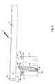
figure 1 is an "exploded" wiev of the superior hinge, with double arm, making part of the couple of hinge of the present invention; - the
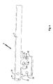
figure 2 is always an "exploded" wiev, but of the inferior hinge that results a little different respect to the superior hinge, but always making part of the present invention; - the
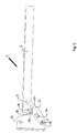
figure 3 is a "plant" wiev of the superior hinge in the closed position ; - the
figure 4 is a "plant" wiev of the inferior hinge in the closed position as the hinge offigure 3 - the
figure 5 is a "plant" wiev of the superior hinge in the open position with a right-angle; - the
figure 6 is a "plant" wiev of the inferior hinge in the open position with a right angle; - the
figure 7 is a "plant" wiev of the superior hinge in the open position with a blunt angle i.e, nore than a right angle; - the
figure 8 is a "plant" wiev of the inferior hinge in the open position with a blunt angleas the hinge offigure 7 ; - the
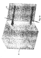
figure 9 shows a pospective wiev of the superior and inferior hinges applied closed to a possible element refrigerator cell-door that is in evidence with a thin line and fullfilled with many little spots; - the
figure 10 shows always with a perspective wiev of the superior and inferior hinges applied opened with a right angle of opening to a possible element refrigerator cell-door that is in evidence with a thin line and fullfilled with many little spots; - the
figure 11 in the end shows always with a perspective wiev of the superior and inferior hinges applied opened with a blunt angle of opening to a possible element refrigerator cell-door that is in evidence with a thin line and fullfilled with many little spots; - Is placed in evidence that the common particulars will be identified with the same references, futhermore some particulars are presents in both inges and then they'll have the same reference in the respective figures that edvidences them.
- With a particular reference to the
figure 1 it will be noted that thesuperior hinge 1 will be constituted by anarm 11 with a "C" section profile to fix the same to the door of the refrigerator. Thisarm 11 will be provided of holes F which will go to engages with some pins P1 and P2 (the pins P1 resulting longer than pins P2) with a conformation as a "head" that will be preferably rivet to fix with it. Nothing forbid to apply, in sobstitution of the rivet, other equivalent might to lock of the pins P1 and P2 having a conformation as a "head" (split pins, sieger rings, etc.) to fix them to the various parcticoulars of the hinge. Always with reference tofigure 1 it wil be noted that the twosmall arms small arm 12 will have a rounded conformation as an hook which sunked part of it will 12a will have an remarkable importance in the phase of opening of the door with a blunt angle. Saidsmall arm 12 will be futrhermore provided at his extremity of two holes Fb for the accomodation of idoneous bushes B inside which will engage the pins P1 and P2. Inferioursly to thesmall arm 12 will be placed thesmall arm 13 shaped as a "λ" with asunked part 13a that permits the opening with a blunt angle to the door. Inferioursly to thesmall arm 12 will be furthermore provided of a spacer D, but previous interposition of a washer R, that in the maximum opening of the door, i.e. with a blunt angle, it will works as a stop for the opening going to thesunked part 13a of the inferiorsmall arm 13. Inferioursly to saidelements arm 11 andsmall arms small arms arm 11 of fixing to the door PO, some washer R in the function of anti-friction agents. Furthermore said hinge constituted throught the above mentioned elements will have also a recall spring M that will go to engages by his rings M1 and M2 with the hooking screw of anchorage V1 and V2 that respectively them result to engage by screwing, the longer V1 into the hole F1 of theplate 1 provided of a screw nut D for the unamovable fixing of said screw V1, while the second V2 will engage by screwing in the threaded hole F2 in the zone corresponding to the rear arm of the "λ" of the small arm just shaped as a "λ". - Clearly the above mentioned parcticoulars, so as described, will be joint between them to obtain the hinge with double superior arm that will operates as an hinge of recall because provided of a recall spiring M.
- Parcticular attention will be placed to the
figure 2 in which it results in evidence the exploded wiev of theinferior hinge 2. Saidinferior hinge 2 will be constituted, as for the superior 1, by anarm 11 of fixing to the door PO, with a "C" shaped section, it is provided of holes F i which will go to engages some pins P1and P2 shaped as "head" that will be preferably rivet to fix it to thecomplete hinge 2. - Always referring to
figure 2 it will be noted that the twosmall arms small arm 22 will have it too, as the 12 a rounded conformation as an hook which has asunked part 22a which will have a remarkable importance in the opening phase of the door with a blunt angle. Saidsmall arm 22 will be furthermore provided at his extremity of holes Fb for the housing of idoneous bushes B in which will engages the pins P1 and P2. Furthermore on his (22) superior surface, in an idoneous zone will be obtained a "slot" C for the housing of the needle Ru. Superiorsly to thesmall arm 22 will be placed thesmall arm 23 shaped as a "bisquit" with a sunken part 32a to permit the opening of the door with a blunt angle. Inferioursly to thesmall arm 23 wil be furthermore provided a "slot" C that is identical for shape and dimensions to the "slot" C of thesmall arm 22 and placed into an idoneous zone of saidsmall arm 23. In saidhinge 2 will be provided, as in thehinge 1, a spacer D that in the maximum opening of the door, i.e. with a blunt angle, it will works as a stop for the opening going to impact against to thesunken part 23a of the superiorsmall arm 23. Inferioursly to saidelements fixing arm 11 to the door of the washer R having anti-friction function. Clearly the above mentioned particulars, so as described, will be joint between them to obtain an inferiour double arm hinge that will works as a holder and bearing hinge with his needles Ru that moves on the orizontal surfaces of the plate A1. Also thehinge 2 will engage with his plate A1, by knewn systems and then because of this not described, placed into holes or engagement might knewn obtained on said plate A1. - It is to relevate that it has not been a longer and detailed description of the singles particulars because the particulars are doing a function knew and then not important at the end of this invention. To the end to describe the fundamental object of the present invention and understand as it works it has been done references tothe figures from3 to 11.
- With a parcticoular reference to the
figures 3 ,5 and7 referred to thesuperior hinge 1 it will be remarked that the three points of placement of it (1), that can be defined as "fundamental positions" and also as will be moved the various parcticoulars that constitute it, while saidsuperior hinge 1 passes from the closed position offigure 3 to the open position offigure 5 with a right angle and after infigure 7 with a blunt angle. Are not described the passages and the positions of the singles particulars because are clear and evident. It is placed in edvidence only that in the three positions of thefigures 3 ,5 and7 the spring M hooked with the anchorage screws V1 and V2, with his rings M1 and M2, will goes to charges and then will be placed in a recall closing "tension" of the door P against the cell C to which (1) is applied (as consequently shown in the above mentioned figures), saidhinge 1. The three positions will shown, as above mentioned, furthermore than the moving of thesmall arms figure 7 . - With reference to the
figures 4 ,6 and8 it can be remarked that as for thesuperior hinge 1, theinferior hinge 2 that passes it also by the three above mentioned positions and is in evidence as thesmall arms - Precisely, the needle Ru, of the
small arm 23, placed into the slot C realized in his (23) inferior face, in the opening movement of thehinge 2, it will hold the weight that is acting on it (Ru) and due to the weight of the door of the refrigerator cell, downloading said weight on the shaped plate A1, while the second needle Ru inserted in the slot C, obtained on the superior face of thesmall arm 22, will works as an element of guide and a stabilization to the vertical solicitations that could happens more than to the force of the weight of the door P of the refrigeration cell CF. - Concluding, the needles Ru, inserted in the slots C of the
small arms - Is to point the attention that the particolular conformation which has been done reference could be changed without perhaps to go out from the constructive and functional field of this above mentioned invention.
- Is to add to this that the couple of hinges so as described can be applied to several solutions of utilization and in furnishing fields, as for example the utilization as hinges for wardrobes/cupboards doors, or other furnitures to them applicable.
- Well is comprised that this and other veriatiion of the matter of the invention could be applied without perhaps going out from the field of how above described and consequently claimed and then from the dominion of the present invention
Claims (1)
- Improved couple of hinge particoularly applied to refrigerators constituted by respetive plates (A) and (A1) engaging on the body of the refrigeration cell (FC) on which (A-A1) are engaged by pins (P1-P2) respective small arms (12-13 and 22-23) that are connected to the arms (11) always by the pins (P1 and P2) going them (11) to engage with the door (P) of closure of the refrigeration cell (CF) charaterized by the fact that at least one of the two small arms (22-23) of the hinge (2) has on a preferred zone a slot (C) for the housing of the needle (Ru) that will have the function of an element of resistence and holding, of the hinge (2), to the vertical sollicitations generally and particoularly to that due to the weight of the door (P), leaning and moving in sliding by rotation on the face of the plate (A1) to it (Ru) corresponding.
Applications Claiming Priority (1)
| Application Number | Priority Date | Filing Date | Title |
|---|---|---|---|
| ITPN20060036 ITPN20060036A1 (en) | 2006-05-12 | 2006-05-12 | "PAIR OF FIXED TYPE HINGES PARTICULARLY APPLICABLE TO REFRIGERATED CELLS" |
Publications (1)
| Publication Number | Publication Date |
|---|---|
| EP2131124A2 true EP2131124A2 (en) | 2009-12-09 |
Family
ID=40258591
Family Applications (1)
| Application Number | Title | Priority Date | Filing Date |
|---|---|---|---|
| EP20070009544 Withdrawn EP2131124A2 (en) | 2006-05-12 | 2007-05-11 | Improved couple of hinge particularly applied to refrigerators |
Country Status (2)
| Country | Link |
|---|---|
| EP (1) | EP2131124A2 (en) |
| IT (1) | ITPN20060036A1 (en) |
Cited By (1)
| Publication number | Priority date | Publication date | Assignee | Title |
|---|---|---|---|---|
| US8572808B2 (en) * | 2012-02-23 | 2013-11-05 | Sub-Zero, Inc. | Controlled closure system for a hinge |
-
2006
- 2006-05-12 IT ITPN20060036 patent/ITPN20060036A1/en unknown
-
2007
- 2007-05-11 EP EP20070009544 patent/EP2131124A2/en not_active Withdrawn
Cited By (3)
| Publication number | Priority date | Publication date | Assignee | Title |
|---|---|---|---|---|
| US8572808B2 (en) * | 2012-02-23 | 2013-11-05 | Sub-Zero, Inc. | Controlled closure system for a hinge |
| US8844097B2 (en) | 2012-02-23 | 2014-09-30 | Sub-Zero, Inc. | Soft opening for a hinge |
| US9228384B2 (en) | 2012-02-23 | 2016-01-05 | Sub-Zero, Inc. | Hinge mounted switch control device |
Also Published As
| Publication number | Publication date |
|---|---|
| ITPN20060036A1 (en) | 2007-11-13 |
Similar Documents
| Publication | Publication Date | Title |
|---|---|---|
| AU2020102918B4 (en) | Hinge | |
| US3748688A (en) | Self-closing door hinges | |
| US20040226139A1 (en) | Hinge with spring for furniture | |
| US20120210540A1 (en) | Door actuator | |
| US9771741B2 (en) | Dual cam lock apparatus | |
| CN114382341A (en) | Door and window handle without decorative cover | |
| KR200410197Y1 (en) | Door hinge with damper | |
| EP2131124A2 (en) | Improved couple of hinge particularly applied to refrigerators | |
| EP3612699B1 (en) | Mechanism for moving a furniture door | |
| EP2886762B1 (en) | Multi-link hinge | |
| US10550607B2 (en) | Latch assembly for a sliding door | |
| CN111577044B (en) | Upturning random stop lifting and damping closing device | |
| KR20070007051A (en) | Furniture hinges with spring | |
| EP2484851A1 (en) | An ambidextrous mortise door lock | |
| KR102130065B1 (en) | A hinges of furniture | |
| US1344508A (en) | Antirattle-catch | |
| CN219808837U (en) | Door lock structure for refrigeration equipment and refrigeration equipment | |
| AU2017100333B4 (en) | Hinge | |
| AU2021107565A4 (en) | Hinge | |
| CN220504816U (en) | Adjustable hinge and door assembly and window assembly comprising same | |
| CA3060852C (en) | Mechanism for moving a furniture door | |
| CN205936140U (en) | Spring safe that opens door | |
| WO2022195359A1 (en) | A lock assembly for a sliding door | |
| GB2494281A (en) | Hinge with positional control | |
| NZ734788B2 (en) | A latch assembly for a sliding door |
Legal Events
| Date | Code | Title | Description |
|---|---|---|---|
| PUAJ | Public notification under rule 129 epc |
Free format text: ORIGINAL CODE: 0009425 |
|
| PUAI | Public reference made under article 153(3) epc to a published international application that has entered the european phase |
Free format text: ORIGINAL CODE: 0009012 |
|
| AK | Designated contracting states |
Kind code of ref document: A2 Designated state(s): AT BE BG CH CY CZ DE DK EE ES FI FR GB GR HU IE IS IT LI LT LU LV MC MT NL PL PT RO SE SI SK TR |
|
| AX | Request for extension of the european patent |
Extension state: AL BA HR MK RS |
|
| STAA | Information on the status of an ep patent application or granted ep patent |
Free format text: STATUS: THE APPLICATION IS DEEMED TO BE WITHDRAWN |
|
| 18D | Application deemed to be withdrawn |
Effective date: 20100105 |