EP2131038A2 - System und Verfahren zur Erfassung von Auslösungsereignisdaten und Windturbine damit - Google Patents
System und Verfahren zur Erfassung von Auslösungsereignisdaten und Windturbine damit Download PDFInfo
- Publication number
- EP2131038A2 EP2131038A2 EP09161445A EP09161445A EP2131038A2 EP 2131038 A2 EP2131038 A2 EP 2131038A2 EP 09161445 A EP09161445 A EP 09161445A EP 09161445 A EP09161445 A EP 09161445A EP 2131038 A2 EP2131038 A2 EP 2131038A2
- Authority
- EP
- European Patent Office
- Prior art keywords
- data
- trip
- operational data
- wind turbine
- trip event
- Prior art date
- Legal status (The legal status is an assumption and is not a legal conclusion. Google has not performed a legal analysis and makes no representation as to the accuracy of the status listed.)
- Granted
Links
- 238000000034 method Methods 0.000 title abstract description 22
- 239000000872 buffer Substances 0.000 claims abstract description 80
- 238000001514 detection method Methods 0.000 claims abstract description 10
- 230000000717 retained effect Effects 0.000 claims description 4
- 239000011295 pitch Substances 0.000 description 22
- 238000013480 data collection Methods 0.000 description 10
- 230000006870 function Effects 0.000 description 10
- 238000004891 communication Methods 0.000 description 7
- 238000012544 monitoring process Methods 0.000 description 6
- 238000005070 sampling Methods 0.000 description 6
- 238000006073 displacement reaction Methods 0.000 description 4
- 238000012546 transfer Methods 0.000 description 3
- 238000013481 data capture Methods 0.000 description 2
- 238000010586 diagram Methods 0.000 description 2
- 230000000694 effects Effects 0.000 description 2
- 230000005611 electricity Effects 0.000 description 2
- 230000007613 environmental effect Effects 0.000 description 2
- 239000005431 greenhouse gas Substances 0.000 description 2
- 230000006698 induction Effects 0.000 description 2
- 230000008569 process Effects 0.000 description 2
- 230000003068 static effect Effects 0.000 description 2
- 230000008901 benefit Effects 0.000 description 1
- 230000033228 biological regulation Effects 0.000 description 1
- 238000006243 chemical reaction Methods 0.000 description 1
- 238000010924 continuous production Methods 0.000 description 1
- 230000008878 coupling Effects 0.000 description 1
- 238000010168 coupling process Methods 0.000 description 1
- 238000005859 coupling reaction Methods 0.000 description 1
- 238000013500 data storage Methods 0.000 description 1
- 230000009977 dual effect Effects 0.000 description 1
- 210000003746 feather Anatomy 0.000 description 1
- 230000007246 mechanism Effects 0.000 description 1
- 238000012986 modification Methods 0.000 description 1
- 230000004048 modification Effects 0.000 description 1
- 230000005405 multipole Effects 0.000 description 1
- 230000003287 optical effect Effects 0.000 description 1
- 238000012545 processing Methods 0.000 description 1
- 230000001052 transient effect Effects 0.000 description 1
Images
Classifications
-
- F—MECHANICAL ENGINEERING; LIGHTING; HEATING; WEAPONS; BLASTING
- F03—MACHINES OR ENGINES FOR LIQUIDS; WIND, SPRING, OR WEIGHT MOTORS; PRODUCING MECHANICAL POWER OR A REACTIVE PROPULSIVE THRUST, NOT OTHERWISE PROVIDED FOR
- F03D—WIND MOTORS
- F03D7/00—Controlling wind motors
- F03D7/02—Controlling wind motors the wind motors having rotation axis substantially parallel to the air flow entering the rotor
- F03D7/04—Automatic control; Regulation
- F03D7/042—Automatic control; Regulation by means of an electrical or electronic controller
- F03D7/047—Automatic control; Regulation by means of an electrical or electronic controller characterised by the controller architecture, e.g. multiple processors or data communications
-
- F—MECHANICAL ENGINEERING; LIGHTING; HEATING; WEAPONS; BLASTING
- F03—MACHINES OR ENGINES FOR LIQUIDS; WIND, SPRING, OR WEIGHT MOTORS; PRODUCING MECHANICAL POWER OR A REACTIVE PROPULSIVE THRUST, NOT OTHERWISE PROVIDED FOR
- F03D—WIND MOTORS
- F03D17/00—Monitoring or testing of wind motors, e.g. diagnostics
-
- F—MECHANICAL ENGINEERING; LIGHTING; HEATING; WEAPONS; BLASTING
- F03—MACHINES OR ENGINES FOR LIQUIDS; WIND, SPRING, OR WEIGHT MOTORS; PRODUCING MECHANICAL POWER OR A REACTIVE PROPULSIVE THRUST, NOT OTHERWISE PROVIDED FOR
- F03D—WIND MOTORS
- F03D7/00—Controlling wind motors
- F03D7/02—Controlling wind motors the wind motors having rotation axis substantially parallel to the air flow entering the rotor
- F03D7/022—Adjusting aerodynamic properties of the blades
- F03D7/0224—Adjusting blade pitch
-
- F—MECHANICAL ENGINEERING; LIGHTING; HEATING; WEAPONS; BLASTING
- F05—INDEXING SCHEMES RELATING TO ENGINES OR PUMPS IN VARIOUS SUBCLASSES OF CLASSES F01-F04
- F05B—INDEXING SCHEME RELATING TO WIND, SPRING, WEIGHT, INERTIA OR LIKE MOTORS, TO MACHINES OR ENGINES FOR LIQUIDS COVERED BY SUBCLASSES F03B, F03D AND F03G
- F05B2270/00—Control
- F05B2270/30—Control parameters, e.g. input parameters
- F05B2270/328—Blade pitch angle
-
- F—MECHANICAL ENGINEERING; LIGHTING; HEATING; WEAPONS; BLASTING
- F05—INDEXING SCHEMES RELATING TO ENGINES OR PUMPS IN VARIOUS SUBCLASSES OF CLASSES F01-F04
- F05B—INDEXING SCHEME RELATING TO WIND, SPRING, WEIGHT, INERTIA OR LIKE MOTORS, TO MACHINES OR ENGINES FOR LIQUIDS COVERED BY SUBCLASSES F03B, F03D AND F03G
- F05B2270/00—Control
- F05B2270/30—Control parameters, e.g. input parameters
- F05B2270/335—Output power or torque
-
- G—PHYSICS
- G05—CONTROLLING; REGULATING
- G05B—CONTROL OR REGULATING SYSTEMS IN GENERAL; FUNCTIONAL ELEMENTS OF SUCH SYSTEMS; MONITORING OR TESTING ARRANGEMENTS FOR SUCH SYSTEMS OR ELEMENTS
- G05B2219/00—Program-control systems
- G05B2219/20—Pc systems
- G05B2219/26—Pc applications
- G05B2219/2619—Wind turbines
-
- Y—GENERAL TAGGING OF NEW TECHNOLOGICAL DEVELOPMENTS; GENERAL TAGGING OF CROSS-SECTIONAL TECHNOLOGIES SPANNING OVER SEVERAL SECTIONS OF THE IPC; TECHNICAL SUBJECTS COVERED BY FORMER USPC CROSS-REFERENCE ART COLLECTIONS [XRACs] AND DIGESTS
- Y02—TECHNOLOGIES OR APPLICATIONS FOR MITIGATION OR ADAPTATION AGAINST CLIMATE CHANGE
- Y02E—REDUCTION OF GREENHOUSE GAS [GHG] EMISSIONS, RELATED TO ENERGY GENERATION, TRANSMISSION OR DISTRIBUTION
- Y02E10/00—Energy generation through renewable energy sources
- Y02E10/70—Wind energy
- Y02E10/72—Wind turbines with rotation axis in wind direction
Definitions
- This invention relates generally to wind turbines, and more particularly, to a system and method for acquiring trip event data in wind turbines.
- wind turbines use the wind to generate electricity.
- the wind turns one or more blades connected to a hub, where the blades and hub can comprise a rotor.
- the spin of the blades caused by the wind spins a shaft connected to the rotor, which connects to a generator that generates electricity.
- the rotor is mounted within a housing or nacelle, which is positioned on top of a truss or tubular tower.
- Utility grade wind turbines e.g., wind turbines designed to provide electrical power to a utility grid
- Blades on these rotors transform wind energy into a rotational torque or force that drives one or more generators, rotationally coupled to the rotor through a gearbox.
- the gearbox may be used to step up the inherently low rotational speed of the turbine rotor for the generator to efficiently convert mechanical energy to electrical energy, which is provided to a utility grid.
- Some turbines utilize generators that are directly coupled to the rotor without using a gearbox.
- Power converters are used to transfer the power from the generator to a grid connection.
- a required level of energy will pass through a DC link of the power converter.
- high power mismatch between the rotor and the grid connection temporally exist and voltage transients become amplified such that a DC link voltage level can increase above normal allowed or rated levels.
- wind turbines have to be able to absorb or deflect the excessive power level.
- Pitch control subsystems are used to rotate the blades about their axial or longitudinal axis.
- an electronic controller is used in conjunction with a blade pitch mechanism to pitch the blades around their respective longitudinal axes to control the power output of the wind turbine.
- Motors can be provided to pitch the blades while the rotor is turning.
- the pitch control subsystem can also be used to feather the blades during storm conditions.
- Wind turbine controllers can be used to monitor many operating parameters of the wind turbine, and various environmental conditions (e.g., wind speed, ambient temperature, etc.). In addition, the wind turbine controller can instruct the various wind turbine subsystems to adjust various operating modes to compensate for or react to changing environmental conditions.
- various environmental conditions e.g., wind speed, ambient temperature, etc.
- wind turbines comprise three subsystems, the pitch control subsystem, the power converter subsystem and the wind turbine controller subsystem. Sensor data from each of these subsystems can be helpful in determining when and why a fault or trip event occurred. To date, no single system has provided a means for obtaining and consolidating relevant data from each of the three subsystems listed above.
- a system for acquiring operational data from a wind turbine and analyzing trip events.
- One or more data buffers can store operational data obtained from at least one control subsystem.
- a trip event detection system can be connected to the data buffers, and monitors for the occurrence of a trip event.
- the data stored in the data buffers can be transferred to a trip log buffer.
- a method for acquiring operational data from a wind turbine and analyzing trip events. The method comprises the steps of: obtaining operational data from at least one control subsystem, storing operational data in one or more data buffers, monitoring the operational data for the indication of a trip event, and upon the indication of a trip event, transferring all or a subset of the operational data contained within the data buffers to a trip log buffer.
- Various embodiments of the present invention include a system and method for acquiring and analyzing operational data obtained from a wind turbine.
- Various technical effects of various embodiments include acquiring operational data from one or more subsystems of the wind turbine.
- Other technical effects include monitoring and analyzing the operational data to determine if a trip event occurred, when a trip event occurred and why the trip event occurred.
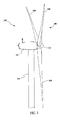
- a wind turbine system includes one or more wind turbines 100.
- the wind turbines 100 generally include a nacelle 102 housing a generator (not shown in Figure 1 ).
- the nacelle 102 can be mounted on a tower 104, only a portion of the tower 104 being shown in Figure 1 .
- the wind turbine 100 also includes a rotor 106 that includes a plurality of rotor blades 108 attached to a rotating hub 110.
- the wind turbine 100 illustrated in Figure 1 includes three rotor blades 108, there are no specific limits on the number of rotor blades 108 required by various embodiments of the present invention. Thus, additional or fewer rotor blades 108 may be provided.
- various components are housed in the nacelle 102 on the tower 104 of the wind turbine 100. Further, the height of the tower 104 may be selected based upon factors and conditions known in the art.
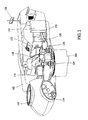
- one or more microcontrollers within a control panel 112 form a control system (described in more detail below) used for overall system monitoring and control including pitch and speed regulation, high-speed shaft and yaw brake application, yaw and pump motor application, and power level and fault monitoring.
- Alternative distributed or centralized control architectures may be used in some embodiments.
- control system provides control signals to a variable blade pitch drive 114 to control the pitch of blades 108 (shown in Figure 1 ) that drive hub 110 as a result of wind.
- An electric motor with drive can be used to pitch the blades, or hydraulics could be used for pitch control of blades.
- the control system also provides control signals to a converter of a conversion component as described in more detail below.
- the hub 110 receives three blades 108, but other configurations can utilize any number of blades.
- the pitches of the blades 108 are individually controlled by the blade pitch drive 114.
- the hub 110 and blades 108 together form the wind turbine rotor 106.
- the drive train of the wind turbine includes a main rotor shaft 116 (also referred to as a "low speed shaft") connected to the hub 110 and a gear box 118 that, in some embodiments, utilizes a dual path geometry to drive a high speed shaft enclosed within the gear box 118.
- the high speed shaft (not shown in Figure 2 ) is used to drive a generator 120 that is supported by a main frame 132.
- rotor torque is transmitted via a coupling 122.
- the generator 120 may be of any suitable type, for example and without limitation, a wound rotor induction generator, such as a doubly fed induction generator.
- a wound rotor induction generator such as a doubly fed induction generator.
- Another suitable type by way of non-limiting example is a multi-pole generator that can operate at the speed of the low speed shaft in a direct drive configuration, without requiring a gearbox.
- a yaw drive 124 and a yaw deck 126 provide a yaw orientation system for the wind turbine 100.
- the yaw orientation system is electrically operated and controlled by the control system in accordance with information received from sensors used to measure shaft flange displacement, as described below. Either alternately or in addition to the flange displacement measuring sensors, some configurations utilize a wind vane 128 or other type of anemometer to provide information for the yaw orientation system.
- the yaw system is mounted on a flange provided atop tower 104.
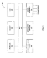
- a control system 300 for the wind turbine 100 includes a bus 302 or other communication device to communicate information.
- Processor(s) 304 are coupled to the bus 302 to process information, including information from a variety of sensors configured to measure various operational data, such as, power levels, power fluctuations, displacements, moments, vibration levels, pitch related data, power converter data, and other operating conditions.
- the control system 300 further includes random access memory (RAM) 306 and operational data buffer 308.
- the RAM 306 is coupled to the bus 302 to store and transfer information and instructions to be executed by the processor(s) 304.
- the RAM 306 also can be used to store temporary variables or other intermediate information during execution of instructions by the processor(s) 304.
- the operational data buffer 308 can comprise one or more memory devices, and is used to store operational data received from the variety of sensors connected to the various subsystems and components of wind turbine 100.
- the operational data buffer 308 is comprised of one or more non-volatile memory devices, however, volatile memory could be used as well.
- the control system 300 can also include read only memory (ROM) and or another static storage device 310, which is coupled to the bus 302 to store and provide static (i.e., non-changing) information and instructions to the processor(s) 304.
- ROM read only memory
- static storage device 310 which is coupled to the bus 302 to store and provide static (i.e., non-changing) information and instructions to the processor(s) 304.
- Input/output device(s) 312 may be provided and can include any device known in the art to provide input data to or output data from the control system 300.
- output devices 312 could be wireless transmitters, fiber-optic or cable based communication cables, Internet or packet based communications, or any other suitable communication method.
- Instructions are provided to memory from a storage device, such as magnetic disk, a read-only memory (ROM) integrated circuit, CD-ROM, DVD, via a remote connection that is either wired or wireless and that provides access to one or more electronically-accessible media, etc.
- a storage device such as magnetic disk, a read-only memory (ROM) integrated circuit, CD-ROM, DVD, via a remote connection that is either wired or wireless and that provides access to one or more electronically-accessible media, etc.
- ROM read-only memory
- DVD digital versatile discs
- ROM read-only memory
- hard-wired circuitry can be used in place of or in combination with software instructions.
- execution of sequences of instructions is not limited to any specific combination of hardware circuitry and software instructions.
- the sensor interface 314 is an interface that allows control system 300 to communicate with one or more sensors.
- the sensor interface 314 can be or can include, for example, one or more analog-to-digital converters that convert analog signals into digital signals that can be used by processor(s) 304.
- These sensors can sense, for example, various operational data, such as, power levels, power fluctuations, displacements, moments, vibration levels, pitch related data, power converter data, and other operating conditions within the wind turbine 100.
- a system and method for acquiring operational data from various sub-systems of wind turbine 100.
- high fidelity relevant data is needed.
- these sub-systems may include, but are not limited to, the pitch control sub-system, power converter subsystem, wind turbine controller sub-system, and yaw drive subsystem.
- high-resolution operational data is obtained from one or more sub-systems in a continuous process.
- data can be obtained at the frame rate or rate of the control logic sweep time, which may be about one sample per 10 ms to about 40 ms.
- the sampling rate for operational data, of any sub-system should be at a sufficiently high rate to obtain high resolution and high quality data, and this rate may include rates above or below the 10 ms to 40 ms range described previously.
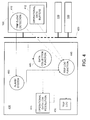
- Fig. 4 illustrates one exemplary embodiment of the present invention.
- Multiple wind turbines 100 can comprise a wind farm, and each wind turbine 100 may be connected to a communication network 420.
- Network 420 can be wired (e.g., Ethernet TM a trademark of the Xerox Corporation, fiber-optic cables, telephone wires, IEEE 802.3, etc.) or wireless (e.g., WiFi® a registered trademark of the Wi-Fi Alliance, WiMAX TM a trademark of the WiMAX Forum, radio frequency, IEEE 802.11 standard, etc.).
- a workstation 430 may be connected to network 420 and/or to each wind turbine 420. The workstation collects and stores the operational data received from the wind turbines 100.
- the workstation 430 can be a local device within the wind farm, or it can be remotely located.
- Each wind turbine 100 can include a control system 300 that may comprise a trip event detection function 410 and one or more operational data buffers 412.
- the control system may be present within each wind turbine 100 of a wind farm.
- the trip event detection function 410 monitors for predetermined criteria that may indicate a trip event has occurred or for indicators that a trip event may occur.
- Operational data from one or more sub-systems of wind turbine 100 are stored within operational data buffers 412.
- the operational data buffers can comprise one or more storage devices and are preferably non-volatile storage media (e.g., flash memory, optical or magnetic storage media, etc.).
- Operational data can be acquired at a high resolution (e.g. one sample every 10 ms to 40 ms) from a variety of sensors in multiple sub-systems of wind turbine 100.
- Trip event detection module 410 monitors for predetermined criteria that may indicate a trip event. If a trip event has occurred, the data stored within operational data buffers 412 can be transferred to the workstation 430. In one embodiment, data before and after the trip event can be stored and transferred to workstation 430. In other embodiments, data up to and/or prior to the trip event may be transferred to workstation 430. For analysis of the trip event, the resolution of data sampling can vary based on how far in time the data is from the event.
- the data may be grouped in varying data resolutions based on the time relative to the trip event. For example, data after the trip event may be sent to workstation 430 at a rate of one sample per one second. This post trip data may comprise an interval of one to thirty minutes or more after the trip event.
- Pre-trip data may be grouped into about four or more time periods. However, pre-trip data could also be grouped into less than four time periods depending on the application. Data which is prior to the trip event (i.e., pre-trip) by 20 minutes or less may be re-sampled at a one sample per one second rate. Data which is prior to the trip event by about 20 minutes to about 60 minutes may be re-sampled at a one sample per ten second rate. Data which is prior to the trip event by about one hour to about five hours may be re-sampled at a one sample per one minute rate.
- Data which is prior to the trip event by about five hours to about 24 hours may be re-sampled at a one sample per ten minute rate.
- the data may be re-sampled at varying resolutions based on predetermined time intervals. Tables 1 and 2 illustrate two examples of the data resolutions that can be assigned to time periods surrounding a trip event.
- TABLE 1 Post-Trip Data Pre-Trip Data Time From 0 to 0 to -20 min. to -1 hour to -5 hours to Trip Event +30 min. -20 min. -60 min. -5 hours -24 hours Sample 1 sample 1 sample 1 sample 1 sample 1 sample 1 sample 1 sample Rate per sec. per sec. per 10 sec. per 60 sec. per 10 min.
- Table 1 illustrates one example of varying resolution data capture and/or storage.
- a " + " in the table indicates a post-trip event time period (i.e., after the trip event), and a " - " indicates a pre-trip time period (i.e., before the trip event).
- any range and number of time periods and data resolution/sample rates can be employed as required by the specific application. The ranges specified above are only examples of many suitable time periods and sample rates.
- Operational data can be transferred from a wind turbine 100 to workstation 430 before, during or after a trip event.
- a trip log function 440 and the data collection function 445 comprise a data collection system and receive operational data from wind turbines 100.
- Data at varying resolutions can be stored within trip log 450.
- the trip log 450 stores data that is within 24 hours of the trip event. Longer term data, data which may be greater than 24 hours, may be stored in operational data low resolution data store 455. Data may be retained within low-resolution data store 455 at any suitable sampling rate, but is normally at the fastest of the lower resolution data stored within trip log 450.
- data may be stored within trip log 450 according to the time periods and sampling rates identified in Table 1.
- Data stored in the operational data low-resolution data store 455 could be retained at a rate of one sample per second.
- data within 24 to 48 hours or more from the current time can be stored within data store 455, and in other embodiments data within 1 day to 1 week or more may be stored within data store 455. Only a few examples have been given, but any suitable data resolution and/or time period(s) may be implemented as dictated by the specific application.
- TABLE 2 Post-Trip Data Pre-Trip Data Time From 0 to 0 to -1 to -20 min. to -1 hour to -5 hours to Trip Event +30 sec. -1 min. -20 min. -60 min.
- Table 2 illustrates another example of sampling rates and time periods that may be used in various aspects of the present invention.
- the post trip data is grouped into one time period, and the pre-trip data is grouped into five time periods.
- the sampling rates for each time period are shown in Table 2.
- the data source is also indicated, with the operational data buffers 308, 412 supplying the post-trip data and the pre-trip data less than about 1 minute from the trip.
- the operational data low resolution data store 455 can supply pre-trip data that is more than one minute prior to the trip event.
- the ranges specified above are only examples of many suitable time periods and sample rates. However, any range and number of time periods and data resolution/sample rates can be employed as required by the specific application.
- alarm events can be included in the trip log.
- An alarm system 460 can be used in conjunction with the trip log function.
- Wind turbines 100 can be configured to issue alarms if predetermined conditions occur or specific operating ranges are exceeded.
- the wind turbine alarms can be received by alarm system 460 within workstation 430, and may trigger the data capture and/or transfer process.
- control device may be comprised of trip event detection function 410 and operational data buffer(s) 412, and may reside within each wind turbine 100.
- the application code in the control device determines the conditions that constitute a trip and monitors for those conditions.
- the data buffers 412 can collect data for the specified variables at high resolution (e.g., the frame rate, rate at which the controller is running, or the rate of the control logic sweep time, generally between about 10 to 40 milliseconds).
- the number of data buffers used is configurable and is determined by the application.
- a first portion of the data buffers could be assigned to specific faults (e.g., pitch related trip events), and a second portion of the data buffers could be assigned to a different type of trip event (e.g., power converter faults.
- the data buffers 412 may take as input a trigger, number of samples per trigger, number of samples post trigger and the variables (data points) to be collected.
- the block outputs a status signal that indicates the state of the capture block.
- the capture block will have a status of waiting for trigger and be collecting data for the pre-trigger samples.
- a trip event occurs the block status changes to capturing and data is collected for the number of post-trigger samples.
- the control device may also be connected to the network 420 and is capable of sending and receiving data across the network.
- an ad hoc network may be created or point-to-point data communication can be implemented.
- the variables being collected in the data buffers 412 is part of the data that the controller sends across the network.
- the workstation 430 may be a personal computer or laptop computer running the Microsoft Windows TM operating system. However, any suitable processing means and operating system can be used.
- the workstation can be loaded with a software product that may contain several sub-systems. One of those sub-systems can be a data collection sub-system (elements 440 and 445). When the data collection is configured for a trip log it can have multiple functions.
- a first function can be to collect and store the data values of the variables defined in the trip. These are the same variables being collected in the data buffers 412. The difference is that the data collection gets the values from the data the control device sends across the network. The data collection can store this data at a one second rate (or multiple rates or other rates) into files or a database located in or accessible to the workstation 430.
- the data collection sub-system 440 and 445
- a second function of the data collection can be to monitor the status values on the data buffers 412. When these buffers go to a complete state then the data collection function 445 knows a trip event has occurred and that the data from the data buffers 412 is available to be transferred to the workstation 430.
- the data collection system (440 and 445) can create a file (e.g., trip log 450) that contains re-sampled data from the operational data low resolution data store 455, and data obtained from the operational data buffers 412.
- the data resolution can be higher near the trip event and progressively becomes lower as time progresses further from the trip event.
- Another piece of information that can be written to the trip log is the alarms/events that occurred around the time of the trip event. This information can be obtained from the alarm system 460 that is part of the software in the workstation 430.
- the alarm system 460 obtains the alarms from the control device and keeps a historical copy.
- the data file obtained by the workstation 430 can be viewed using a variety of software products (e.g., a Trender*, which is part of the ToolboxST* and/or WorkstationST* software products, where a "*" denotes Trademarks of the General Electric Company).
- the WorkstationST* software product can also provide the ability to convert the file into a Comma Separated Variable (.csv) file which may then be opened by other third party products, such as common spreadsheet programs, for root cause analysis.
- a Comma Separated Variable (.csv) file which may then be opened by other third party products, such as common spreadsheet programs, for root cause analysis.
- Another advantage is that all the data can be contained in one file and the single file can be transferred from a remote site for root cause analysis.
- the workstation 430 could be laptop based and portable. This would enable the workstation to be transported from wind farm to wind farm.
- the workstation 430 could also be located at a remote site and connected to each wind turbine over any suitable communication link (e.g., network 420 or the Internet).
- the workstation could also be a local device housed within the wind farm, either within a specific tower or within an electronics center.
- Operational data can be transferred from the wind turbine 100 or workstation 430 at one or more sample rates to a data file, database or trip log before, during or after a trip event.
Landscapes
- Engineering & Computer Science (AREA)
- Life Sciences & Earth Sciences (AREA)
- Sustainable Development (AREA)
- Sustainable Energy (AREA)
- Chemical & Material Sciences (AREA)
- Combustion & Propulsion (AREA)
- Mechanical Engineering (AREA)
- General Engineering & Computer Science (AREA)
- Physics & Mathematics (AREA)
- Fluid Mechanics (AREA)
- Wind Motors (AREA)
- Control Of Turbines (AREA)
Applications Claiming Priority (1)
| Application Number | Priority Date | Filing Date | Title |
|---|---|---|---|
| US12/132,274 US8230266B2 (en) | 2008-06-03 | 2008-06-03 | System and method for trip event data acquisition and wind turbine incorporating same |
Publications (3)
| Publication Number | Publication Date |
|---|---|
| EP2131038A2 true EP2131038A2 (de) | 2009-12-09 |
| EP2131038A3 EP2131038A3 (de) | 2017-05-31 |
| EP2131038B1 EP2131038B1 (de) | 2018-07-11 |
Family
ID=41090371
Family Applications (1)
| Application Number | Title | Priority Date | Filing Date |
|---|---|---|---|
| EP09161445.3A Active EP2131038B1 (de) | 2008-06-03 | 2009-05-28 | System und Verfahren zur Erfassung von Auslösungsereignisdaten und Windturbine damit |
Country Status (5)
| Country | Link |
|---|---|
| US (1) | US8230266B2 (de) |
| EP (1) | EP2131038B1 (de) |
| CN (1) | CN101598110B (de) |
| DK (1) | DK2131038T3 (de) |
| ES (1) | ES2681796T3 (de) |
Cited By (7)
| Publication number | Priority date | Publication date | Assignee | Title |
|---|---|---|---|---|
| EP2481920A1 (de) * | 2011-01-31 | 2012-08-01 | Sinovel Wind Group Co., Ltd | Windturbinengenerator sowie Parametererfassungssystem und Verfahren dazu |
| EP2535573A1 (de) * | 2010-02-12 | 2012-12-19 | Mitsubishi Heavy Industries, Ltd. | Handliches endgerät für windkraftgenerator, windkraftgenerator und windkrafterzeugungsort |
| WO2013156026A1 (en) | 2012-04-16 | 2013-10-24 | Kk-Electronic A/S | A data acquisition system and a method of acquiring data from a wind turbine |
| WO2014198725A1 (de) * | 2013-06-10 | 2014-12-18 | Wobben Properties Gmbh | Verfahren zum einspeisen elektrischer leistung in ein elektrisches versorgungsnetz |
| WO2020047098A1 (en) * | 2018-08-30 | 2020-03-05 | General Electric Company | Trip reduction tool for a wind turbine power system |
| EP3702613A1 (de) * | 2019-02-28 | 2020-09-02 | General Electric Company | System und verfahren zur vorhersage von windturbinenabschaltungen aufgrund übermässiger vibration |
| WO2022002324A1 (en) * | 2020-07-02 | 2022-01-06 | Vestas Wind Systems A/S | Data collection system and method for renewable energy power plant |
Families Citing this family (13)
| Publication number | Priority date | Publication date | Assignee | Title |
|---|---|---|---|---|
| EP1662138A4 (de) * | 2003-08-12 | 2012-09-26 | Nabtesco Corp | Untersetzungsgetriebe zur verwendung in einer windnachführungsvorrichtung für eine windenergieerzeugungsvorrichtung, und windnachführungsverfahren und -vorrichtung für eine windenergieerzeugungsvorrichtung unter verwendung des untersetzungsgetriebes |
| US8155923B2 (en) * | 2009-06-08 | 2012-04-10 | General Electric Company | System, remote device, and method for validating operation of a wind turbine |
| US8451134B2 (en) * | 2009-07-24 | 2013-05-28 | Honeywell International Inc. | Wind turbine generator fault diagnostic and prognostic device and method |
| DE102009037237A1 (de) * | 2009-08-12 | 2011-02-17 | Repower Systems Ag | Verfahren und Anordnung zur automatischen Konfigurationsparameterkontrolle bei Windenergieanlagen |
| ES2586334T3 (es) * | 2009-08-21 | 2016-10-13 | Vestas Wind Systems A/S | Sistema y método para monitorizar filtros de potencia y detectar un fallo de filtro de potencia en un generador eléctrico de turbina eólica |
| US7933744B2 (en) | 2009-08-28 | 2011-04-26 | General Electric Company | System and method for managing wind turbines and enhanced diagnostics |
| US7948103B2 (en) * | 2009-09-03 | 2011-05-24 | General Electric Company | Method and system for verifying wind turbine operation |
| US8558409B2 (en) * | 2010-07-09 | 2013-10-15 | Vestas Wind Systems A/S | High voltage switchgear power supply arrangement for a wind turbine facility |
| US20120025526A1 (en) * | 2010-07-30 | 2012-02-02 | General Electric Company | System and method for monitoring wind turbine gearbox health and performance |
| DK2463517T3 (da) * | 2010-12-08 | 2014-07-21 | Siemens Ag | Fremgangsmåde og styresystem til at reducere vibrationer af et vindenergianlæg |
| CN102418660A (zh) * | 2011-10-17 | 2012-04-18 | 王风发 | 无线传输信号系统 |
| US10385829B2 (en) * | 2016-05-11 | 2019-08-20 | General Electric Company | System and method for validating optimization of a wind farm |
| JP6503419B2 (ja) * | 2017-07-07 | 2019-04-17 | 三菱重工業株式会社 | 風力発電施設のデータ収集システム及びデータ収集方法並びに風力発電施設 |
Family Cites Families (15)
| Publication number | Priority date | Publication date | Assignee | Title |
|---|---|---|---|---|
| US4862394A (en) * | 1987-01-28 | 1989-08-29 | Dallas Instruments Incorporated | Drop height recorder |
| US5463768A (en) * | 1994-03-17 | 1995-10-31 | General Electric Company | Method and system for analyzing error logs for diagnostics |
| US6336065B1 (en) * | 1999-10-28 | 2002-01-01 | General Electric Company | Method and system for analyzing fault and snapshot operational parameter data for diagnostics of machine malfunctions |
| US6892115B2 (en) * | 2002-02-25 | 2005-05-10 | General Electric Company | Method and apparatus for optimized centralized critical control architecture for switchgear and power equipment |
| US7020802B2 (en) * | 2002-10-17 | 2006-03-28 | Sun Microsystems, Inc. | Method and apparatus for monitoring and recording computer system performance parameters |
| US6898540B2 (en) * | 2002-11-12 | 2005-05-24 | General Electric Company | System and method for displaying real-time turbine corrected output and heat rate |
| US7322794B2 (en) * | 2003-02-03 | 2008-01-29 | General Electric Company | Method and apparatus for condition-based monitoring of wind turbine components |
| US7289920B2 (en) * | 2003-06-26 | 2007-10-30 | General Electric Company | Method and apparatus for capture of grid characteristics corresponding to fluctuation events |
| US7013203B2 (en) * | 2003-10-22 | 2006-03-14 | General Electric Company | Wind turbine system control |
| ATE352057T1 (de) * | 2003-11-14 | 2007-02-15 | Gamesa Eolica S A Soc Uniperso | Überwachungs- und datenverarbeitungseinheit für windräder und system für eine vorbeugende wartung für windräderanlagen |
| US6973396B1 (en) * | 2004-05-28 | 2005-12-06 | General Electric Company | Method for developing a unified quality assessment and providing an automated fault diagnostic tool for turbine machine systems and the like |
| US7222048B2 (en) * | 2005-04-21 | 2007-05-22 | General Electric Company | Methods and systems for diagnosing machinery |
| US7525443B2 (en) * | 2005-12-01 | 2009-04-28 | General Electric Company | Method and apparatus for machine state quantification in machinery management systems |
| ES2299347B1 (es) * | 2006-05-08 | 2009-04-01 | GAMESA INNOVATION & TECHNOLOGY, S.L. | Procedimiento de captura masiva de datos operacionales de un aerogenerador. |
| US7560823B2 (en) * | 2006-06-30 | 2009-07-14 | General Electric Company | Wind energy system and method of operation thereof |
-
2008
- 2008-06-03 US US12/132,274 patent/US8230266B2/en active Active
-
2009
- 2009-05-28 ES ES09161445.3T patent/ES2681796T3/es active Active
- 2009-05-28 EP EP09161445.3A patent/EP2131038B1/de active Active
- 2009-05-28 DK DK09161445.3T patent/DK2131038T3/en active
- 2009-06-02 CN CN200910146051.4A patent/CN101598110B/zh active Active
Cited By (14)
| Publication number | Priority date | Publication date | Assignee | Title |
|---|---|---|---|---|
| EP2535573A1 (de) * | 2010-02-12 | 2012-12-19 | Mitsubishi Heavy Industries, Ltd. | Handliches endgerät für windkraftgenerator, windkraftgenerator und windkrafterzeugungsort |
| EP2535573A4 (de) * | 2010-02-12 | 2014-08-20 | Mitsubishi Heavy Ind Ltd | Handliches endgerät für windkraftgenerator, windkraftgenerator und windkrafterzeugungsort |
| EP2481920A1 (de) * | 2011-01-31 | 2012-08-01 | Sinovel Wind Group Co., Ltd | Windturbinengenerator sowie Parametererfassungssystem und Verfahren dazu |
| US20150066468A1 (en) * | 2012-04-16 | 2015-03-05 | Kk Wind Solutions A/S | Data acquisition system and a method of acquiring data from a wind turbine |
| WO2013156026A1 (en) | 2012-04-16 | 2013-10-24 | Kk-Electronic A/S | A data acquisition system and a method of acquiring data from a wind turbine |
| RU2638123C2 (ru) * | 2013-06-10 | 2017-12-11 | Воббен Пропертиз Гмбх | Способ подачи электрической мощности в сеть электроснабжения |
| WO2014198725A1 (de) * | 2013-06-10 | 2014-12-18 | Wobben Properties Gmbh | Verfahren zum einspeisen elektrischer leistung in ein elektrisches versorgungsnetz |
| US10063061B2 (en) | 2013-06-10 | 2018-08-28 | Wobben Properties Gmbh | Method for feeding electric power into an electric supply network |
| WO2020047098A1 (en) * | 2018-08-30 | 2020-03-05 | General Electric Company | Trip reduction tool for a wind turbine power system |
| EP3702613A1 (de) * | 2019-02-28 | 2020-09-02 | General Electric Company | System und verfahren zur vorhersage von windturbinenabschaltungen aufgrund übermässiger vibration |
| CN111622898A (zh) * | 2019-02-28 | 2020-09-04 | 通用电气公司 | 用于预测由于过度振动造成风力涡轮停机的系统和方法 |
| US11261844B2 (en) | 2019-02-28 | 2022-03-01 | General Electric Company | System and method for predicting wind turbine shutdowns due to excessive vibration |
| CN111622898B (zh) * | 2019-02-28 | 2024-08-20 | 通用电气可再生能源西班牙有限公司 | 用于预测由于过度振动造成风力涡轮停机的系统和方法 |
| WO2022002324A1 (en) * | 2020-07-02 | 2022-01-06 | Vestas Wind Systems A/S | Data collection system and method for renewable energy power plant |
Also Published As
| Publication number | Publication date |
|---|---|
| ES2681796T3 (es) | 2018-09-17 |
| DK2131038T3 (en) | 2018-08-06 |
| EP2131038A3 (de) | 2017-05-31 |
| EP2131038B1 (de) | 2018-07-11 |
| US8230266B2 (en) | 2012-07-24 |
| US20090299697A1 (en) | 2009-12-03 |
| CN101598110A (zh) | 2009-12-09 |
| CN101598110B (zh) | 2014-09-24 |
Similar Documents
| Publication | Publication Date | Title |
|---|---|---|
| EP2131038B1 (de) | System und Verfahren zur Erfassung von Auslösungsereignisdaten und Windturbine damit | |
| US7933744B2 (en) | System and method for managing wind turbines and enhanced diagnostics | |
| EP2290489B1 (de) | System und Verfahren zur Verwaltung von Windturbinen | |
| US7677075B2 (en) | Methods and apparatus for evaluating sensors and/or for controlling operation of an apparatus that includes a sensor | |
| EP2647055B1 (de) | Fotovoltaikvorrichtung zur messung von strahlung und temperatur | |
| US7417332B2 (en) | Method and apparatus of monitoring a machine | |
| US20170335827A1 (en) | System and Method for Determining Wind Farm Wake Loss | |
| EP2309123A2 (de) | Systeme und Verfahren zur Überwachung des Windturbinenbetriebs | |
| US9581141B2 (en) | Early detection of wind turbine degradation using acoustical monitoring | |
| EP1531376A1 (de) | Überwachungs- und Datenverarbeitungseinheit für Windräder und System für eine vorbeugende Wartung für Windräderanlagen | |
| EP3425199B1 (de) | Datensammelsystem und verfahren für eine windturbinenenergieerzeugungsanlage und windturbinenenergieerzeugungsanlage | |
| ES2936255T3 (es) | Sistema y procedimiento para predecir paradas de turbinas eólicas debido a vibraciones excesivas | |
| US20120029843A1 (en) | Method, system, and computer program product for sensor data collection in a wind turbine | |
| CN110608134A (zh) | 控制风力涡轮以最大限度减小转子叶片损坏的系统和方法 | |
| KR101573832B1 (ko) | 풍력 및 태양광을 이용하는 하이브리드 발전 시스템을 원격 진단 및 모니터링하기 위한 컴퓨터 네트워크 시스템 및 그의 처리 방법 | |
| Faulstich et al. | Suitable failure statistics as a key for improving availability | |
| CN114060232A (zh) | 风力发电机组发电状态监测方法 | |
| US12098708B2 (en) | Systems and methods for operating a power generating asset | |
| CN210893225U (zh) | 用于评价风力发电功率预测误差的预警数据获取装置 | |
| US20230304471A1 (en) | Electric energy providing system with centralized controller | |
| CN205945234U (zh) | 一种风电场实时监测装置 | |
| CN118327911A (zh) | 一种智能风电场监控装置 | |
| CN118653961A (zh) | 风力发电机的控制方法、装置、终端及存储介质 | |
| CN116629096A (zh) | 油池温度异常识别方法、装置、介质及电子设备 |
Legal Events
| Date | Code | Title | Description |
|---|---|---|---|
| PUAI | Public reference made under article 153(3) epc to a published international application that has entered the european phase |
Free format text: ORIGINAL CODE: 0009012 |
|
| AK | Designated contracting states |
Kind code of ref document: A2 Designated state(s): AT BE BG CH CY CZ DE DK EE ES FI FR GB GR HR HU IE IS IT LI LT LU LV MC MK MT NL NO PL PT RO SE SI SK TR |
|
| PUAL | Search report despatched |
Free format text: ORIGINAL CODE: 0009013 |
|
| AK | Designated contracting states |
Kind code of ref document: A3 Designated state(s): AT BE BG CH CY CZ DE DK EE ES FI FR GB GR HR HU IE IS IT LI LT LU LV MC MK MT NL NO PL PT RO SE SI SK TR |
|
| AX | Request for extension of the european patent |
Extension state: AL BA RS |
|
| RIC1 | Information provided on ipc code assigned before grant |
Ipc: F03D 7/02 20060101AFI20170426BHEP Ipc: F03D 7/04 20060101ALI20170426BHEP |
|
| STAA | Information on the status of an ep patent application or granted ep patent |
Free format text: STATUS: REQUEST FOR EXAMINATION WAS MADE |
|
| 17P | Request for examination filed |
Effective date: 20171130 |
|
| RBV | Designated contracting states (corrected) |
Designated state(s): AT BE BG CH CY CZ DE DK EE ES FI FR GB GR HR HU IE IS IT LI LT LU LV MC MK MT NL NO PL PT RO SE SI SK TR |
|
| GRAP | Despatch of communication of intention to grant a patent |
Free format text: ORIGINAL CODE: EPIDOSNIGR1 |
|
| STAA | Information on the status of an ep patent application or granted ep patent |
Free format text: STATUS: GRANT OF PATENT IS INTENDED |
|
| RIC1 | Information provided on ipc code assigned before grant |
Ipc: F03D 17/00 20160101ALI20180130BHEP Ipc: F03D 7/02 20060101AFI20180130BHEP Ipc: F03D 7/04 20060101ALI20180130BHEP |
|
| INTG | Intention to grant announced |
Effective date: 20180221 |
|
| GRAS | Grant fee paid |
Free format text: ORIGINAL CODE: EPIDOSNIGR3 |
|
| GRAA | (expected) grant |
Free format text: ORIGINAL CODE: 0009210 |
|
| STAA | Information on the status of an ep patent application or granted ep patent |
Free format text: STATUS: THE PATENT HAS BEEN GRANTED |
|
| AK | Designated contracting states |
Kind code of ref document: B1 Designated state(s): AT BE BG CH CY CZ DE DK EE ES FI FR GB GR HR HU IE IS IT LI LT LU LV MC MK MT NL NO PL PT RO SE SI SK TR |
|
| REG | Reference to a national code |
Ref country code: GB Ref legal event code: FG4D |
|
| REG | Reference to a national code |
Ref country code: CH Ref legal event code: EP |
|
| REG | Reference to a national code |
Ref country code: AT Ref legal event code: REF Ref document number: 1017140 Country of ref document: AT Kind code of ref document: T Effective date: 20180715 |
|
| REG | Reference to a national code |
Ref country code: DK Ref legal event code: T3 Effective date: 20180731 |
|
| REG | Reference to a national code |
Ref country code: IE Ref legal event code: FG4D |
|
| REG | Reference to a national code |
Ref country code: DE Ref legal event code: R096 Ref document number: 602009053153 Country of ref document: DE |
|
| REG | Reference to a national code |
Ref country code: ES Ref legal event code: FG2A Ref document number: 2681796 Country of ref document: ES Kind code of ref document: T3 Effective date: 20180917 |
|
| REG | Reference to a national code |
Ref country code: NL Ref legal event code: MP Effective date: 20180711 |
|
| REG | Reference to a national code |
Ref country code: LT Ref legal event code: MG4D |
|
| REG | Reference to a national code |
Ref country code: AT Ref legal event code: MK05 Ref document number: 1017140 Country of ref document: AT Kind code of ref document: T Effective date: 20180711 |
|
| PG25 | Lapsed in a contracting state [announced via postgrant information from national office to epo] |
Ref country code: NL Free format text: LAPSE BECAUSE OF FAILURE TO SUBMIT A TRANSLATION OF THE DESCRIPTION OR TO PAY THE FEE WITHIN THE PRESCRIBED TIME-LIMIT Effective date: 20180711 |
|
| PG25 | Lapsed in a contracting state [announced via postgrant information from national office to epo] |
Ref country code: LT Free format text: LAPSE BECAUSE OF FAILURE TO SUBMIT A TRANSLATION OF THE DESCRIPTION OR TO PAY THE FEE WITHIN THE PRESCRIBED TIME-LIMIT Effective date: 20180711 Ref country code: FI Free format text: LAPSE BECAUSE OF FAILURE TO SUBMIT A TRANSLATION OF THE DESCRIPTION OR TO PAY THE FEE WITHIN THE PRESCRIBED TIME-LIMIT Effective date: 20180711 Ref country code: AT Free format text: LAPSE BECAUSE OF FAILURE TO SUBMIT A TRANSLATION OF THE DESCRIPTION OR TO PAY THE FEE WITHIN THE PRESCRIBED TIME-LIMIT Effective date: 20180711 Ref country code: IS Free format text: LAPSE BECAUSE OF FAILURE TO SUBMIT A TRANSLATION OF THE DESCRIPTION OR TO PAY THE FEE WITHIN THE PRESCRIBED TIME-LIMIT Effective date: 20181111 Ref country code: GR Free format text: LAPSE BECAUSE OF FAILURE TO SUBMIT A TRANSLATION OF THE DESCRIPTION OR TO PAY THE FEE WITHIN THE PRESCRIBED TIME-LIMIT Effective date: 20181012 Ref country code: NO Free format text: LAPSE BECAUSE OF FAILURE TO SUBMIT A TRANSLATION OF THE DESCRIPTION OR TO PAY THE FEE WITHIN THE PRESCRIBED TIME-LIMIT Effective date: 20181011 Ref country code: BG Free format text: LAPSE BECAUSE OF FAILURE TO SUBMIT A TRANSLATION OF THE DESCRIPTION OR TO PAY THE FEE WITHIN THE PRESCRIBED TIME-LIMIT Effective date: 20181011 Ref country code: SE Free format text: LAPSE BECAUSE OF FAILURE TO SUBMIT A TRANSLATION OF THE DESCRIPTION OR TO PAY THE FEE WITHIN THE PRESCRIBED TIME-LIMIT Effective date: 20180711 Ref country code: PL Free format text: LAPSE BECAUSE OF FAILURE TO SUBMIT A TRANSLATION OF THE DESCRIPTION OR TO PAY THE FEE WITHIN THE PRESCRIBED TIME-LIMIT Effective date: 20180711 |
|
| REG | Reference to a national code |
Ref country code: CH Ref legal event code: PK Free format text: BERICHTIGUNGEN |
|
| RIC2 | Information provided on ipc code assigned after grant |
Ipc: F03D 7/02 20060101AFI20180130BHEP Ipc: F03D 7/04 20060101ALI20180130BHEP Ipc: F03D 17/00 20160101ALI20180130BHEP |
|
| PG25 | Lapsed in a contracting state [announced via postgrant information from national office to epo] |
Ref country code: HR Free format text: LAPSE BECAUSE OF FAILURE TO SUBMIT A TRANSLATION OF THE DESCRIPTION OR TO PAY THE FEE WITHIN THE PRESCRIBED TIME-LIMIT Effective date: 20180711 Ref country code: LV Free format text: LAPSE BECAUSE OF FAILURE TO SUBMIT A TRANSLATION OF THE DESCRIPTION OR TO PAY THE FEE WITHIN THE PRESCRIBED TIME-LIMIT Effective date: 20180711 |
|
| REG | Reference to a national code |
Ref country code: DE Ref legal event code: R097 Ref document number: 602009053153 Country of ref document: DE |
|
| PG25 | Lapsed in a contracting state [announced via postgrant information from national office to epo] |
Ref country code: RO Free format text: LAPSE BECAUSE OF FAILURE TO SUBMIT A TRANSLATION OF THE DESCRIPTION OR TO PAY THE FEE WITHIN THE PRESCRIBED TIME-LIMIT Effective date: 20180711 Ref country code: CZ Free format text: LAPSE BECAUSE OF FAILURE TO SUBMIT A TRANSLATION OF THE DESCRIPTION OR TO PAY THE FEE WITHIN THE PRESCRIBED TIME-LIMIT Effective date: 20180711 Ref country code: IT Free format text: LAPSE BECAUSE OF FAILURE TO SUBMIT A TRANSLATION OF THE DESCRIPTION OR TO PAY THE FEE WITHIN THE PRESCRIBED TIME-LIMIT Effective date: 20180711 Ref country code: EE Free format text: LAPSE BECAUSE OF FAILURE TO SUBMIT A TRANSLATION OF THE DESCRIPTION OR TO PAY THE FEE WITHIN THE PRESCRIBED TIME-LIMIT Effective date: 20180711 |
|
| PLBE | No opposition filed within time limit |
Free format text: ORIGINAL CODE: 0009261 |
|
| STAA | Information on the status of an ep patent application or granted ep patent |
Free format text: STATUS: NO OPPOSITION FILED WITHIN TIME LIMIT |
|
| PG25 | Lapsed in a contracting state [announced via postgrant information from national office to epo] |
Ref country code: SK Free format text: LAPSE BECAUSE OF FAILURE TO SUBMIT A TRANSLATION OF THE DESCRIPTION OR TO PAY THE FEE WITHIN THE PRESCRIBED TIME-LIMIT Effective date: 20180711 |
|
| 26N | No opposition filed |
Effective date: 20190412 |
|
| PG25 | Lapsed in a contracting state [announced via postgrant information from national office to epo] |
Ref country code: SI Free format text: LAPSE BECAUSE OF FAILURE TO SUBMIT A TRANSLATION OF THE DESCRIPTION OR TO PAY THE FEE WITHIN THE PRESCRIBED TIME-LIMIT Effective date: 20180711 |
|
| REG | Reference to a national code |
Ref country code: CH Ref legal event code: PL |
|
| GBPC | Gb: european patent ceased through non-payment of renewal fee |
Effective date: 20190528 |
|
| PG25 | Lapsed in a contracting state [announced via postgrant information from national office to epo] |
Ref country code: LI Free format text: LAPSE BECAUSE OF NON-PAYMENT OF DUE FEES Effective date: 20190531 Ref country code: MC Free format text: LAPSE BECAUSE OF FAILURE TO SUBMIT A TRANSLATION OF THE DESCRIPTION OR TO PAY THE FEE WITHIN THE PRESCRIBED TIME-LIMIT Effective date: 20180711 Ref country code: CH Free format text: LAPSE BECAUSE OF NON-PAYMENT OF DUE FEES Effective date: 20190531 |
|
| REG | Reference to a national code |
Ref country code: BE Ref legal event code: MM Effective date: 20190531 |
|
| PG25 | Lapsed in a contracting state [announced via postgrant information from national office to epo] |
Ref country code: LU Free format text: LAPSE BECAUSE OF NON-PAYMENT OF DUE FEES Effective date: 20190528 |
|
| PG25 | Lapsed in a contracting state [announced via postgrant information from national office to epo] |
Ref country code: TR Free format text: LAPSE BECAUSE OF FAILURE TO SUBMIT A TRANSLATION OF THE DESCRIPTION OR TO PAY THE FEE WITHIN THE PRESCRIBED TIME-LIMIT Effective date: 20180711 |
|
| PG25 | Lapsed in a contracting state [announced via postgrant information from national office to epo] |
Ref country code: IE Free format text: LAPSE BECAUSE OF NON-PAYMENT OF DUE FEES Effective date: 20190528 Ref country code: GB Free format text: LAPSE BECAUSE OF NON-PAYMENT OF DUE FEES Effective date: 20190528 |
|
| PG25 | Lapsed in a contracting state [announced via postgrant information from national office to epo] |
Ref country code: BE Free format text: LAPSE BECAUSE OF NON-PAYMENT OF DUE FEES Effective date: 20190531 |
|
| PG25 | Lapsed in a contracting state [announced via postgrant information from national office to epo] |
Ref country code: PT Free format text: LAPSE BECAUSE OF FAILURE TO SUBMIT A TRANSLATION OF THE DESCRIPTION OR TO PAY THE FEE WITHIN THE PRESCRIBED TIME-LIMIT Effective date: 20181111 Ref country code: FR Free format text: LAPSE BECAUSE OF NON-PAYMENT OF DUE FEES Effective date: 20190531 |
|
| PG25 | Lapsed in a contracting state [announced via postgrant information from national office to epo] |
Ref country code: CY Free format text: LAPSE BECAUSE OF FAILURE TO SUBMIT A TRANSLATION OF THE DESCRIPTION OR TO PAY THE FEE WITHIN THE PRESCRIBED TIME-LIMIT Effective date: 20180711 |
|
| PG25 | Lapsed in a contracting state [announced via postgrant information from national office to epo] |
Ref country code: MT Free format text: LAPSE BECAUSE OF FAILURE TO SUBMIT A TRANSLATION OF THE DESCRIPTION OR TO PAY THE FEE WITHIN THE PRESCRIBED TIME-LIMIT Effective date: 20180711 Ref country code: HU Free format text: LAPSE BECAUSE OF FAILURE TO SUBMIT A TRANSLATION OF THE DESCRIPTION OR TO PAY THE FEE WITHIN THE PRESCRIBED TIME-LIMIT; INVALID AB INITIO Effective date: 20090528 |
|
| PG25 | Lapsed in a contracting state [announced via postgrant information from national office to epo] |
Ref country code: MK Free format text: LAPSE BECAUSE OF FAILURE TO SUBMIT A TRANSLATION OF THE DESCRIPTION OR TO PAY THE FEE WITHIN THE PRESCRIBED TIME-LIMIT Effective date: 20180711 |
|
| P01 | Opt-out of the competence of the unified patent court (upc) registered |
Effective date: 20230530 |
|
| REG | Reference to a national code |
Ref country code: DE Ref legal event code: R081 Ref document number: 602009053153 Country of ref document: DE Owner name: GENERAL ELECTRIC RENOVABLES ESPANA, S.L., ES Free format text: FORMER OWNER: GENERAL ELECTRIC COMPANY, SCHENECTADY, NY, US |
|
| PGFP | Annual fee paid to national office [announced via postgrant information from national office to epo] |
Ref country code: DE Payment date: 20240418 Year of fee payment: 16 |
|
| PGFP | Annual fee paid to national office [announced via postgrant information from national office to epo] |
Ref country code: DK Payment date: 20240418 Year of fee payment: 16 |
|
| PGFP | Annual fee paid to national office [announced via postgrant information from national office to epo] |
Ref country code: ES Payment date: 20240603 Year of fee payment: 16 |
|
| REG | Reference to a national code |
Ref country code: ES Ref legal event code: PC2A Owner name: GENERAL ELECTRIC RENOVABLES ESPANA S.L. Effective date: 20240722 |